EP3143258B1 - Machine à piston à refroidissement - Google Patents
Machine à piston à refroidissement Download PDFInfo
- Publication number
- EP3143258B1 EP3143258B1 EP15726873.1A EP15726873A EP3143258B1 EP 3143258 B1 EP3143258 B1 EP 3143258B1 EP 15726873 A EP15726873 A EP 15726873A EP 3143258 B1 EP3143258 B1 EP 3143258B1
- Authority
- EP
- European Patent Office
- Prior art keywords
- piston
- wall
- cooling
- housing
- circular arc
- Prior art date
- Legal status (The legal status is an assumption and is not a legal conclusion. Google has not performed a legal analysis and makes no representation as to the accuracy of the status listed.)
- Active
Links
Images






Classifications
-
- F—MECHANICAL ENGINEERING; LIGHTING; HEATING; WEAPONS; BLASTING
- F04—POSITIVE - DISPLACEMENT MACHINES FOR LIQUIDS; PUMPS FOR LIQUIDS OR ELASTIC FLUIDS
- F04C—ROTARY-PISTON, OR OSCILLATING-PISTON, POSITIVE-DISPLACEMENT MACHINES FOR LIQUIDS; ROTARY-PISTON, OR OSCILLATING-PISTON, POSITIVE-DISPLACEMENT PUMPS
- F04C15/00—Component parts, details or accessories of machines, pumps or pumping installations, not provided for in groups F04C2/00 - F04C14/00
- F04C15/0096—Heating; Cooling
-
- F—MECHANICAL ENGINEERING; LIGHTING; HEATING; WEAPONS; BLASTING
- F01—MACHINES OR ENGINES IN GENERAL; ENGINE PLANTS IN GENERAL; STEAM ENGINES
- F01C—ROTARY-PISTON OR OSCILLATING-PISTON MACHINES OR ENGINES
- F01C21/00—Component parts, details or accessories not provided for in groups F01C1/00 - F01C20/00
- F01C21/10—Outer members for co-operation with rotary pistons; Casings
-
- F—MECHANICAL ENGINEERING; LIGHTING; HEATING; WEAPONS; BLASTING
- F01—MACHINES OR ENGINES IN GENERAL; ENGINE PLANTS IN GENERAL; STEAM ENGINES
- F01C—ROTARY-PISTON OR OSCILLATING-PISTON MACHINES OR ENGINES
- F01C21/00—Component parts, details or accessories not provided for in groups F01C1/00 - F01C20/00
- F01C21/06—Heating; Cooling; Heat insulation
-
- F—MECHANICAL ENGINEERING; LIGHTING; HEATING; WEAPONS; BLASTING
- F01—MACHINES OR ENGINES IN GENERAL; ENGINE PLANTS IN GENERAL; STEAM ENGINES
- F01C—ROTARY-PISTON OR OSCILLATING-PISTON MACHINES OR ENGINES
- F01C21/00—Component parts, details or accessories not provided for in groups F01C1/00 - F01C20/00
- F01C21/18—Arrangements for admission or discharge of the working fluid, e.g. constructional features of the inlet or outlet
-
- F—MECHANICAL ENGINEERING; LIGHTING; HEATING; WEAPONS; BLASTING
- F01—MACHINES OR ENGINES IN GENERAL; ENGINE PLANTS IN GENERAL; STEAM ENGINES
- F01C—ROTARY-PISTON OR OSCILLATING-PISTON MACHINES OR ENGINES
- F01C9/00—Oscillating-piston machines or engines
- F01C9/002—Oscillating-piston machines or engines the piston oscillating around a fixed axis
-
- F—MECHANICAL ENGINEERING; LIGHTING; HEATING; WEAPONS; BLASTING
- F04—POSITIVE - DISPLACEMENT MACHINES FOR LIQUIDS; PUMPS FOR LIQUIDS OR ELASTIC FLUIDS
- F04C—ROTARY-PISTON, OR OSCILLATING-PISTON, POSITIVE-DISPLACEMENT MACHINES FOR LIQUIDS; ROTARY-PISTON, OR OSCILLATING-PISTON, POSITIVE-DISPLACEMENT PUMPS
- F04C21/00—Oscillating-piston pumps specially adapted for elastic fluids
- F04C21/002—Oscillating-piston pumps specially adapted for elastic fluids the piston oscillating around a fixed axis
-
- F—MECHANICAL ENGINEERING; LIGHTING; HEATING; WEAPONS; BLASTING
- F04—POSITIVE - DISPLACEMENT MACHINES FOR LIQUIDS; PUMPS FOR LIQUIDS OR ELASTIC FLUIDS
- F04C—ROTARY-PISTON, OR OSCILLATING-PISTON, POSITIVE-DISPLACEMENT MACHINES FOR LIQUIDS; ROTARY-PISTON, OR OSCILLATING-PISTON, POSITIVE-DISPLACEMENT PUMPS
- F04C29/00—Component parts, details or accessories of pumps or pumping installations, not provided for in groups F04C18/00 - F04C28/00
- F04C29/04—Heating; Cooling; Heat insulation
-
- F—MECHANICAL ENGINEERING; LIGHTING; HEATING; WEAPONS; BLASTING
- F04—POSITIVE - DISPLACEMENT MACHINES FOR LIQUIDS; PUMPS FOR LIQUIDS OR ELASTIC FLUIDS
- F04C—ROTARY-PISTON, OR OSCILLATING-PISTON, POSITIVE-DISPLACEMENT MACHINES FOR LIQUIDS; ROTARY-PISTON, OR OSCILLATING-PISTON, POSITIVE-DISPLACEMENT PUMPS
- F04C29/00—Component parts, details or accessories of pumps or pumping installations, not provided for in groups F04C18/00 - F04C28/00
- F04C29/12—Arrangements for admission or discharge of the working fluid, e.g. constructional features of the inlet or outlet
-
- F—MECHANICAL ENGINEERING; LIGHTING; HEATING; WEAPONS; BLASTING
- F04—POSITIVE - DISPLACEMENT MACHINES FOR LIQUIDS; PUMPS FOR LIQUIDS OR ELASTIC FLUIDS
- F04C—ROTARY-PISTON, OR OSCILLATING-PISTON, POSITIVE-DISPLACEMENT MACHINES FOR LIQUIDS; ROTARY-PISTON, OR OSCILLATING-PISTON, POSITIVE-DISPLACEMENT PUMPS
- F04C9/00—Oscillating-piston machines or pumps
- F04C9/002—Oscillating-piston machines or pumps the piston oscillating around a fixed axis
-
- F—MECHANICAL ENGINEERING; LIGHTING; HEATING; WEAPONS; BLASTING
- F04—POSITIVE - DISPLACEMENT MACHINES FOR LIQUIDS; PUMPS FOR LIQUIDS OR ELASTIC FLUIDS
- F04C—ROTARY-PISTON, OR OSCILLATING-PISTON, POSITIVE-DISPLACEMENT MACHINES FOR LIQUIDS; ROTARY-PISTON, OR OSCILLATING-PISTON, POSITIVE-DISPLACEMENT PUMPS
- F04C15/00—Component parts, details or accessories of machines, pumps or pumping installations, not provided for in groups F04C2/00 - F04C14/00
- F04C15/06—Arrangements for admission or discharge of the working fluid, e.g. constructional features of the inlet or outlet
-
- F—MECHANICAL ENGINEERING; LIGHTING; HEATING; WEAPONS; BLASTING
- F04—POSITIVE - DISPLACEMENT MACHINES FOR LIQUIDS; PUMPS FOR LIQUIDS OR ELASTIC FLUIDS
- F04C—ROTARY-PISTON, OR OSCILLATING-PISTON, POSITIVE-DISPLACEMENT MACHINES FOR LIQUIDS; ROTARY-PISTON, OR OSCILLATING-PISTON, POSITIVE-DISPLACEMENT PUMPS
- F04C2240/00—Components
- F04C2240/30—Casings or housings
Definitions
- the application relates to a piston engine having a housing with a chamber having a substantially circular sector-shaped cross section, a pivotable and arranged in the housing piston having a first working surface, wherein the housing and the piston defining at least a first variable working chamber, a drive or output connected to the piston and an outlet disposed in the working chamber for discharging a working fluid.
- Piston engines of the type mentioned above which are used as working machines in the form of piston pumps and reciprocating compressors or as engines in the form of internal combustion engines, compressed gas engines or hydraulic motors for the implementation of the working space generated pressure in motion, are known from the prior art.
- a piston machine having a designed as a double pivot plate piston.
- the arranged in an approximately circular sector-shaped piston is pivotally mounted by means of a rotary cylinder formed on this and divides the housing into two separate, each with inlet and outlet valves provided working chambers.
- a piston engine In the DE 10 2010 036 977 B3 is also disclosed a piston engine.
- the piston engine is equipped with two pistons designed as double pivot plates.
- a housing of the piston engine is formed of two or more each circular cylinder segment-shaped, but rotated by 180 degrees, integrally joined together, forming a common cavity housing parts associated with each housing part, respectively synchronously driven in the opposite direction parallel pistons arranged with the respective adjacent oblique side wall each defining an outer working chamber and between the double piston plates each having an inner working chamber with formed in a rear wall of the housing in the amount of an imaginary dividing line between the adjacent housing parts formed third and fourth inlet and outlet valves.
- the invention has for its object to further develop a piston engine of the type mentioned so that it can be operated with greater effectiveness.
- the object is achieved with a trained according to the features of the main claim piston engine.
- the piston engine comprises a housing having a chamber which has a substantially circular sector-shaped cross section, and a pivotable and arranged in the housing piston having a first working surface, wherein the housing and the piston defining at least a first variable working chamber. Furthermore, the piston engine comprises a drive connected to the piston or Output and arranged in the working chamber outlet valve for discharging a working fluid.
- the housing has in at least one housing wall a cooling opening to the chamber at least for convective cooling of a the first working surface opposite side of the piston by means of a cooling fluid. Through the cooling opening, a cooling fluid can be introduced into the chamber, whereby the temperature of the piston and / or the working fluid and / or the housing and / or the chamber can be reduced.
- the piston engine can be operated by cooling with greater effectiveness.
- further surfaces of the piston and one or more housing walls or parts of the chamber can be intensively cooled.
- the chamber is bounded by a circular arc in cross-section wall.
- the circular arc in cross-section wall is called “circular arc-shaped wall”.
- the cooling opening is provided in the circular wall. Through the opening in the arcuate wall, the chamber can be flushed by means of a cooling fluid, whereby an effective cooling of the chamber can take place. For example, hot re-expansion gases can be removed after compression in the chamber by a flushing operation by means of the cooling fluid from the chamber. As a result, the efficiency of the piston engine can be further increased.
- a swivel angle (cf., for example, angle ⁇ in the Figures 1-6 ) of the piston can define the maximum deflection of a pivotal movement of the piston from a dead center to the next dead center.
- the swivel angle is preferably ⁇ 90 °, typically ⁇ 60 °.
- the pivoting angle is greater than 40 °.
- different swing angles can be used. In particular for metering pumps, smaller pivoting angles can also be used, for example ⁇ 10 °.
- a center angle in a circle is given by the ratio of a circular arc to the radius r of the associated circle.
- the opening in the circular arc-shaped wall by a first center angle is, which is at most as large as the pivot angle ( ⁇ ) of the piston.
- the circular arc-shaped wall defines a second center angle (cf., for example, angle ⁇ in FIG Fig. 6 ), which is for example at most as large as the swivel angle.
- the second center angle is less than 50% of the swivel angle.
- a piston side facing the circular-arc-shaped wall is preferably circular-arc-shaped in a cross-section and may have a third center-point angle (cf., for example, angle ⁇ in FIG Fig. 10 ) define.
- the second center angle ( ⁇ ) of the arcuate wall is, for example, exactly the same as the third center angle (6) of the piston side.
- the second center angle can also be smaller or larger than the third center angle.
- the first midpoint angle ( ⁇ ) may be greater than or less than or equal to the second ( ⁇ ) and / or third midpoint angle ( ⁇ ).
- the piston is pivotable about a pivot axis.
- the pivot axis can in this case define an axial direction.
- a radial direction Perpendicular to the axial direction and perpendicular to the pivoting direction, a radial direction can be defined. It can e.g. be provided that the opening in the circular arc-shaped wall extends over an entire axial extent of the circular arc-shaped wall.
- pivotal movement of the piston defines a pivot plane.
- the chamber is preferably bounded by a front wall and a rear wall, wherein the front wall and the rear wall may be formed parallel to the pivoting plane.
- the cooling opening is formed in the front wall and / or in the rear wall. With this configuration, a cooling can be achieved in a similar manner, as in the above-described embodiment of the cooling opening in the circular arc-shaped wall.
- the cooling opening in the rear wall and / or front wall extends for example over an entire radial extent of the rear wall and / or the front wall.
- the input or output typically includes at least one crankshaft with a crankpin.
- the crank pin engages, for example, in a connecting rod eye of a connecting rod connected to the piston or in a guide groove of a connecting rod loop fixedly connected to the piston.
- a rotational speed of the crankshaft is typically more than 1500 min -1 . The speed can even be up to 8000 min -1 or more.
- the working surface of the piston is typically the area of the piston through which or at work. It can further be provided that the piston has a second working surface on an opposite side of the first working surface and the piston and the housing define a second variable working chamber with a second outlet valve arranged therein, the cooling opening separating the first working chamber from the second working chamber lies at least on a dividing line between the first working chamber and the second working chamber. Work can then be done alternately from the first work surface and from the second work surface, depending on which variable working chamber is currently closed and opened. The convective cooling by means of the cooling fluid then usually takes place at least on the respective opposite side of the working surface of the piston.
- the cooling opening is preferably in the arcuate wall, e.g.
- the two working chambers are typically alternately opened and closed during a complete pivoting movement or one revolution of the crankshaft of 360 °.
- the opened working chamber is e.g. flushed by the cooling fluid, while at the closed working chamber a working fluid can be conveyed or compressed.
- the said rinsing and cooling process can thus be carried out particularly effectively.
- the working chamber is open or closed depending on the pivotal position of the piston.
- the cooling fluid preferably flows into the working chamber and at least convectively cools the side of the piston opposite the working surface and / or flushes it Working chamber.
- the chamber can furthermore be delimited by a first side wall remote from the first working surface, wherein the cooling opening is provided in the first side wall.
- the chamber is bounded by a second side wall facing the first working surface.
- the variable working chamber may be limited by the piston, the second side wall, the arcuate, the front wall and the rear wall. If the cooling opening is provided only in the first side wall facing away from the working surface, flushing of the working chamber by means of the cooling fluid thus does not usually take place. Instead, this design allows a permanent convective cooling of the opposite side of the working surface of the piston.
- the cooling opening in the first side wall may extend over an entire radial and / or axial extent of the side wall.
- the cooling aperture extends even over the entire first sidewall, i. the first side wall is omitted. As a result, the cooling effect can be further increased.
- one or more housing walls may be wholly or partially removed, whereby although a working volume of the chamber is reduced, but overall the working quality of the piston engine can be improved.
- the circular arc-shaped wall and / or the front wall and / or the rear wall and / or the said side wall is divided into two by the cooling opening.
- the cooling opening can be provided in particular in a housing wall, where space is available and a good flow of the cooling fluid is ensured.
- the cooling opening may be formed by various shapes in the housing wall, such as a groove, a circular sector or a circle or other shape. It is also possible to provide a plurality of cooling openings in respective different walls, for example in the circular-arc-shaped wall and / or the front wall and / or the rear wall and / or the side wall.
- the mentioned cooling openings can be combined with one another,
- one cooling hole may be formed as the cooling fluid inlet and the other cooling hole may be formed as the cooling fluid outlet.
- a cooling opening is formed respectively in the rear wall and in the front wall.
- the cooling fluid may e.g. be admitted through the cooling opening of the rear wall or the front wall in the chamber and discharged through the cooling opening of the front wall or the rear wall.
- the cooling opening may also be provided in each case in the circular-arc-shaped wall and in the rear wall and / or in the front wall.
- the cooling fluid may be used in this embodiment e.g. be admitted through the cooling opening in the circular arc-shaped wall into the chamber and discharged through the cooling opening in the rear wall and / or in the front wall.
- cooling openings in each case different housing walls are conceivable in which the cooling fluid is admitted through a cooling opening in the chamber and is discharged through the respective other cooling opening from the chamber.
- the chamber can be rinsed particularly well in these embodiments by means of the cooling fluid.
- cooling holes can be different sizes or even divided.
- the cooling holes may be differently shaped in width and length.
- cooling fluid or working fluid for example, air, CO 2 or other gases or a liquid such as water can be used. It will be apparent to those skilled in the art that the choice of cooling fluid and working fluid will depend on the particular embodiment of the piston engine.
- the piston engine can be operated, for example, as a pump, vacuum pump, compressor or motor.
- a second circular-arc-shaped wall may be attached to the piston, which wall is arranged at a smaller radius than a maximum radial extent of the piston and engages in a passage of a side wall at least in a pivot position of the piston, wherein the cooling opening preferably also is provided in this side wall.
- the cooling opening forms the inlet for the second circular-arc-shaped wall in cross-section.
- the in the sidewall provided cooling opening can be seen from the pivot axis above or below the second circular arc-shaped wall.
- the second circular arc-shaped wall is also cooled by the cooling fluid.
- a second variable working chamber may then be defined at least by the second arcuate wall, the piston and the side wall.
- an inlet valve is arranged at least for introducing the working fluid into the working chamber.
- the cooling aperture differs from the inlet valve.
- the cooling aperture differs from the outlet valve. It can thus be arranged in the working chamber, an inlet and an outlet valve, for example in the rear wall, front wall, side wall and / or in the arcuate wall.
- the piston for convective cooling on cooling ribs.
- the cooling fins are on the opposite side of the working surface of the piston.
- the piston may further be formed as a hollow body. By cooling fins and / or training as a hollow body, the cooling of the piston can be further improved.
- a size of the cooling opening is variably controllable or adjustable, preferably by means of a control element arranged in a housing wall, or slide or throttle flap.
- a size of the opening can be controlled or reduced or increased in order to influence or regulate a cooling air flow rate.
- the piston engine can thus be adapted to different performance requirements, the cooling effect can be controlled during operation.
- the variably controllable cooling opening can be mechanical, for example a movement of a camshaft, more or less opened or closed as needed.
- the variably controllable cooling aperture may also be controlled by an electronic control device to vary a size of the cooling aperture as needed during operation of the reciprocating engine.
- a pressure sensor and / or a temperature sensor are provided in the chamber and / or in the piston, which may be connected to the control device and / or an evaluation device.
- the cooling opening can be opened more or less or its size can be increased or decreased.
- the cooling fluid can be sucked by the movement of the piston through the cooling hole.
- a cooling device preferably a fan or a pump, may be provided for conveying the cooling fluid through the opening of the housing and into the chamber.
- the cooling can be made even more efficient.
- a Venturi tube can be provided at the cooling opening, which is able to increase the throughput significantly.
- the housing has two or more each circular sector-shaped, but rotated by 180 degrees joined together, forming a common cavity housing parts, each housing part is assigned a piston. Two adjacent housing parts then define together with their pistons at least one variable working chamber. Further details are for example in the document DE 10 2010 036 977 B3 , In this case, a cooling opening may be provided in at least one chamber. However, several or all chambers may also have cooling openings.
- piston machine designed as a compressor, e.g. a compression to 10 bar and higher, e.g. up to 20 bar, with single-stage compaction possible.
- piston engine allows oil-free operation, which is particularly desirable for use as a vacuum pump, compressor or expansion engine.
- Fig. 10 is a piston machine according to the prior art of DE 10 2008 040 574 A1 shown which forms part of the present application.
- the piston engine comprises a housing 1, which includes a chamber 2, a bearing housing 3 and a crankcase 4.
- the chamber 2 has a circular sector-shaped cross-section and is according to the shape of a cylinder sector by two at an angle ⁇ of about 53 ° to each other arranged side walls 5, 6 a front end wall (not shown) and a rear end wall 7 and a circular arc in cross-section Wall 8 and a rotary cylinder 9 limited.
- a bearing housing formed by two opposite bearing shells 3.
- a partially filled with an oil sump 12 crankcase 4 is provided.
- rotatable rotary cylinder 9 is mounted in the bearing housing 3 of about a rotational axis 14 .
- the chamber 2 is hermetically sealed with respect to the crankcase 4, for example with sealing strips 13 integrated in the bearing housing 3.
- the connecting rod 16 has a guide groove 17 which extends over its entire length and into which a crank pin 18 of a crankshaft 19 rotatably mounted in the crankcase 4 engages.
- the typically formed as a hollow body piston 15 is located in the working chamber 2 and is sealingly with an upper edge 28 on an inner surface of the curved circular arc-shaped wall 8 at.
- the upper edge 28 of the piston 15 is circular arc in cross section and is defined by a center angle ⁇ of about 8 °.
- inlet valves 22, 24 and exhaust valves 23, 25 are respectively formed.
- a pivoting movement of the piston 15 defines a pivoting plane, wherein the rear end wall 7 and the front end wall are parallel to the pivoting plane.
- the mentioned angles ⁇ and 6 can also be larger or smaller than in the example shown.
- the above-described reciprocating engine can operate as a piston pump or a reciprocating compressor as follows, but also as an internal or external combustion engine not described here.
- a crankpin 18 moving on a crank radius 11 slides in a guide groove This transmits a pivoting movement on the piston 15.
- the left inlet valve 22 and the right exhaust valve 25 are opened, while the left exhaust valve 23 and the right inlet valve 24 are closed. A previously aspirated fluid is thus expelled from the chamber 2 via the right outlet valve 25.
- the piston 15 thus operates as a double piston with two working surfaces 29 and 30, the two pivotal movements, that is, from the left dead center on the left side wall 5 to the right dead center on the right side wall 6 and back performs at a revolution of the crankshaft 19.
- the oil sump 12 takes over the lubrication of the crank mechanism, that is, the guide groove 17 and the sliding in this crank pin 18, which may be formed, moreover, with rolling bearings and sliding blocks.
- the guide groove 17 may also be arranged in the piston 15. This makes a very compact design possible.
- crank pin 18 of the crankshaft 19 engages in a connecting rod eye of a connecting rod pivotally connected to the piston 15.
- the drive or output of the piston engine is thus not limited to the illustrated embodiments.
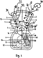
- the Fig. 1 is different from the Fig. 10 in that the housing 1 in the circular-arc-shaped wall 8 has a cooling opening 51 to the chamber 2, In addition, in contrast to the embodiment of Fig. 10 provided in the side wall 6 no inlet and outlet valves. Through the cooling opening 51, a cooling fluid, in the example shown air, flows into the chamber 2 and cools it. In addition, the piston 15 is convectively cooled by the air at least on one of the working surface 30 opposite side 32.
- the piston engine of Fig. 1 is designed as eg compressor and the cooling by means of the cooling opening can increase the efficiency of the compressor.
- a second cooling opening 51 ' may be provided in the side wall 6.
- the second cooling opening is formed, for example, as a cooling fluid outlet, through which the cooling fluid can flow.
- a flow direction of the cooling fluid is indicated in the figure by means of arrows.
- the piston engine of Fig. 2 differs from the embodiment of Fig. 10 in that a cooling opening 52 is provided centrally in the arcuate wall 8. While in the execution of Fig. 1 in one revolution of the crankshaft 19 two working cycles, namely suction and compression, are possible, it is in the embodiment of Fig. 2 four work cycles. Due to the central design of the cooling opening 52, the working chamber 2 can be alternately rinsed left and right with cooling fluid. Depending on the pivotal position of the piston 15, the working chamber 2 opens or closes the working chamber 2.
- the cooling opening 52 in the circular arc-shaped wall 8 is in both the Fig. 1 as well as in the Fig. 2 Defined by a center angle ⁇ , which is smaller than a pivot angle ⁇ of the piston 15.
- the opening 51 and 52 in the arcuate wall 8 extends over an entire axial extent of the arcuate wall 8. That is, the opening 51 and 52 is formed as an elongated groove in the arcuate wall and extending from the front end wall to the rear end wall 7. Alternatively, the cooling opening 51 and 52 may also have a smaller axial extent.
- the Fig. 3 is different from the Fig. 10 in that a cooling opening 53 is arranged in the rear end wall 7. Moreover, in contrast to the execution of the Fig. 10 provided in the side wall 6 no inlet and outlet valves. Furthermore, the piston 15 has only one working surface 30.
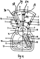
- the embodiment of the Fig. 4 differs from the embodiment of the Fig. 10 in that a cooling opening 54 is arranged centrally in the rear end wall 7. Like in the Fig. 2 Here, too, the opening 54 is arranged centrally. While the piston 15, the opening 53 of the Fig. 3 closes at a pivotal position of the piston 15 on the right side wall 6, the piston 15 closes the opening 54 at a central position of the piston 15 in the Fig. 4 , Both the opening 53 of the Fig. 3 as well as the opening 54 of the Fig. 4 extends over an entire radial extent of the end wall 7 from the bearing housing 3 to the circular arc-shaped wall 8. In both embodiments, the opening 53 and 54 in the front end wall (not shown) is provided. It may also be provided only one opening 53 and 54 in the front end wall or in the rear end wall 7.
- While the piston 15 of the FIGS. 1 and 3 has only one working surface 30, the piston 15 of the FIGS. 2 and 4 in addition to a first work surface 30, a second work surface 29.
- the cooling opening 52 and 54 of the FIGS. 2 and 4 separates a first working chamber from a second working chamber.
- the circular arc-shaped wall 8 of FIG. 2 and the end wall 7 of the FIG. 4 divided in two by the cooling opening 52 and the cooling opening 54.
- the piston engine of Fig. 5 differs from the embodiment of the Fig. 10 in that a cooling opening 55 is provided in the side wall 6. Moreover, in contrast to the execution of the Fig. 10 provided in the side wall 6 no inlet and outlet valves. As a result, the piston 15 has only one working surface 30.
- the cooling opening 55 in the side wall 6 extends over a total radial and axial extent of the side wall 6. That is, in the embodiment of Fig. 5 was dispensed with the entire side wall 6. As a result, a continuous convective cooling of the piston 15 on one of the working surface opposite side 32 is possible.
- the variable working chamber of Fig. 5 completed in each pivotal position of the piston 15.
- Fig. 6a The execution of Fig. 6a is different from the execution of Fig. 10 in that the side wall 6 is omitted altogether and that, moreover, an opening 51 is provided in the circular-arc-shaped wall 8. Moreover, in contrast to the execution of the Fig. 10 No inlet and outlet valves are provided in the side wall 6 and the piston 15 has only one working surface 30.
- the execution of Fig. 6a thus represents a mixed form of FIGS. 5 and 1
- the circular arc-shaped wall 8 of Fig. 6a defines a second center angle ⁇ of about 25 °, which is smaller than the previously described pivoting angle ⁇ of the piston 15.
- the opening 51 in the arcuate wall 8 is defined by the center angle ⁇ . In the Fig. 6a the angles ⁇ and ⁇ are equal. However, they may differ from each other in other embodiments. Thus, the center angle ⁇ may be larger or smaller than the center angle ⁇ .
- the execution of Fig. 6b is thus a hybrid form of the training of FIGS. 2 and 4 .
- the cooling opening 54 of the rear end wall 7 does not extend over an entire radial extent of the end wall 7, but approximately up to one third of the radial extent of the end wall 7.
- the cooling fluid is by means of a blower 60 through the formed as a cooling fluid inlet cooling opening 52 in the circular arc Wall 8 is inserted into the chamber 2.
- the cooling fluid is subsequently discharged from the chamber 2 through the cooling opening 54 formed as a cooling fluid outlet in the rear end wall 7.
- the flow direction of the cooling fluid is indicated by arrows.
- the chamber 2 can thus be flushed particularly well in this embodiment by means of the cooling fluid.
- a cooling opening in the front end wall (not shown) may be provided.
- a cooling opening 54 and 54 ' is provided in the rear end wall 7 and in the front end wall.
- a projection of the cooling opening 54 'of the front end wall on the rear end wall 7 is in the FIG. 6c indicated by dashed lines.
- Cooling fluid is introduced into the chamber 2 by means of an optional blower (not shown) through the cooling opening 54 formed as a cooling fluid inlet in the front end wall. After an effective rinsing and cooling of the chamber 2, the cooling fluid is subsequently discharged from the chamber 2 in the rear end wall 7 by the cooling opening 54 'designed as a cooling fluid outlet.
- the flow direction of the cooling fluid is indicated by an arrow.
- the chamber 2 can thus be flushed particularly well in this embodiment by means of the cooling fluid.
- the flow direction can also be reversed.
- a blower blows the cooling fluid into the chamber 2 through the cooling opening 54 of the rear end wall.
- the cooling fluid leaves the chamber 2 after flushing the chamber 2 through the cooling opening 54 'of the front end wall.
- variable working chamber is closed or opened depending on the pivot position of the piston.
- the piston engine of Fig. 6d differs from the embodiment of the Fig. 10 in that a cooling opening 55 is provided in the side wall 5.
- a second circular arc-shaped wall 70 is fixed, which is arranged on a smaller radius than a maximum radial extent of the piston 15 and engages in the cooling opening 55 of the side wall 5.
- the cooling opening 55 which is likewise designed as a passage for the second circular-arc-shaped wall 70, is provided above the second circular-arc-shaped wall 70 when viewed from the pivot axis 14. It can of course also be arranged below the second circular wall 70.
- a second variable working chamber is defined by the second arcuate wall 70, the piston 15, the side wall 5, the front wall and the rear wall 7 and is sealed off by these walls.
- Fig. 6d There are thus two variable working chambers which are closed in each pivotal position of the piston 15, whereby, for example, a two-stage compression is possible.
- the Figures 1-6d further differ from the FIG. 10 in that a size of the cooling openings 51, 51 ', 52, 53, 54 and 55 is in each case variably controllable or adjustable by means of a slide 61, 61', 62, 63, 64 and 65 arranged in a corresponding housing wall.
- the slide 61, 61 ', 62, 63, 64 and 65 is able to complete the chamber 2 flush and is each connected to an electronic control device, not shown, which is further connected to the piston 15, non-illustrated pressure sensor and temperature sensor is connected.
- the control device is configured to control the spool 61, 61 ', 62, 63, 64 and 65 to regulate the size of the cooling ports 51, 51', 52, 53, 54 and 55 during operation of the reciprocating engine or as needed to enlarge or reduce. From reaching a threshold value of a temperature and / or a pressure in the chamber 2, the cooling opening 51, 51 ', 52, 53, 54 and 55 for cooling the piston 15 and / or the chamber 2 can be opened or closed or its size can be increased or reduced in size. For example, when the temperature measured at the piston 15 is less than or more than a predetermined threshold, the cooling holes 51, 51 ', 52, 53, 54 and 55 may be closed or opened to increase a delivery volume of the reciprocating engine.
- the slide 61, 61 ', 62, 63, 64 and 65 may alternatively be actuated by means of a mechanical control device, for example a camshaft, to more or less close the cooling opening 51, 51', 52, 53, 54, 55 or to open.
- a mechanical control device for example a camshaft
- a throttle or other control device may be provided.
- Cooling fins 31 provided on one of the working surface 30 opposite side 32 of the piston 15 to increase the cooling. Furthermore, to improve the cooling effect in each case in the embodiments of Figures 1-6 an optional blower 60 or a cooling device provided (in the Figures 3 . 4 . 6c . 7 . 8th and 9 not shown), which blows air or another cooling fluid into the cooling opening 51, 52, 53, 54 and 55 as needed.
- the blower 60 is also connected to the said control device.
- the blower 60 is actuated by the control device, in particular, when the slide 61, 62, 63, 64 and 65 opens or closes the respective opening 51, 52, 53, 54 and 55. If no cooling device is provided, the cooling fluid can be sucked by the movement of the piston through the cooling opening 51, 52, 53, 54 and 55.
- a Venturi tube may be provided on the cooling air inlet opening shown in the figures. To increase the cooling effect may be provided on the outside of the housing cooling fins.
- FIGS. 11A, 11B and 12 Referenced.
- FIGS. 11A, 11B and 12 are views of cross sections of a piston engine according to the prior art of DE 10 2010 036 977 B3 shown, which are also included in the present application.
- Pistons 101 and 102 are connected to a rotary cylinder 106 rotatably mounted in the housing 103 about a rotation axis 104 via a bearing 105 and each have a guide groove 107 at one end, into which a crankshaft journal 108 engages a crankshaft 110 connected to a drive shaft 109.
- the guide groove 107 acts as a connecting rod loop or piston loop, which thus forms an integral part the piston 101 and 102 is.
- the two with the respective piston 101 and 102 operatively connected crankshafts 110 are, like the Fig.
- the integrally formed housing 103 comprises - indicated by a dashed line X - two, but rotated by 180 °, joined together housing parts 103a, 103b each having a substantially circular sector-shaped cross-section, in which once on the upper housing wall 111 and once on the lower housing wall 112 the Rotary cylinder 106 of the piston 101 and 102 are mounted.
- a chamber A1 and A2 enclosed by the housing thus has the form of two equal-sized, oppositely lying circular sectors.
- the housing 103 further comprises a housing rear wall 114 and a housing cover 113 and a first side wall 115 and a second side wall 116. The two in each position parallel to each other aligned double piston 101, 102 are in a starting position, as in Fig.
- the piston machine described above can also be operated as a compressor or as an expansion engine or as a combination of these.
- the medium-large working chamber A3 can operate as an expansion engine, while the two outer-small working chambers A1 and A2 operate as a compressor or as a pump and are driven by the expansion motor.
- the inner working chamber A3 and an outer (left) working chamber A1 as the first compressor stage and the other outer working chamber A2 as a second compressor stage could be operated.
- the working chambers A1, A2 and A3 can each fulfill different functions as compressor, pump or motor.
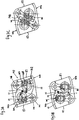
- the embodiment of the Figs. 7A-7C differs from the embodiment of the Fig. 11 in that cooling holes 151 are provided in the side walls 15 and 16, the cooling holes 151 in the side walls 115 and 116 extending over a total radial and axial extent of the side walls 115 and 116.
- the pistons 101 and 102 can be cooled by means of a cooling fluid at least convectively on each side of the piston opposite the working surface of the piston.
- the embodiments of the FIGS. 7a to 7c Incidentally, similar to the embodiment of the Fig. 5 , Instead of two cooling holes 151, as in the FIGS. 7a-c can also be seen in only one of the side walls 115 and 116, a cooling port 151 may be provided. In that case, only one piston 101, 102 is cooled.
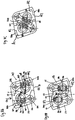
- the embodiment of the Figs. 8A-8C differs from the embodiment of the Fig. 11 in that two cooling openings 152 are provided in the circular arc-shaped wall. Like in the Fig. 11 includes the embodiment of the Fig. 8 also three working chambers A1, A2 and A3. A particularly good cooling effect can be achieved in the working chamber A3, since the cooling holes 152 are arranged opposite one another.
- a cooling fluid for example air, can thus flow in and out, for example, from one side to the other FIG. 8 indicated by arrows 130 and 131.
- the working chambers A1, A2 and A3 and the pistons 101 and 102 can thus be cooled at least convectively by means of a cooling fluid.
- the cooling opening 152 is designed to be just as large as an upper edge 140 of the pistons 101 and 102.
- the cooling opening 152 can also be smaller or larger than the upper edge 140 of the pistons 101 and 102.
- the Fig. 8c are working chambers A1 and A2 open, while in the pivot position of the Fig. 8a the working chamber A3 is largely open.
- the arrangement of the cooling holes 152 in the Fig. 8 Incidentally, the execution of the Fig. 2 , Alternatively, only one cooling opening 152 instead of two cooling openings 152 can be provided here as well.
- FIGS. 7 and 8th are mixed forms of FIGS. 7 and 8th shown, in analogy to the embodiment of the Fig. 6a .
- Fig. 9a is the circular arc in cross-section wall formed by two parts 111 'and 111 "and 112' and 112", which lie radially at different positions.
- the radial gap 140 extends in the pivoting direction over a center angle ⁇ and in the axial direction from the housing cover 113 to the housing rear wall 114.
- the dimensions of the gap 140 can be varied depending on the embodiment in the radial direction, in the axial direction or in the pivoting direction.
- the Fig. 9b is the circular arc-shaped wall 111 "and 112" only as large as the upper edge 140 of the piston 101 and 102.
- the dimensions of the circular arc wall 111 "and 112" may be smaller or larger.
- the piston 101 and 102 can be convectively cooled from several sides. A loss of chamber volume is thus in the FIGS. 9a and 9b compensated by an increased cooling effect.
- the Figures 7-9 further differ from the FIG. 11 in that a size of the cooling openings 151 and 152 is in each case variably controllable or adjustable by means of a slider, not shown, arranged in a corresponding housing wall.
- the slide is able to flush the chamber and is each connected to an electronic control device, not shown, which is further connected to the piston 101 and 102, not shown pressure sensor and temperature sensor.
- the control device is configured to control the slide to regulate or change the size of the cooling opening during operation of the reciprocating engine.
- the cooling apertures 151 and 152 may be more or less opened for cooling the piston 101 and 102 and / or the chamber.
- the slide may alternatively be actuated by means of a mechanical control device, for example a camshaft, to more or less close or open the cooling opening 151 and 152.
- a throttle or other control device may be provided.
- an optional blower or a cooling device provided (in the FIGS. 7 . 8th and 9 each not shown), which blows air or other cooling fluid into the cooling port 151 and 152 as needed.
- the fan is also connected to the mentioned control device.
- the blower is actuated by the control device, in particular, when the slide opens or closes the respective opening 151 and 152. If no cooling device is provided, the cooling fluid can be sucked by the movement of the piston through the cooling holes 151 and 152.
- a Venturi tube may be provided on the cooling air inlet opening shown in the figures. To increase the cooling effect may be provided on the outside of the housing cooling fins.
- FIGS. 7A to 9B can be extended by further side by side, but rotated by 180 ° to each other arranged housing parts with double piston plates.
- the drive or output of the piston engine is not on the illustrated embodiments of FIGS. 1 to 9B limited. It can be provided, for example, that the crank pin of the crankshaft engages in a connecting rod eye of a connecting rod pivotally connected to the piston.
- LIST OF REFERENCE NUMBERS 55 cooling opening 1 housing 60 blowers 2 working chamber 61 slides 3 bearing housing 61 'slide 4 crankcase 62 slides 5 Left sidewall 63 slides 6 right side wall 64 slides 7 front wall 65 slides 8 Circular wall 70 circular wall 9 rotary cylinder 101 piston 10 cups 102 pistons 11 crank radius 103 housing 12 ⁇ fsumpf 103a housing part 13 sealing strips 103b housing part 14 pivot axis 104 axis of rotation 15 pistons 105 bearings 16 connecting rod 106 rotary cylinder 17 guide groove 107 guide groove 18 crankpins 108 crankshaft journals 19 crankshaft 109 drive shaft 22 Left inlet valve 110 crankshaft 23 Left exhaust valve 111 housing wall 24 Right inlet valve 111 'circular arc-shaped wall 25
Landscapes
- Engineering & Computer Science (AREA)
- Mechanical Engineering (AREA)
- General Engineering & Computer Science (AREA)
- Compressor (AREA)
- Pistons, Piston Rings, And Cylinders (AREA)
- Reciprocating Pumps (AREA)
- Details Of Reciprocating Pumps (AREA)
Claims (14)
- Machine à piston, comprenantun carter (103) avec une chambre, qui présente une section transversale sensiblement en forme de secteur circulaire,un piston (101, 102) pivotable conçu sous forme d'élément pivotable et disposé dans le carter (103), doté d'une première surface opérationnelle (29, 30),où le carter (103) et le piston (101, 102) définissent au moins une première chambre de travail (A1, A2, A3) variable,et un rapport d'entrée de couple ou un rapport de sortie de couple en relation avec le piston (101, 102),une soupape de sortie (19a, 19b, 19c) disposée dans la chambre de travail (A1, A2, A3) permettant la sortie d'un fluide de travail, ainsi qu'une soupape d'entrée (18a, 18b, 18c) disposée dans la chambre de travail (A1, A2, A3) permettant l'entrée du fluide de travail dans la chambre de travail (A1, A2, A3),où que le carter (103) présente deux ou plusieurs parties de carter (103a, 103b) respectivement en forme de secteurs circulaires, assemblées l'une à l'autre et pourtant décalées de 180 degrés formant une cavité commune, où respectivement à chaque partie de carter (103a, 103b) est associé un dit piston (101, 102) cité précédemment, où deux parties de carter (103a, 103b) voisines, conjointement avec leurs pistons (101, 102) définissent au moins une chambre de travail (A3) variable, où deux pistons (101, 102) voisins sont disposés l'un par rapport à l'autre décalés de 180 ° dans les parties de carter (103a, 103b) respectives,caractérisée en ce quele carter (103) présente un orifice de refroidissement (152, 160) vers la chambre dans au moins une paroi de carter (111, 112) pour le refroidissement par convexion d'un côté d'un desdits pistons (101, 102) situé en face de la première surface opérationnelle au moyen d'un fluide de refroidissement,où les deux parties de carter voisines présentent respectivement une paroi (111, 112) délimitant la chambre en forme de secteur angulaire dans la section transversale, et un orifice de refroidissement (152, 160) est prévu dans les deux parois en forme de secteurs angulaires, où les orifices de refroidissement (152, 160) sont disposés l'un en face de l'autre de sorte que le fluide de refroidissement peut s'écouler en entrant et en sortant d'un côté jusqu'à l'autre.
- Machine à piston selon la revendication 1, caractérisée en ce que
l'orifice (152) dans la paroi (111, 112) en forme de secteur angulaire est défini par un angle au centre (β), lequel est au plus égal à un angle de pivotement (α) du piston (101, 102). - Machine à piston selon l'une des revendications 1 ou 2, caractérisée en ce que la paroi en forme d'arc de cercle (111, 112) définit un deuxième angle au centre (γ), où un côté de piston (140) orienté vers la paroi en forme d'arc de cercle (111, 112) est en forme d'arc de cercle dans sa section transversale et définit un troisième angle au centre (δ), où le deuxième angle au centre (γ) est exactement égal au troisième angle au centre (δ) ou est inférieur au troisième angle au centre (δ).
- Machine à piston selon l'une des revendications 1 ou 2, caractérisée en ce que la paroi en forme d'arc de cercle (111, 112) définit un deuxième angle au centre (γ), où un côté de piston (140) orienté vers la paroi en forme d'arc de cercle (111, 112) est en forme d'arc de cercle dans la section transversale et définit un troisième angle au centre (δ), où le deuxième angle au centre (γ) est supérieur au troisième angle au centre (δ).
- Machine à piston selon l'une des revendications 1 à 4, caractérisée en ce que l'orifice (152) dans la paroi en forme d'arc de cercle (111, 112) s'étend sur l'extension axiale complète de la paroi en forme d'arc de cercle (111, 112).
- Machine à piston selon l'une des revendications précédentes,
caractérisée en ce qu'un mouvement de pivotement du piston (101, 102) définit un plan de pivotement, et la chambre est délimitée par une paroi avant (113) et une paroi arrière (114), où la paroi avant (113) et la paroi arrière (114) sont parallèles par rapport au plan de pivotement, et en outre un orifice de refroidissement est prévu dans la paroi avant (113) ou dans la paroi arrière (114), ou un orifice de refroidissement est respectivement prévu dans la paroi avant et dans la paroi arrière. - Machine à piston selon la revendication 6, caractérisé en ce que
l'orifice dans la paroi arrière (114) et/ou dans la paroi avant (113) s'étend sur l'extension radiale complète de la paroi arrière (114) et/ou de la paroi avant (113). - Machine à piston selon l'une des revendications 1 à 7, caractérisé en ce que le piston (101, 102) présente sur un côté situé en face de la première surface opérationnelle une deuxième surface opérationnelle, et le piston (15, 101, 102) et le carter (103) définissent une deuxième chambre de travail (A1, A2) variable avec une deuxième soupape de sortie (19a, 19b) γ étant disposée, où un orifice de refroidissement (152) supplémentaire se situe sur une ligne de séparation entre la première chambre de travail (A3) et la deuxième chambre de travail (A1, A2)
- Machine à piston selon l'une des revendications précédentes,
caractérisée en ce que la chambre de travail (A1, A2, A3) est ouverte ou fermée selon la position de pivotement du piston (101, 102). - Machine à piston selon l'une des revendications précédentes,
caractérisée en ce que la chambre est délimitée par une paroi latérale (115, 116) opposée à la première surface opérationnelle, où un orifice de refroidissement (151) supplémentaire est prévu dans la paroi latérale (115, 116). - Machine à piston selon la revendication 10, caractérisé en ce que
l'orifice de refroidissement (51', 55, 151) dans la paroi latérale (6, 115, 116) s'étend sur l'extension radiale complète et/ou l'extension axiale de la paroi latérale (6, 115, 116). - Machine à piston selon l'une des revendications 5, 7 ou 11,
caractérisée en ce que la paroi en forme d'arc de cercle (8, 111, 112), et/ou la paroi avant (113), et/ou la paroi arrière (7, 114), et/ou la paroi latérale (5, 6, 115, 116), est divisée en deux par les orifices de refroidissement (51', 52, 54, 152). - Machine à piston selon l'une des revendications précédentes,
caractérisée en ce qu'une deuxième paroi en forme d'arc de cercle (70) dans la section transversale est fixée sur le piston (15), qui est disposée sur un rayon plus petit que l'extension radiale maximale du piston (15) et se met en prise dans un passage (55) d'une paroi latérale (5) dans une position de pivotement du piston (15), où une deuxième chambre de travail variable est définie par au moins la deuxième paroi (70) en forme d'arc, le piston (15) et la paroi latérale (5). - Machine à piston selon l'une des revendications précédentes,
caractérisée en ce que le piston (101, 102) présente des nervures de refroidissement, et/ouest conçu sous forme de corps creux, et/ouqu'un dispositif de refroidissement, de préférence une soufflerie ou une pompe, est prévu pour le transport du fluide de refroidissement par l'orifice (151, 152, 160) du carter (103) et dans la chambre, et/ouqu'une dimension de l'orifice de refroidissement (151, 152, 160) peut être commandée ou réglée de manière variable, de préférence au moyen d'un organe de réglage, ou d'un poussoir, ou d'une vanne papillon, disposé dans une paroi de carter (111, 112, 114, 115, 116, 117).
Priority Applications (1)
| Application Number | Priority Date | Filing Date | Title |
|---|---|---|---|
| EP19205086.2A EP3660267B1 (fr) | 2014-05-12 | 2015-05-12 | Machine à piston |
Applications Claiming Priority (2)
| Application Number | Priority Date | Filing Date | Title |
|---|---|---|---|
| DE102014208939.5A DE102014208939A1 (de) | 2014-05-12 | 2014-05-12 | Kolbenmaschine |
| PCT/EP2015/060500 WO2015173255A1 (fr) | 2014-05-12 | 2015-05-12 | Machine à piston à refroidissement |
Related Child Applications (1)
| Application Number | Title | Priority Date | Filing Date |
|---|---|---|---|
| EP19205086.2A Division EP3660267B1 (fr) | 2014-05-12 | 2015-05-12 | Machine à piston |
Publications (2)
| Publication Number | Publication Date |
|---|---|
| EP3143258A1 EP3143258A1 (fr) | 2017-03-22 |
| EP3143258B1 true EP3143258B1 (fr) | 2019-10-30 |
Family
ID=53284203
Family Applications (2)
| Application Number | Title | Priority Date | Filing Date |
|---|---|---|---|
| EP15726873.1A Active EP3143258B1 (fr) | 2014-05-12 | 2015-05-12 | Machine à piston à refroidissement |
| EP19205086.2A Active EP3660267B1 (fr) | 2014-05-12 | 2015-05-12 | Machine à piston |
Family Applications After (1)
| Application Number | Title | Priority Date | Filing Date |
|---|---|---|---|
| EP19205086.2A Active EP3660267B1 (fr) | 2014-05-12 | 2015-05-12 | Machine à piston |
Country Status (6)
| Country | Link |
|---|---|
| US (1) | US10221850B2 (fr) |
| EP (2) | EP3143258B1 (fr) |
| CN (1) | CN106536856B (fr) |
| DE (1) | DE102014208939A1 (fr) |
| ES (2) | ES2950131T3 (fr) |
| WO (1) | WO2015173255A1 (fr) |
Cited By (2)
| Publication number | Priority date | Publication date | Assignee | Title |
|---|---|---|---|---|
| DE102022122759A1 (de) | 2022-05-31 | 2023-11-30 | Manfred Max Rapp | Luft-dampf-motor und dessen verwendung |
| WO2023232672A1 (fr) | 2022-05-31 | 2023-12-07 | Manfred Rapp | Moteur à air/vapeur et son utilisation |
Families Citing this family (3)
| Publication number | Priority date | Publication date | Assignee | Title |
|---|---|---|---|---|
| DE102016119985B3 (de) * | 2016-10-20 | 2018-05-17 | Nidec Gpm Gmbh | Pendelkolben-Vakuumpumpe |
| RU2700108C1 (ru) * | 2018-06-01 | 2019-09-12 | Федеральное государственное автономное образовательное учреждение высшего образования "Южно-Уральский государственный университет (национальный исследовательский университет)" ФГАОУ ВО "ЮУрГУ (НИУ)" | Лопастной двигатель |
| DE102018123409A1 (de) | 2018-09-24 | 2020-03-26 | Manfred Max Rapp | Kolbenmaschine, modulares Baukastenystem für eine Kolbenmaschine sowie Verfahren zur Herstellung einer Kolbenmaschine |
Citations (1)
| Publication number | Priority date | Publication date | Assignee | Title |
|---|---|---|---|---|
| DE102010036977B3 (de) * | 2010-08-13 | 2011-11-10 | Manfred Max Rapp | Kolbenmaschine |
Family Cites Families (14)
| Publication number | Priority date | Publication date | Assignee | Title |
|---|---|---|---|---|
| US1363423A (en) * | 1919-11-10 | 1920-12-28 | Pierre Auguste Marie Le | Rotary gas-engine |
| GB331545A (en) * | 1930-03-04 | 1930-07-04 | Paul Polizzi | Improvements in internal combustion engines of the oscillating vane type |
| GB486745A (en) * | 1937-02-23 | 1938-06-09 | Johann Haragsin | Improvements relating to internal combustion engines |
| US3408991A (en) * | 1967-07-12 | 1968-11-05 | William B Pritchett Jr | Oscillating machine |
| DE2353008A1 (de) * | 1973-10-23 | 1975-04-24 | Heinrich Menge | Schwingkolbenmaschine |
| DE3705313A1 (de) * | 1987-02-19 | 1987-10-08 | Franz Josef Knott | Pendelkolbenmaschine |
| US5228414A (en) * | 1992-09-10 | 1993-07-20 | Robert D. Hall | Valveless two-stroke-cycle oscillating engine |
| CN1045119C (zh) * | 1993-09-16 | 1999-09-15 | 枢轴转动工程技术有限公司 | 内燃机 |
| US5979163A (en) * | 1997-12-29 | 1999-11-09 | Circular Motion Controls, Inc. | Rotationally pivotal motion controller |
| AU2182299A (en) * | 1999-01-25 | 2000-08-07 | Klein, Benny | Expansion-compression engine with angularly reciprocating piston |
| DE10254162A1 (de) * | 2002-11-20 | 2004-06-03 | Renner, Bernt | Vorrichtung zum Fördern eines Fluids |
| DE102005010775B3 (de) * | 2005-02-25 | 2006-04-20 | Hüttlin, Herbert, Dr. h.c. | Schwenkkolbenmaschine |
| DE102006024321A1 (de) * | 2006-05-24 | 2007-11-29 | Mehdi Nabhani | Verbrennungsmotor |
| DE102008040574B4 (de) | 2008-07-21 | 2013-08-14 | Manfred Max Rapp | Kolbenmaschine |
-
2014
- 2014-05-12 DE DE102014208939.5A patent/DE102014208939A1/de not_active Withdrawn
-
2015
- 2015-05-12 WO PCT/EP2015/060500 patent/WO2015173255A1/fr not_active Ceased
- 2015-05-12 CN CN201580038189.6A patent/CN106536856B/zh active Active
- 2015-05-12 EP EP15726873.1A patent/EP3143258B1/fr active Active
- 2015-05-12 ES ES19205086T patent/ES2950131T3/es active Active
- 2015-05-12 US US15/309,676 patent/US10221850B2/en active Active
- 2015-05-12 EP EP19205086.2A patent/EP3660267B1/fr active Active
- 2015-05-12 ES ES15726873T patent/ES2766473T3/es active Active
Patent Citations (1)
| Publication number | Priority date | Publication date | Assignee | Title |
|---|---|---|---|---|
| DE102010036977B3 (de) * | 2010-08-13 | 2011-11-10 | Manfred Max Rapp | Kolbenmaschine |
Cited By (3)
| Publication number | Priority date | Publication date | Assignee | Title |
|---|---|---|---|---|
| DE102022122759A1 (de) | 2022-05-31 | 2023-11-30 | Manfred Max Rapp | Luft-dampf-motor und dessen verwendung |
| WO2023232672A1 (fr) | 2022-05-31 | 2023-12-07 | Manfred Rapp | Moteur à air/vapeur et son utilisation |
| DE102022122759B4 (de) * | 2022-05-31 | 2026-02-12 | Max Rapp Motorenbau GmbH & Co. KG | Luft-dampf-motor und dessen verwendung |
Also Published As
| Publication number | Publication date |
|---|---|
| EP3660267B1 (fr) | 2023-04-26 |
| US10221850B2 (en) | 2019-03-05 |
| CN106536856A (zh) | 2017-03-22 |
| WO2015173255A1 (fr) | 2015-11-19 |
| US20170138359A1 (en) | 2017-05-18 |
| EP3660267A1 (fr) | 2020-06-03 |
| ES2766473T3 (es) | 2020-06-12 |
| CN106536856B (zh) | 2019-06-21 |
| DE102014208939A1 (de) | 2015-11-12 |
| ES2950131T3 (es) | 2023-10-05 |
| EP3143258A1 (fr) | 2017-03-22 |
Similar Documents
| Publication | Publication Date | Title |
|---|---|---|
| EP3143258B1 (fr) | Machine à piston à refroidissement | |
| DE102008040574B4 (de) | Kolbenmaschine | |
| EP2603667B1 (fr) | Machine à pistons | |
| DE4333144C2 (de) | Kältemittelkompressor mit hin- und herbeweglichen Kolben | |
| DE923985C (de) | Kolbenkompressor fuer Luft und andere gasfoermige Medien | |
| EP1987233B1 (fr) | Machine à pistons oscillants | |
| DE102005010775B3 (de) | Schwenkkolbenmaschine | |
| DE2332411C3 (de) | Rotationskolbenverdichter | |
| DE4011671A1 (de) | Regelbare fluegelzellenpumpe | |
| DE69800445T2 (de) | Ein- und Auslassventilvorrichtung für einen Kompressor | |
| WO2004088093A1 (fr) | Machine a piston rotatif | |
| DE3401064A1 (de) | Stroemungsmittelpumpe | |
| DE102005024751B4 (de) | Schwenkkolbenmaschine | |
| DE2613472A1 (de) | Trockenlaufender verdichter | |
| WO2017016644A1 (fr) | Système de compression | |
| EP3857026B1 (fr) | Machine à pistons, système modulaire pour une machine à pistons ainsi que procédé pour la fabrication d'une machine à pistons | |
| DE102014214435A1 (de) | Kolbenmaschine | |
| DE102007043674B4 (de) | Spiralverdichter mit Doppelspirale | |
| DE102014115573A1 (de) | Drehventilanordnung für eine Kolben-Zylinder-Einheit | |
| DE102005023721B3 (de) | Schwenkkolbenmaschine | |
| DE102009018870B3 (de) | Hubkolbenverdichter mit Schieberventil | |
| DE19500774A1 (de) | Rotationskolbenmaschine | |
| DE3923059A1 (de) | Rotationskolbenverdichter | |
| DE4318737C2 (de) | Drehkolbenkompressor | |
| DE202010013074U1 (de) | Rotierender Flügelzellen-Kompressor |
Legal Events
| Date | Code | Title | Description |
|---|---|---|---|
| STAA | Information on the status of an ep patent application or granted ep patent |
Free format text: STATUS: THE INTERNATIONAL PUBLICATION HAS BEEN MADE |
|
| PUAI | Public reference made under article 153(3) epc to a published international application that has entered the european phase |
Free format text: ORIGINAL CODE: 0009012 |
|
| STAA | Information on the status of an ep patent application or granted ep patent |
Free format text: STATUS: REQUEST FOR EXAMINATION WAS MADE |
|
| 17P | Request for examination filed |
Effective date: 20161115 |
|
| AK | Designated contracting states |
Kind code of ref document: A1 Designated state(s): AL AT BE BG CH CY CZ DE DK EE ES FI FR GB GR HR HU IE IS IT LI LT LU LV MC MK MT NL NO PL PT RO RS SE SI SK SM TR |
|
| AX | Request for extension of the european patent |
Extension state: BA ME |
|
| DAV | Request for validation of the european patent (deleted) | ||
| DAX | Request for extension of the european patent (deleted) | ||
| STAA | Information on the status of an ep patent application or granted ep patent |
Free format text: STATUS: EXAMINATION IS IN PROGRESS |
|
| 17Q | First examination report despatched |
Effective date: 20180416 |
|
| REG | Reference to a national code |
Ref country code: DE Ref legal event code: R079 Ref document number: 502015010796 Country of ref document: DE Free format text: PREVIOUS MAIN CLASS: F01C0021100000 Ipc: F01C0019000000 |
|
| GRAP | Despatch of communication of intention to grant a patent |
Free format text: ORIGINAL CODE: EPIDOSNIGR1 |
|
| STAA | Information on the status of an ep patent application or granted ep patent |
Free format text: STATUS: GRANT OF PATENT IS INTENDED |
|
| RIC1 | Information provided on ipc code assigned before grant |
Ipc: F01C 21/18 20060101ALI20190429BHEP Ipc: F04C 29/12 20060101ALI20190429BHEP Ipc: F04C 15/06 20060101ALI20190429BHEP Ipc: F01C 21/06 20060101ALI20190429BHEP Ipc: F01C 9/00 20060101ALI20190429BHEP Ipc: F04C 29/04 20060101ALI20190429BHEP Ipc: F01C 19/00 20060101AFI20190429BHEP Ipc: F04C 21/00 20060101ALI20190429BHEP Ipc: F04C 9/00 20060101ALI20190429BHEP Ipc: F01C 21/10 20060101ALI20190429BHEP Ipc: F04C 15/00 20060101ALI20190429BHEP |
|
| INTG | Intention to grant announced |
Effective date: 20190517 |
|
| GRAS | Grant fee paid |
Free format text: ORIGINAL CODE: EPIDOSNIGR3 |
|
| GRAA | (expected) grant |
Free format text: ORIGINAL CODE: 0009210 |
|
| STAA | Information on the status of an ep patent application or granted ep patent |
Free format text: STATUS: THE PATENT HAS BEEN GRANTED |
|
| AK | Designated contracting states |
Kind code of ref document: B1 Designated state(s): AL AT BE BG CH CY CZ DE DK EE ES FI FR GB GR HR HU IE IS IT LI LT LU LV MC MK MT NL NO PL PT RO RS SE SI SK SM TR |
|
| REG | Reference to a national code |
Ref country code: GB Ref legal event code: FG4D Free format text: NOT ENGLISH |
|
| REG | Reference to a national code |
Ref country code: CH Ref legal event code: EP |
|
| REG | Reference to a national code |
Ref country code: AT Ref legal event code: REF Ref document number: 1196338 Country of ref document: AT Kind code of ref document: T Effective date: 20191115 |
|
| REG | Reference to a national code |
Ref country code: DE Ref legal event code: R096 Ref document number: 502015010796 Country of ref document: DE |
|
| REG | Reference to a national code |
Ref country code: IE Ref legal event code: FG4D Free format text: LANGUAGE OF EP DOCUMENT: GERMAN |
|
| REG | Reference to a national code |
Ref country code: LT Ref legal event code: MG4D |
|
| PG25 | Lapsed in a contracting state [announced via postgrant information from national office to epo] |
Ref country code: SE Free format text: LAPSE BECAUSE OF FAILURE TO SUBMIT A TRANSLATION OF THE DESCRIPTION OR TO PAY THE FEE WITHIN THE PRESCRIBED TIME-LIMIT Effective date: 20191030 Ref country code: NL Free format text: LAPSE BECAUSE OF FAILURE TO SUBMIT A TRANSLATION OF THE DESCRIPTION OR TO PAY THE FEE WITHIN THE PRESCRIBED TIME-LIMIT Effective date: 20191030 Ref country code: PL Free format text: LAPSE BECAUSE OF FAILURE TO SUBMIT A TRANSLATION OF THE DESCRIPTION OR TO PAY THE FEE WITHIN THE PRESCRIBED TIME-LIMIT Effective date: 20191030 Ref country code: LT Free format text: LAPSE BECAUSE OF FAILURE TO SUBMIT A TRANSLATION OF THE DESCRIPTION OR TO PAY THE FEE WITHIN THE PRESCRIBED TIME-LIMIT Effective date: 20191030 Ref country code: NO Free format text: LAPSE BECAUSE OF FAILURE TO SUBMIT A TRANSLATION OF THE DESCRIPTION OR TO PAY THE FEE WITHIN THE PRESCRIBED TIME-LIMIT Effective date: 20200130 Ref country code: GR Free format text: LAPSE BECAUSE OF FAILURE TO SUBMIT A TRANSLATION OF THE DESCRIPTION OR TO PAY THE FEE WITHIN THE PRESCRIBED TIME-LIMIT Effective date: 20200131 Ref country code: BG Free format text: LAPSE BECAUSE OF FAILURE TO SUBMIT A TRANSLATION OF THE DESCRIPTION OR TO PAY THE FEE WITHIN THE PRESCRIBED TIME-LIMIT Effective date: 20200130 Ref country code: LV Free format text: LAPSE BECAUSE OF FAILURE TO SUBMIT A TRANSLATION OF THE DESCRIPTION OR TO PAY THE FEE WITHIN THE PRESCRIBED TIME-LIMIT Effective date: 20191030 Ref country code: FI Free format text: LAPSE BECAUSE OF FAILURE TO SUBMIT A TRANSLATION OF THE DESCRIPTION OR TO PAY THE FEE WITHIN THE PRESCRIBED TIME-LIMIT Effective date: 20191030 Ref country code: PT Free format text: LAPSE BECAUSE OF FAILURE TO SUBMIT A TRANSLATION OF THE DESCRIPTION OR TO PAY THE FEE WITHIN THE PRESCRIBED TIME-LIMIT Effective date: 20200302 |
|
| REG | Reference to a national code |
Ref country code: NL Ref legal event code: MP Effective date: 20191030 |
|
| PG25 | Lapsed in a contracting state [announced via postgrant information from national office to epo] |
Ref country code: RS Free format text: LAPSE BECAUSE OF FAILURE TO SUBMIT A TRANSLATION OF THE DESCRIPTION OR TO PAY THE FEE WITHIN THE PRESCRIBED TIME-LIMIT Effective date: 20191030 Ref country code: HR Free format text: LAPSE BECAUSE OF FAILURE TO SUBMIT A TRANSLATION OF THE DESCRIPTION OR TO PAY THE FEE WITHIN THE PRESCRIBED TIME-LIMIT Effective date: 20191030 Ref country code: IS Free format text: LAPSE BECAUSE OF FAILURE TO SUBMIT A TRANSLATION OF THE DESCRIPTION OR TO PAY THE FEE WITHIN THE PRESCRIBED TIME-LIMIT Effective date: 20200229 |
|
| REG | Reference to a national code |
Ref country code: ES Ref legal event code: FG2A Ref document number: 2766473 Country of ref document: ES Kind code of ref document: T3 Effective date: 20200612 |
|
| PG25 | Lapsed in a contracting state [announced via postgrant information from national office to epo] |
Ref country code: AL Free format text: LAPSE BECAUSE OF FAILURE TO SUBMIT A TRANSLATION OF THE DESCRIPTION OR TO PAY THE FEE WITHIN THE PRESCRIBED TIME-LIMIT Effective date: 20191030 |
|
| PG25 | Lapsed in a contracting state [announced via postgrant information from national office to epo] |
Ref country code: RO Free format text: LAPSE BECAUSE OF FAILURE TO SUBMIT A TRANSLATION OF THE DESCRIPTION OR TO PAY THE FEE WITHIN THE PRESCRIBED TIME-LIMIT Effective date: 20191030 Ref country code: CZ Free format text: LAPSE BECAUSE OF FAILURE TO SUBMIT A TRANSLATION OF THE DESCRIPTION OR TO PAY THE FEE WITHIN THE PRESCRIBED TIME-LIMIT Effective date: 20191030 Ref country code: EE Free format text: LAPSE BECAUSE OF FAILURE TO SUBMIT A TRANSLATION OF THE DESCRIPTION OR TO PAY THE FEE WITHIN THE PRESCRIBED TIME-LIMIT Effective date: 20191030 Ref country code: DK Free format text: LAPSE BECAUSE OF FAILURE TO SUBMIT A TRANSLATION OF THE DESCRIPTION OR TO PAY THE FEE WITHIN THE PRESCRIBED TIME-LIMIT Effective date: 20191030 |
|
| REG | Reference to a national code |
Ref country code: DE Ref legal event code: R097 Ref document number: 502015010796 Country of ref document: DE |
|
| PG25 | Lapsed in a contracting state [announced via postgrant information from national office to epo] |
Ref country code: SK Free format text: LAPSE BECAUSE OF FAILURE TO SUBMIT A TRANSLATION OF THE DESCRIPTION OR TO PAY THE FEE WITHIN THE PRESCRIBED TIME-LIMIT Effective date: 20191030 Ref country code: SM Free format text: LAPSE BECAUSE OF FAILURE TO SUBMIT A TRANSLATION OF THE DESCRIPTION OR TO PAY THE FEE WITHIN THE PRESCRIBED TIME-LIMIT Effective date: 20191030 |
|
| PLBE | No opposition filed within time limit |
Free format text: ORIGINAL CODE: 0009261 |
|
| STAA | Information on the status of an ep patent application or granted ep patent |
Free format text: STATUS: NO OPPOSITION FILED WITHIN TIME LIMIT |
|
| 26N | No opposition filed |
Effective date: 20200731 |
|
| PG25 | Lapsed in a contracting state [announced via postgrant information from national office to epo] |
Ref country code: SI Free format text: LAPSE BECAUSE OF FAILURE TO SUBMIT A TRANSLATION OF THE DESCRIPTION OR TO PAY THE FEE WITHIN THE PRESCRIBED TIME-LIMIT Effective date: 20191030 |
|
| PG25 | Lapsed in a contracting state [announced via postgrant information from national office to epo] |
Ref country code: CH Free format text: LAPSE BECAUSE OF NON-PAYMENT OF DUE FEES Effective date: 20200531 Ref country code: MC Free format text: LAPSE BECAUSE OF FAILURE TO SUBMIT A TRANSLATION OF THE DESCRIPTION OR TO PAY THE FEE WITHIN THE PRESCRIBED TIME-LIMIT Effective date: 20191030 Ref country code: LI Free format text: LAPSE BECAUSE OF NON-PAYMENT OF DUE FEES Effective date: 20200531 |
|
| REG | Reference to a national code |
Ref country code: BE Ref legal event code: MM Effective date: 20200531 |
|
| PG25 | Lapsed in a contracting state [announced via postgrant information from national office to epo] |
Ref country code: LU Free format text: LAPSE BECAUSE OF NON-PAYMENT OF DUE FEES Effective date: 20200512 |
|
| PG25 | Lapsed in a contracting state [announced via postgrant information from national office to epo] |
Ref country code: IE Free format text: LAPSE BECAUSE OF NON-PAYMENT OF DUE FEES Effective date: 20200512 |
|
| PG25 | Lapsed in a contracting state [announced via postgrant information from national office to epo] |
Ref country code: BE Free format text: LAPSE BECAUSE OF NON-PAYMENT OF DUE FEES Effective date: 20200531 |
|
| REG | Reference to a national code |
Ref country code: AT Ref legal event code: MM01 Ref document number: 1196338 Country of ref document: AT Kind code of ref document: T Effective date: 20200512 |
|
| PG25 | Lapsed in a contracting state [announced via postgrant information from national office to epo] |
Ref country code: AT Free format text: LAPSE BECAUSE OF NON-PAYMENT OF DUE FEES Effective date: 20200512 |
|
| PG25 | Lapsed in a contracting state [announced via postgrant information from national office to epo] |
Ref country code: TR Free format text: LAPSE BECAUSE OF FAILURE TO SUBMIT A TRANSLATION OF THE DESCRIPTION OR TO PAY THE FEE WITHIN THE PRESCRIBED TIME-LIMIT Effective date: 20191030 Ref country code: MT Free format text: LAPSE BECAUSE OF FAILURE TO SUBMIT A TRANSLATION OF THE DESCRIPTION OR TO PAY THE FEE WITHIN THE PRESCRIBED TIME-LIMIT Effective date: 20191030 Ref country code: CY Free format text: LAPSE BECAUSE OF FAILURE TO SUBMIT A TRANSLATION OF THE DESCRIPTION OR TO PAY THE FEE WITHIN THE PRESCRIBED TIME-LIMIT Effective date: 20191030 |
|
| PG25 | Lapsed in a contracting state [announced via postgrant information from national office to epo] |
Ref country code: MK Free format text: LAPSE BECAUSE OF FAILURE TO SUBMIT A TRANSLATION OF THE DESCRIPTION OR TO PAY THE FEE WITHIN THE PRESCRIBED TIME-LIMIT Effective date: 20191030 |
|
| PGFP | Annual fee paid to national office [announced via postgrant information from national office to epo] |
Ref country code: DE Payment date: 20250530 Year of fee payment: 11 |
|
| PGFP | Annual fee paid to national office [announced via postgrant information from national office to epo] |
Ref country code: GB Payment date: 20250521 Year of fee payment: 11 Ref country code: ES Payment date: 20250627 Year of fee payment: 11 |
|
| PGFP | Annual fee paid to national office [announced via postgrant information from national office to epo] |
Ref country code: IT Payment date: 20250527 Year of fee payment: 11 |
|
| PGFP | Annual fee paid to national office [announced via postgrant information from national office to epo] |
Ref country code: FR Payment date: 20250528 Year of fee payment: 11 |