EP3143463B1 - Schnellkorrekturmechanismus für uhr - Google Patents
Schnellkorrekturmechanismus für uhr Download PDFInfo
- Publication number
- EP3143463B1 EP3143463B1 EP15714517.8A EP15714517A EP3143463B1 EP 3143463 B1 EP3143463 B1 EP 3143463B1 EP 15714517 A EP15714517 A EP 15714517A EP 3143463 B1 EP3143463 B1 EP 3143463B1
- Authority
- EP
- European Patent Office
- Prior art keywords
- wheel set
- display
- intermediate wheel
- stage
- date
- Prior art date
- Legal status (The legal status is an assumption and is not a legal conclusion. Google has not performed a legal analysis and makes no representation as to the accuracy of the status listed.)
- Active
Links
Images


Classifications
-
- G—PHYSICS
- G04—HOROLOGY
- G04B—MECHANICALLY-DRIVEN CLOCKS OR WATCHES; MECHANICAL PARTS OF CLOCKS OR WATCHES IN GENERAL; TIME PIECES USING THE POSITION OF THE SUN, MOON OR STARS
- G04B19/00—Indicating the time by visual means
- G04B19/24—Clocks or watches with date or week-day indicators, i.e. calendar clocks or watches; Clockwork calendars
- G04B19/243—Clocks or watches with date or week-day indicators, i.e. calendar clocks or watches; Clockwork calendars characterised by the shape of the date indicator
- G04B19/247—Clocks or watches with date or week-day indicators, i.e. calendar clocks or watches; Clockwork calendars characterised by the shape of the date indicator disc-shaped
- G04B19/25—Devices for setting the date indicators manually
-
- G—PHYSICS
- G04—HOROLOGY
- G04B—MECHANICALLY-DRIVEN CLOCKS OR WATCHES; MECHANICAL PARTS OF CLOCKS OR WATCHES IN GENERAL; TIME PIECES USING THE POSITION OF THE SUN, MOON OR STARS
- G04B13/00—Gearwork
-
- G—PHYSICS
- G04—HOROLOGY
- G04B—MECHANICALLY-DRIVEN CLOCKS OR WATCHES; MECHANICAL PARTS OF CLOCKS OR WATCHES IN GENERAL; TIME PIECES USING THE POSITION OF THE SUN, MOON OR STARS
- G04B15/00—Escapements
- G04B15/14—Component parts or constructional details, e.g. construction of the lever or the escape wheel
-
- G—PHYSICS
- G04—HOROLOGY
- G04B—MECHANICALLY-DRIVEN CLOCKS OR WATCHES; MECHANICAL PARTS OF CLOCKS OR WATCHES IN GENERAL; TIME PIECES USING THE POSITION OF THE SUN, MOON OR STARS
- G04B18/00—Mechanisms for setting frequency
- G04B18/02—Regulator or adjustment devices; Indexing devices, e.g. raquettes
-
- G—PHYSICS
- G04—HOROLOGY
- G04B—MECHANICALLY-DRIVEN CLOCKS OR WATCHES; MECHANICAL PARTS OF CLOCKS OR WATCHES IN GENERAL; TIME PIECES USING THE POSITION OF THE SUN, MOON OR STARS
- G04B19/00—Indicating the time by visual means
- G04B19/24—Clocks or watches with date or week-day indicators, i.e. calendar clocks or watches; Clockwork calendars
- G04B19/243—Clocks or watches with date or week-day indicators, i.e. calendar clocks or watches; Clockwork calendars characterised by the shape of the date indicator
- G04B19/247—Clocks or watches with date or week-day indicators, i.e. calendar clocks or watches; Clockwork calendars characterised by the shape of the date indicator disc-shaped
- G04B19/253—Driving or releasing mechanisms
- G04B19/25333—Driving or releasing mechanisms wherein the date indicators are driven or released mechanically by a clockwork movement
- G04B19/25373—Driving or releasing mechanisms wherein the date indicators are driven or released mechanically by a clockwork movement driven or released stepwise by an energy source which is released at determined moments by the clockwork movement
- G04B19/2538—Driving or releasing mechanisms wherein the date indicators are driven or released mechanically by a clockwork movement driven or released stepwise by an energy source which is released at determined moments by the clockwork movement automatically corrected at the end of months having less than 31 days
-
- G—PHYSICS
- G04—HOROLOGY
- G04B—MECHANICALLY-DRIVEN CLOCKS OR WATCHES; MECHANICAL PARTS OF CLOCKS OR WATCHES IN GENERAL; TIME PIECES USING THE POSITION OF THE SUN, MOON OR STARS
- G04B27/00—Mechanical devices for setting the time indicating means
-
- G—PHYSICS
- G04—HOROLOGY
- G04B—MECHANICALLY-DRIVEN CLOCKS OR WATCHES; MECHANICAL PARTS OF CLOCKS OR WATCHES IN GENERAL; TIME PIECES USING THE POSITION OF THE SUN, MOON OR STARS
- G04B27/00—Mechanical devices for setting the time indicating means
- G04B27/02—Mechanical devices for setting the time indicating means by making use of the winding means
- G04B27/06—Mechanical devices for setting the time indicating means by making use of the winding means with rocking bar
-
- G—PHYSICS
- G04—HOROLOGY
- G04C—ELECTROMECHANICAL CLOCKS OR WATCHES
- G04C11/00—Synchronisation of independently-driven clocks
- G04C11/06—Synchronisation of independently-driven clocks with direct mechanical action on the time-indicating means
Definitions
- the invention relates to a display mechanism for a timepiece, comprising a mechanism for rapidly correcting the position of a display mobile.
- the invention also relates to a watch movement comprising at least one such display mechanism.
- the invention also relates to a timepiece or watch comprising at least one such movement and / or at least one such display mechanism.
- the invention relates to the field of clock display mechanisms, and more particularly including fast correction mechanisms.
- This invention relates to watches which require a fast correction mechanism (day, month, or other) of certain functions, in particular display functions such as a calendar (annual, perpetual, day / date, or other), or moon phase, tide, AM / PM, or other indicators.
- a fast correction mechanism day, month, or other
- display functions such as a calendar (annual, perpetual, day / date, or other), or moon phase, tide, AM / PM, or other indicators.
- WO 2012/175595 A1 discloses a date display mechanism for a timepiece, comprising a fast correction mechanism of the position of a display mobile, including a return wheel.
- a date display mechanism for a timepiece comprising a fast correction mechanism of the position of a display mobile, including a return wheel.
- the user To make a correction of the month, the user must generally make a correction by the date. In the most unfavorable cases, such manipulation can be long and tedious. It may be necessary to make a one-year correction. Similarly if the user is mistaken during the correction, the manipulation must be repeated. The execution of the correction mechanism by the date could lead to excessive use and possibly create malfunctions.
- the correction mechanisms often include flip-flops, which are essential components in clockwork mechanisms, making it possible to switch a mechanism between several different modes, generally between two distinct positions.
- a clock rocker is often accompanied by a return spring to ensure a proper movement transmission, or a support maintained, as appropriate.
- the invention proposes to prevent such a desynchronization of a date mechanism, and allows the date mechanism to synchronize itself.
- the present invention proposes to solve the aforementioned drawbacks of the prior art, and aims to prevent any desynchronization of the mechanism.
- the invention relates to a clock display mechanism according to claim 1.
- the invention further relates to a watch movement comprising at least one such display mechanism.
- the invention also relates to a timepiece or watch comprising at least one such movement and / or at least one such display mechanism.
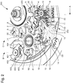
- the invention relates to the field of watch mechanisms, and more particularly mechanisms for controlling and transmitting motion. It finds a preferential application for the correction and updating of display mechanisms, and more particularly for display mechanisms 500 comprising a user-controlled rapid correction mechanism 200, via control means. 17 such as a rod or the like.
- Such a display mechanism 500 is conventionally driven by an automatic drive mechanism controlled by a movement 1000 that includes the timepiece 2000, in particular a watch, in which this display mechanism is integrated 500.
- the kinematic chain of the In normal operation, the display mechanism ensures, by a drive means 1, the periodic drive of at least one display mobile 3.
- this periodic drive is performed directly by a mobile 1C downstream of a gear driven by the movement 1000, preferably arranged to make a turn in twenty-four hours.
- the clock display mechanisms generally comprise at least one mounted mobile idler, which is held in position by friction, or by elastic return means, such as a jumper or the like.
- a rapid correction mechanism 200 generally comprises means arranged to disengage the automatic drive mechanism, and to replace, at least one mobile of the drive train of this automatic drive mechanism, at least one other mobile arranged to drive directly or indirectly at least one display mobile 3, and thus perform a modification of its position.
- the invention proposes to improve such a mechanism to make it impossible to desynchronize the assembly.
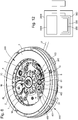
- the fast correction mechanism 200 comprises, in the immediate vicinity of the display unit 3, at least one deflection wheel 6, which pivots in normal operation in a single direction S.
- the diverting wheel 6 can fill, on different parallel floors, different functions.
- the return mobile ensures, on a first stage 61, the synchronization with the display mechanism 500: the angular orientation of the deflection wheel 6 relative to the automatic drive mechanism of the display mechanism is then correct .
- the display mechanism 500 comprises, interposed between the mobile 6 and the display mobile 3, a security latch 400 also called synchronization flip-flop.
- the first mobile unit for the first stage 61 and the second mobile unit for the second stage 62 are integral in rotation.
- the diverting wheel 6 is in one piece.
- the security latch 400 is advantageously equipped with elastic return means 403, which tend to recall it permanently in a rest position, which is the position of the beginning of cooperation, to the following period, with the display mobile 3.
- the deflection wheel 6 comprises a first return wheel to the first stage 61, and a second return wheel to the second stage 62.
- the first deflection wheel has teeth that are alternated with other teeth that includes the second deflection wheel.
- the teeth of the first deflection wheel and those of the second deflection wheel have the same profile, and some of them are aligned.
- the first deflection wheel comprises half less teeth than the second return wheel, identical and aligned at one of two.
- the common teeth extend on a double thickness at the first stage 61 and at the second stage 62, while the teeth of the second deflection wheel which have no corresponding at the level of the first idler wheel do not extend only on the second stage 62.
- the second deflection wheel comprises ten teeth
- the first deflection wheel comprises five.
- the security latch 400 has a blade portion 404, which extends only to the first stage.
- This blade 404 comprises an abutment surface 402 arranged to push the teeth of the first deflection mobile to the first stage 61 in case of desynchronization.
- flip-flop 400 On the opposite side with respect to a pivot axis B, flip-flop 400 preferably has a spout 401 arranged to cooperate with display unit 3, for driving safety latch 400 by the latter.
- the deflection wheel 6 further comprises, on a third stage which does not interfere with the safety latch 400, a third gear 63.
- This third gear 63 is then arranged to mesh, directly or indirectly. , with another mobile display.
- the display mechanism 500 is a date mechanism 300, comprising a date driving mobile 1 arranged to be controlled by a wheel of a movement. timepiece 1000 and arranged to control an annual wheel 4.
- At least one said mobile display 3 is a date ring, and this date mechanism 300 comprises control means arranged to drive directly or indirectly this at least A calendar ring 3.
- the date mechanism 300 further comprises such a date rapid correction mechanism 200, which is arranged to directly or indirectly control the pivoting of this date ring 3.
- this date mechanism 300 further comprises, at a fourth level below the third lower level 32, a correction finger 14, which comprises the rapid date correction mechanism 200, and which is arranged to cooperate with the teeth 34 located at lower level 32 of the date ring 3, for the correction of the date.
- the date ring 3 can be indifferently made in a single piece or with elements juxtaposed and indexed between them.
- a particular application of the invention relates to an annual calendar mechanism 300 as described by the patent EP1666991B1 the same depositor.
- the mobile display 3 is described here, without limitation, under the form of a date ring, arranged to carry at least one date indicator ring, not shown in the figures.
- This date ring can be, in known manner, maintained by a jumper so as to achieve a semi-instantaneous passage.
- This annual calendar mechanism 300 which can be embodied in the form of a module attached to an existing movement mechanism, is arranged to be driven by a wheel 1C, for example a wheel of hours, of a movement 1000, no shown in detail in the figures, and which may be a mechanical movement as well as an electronic movement.
- This cam 2 has, radially projecting, five secondary pins 2E which correspond to months of less than thirty-one days: February, April, June, September, November, and which are angularly distributed according to the time interval between these respective months: 60 °, 60 °, 90 °, 60 °, 90 °.
- the cam 2 is disengaged between these secondary pins 2E, so that the second monthly finger 12 drives the cam 2 only during the last days of these particular months, the month of February requiring manual additional correction, depending on the year In progress.
- the cam 2 is integral with an annual wheel 4.
- this annual wheel 4 comprises twenty-four teeth. It may be is intended to carry, in certain embodiments, a disc or a month indicator ring, not shown in the figures.
- the annual wheel 4 can support a star of the month 5, which pivots in free rotation.
- This star of the months 5 may be is intended to carry, in certain variants execution, a disk or a month indicator ring, not shown in the figures.
- the return wheel 6 is arranged to connect, at the end of each month, the annual wheel 4 with a main pin 35 located at a second intermediate level 31 of the date ring 3.
- the return wheel 6 comprises a second return wheel 62. At the end of each month, whatever its duration, this second return wheel 62 drives the main pin 35.
- the return wheel 6 cooperates, by a third gear wheel 63 to a third lower level 32, with the annual wheel 4.
- the deflection wheel 6 comprises, in the alignment of the first upper level 30, a first return wheel to the first stage 61, integral with the second return wheel of the second stage 62.
- the first deflection wheel of the first stage 61 cooperates with the star of the months 5 mounted crazy and maintained friction.
- the first idler gear 61 and the third gear 63 each have ten equidistant teeth.
- the second monthly finger 1B of the indicator wheel drive indicator 1 drives the cam 2, and the annual wheel 4 thus causes, on the one hand, the return wheel 6 and the date ring 1 by its main pin 35, and secondly the star of the months 5.
- the date ring 3 has a particular arrangement, since it comprises twenty-nine fingers 33, situated at an upper level 30 parallel to the lower level 32, where the thirty-one teeth 34 are arranged. These fingers 33 are arranged to cooperate with each other. with an external spout 401 of the security latch 400, opposite the bearing face 402 that includes this latch 400 to push the toothing of the first return wheel 61 in case of desynchronization.
- the single main pin of the date ring 3 extends at least over the height of the second return wheel of the second stage 62.
- the system can not desynchronize because the main pin 35 is still in engagement with the diverting wheel 6.
- one of the twenty-nine fingers 33 drives the security latch 400, to ensure, if necessary, the synchronization of the system as explained above. .
- the figure 7 shows the relative arrangement of the levels of the date ring.
- the toothing of twenty-nine fingers 33, at the upper level 30, corresponds to a set of thirty-one equidistant teeth from which two consecutive teeth would have been removed.
- the main pin 35 is, here, positioned between the second and third fingers 33 which follow the toothless space located at the upper level 30.
- the toothing located at the first upper level 30 is therefore only used to activate the synchronization, its teeth are active and drive the latch 400. While the usual drive of the date ring 3 is made by the toothing 4 with the teeth. 3, at the bottom third level 32.
- the date mechanism 300 comprises at least one fast correction mechanism 200, which comprises one or more correcting fingers 12 or 14, arranged to modify the angular position of a return wheel 6, and / or to act directly on the position of a display such as a disk or a ring carrying a date ring, month, day, year, leap year, or other.
- a fast correction mechanism 200 which comprises one or more correcting fingers 12 or 14, arranged to modify the angular position of a return wheel 6, and / or to act directly on the position of a display such as a disk or a ring carrying a date ring, month, day, year, leap year, or other.
- the fast correction mechanism 200 comprises a flip-flop 100, pivoting about a first fixed axis D1, and which bears on a second axis D2 which is parallel to the first axis D1 an output mobile which comprises at least two stages and carries at least, on two different planes, a corrector finger 14 and a corrector 12, which are arranged to modify the position of a date mobile or a date correction mobile, and a month viewer or a mobile display month display. More particularly, the correction finger 14 cooperates with the date ring 3 for the correction of the date, and the corrector 12 cooperates with the second return wheel of the second stage 62 for correction of the month.
- the invention also relates to a watch movement 1000 comprising an hour wheel driving at least one such calendar mechanism 300.
- the invention also relates to a timepiece 2000, in particular a watch, comprising at least one such movement 1000 and / or at least one such display mechanism and / or such a date mechanism 300.
- the invention provides a new security in the use of a display mechanism having a fast correction function. Indeed, the user does not have the means to check if the system is synchronized or not.
- the invention enables the display mechanism, particularly a date mechanism, to synchronize itself.
Landscapes
- Physics & Mathematics (AREA)
- General Physics & Mathematics (AREA)
- Electromechanical Clocks (AREA)
Claims (9)
- Anzeigemechanismus (500) für ein Zeitmessgerät (2000), umfassend einen Schnellkorrekturmechanismus (200) für die Position eines Anzeigedrehteils (3), wobei der Anzeigemechanismus (500) mindestens ein bewegliches Zeigerstellrad (6) aufweist, das dafür ausgelegt ist, mit selbsttätigen Antriebsmitteln kinematisch verbunden zu sein, dadurch gekennzeichnet, dass zwischen das bewegliche Zeigerstellrad (6) und das Anzeigedrehteil (3) eine Sicherungswippe (400) eingefügt ist und dass die Sicherungswippe (400) dafür ausgelegt ist, angetrieben zu werden durch das Anzeigedrehteil (3) während seines periodischen Antriebs entlang einer Bahn, die in den Raumbereich des beweglichen Zeigerstellrades (6) eingreift, derart, dass:- dann, wenn das bewegliche Zeigerstellrad (6) mit den selbsttätigen Antriebsmitteln richtig synchronisiert ist, die Bahn der Wippe (400) nicht in das bewegliche Zeigerstellrad (6) eingreift;- dann, wenn das bewegliche Zeigerstellrad (6) mit den selbsttätigen Antriebsmitteln nicht richtig synchronisiert ist, dessen Bahn bei der Schnellkorrektur in das bewegliche Zeigerstellrad (6) eingreift, welches die Sicherungswippe (400) dann in der Richtung antreibt, die zu der Einbahnrichtung ihres Normalbetriebs gegenläufig ist, um das bewegliche Zeigerstellrad (6) neu zu synchronisieren.
- Anzeigemechanismus (500) nach Anspruch 1, der dafür ausgelegt ist, durch einen selbsttätigen Antriebsmechanismus angetrieben zu werden, der durch ein Uhrwerk (1000) gesteuert wird, wobei die kinematische Kette des Anzeigemechanismus (500) dafür ausgelegt ist, den periodischen Antrieb mindestens eines ersten Anzeigedrehteils (3) sicherzustellen, wobei der Anzeigemechanismus (500) einen Schnellkorrekturmechanismus (200) mit Mitteln, die dafür ausgelegt sind, den automatischen Antriebsmechanismus auszurücken, umfasst, und mindestens ein Drehteil der kinematischen Kette des selbsttätigen Antriebsmechanismus durch mindestens ein weiteres Drehteil zu ersetzen, das dafür ausgelegt ist, mindestens das erste Anzeigedrehteil (3) direkt oder indirekt anzutreiben und eine Veränderung der Position des ersten Anzeigedrehteils (3) zu bewirken, dadurch gekennzeichnet, dass der Schnellkorrekturmechanismus (200) mindestens ein bewegliches Zeigerstellrad (6) umfasst, das dafür ausgelegt ist, auf einer ersten Stufe (61) die Synchronisation mit den selbsttätigen Antriebsmitteln des Anzeigemechanismus (500) sicherzustellen, und dass der Anzeigemechanismus (500) eingefügt zwischen das bewegliche Zeigerstellrad (6) und das Anzeigedrehteil (3) eine Sicherungswippe (400) aufweist, die dafür ausgelegt ist, durch das Anzeigedrehteil (3) während des periodischen Antriebs des Anzeigedrehteils (3) entlang einer bestimmten Bahn und auf einem Weg, der in den Raumbereich des beweglichen Zeigerstellrades (6) eingreift, angetrieben zu werden, wobei die relative Anordnung der Sicherungswippe (400) und des beweglichen Zeigerstellrades (6), die drehbar um parallele und voneinander verschiedene Achsen montiert sind, derart ist, dass:- dann, wenn das bewegliche Zeigerstellrad (6) richtig synchronisiert ist, die Bahn der Sicherungswippe (400) nicht in die erste Stufe (61) des beweglichen Zeigerstellrades (6) eingreift und die Sicherungswippe (400) dafür ausgelegt ist, sich entfernt von jeder anderen Oberfläche des beweglichen Zeigerstellrades (6) zu bewegen, ohne in das bewegliche Zeigerstellrad (6) einzugreifen,- dann, wenn das bewegliche Zeigerstellrad (6) nicht richtig synchronisiert ist, die Bahn der Sicherungswippe (400) in die erste Stufe (61) des beweglichen Zeigerstellrades (6) eingreift und die Sicherungswippe (400) dafür ausgelegt ist, das bewegliche Zeigerstellrad (6) in einer Richtung anzutreiben, die zu der Einbahnrichtung seines Normalbetriebs gegenläufig ist, um das bewegliche Zeigerstellrad (6) neu zu synchronisieren.
- Anzeigemechanismus (500) nach Anspruch 2, dadurch gekennzeichnet, dass das bewegliche Zeigerstellrad (6) dafür ausgelegt ist, die Synchronisation auf der ersten Stufe (61) sicherzustellen und auf einer zweiten Stufe (62) den direkten oder indirekten Antrieb eines von dem ersten Anzeigedrehteil (3) verschiedenen anderen Anzeigedrehteils sicherzustellen, und ferner dadurch gekennzeichnet, dass die relative Anordnung der Sicherungswippe (400) und des beweglichen Zeigerstellrades (6) derart ist, dass:- dann, wenn das bewegliche Zeigerstellrad (6) richtig synchronisiert ist, die Bahn der Sicherungswippe (400) nicht in die erste Stufe (61) des beweglichen Zeigerstellrades (6) eingreift und die Sicherungswippe (400) dafür ausgelegt ist, sich oberhalb der zweiten Stufe (62) des beweglichen Zeigerstellrades (6) und in einem Abstand hiervon zu bewegen, ohne in dieses einzugreifen;- dann, wenn das bewegliche Zeigerstellrad (6) nicht richtig synchronisiert ist, die Bahn der Sicherungswippe (400) in die erste Stufe (61) des beweglichen Zeigerstellrades (6) eingreift und die Sicherungswippe (400) dafür ausgelegt ist, das bewegliche Zeigerstellrad (6) in einer Richtung anzutreiben, die zu der Einbahnrichtung seines Normalbetriebs gegenläufig ist, um das bewegliche Zeigerstellrad (6) neu zu synchronisieren.
- Anzeigemechanismus (500) nach Anspruch 2 oder 3, dadurch gekennzeichnet, dass die Sicherungswippe (400) elastische Rückstellmittel (403) umfasst, die bestrebt sind, sie ständig in eine Ruheposition zurückzustellen, die die Anfangsposition der Zusammenwirkung in der folgenden Periode mit dem Anzeigedrehteil (3) ist.
- Anzeigemechanismus (500) nach einem der Ansprüche 2 bis 4, dadurch gekennzeichnet, dass er ein Datumsmechanismus (300) ist, der ein Datumsantriebsdrehteil (1) umfasst, das dafür ausgelegt ist, durch ein Rad eines Uhrwerks (1000) gesteuert zu werden, und dafür ausgelegt ist, ein Jahresrad (4) zu steuern, dass mindestens ein Anzeigedrehteil (3) ein Datumsring ist und dass der Datumsmechanismus (300) Steuermittel umfasst, die dafür ausgelegt sind, den mindestens einen Datumsring (3) direkt oder indirekt anzutreiben, wobei der Datumsmechanismus (300) ferner einen Datums-Schnellkorrekturmechanismus (200) umfasst, der dafür ausgelegt ist, die Drehung des Datumsrings (3) direkt oder indirekt zu steuern, dadurch gekennzeichnet, dass der Schnellkorrekturmechanismus (200) ein bewegliches Zeigerstellrad (6) aufweist, das aneinander befestigt und angeordnet auf parallelen Ebenen umfasst:- auf einer ersten, oberen Ebene (30) ein erstes Vorgelegerad der ersten Stufe (61), das dafür ausgelegt ist, entweder mit der Sicherungswippe (400), die ferner dafür ausgelegt ist, auf derselben Ebene mit Fingern (33) zusammenzuwirken, die der Datumsring (3) aufweist, oder mit einem Monatsstern (5), der an dem Jahresrad (4) frei drehbar montiert ist, zusammenzuwirken;- auf einer zweiten, mittleren Ebene (31) ein zweites Vorgelegerad der zweiten Stufe (62), das dafür ausgelegt ist, an jedem Monatsende mit einem Vorsprung (35) zusammenzuwirken, den der Datumsring (3) aufweist, der dafür ausgelegt ist, auf einer unteren Ebene (32) durch das Datumsantriebsdrehteil (1) angetrieben zu werden;- auf der dritten, unteren Ebene (32) ein drittes Vorgelegerad (63), das mit dem ersten Vorgelegerad der ersten Stufe (61) und mit dem zweiten Vorgelegerad der zweiten Stufe (62) fest verbunden und hierzu koaxial ist und dafür ausgelegt ist, mit dem Jahresrad (4) zusammenzuwirken, wobei auf der dritten, unteren Ebene (32) ein Korrekturvorgelege (12), das der Datums-Schnellkorrekturmechanismus (200) aufweist, dafür ausgelegt ist, mit dem zweiten Vorgelegerad der zweiten Stufe (62) zusammenzuwirken, um den Monat zu korrigieren.
- Anzeigemechanismus (500) nach Anspruch 5, dadurch gekennzeichnet, dass der Datumsmechanismus (300) außerdem auf einer vierten Ebene unterhalb der dritten, unteren Ebene (32) einen Korrekturfinger (14) aufweist, den der Datums-Schnellkorrekturmechanismus (200) umfasst, der dafür ausgelegt ist, mit den Zähnen (34) zusammenzuwirken, die der Datumsring (3) auf der unteren Ebene (32) aufweist, um das Datum zu korrigieren.
- Anzeigemechanismus (500) nach Anspruch 5 oder 6, dadurch gekennzeichnet, dass der Datumsring (3) auf der oberen Ebene (30) eine Zahnung mit neunundzwanzig Fingern (33) für den Antrieb der Wippe (400) parallel zu einer Zahnung mit einunddreißig Zähnen (34) auf der unteren Ebene (32) für den Antrieb und die Aktualisierung des Datumsrings (3) durch ein Werk (1000) oder durch einen Benutzer und zwischen der oberen Ebene (30) und der unteren Ebene (32) auf der zweiten, mittleren Ebene (31) einen einzigen Hauptvorsprung (35) für die Steuerung der Änderung der Monatsanzeige umfasst.
- Uhrwerk (1000), umfassend ein Stundenrad, das mindestens einen Datumsmechanismus (300) nach einem der Ansprüche 5 bis 7 umfasst.
- Zeitmessgerät (2000) oder Uhr, umfassend mindestens ein Werk (1000) nach Anspruch 8 und/oder mindestens einen Datumsmechanismus (300) nach einem der Ansprüche 5 bis 7.
Applications Claiming Priority (2)
| Application Number | Priority Date | Filing Date | Title |
|---|---|---|---|
| EP14168333.4A EP2945026B1 (de) | 2014-05-14 | 2014-05-14 | Schnellkorrekturmechanismus für Uhr |
| PCT/EP2015/057673 WO2015172943A2 (fr) | 2014-05-14 | 2015-04-09 | Mecanisme d'affichage d'horlogerie comportant une correction rapide |
Publications (2)
| Publication Number | Publication Date |
|---|---|
| EP3143463A2 EP3143463A2 (de) | 2017-03-22 |
| EP3143463B1 true EP3143463B1 (de) | 2018-10-10 |
Family
ID=66629845
Family Applications (1)
| Application Number | Title | Priority Date | Filing Date |
|---|---|---|---|
| EP15714517.8A Active EP3143463B1 (de) | 2014-05-14 | 2015-04-09 | Schnellkorrekturmechanismus für uhr |
Country Status (6)
| Country | Link |
|---|---|
| US (1) | US9841734B2 (de) |
| EP (1) | EP3143463B1 (de) |
| JP (1) | JP6182679B2 (de) |
| CN (1) | CN106104394B (de) |
| CH (1) | CH709632B1 (de) |
| WO (1) | WO2015172943A2 (de) |
Families Citing this family (9)
| Publication number | Priority date | Publication date | Assignee | Title |
|---|---|---|---|---|
| EP3396472B1 (de) * | 2017-04-28 | 2020-05-27 | ETA SA Manufacture Horlogère Suisse | Datums- und mondphasenanzeigemechanismus für armbanduhr |
| EP3499317B1 (de) * | 2017-12-13 | 2024-08-21 | Rolex Sa | Triebfeder eines kalender-uhrwerksmechanismus |
| EP3547043B1 (de) | 2018-03-26 | 2021-02-17 | Montres Breguet S.A. | Korrekturmechanismus der uhranzeige |
| EP3923084B1 (de) | 2020-06-12 | 2024-07-24 | ETA SA Manufacture Horlogère Suisse | Antikorrektursystem einer anzeige für eine uhr |
| EP3955065B1 (de) * | 2020-08-14 | 2024-09-04 | Rolex Sa | Indexierungsvorrichtung einer zugstange |
| US12314010B2 (en) | 2021-03-04 | 2025-05-27 | Rolex Sa | Device for selecting timepiece functions |
| US12326695B2 (en) * | 2021-03-04 | 2025-06-10 | Rolex Sa | Device for selecting timepiece functions |
| EP4053639B1 (de) | 2021-03-04 | 2025-01-01 | Rolex Sa | Vorrichtung zur auswahl von uhrfunktionen |
| EP4276545B1 (de) * | 2022-05-13 | 2024-12-18 | Blancpain SA | Anterograder anzeigemechanismus für uhr |
Family Cites Families (8)
| Publication number | Priority date | Publication date | Assignee | Title |
|---|---|---|---|---|
| US3427798A (en) * | 1966-11-10 | 1969-02-18 | Hamilton Watch Co | Watch calendar setting mechanism |
| US3890778A (en) * | 1973-08-02 | 1975-06-24 | Ebauches Sa | Watch stem intermediate setting position with functions determined by whether intermediate position was achieved by pushing stem in or pulling stem out |
| US4027468A (en) * | 1975-10-31 | 1977-06-07 | General Time Corporation | Day-date mechanism for travel clock |
| JP4296018B2 (ja) * | 2003-03-27 | 2009-07-15 | セイコーインスツル株式会社 | カレンダ機構を備えたクロノグラフ時計 |
| DE08405164T1 (de) * | 2007-07-02 | 2009-09-24 | Rolex Sa | Uhr, die mit einer Vorrichtung zur Steuerung von Funktionen und/oder Stundenanzeigen ausgerüstet ist |
| EP2490084B1 (de) * | 2011-02-17 | 2016-07-20 | Glashütter Uhrenbetrieb GmbH | Datumsmechanismus |
| WO2012175595A1 (fr) * | 2011-06-21 | 2012-12-27 | Rolex S.A. | Piece d'horlogerie comportant un mecanisme de remontage et au moins un mecanisme de correction d'au moins un organe indicateur |
| EP2642354B1 (de) * | 2012-03-23 | 2015-10-21 | Omega SA | Anzeige- und Korrekturmechanismus des Zustands von mindestens zwei verschiedenen zeitlichen Größen |
-
2015
- 2015-04-09 CN CN201580013900.2A patent/CN106104394B/zh active Active
- 2015-04-09 JP JP2016555714A patent/JP6182679B2/ja active Active
- 2015-04-09 US US15/125,231 patent/US9841734B2/en active Active
- 2015-04-09 WO PCT/EP2015/057673 patent/WO2015172943A2/fr not_active Ceased
- 2015-04-09 EP EP15714517.8A patent/EP3143463B1/de active Active
- 2015-04-09 CH CH00492/15A patent/CH709632B1/fr unknown
Also Published As
| Publication number | Publication date |
|---|---|
| WO2015172943A2 (fr) | 2015-11-19 |
| CN106104394A (zh) | 2016-11-09 |
| CH709632B1 (fr) | 2019-06-28 |
| JP6182679B2 (ja) | 2017-08-16 |
| WO2015172943A4 (fr) | 2016-02-25 |
| CH709632A2 (fr) | 2015-11-30 |
| US9841734B2 (en) | 2017-12-12 |
| WO2015172943A3 (fr) | 2016-01-07 |
| CN106104394B (zh) | 2018-06-01 |
| EP3143463A2 (de) | 2017-03-22 |
| JP2017516977A (ja) | 2017-06-22 |
| US20170075307A1 (en) | 2017-03-16 |
Similar Documents
| Publication | Publication Date | Title |
|---|---|---|
| EP3143463B1 (de) | Schnellkorrekturmechanismus für uhr | |
| EP2453322B1 (de) | Schneller Korrektor einer Zeitgrößenanzeige für Uhr | |
| EP2624075B1 (de) | Uhr | |
| EP3021175B1 (de) | Rattrapantenmechanismus mit planetengetriebe für uhren | |
| EP2490083A1 (de) | Programmrädchen eines Datumsmechanismus | |
| EP3009893B1 (de) | Ewiger Kalender mit Ausgleichsgetriebe | |
| EP2008159B1 (de) | Uhr mit einem zwei-zeitzonen-mechanismus | |
| EP2490082A1 (de) | Kalendersmechanismus | |
| EP3382468B1 (de) | Uhrwerk mit verlängerung der gangreserve | |
| EP3032358B1 (de) | Chronografen-Mechanismus für Uhr | |
| EP2811347B1 (de) | Uhrmechanismus zur Speicherung und Anzeige einer Zeitanzeige | |
| EP3040786B1 (de) | Echter ewiger Kalender | |
| EP3904964B1 (de) | Anzeigevorrichtung einer uhrzeitanzeige oder eines abgeleiteten uhrzeitwerts und indexierungsvorrichtung | |
| EP3173876A1 (de) | Kalendersystem für uhr | |
| EP3333641B1 (de) | Uhrwerksmechanismus zur steuerung einer vielzahl von anzeigen | |
| EP3173877A1 (de) | Kalendersystem für uhr | |
| EP3173878A1 (de) | Kalendersystem für uhr | |
| EP3333642B1 (de) | Uhrwerksmechanismus zum bidirektionalen korrigieren einer vielzahl von anzeigen | |
| EP3701336B1 (de) | Korrekturvorrichtung für eine uhr | |
| EP2933692B1 (de) | Anzeigevorrichtung | |
| EP3026506A1 (de) | Zeitmessgerät mit Geschwindigkeitswahlschalter | |
| EP3904962B1 (de) | Indexierungsvorrichtung und anzeigevorrichtung einer uhrzeitanzeige oder eines abgeleiteten uhrzeitwerts | |
| CH681128B5 (de) | ||
| CH715723B1 (fr) | Mécanisme de saut instantané d'un mobile d'affichage. | |
| CH713658B1 (fr) | Mouvement horloger comprenant deux organes réglants. |
Legal Events
| Date | Code | Title | Description |
|---|---|---|---|
| STAA | Information on the status of an ep patent application or granted ep patent |
Free format text: STATUS: THE INTERNATIONAL PUBLICATION HAS BEEN MADE |
|
| PUAI | Public reference made under article 153(3) epc to a published international application that has entered the european phase |
Free format text: ORIGINAL CODE: 0009012 |
|
| STAA | Information on the status of an ep patent application or granted ep patent |
Free format text: STATUS: REQUEST FOR EXAMINATION WAS MADE |
|
| 17P | Request for examination filed |
Effective date: 20161214 |
|
| AK | Designated contracting states |
Kind code of ref document: A2 Designated state(s): AL AT BE BG CH CY CZ DE DK EE ES FI FR GB GR HR HU IE IS IT LI LT LU LV MC MK MT NL NO PL PT RO RS SE SI SK SM TR |
|
| AX | Request for extension of the european patent |
Extension state: BA ME |
|
| DAV | Request for validation of the european patent (deleted) | ||
| DAX | Request for extension of the european patent (deleted) | ||
| GRAP | Despatch of communication of intention to grant a patent |
Free format text: ORIGINAL CODE: EPIDOSNIGR1 |
|
| STAA | Information on the status of an ep patent application or granted ep patent |
Free format text: STATUS: GRANT OF PATENT IS INTENDED |
|
| INTG | Intention to grant announced |
Effective date: 20180601 |
|
| GRAS | Grant fee paid |
Free format text: ORIGINAL CODE: EPIDOSNIGR3 |
|
| GRAA | (expected) grant |
Free format text: ORIGINAL CODE: 0009210 |
|
| STAA | Information on the status of an ep patent application or granted ep patent |
Free format text: STATUS: THE PATENT HAS BEEN GRANTED |
|
| AK | Designated contracting states |
Kind code of ref document: B1 Designated state(s): AL AT BE BG CH CY CZ DE DK EE ES FI FR GB GR HR HU IE IS IT LI LT LU LV MC MK MT NL NO PL PT RO RS SE SI SK SM TR |
|
| REG | Reference to a national code |
Ref country code: GB Ref legal event code: FG4D Free format text: NOT ENGLISH |
|
| REG | Reference to a national code |
Ref country code: CH Ref legal event code: EP Ref country code: AT Ref legal event code: REF Ref document number: 1051962 Country of ref document: AT Kind code of ref document: T Effective date: 20181015 |
|
| REG | Reference to a national code |
Ref country code: IE Ref legal event code: FG4D Free format text: LANGUAGE OF EP DOCUMENT: FRENCH |
|
| REG | Reference to a national code |
Ref country code: DE Ref legal event code: R096 Ref document number: 602015017834 Country of ref document: DE |
|
| REG | Reference to a national code |
Ref country code: CH Ref legal event code: NV Representative=s name: ICB INGENIEURS CONSEILS EN BREVETS SA, CH |
|
| REG | Reference to a national code |
Ref country code: NL Ref legal event code: MP Effective date: 20181010 |
|
| REG | Reference to a national code |
Ref country code: LT Ref legal event code: MG4D |
|
| REG | Reference to a national code |
Ref country code: AT Ref legal event code: MK05 Ref document number: 1051962 Country of ref document: AT Kind code of ref document: T Effective date: 20181010 |
|
| PG25 | Lapsed in a contracting state [announced via postgrant information from national office to epo] |
Ref country code: NL Free format text: LAPSE BECAUSE OF FAILURE TO SUBMIT A TRANSLATION OF THE DESCRIPTION OR TO PAY THE FEE WITHIN THE PRESCRIBED TIME-LIMIT Effective date: 20181010 |
|
| PG25 | Lapsed in a contracting state [announced via postgrant information from national office to epo] |
Ref country code: ES Free format text: LAPSE BECAUSE OF FAILURE TO SUBMIT A TRANSLATION OF THE DESCRIPTION OR TO PAY THE FEE WITHIN THE PRESCRIBED TIME-LIMIT Effective date: 20181010 Ref country code: NO Free format text: LAPSE BECAUSE OF FAILURE TO SUBMIT A TRANSLATION OF THE DESCRIPTION OR TO PAY THE FEE WITHIN THE PRESCRIBED TIME-LIMIT Effective date: 20190110 Ref country code: IS Free format text: LAPSE BECAUSE OF FAILURE TO SUBMIT A TRANSLATION OF THE DESCRIPTION OR TO PAY THE FEE WITHIN THE PRESCRIBED TIME-LIMIT Effective date: 20190210 Ref country code: HR Free format text: LAPSE BECAUSE OF FAILURE TO SUBMIT A TRANSLATION OF THE DESCRIPTION OR TO PAY THE FEE WITHIN THE PRESCRIBED TIME-LIMIT Effective date: 20181010 Ref country code: AT Free format text: LAPSE BECAUSE OF FAILURE TO SUBMIT A TRANSLATION OF THE DESCRIPTION OR TO PAY THE FEE WITHIN THE PRESCRIBED TIME-LIMIT Effective date: 20181010 Ref country code: LT Free format text: LAPSE BECAUSE OF FAILURE TO SUBMIT A TRANSLATION OF THE DESCRIPTION OR TO PAY THE FEE WITHIN THE PRESCRIBED TIME-LIMIT Effective date: 20181010 Ref country code: BG Free format text: LAPSE BECAUSE OF FAILURE TO SUBMIT A TRANSLATION OF THE DESCRIPTION OR TO PAY THE FEE WITHIN THE PRESCRIBED TIME-LIMIT Effective date: 20190110 Ref country code: PL Free format text: LAPSE BECAUSE OF FAILURE TO SUBMIT A TRANSLATION OF THE DESCRIPTION OR TO PAY THE FEE WITHIN THE PRESCRIBED TIME-LIMIT Effective date: 20181010 Ref country code: FI Free format text: LAPSE BECAUSE OF FAILURE TO SUBMIT A TRANSLATION OF THE DESCRIPTION OR TO PAY THE FEE WITHIN THE PRESCRIBED TIME-LIMIT Effective date: 20181010 Ref country code: LV Free format text: LAPSE BECAUSE OF FAILURE TO SUBMIT A TRANSLATION OF THE DESCRIPTION OR TO PAY THE FEE WITHIN THE PRESCRIBED TIME-LIMIT Effective date: 20181010 |
|
| PG25 | Lapsed in a contracting state [announced via postgrant information from national office to epo] |
Ref country code: RS Free format text: LAPSE BECAUSE OF FAILURE TO SUBMIT A TRANSLATION OF THE DESCRIPTION OR TO PAY THE FEE WITHIN THE PRESCRIBED TIME-LIMIT Effective date: 20181010 Ref country code: SE Free format text: LAPSE BECAUSE OF FAILURE TO SUBMIT A TRANSLATION OF THE DESCRIPTION OR TO PAY THE FEE WITHIN THE PRESCRIBED TIME-LIMIT Effective date: 20181010 Ref country code: AL Free format text: LAPSE BECAUSE OF FAILURE TO SUBMIT A TRANSLATION OF THE DESCRIPTION OR TO PAY THE FEE WITHIN THE PRESCRIBED TIME-LIMIT Effective date: 20181010 Ref country code: GR Free format text: LAPSE BECAUSE OF FAILURE TO SUBMIT A TRANSLATION OF THE DESCRIPTION OR TO PAY THE FEE WITHIN THE PRESCRIBED TIME-LIMIT Effective date: 20190111 Ref country code: PT Free format text: LAPSE BECAUSE OF FAILURE TO SUBMIT A TRANSLATION OF THE DESCRIPTION OR TO PAY THE FEE WITHIN THE PRESCRIBED TIME-LIMIT Effective date: 20190210 |
|
| REG | Reference to a national code |
Ref country code: DE Ref legal event code: R097 Ref document number: 602015017834 Country of ref document: DE |
|
| PG25 | Lapsed in a contracting state [announced via postgrant information from national office to epo] |
Ref country code: CZ Free format text: LAPSE BECAUSE OF FAILURE TO SUBMIT A TRANSLATION OF THE DESCRIPTION OR TO PAY THE FEE WITHIN THE PRESCRIBED TIME-LIMIT Effective date: 20181010 Ref country code: IT Free format text: LAPSE BECAUSE OF FAILURE TO SUBMIT A TRANSLATION OF THE DESCRIPTION OR TO PAY THE FEE WITHIN THE PRESCRIBED TIME-LIMIT Effective date: 20181010 Ref country code: DK Free format text: LAPSE BECAUSE OF FAILURE TO SUBMIT A TRANSLATION OF THE DESCRIPTION OR TO PAY THE FEE WITHIN THE PRESCRIBED TIME-LIMIT Effective date: 20181010 |
|
| PLBE | No opposition filed within time limit |
Free format text: ORIGINAL CODE: 0009261 |
|
| STAA | Information on the status of an ep patent application or granted ep patent |
Free format text: STATUS: NO OPPOSITION FILED WITHIN TIME LIMIT |
|
| PG25 | Lapsed in a contracting state [announced via postgrant information from national office to epo] |
Ref country code: EE Free format text: LAPSE BECAUSE OF FAILURE TO SUBMIT A TRANSLATION OF THE DESCRIPTION OR TO PAY THE FEE WITHIN THE PRESCRIBED TIME-LIMIT Effective date: 20181010 Ref country code: SM Free format text: LAPSE BECAUSE OF FAILURE TO SUBMIT A TRANSLATION OF THE DESCRIPTION OR TO PAY THE FEE WITHIN THE PRESCRIBED TIME-LIMIT Effective date: 20181010 Ref country code: RO Free format text: LAPSE BECAUSE OF FAILURE TO SUBMIT A TRANSLATION OF THE DESCRIPTION OR TO PAY THE FEE WITHIN THE PRESCRIBED TIME-LIMIT Effective date: 20181010 Ref country code: SK Free format text: LAPSE BECAUSE OF FAILURE TO SUBMIT A TRANSLATION OF THE DESCRIPTION OR TO PAY THE FEE WITHIN THE PRESCRIBED TIME-LIMIT Effective date: 20181010 |
|
| 26N | No opposition filed |
Effective date: 20190711 |
|
| PG25 | Lapsed in a contracting state [announced via postgrant information from national office to epo] |
Ref country code: SI Free format text: LAPSE BECAUSE OF FAILURE TO SUBMIT A TRANSLATION OF THE DESCRIPTION OR TO PAY THE FEE WITHIN THE PRESCRIBED TIME-LIMIT Effective date: 20181010 |
|
| REG | Reference to a national code |
Ref country code: BE Ref legal event code: MM Effective date: 20190430 |
|
| GBPC | Gb: european patent ceased through non-payment of renewal fee |
Effective date: 20190409 |
|
| PG25 | Lapsed in a contracting state [announced via postgrant information from national office to epo] |
Ref country code: LU Free format text: LAPSE BECAUSE OF NON-PAYMENT OF DUE FEES Effective date: 20190409 Ref country code: MC Free format text: LAPSE BECAUSE OF FAILURE TO SUBMIT A TRANSLATION OF THE DESCRIPTION OR TO PAY THE FEE WITHIN THE PRESCRIBED TIME-LIMIT Effective date: 20181010 |
|
| PG25 | Lapsed in a contracting state [announced via postgrant information from national office to epo] |
Ref country code: GB Free format text: LAPSE BECAUSE OF NON-PAYMENT OF DUE FEES Effective date: 20190409 |
|
| PG25 | Lapsed in a contracting state [announced via postgrant information from national office to epo] |
Ref country code: BE Free format text: LAPSE BECAUSE OF NON-PAYMENT OF DUE FEES Effective date: 20190430 |
|
| PG25 | Lapsed in a contracting state [announced via postgrant information from national office to epo] |
Ref country code: TR Free format text: LAPSE BECAUSE OF FAILURE TO SUBMIT A TRANSLATION OF THE DESCRIPTION OR TO PAY THE FEE WITHIN THE PRESCRIBED TIME-LIMIT Effective date: 20181010 |
|
| PG25 | Lapsed in a contracting state [announced via postgrant information from national office to epo] |
Ref country code: IE Free format text: LAPSE BECAUSE OF NON-PAYMENT OF DUE FEES Effective date: 20190409 |
|
| PG25 | Lapsed in a contracting state [announced via postgrant information from national office to epo] |
Ref country code: CY Free format text: LAPSE BECAUSE OF FAILURE TO SUBMIT A TRANSLATION OF THE DESCRIPTION OR TO PAY THE FEE WITHIN THE PRESCRIBED TIME-LIMIT Effective date: 20181010 |
|
| PG25 | Lapsed in a contracting state [announced via postgrant information from national office to epo] |
Ref country code: MT Free format text: LAPSE BECAUSE OF FAILURE TO SUBMIT A TRANSLATION OF THE DESCRIPTION OR TO PAY THE FEE WITHIN THE PRESCRIBED TIME-LIMIT Effective date: 20181010 Ref country code: HU Free format text: LAPSE BECAUSE OF FAILURE TO SUBMIT A TRANSLATION OF THE DESCRIPTION OR TO PAY THE FEE WITHIN THE PRESCRIBED TIME-LIMIT; INVALID AB INITIO Effective date: 20150409 |
|
| PG25 | Lapsed in a contracting state [announced via postgrant information from national office to epo] |
Ref country code: MK Free format text: LAPSE BECAUSE OF FAILURE TO SUBMIT A TRANSLATION OF THE DESCRIPTION OR TO PAY THE FEE WITHIN THE PRESCRIBED TIME-LIMIT Effective date: 20181010 |
|
| P01 | Opt-out of the competence of the unified patent court (upc) registered |
Effective date: 20230701 |
|
| PGFP | Annual fee paid to national office [announced via postgrant information from national office to epo] |
Ref country code: DE Payment date: 20250319 Year of fee payment: 11 |
|
| PGFP | Annual fee paid to national office [announced via postgrant information from national office to epo] |
Ref country code: CH Payment date: 20250501 Year of fee payment: 11 |
|
| PGFP | Annual fee paid to national office [announced via postgrant information from national office to epo] |
Ref country code: FR Payment date: 20260320 Year of fee payment: 12 |