EP4053639B1 - Vorrichtung zur auswahl von uhrfunktionen - Google Patents
Vorrichtung zur auswahl von uhrfunktionen Download PDFInfo
- Publication number
- EP4053639B1 EP4053639B1 EP21160830.2A EP21160830A EP4053639B1 EP 4053639 B1 EP4053639 B1 EP 4053639B1 EP 21160830 A EP21160830 A EP 21160830A EP 4053639 B1 EP4053639 B1 EP 4053639B1
- Authority
- EP
- European Patent Office
- Prior art keywords
- lever
- configuration
- interface element
- selection device
- pull
- Prior art date
- Legal status (The legal status is an assumption and is not a legal conclusion. Google has not performed a legal analysis and makes no representation as to the accuracy of the status listed.)
- Active
Links
Images





Classifications
-
- G—PHYSICS
- G04—HOROLOGY
- G04B—MECHANICALLY-DRIVEN CLOCKS OR WATCHES; MECHANICAL PARTS OF CLOCKS OR WATCHES IN GENERAL; TIME PIECES USING THE POSITION OF THE SUN, MOON OR STARS
- G04B27/00—Mechanical devices for setting the time indicating means
- G04B27/02—Mechanical devices for setting the time indicating means by making use of the winding means
- G04B27/04—Mechanical devices for setting the time indicating means by making use of the winding means with clutch wheel
- G04B27/045—Changing the winding position to the setting position and vice versa is done with an independant part of the winding or setting mechanism
-
- G—PHYSICS
- G04—HOROLOGY
- G04B—MECHANICALLY-DRIVEN CLOCKS OR WATCHES; MECHANICAL PARTS OF CLOCKS OR WATCHES IN GENERAL; TIME PIECES USING THE POSITION OF THE SUN, MOON OR STARS
- G04B19/00—Indicating the time by visual means
- G04B19/02—Back-gearing arrangements between gear train and hands
-
- G—PHYSICS
- G04—HOROLOGY
- G04B—MECHANICALLY-DRIVEN CLOCKS OR WATCHES; MECHANICAL PARTS OF CLOCKS OR WATCHES IN GENERAL; TIME PIECES USING THE POSITION OF THE SUN, MOON OR STARS
- G04B13/00—Gearwork
- G04B13/02—Wheels; Pinions; Spindles; Pivots
- G04B13/021—Wheels; Pinions; Spindles; Pivots elastic fitting with a spindle, axis or shaft
- G04B13/023—Wheels; Pinions; Spindles; Pivots elastic fitting with a spindle, axis or shaft allowing rotational slipping when a threshold torque is exceeded
-
- G—PHYSICS
- G04—HOROLOGY
- G04B—MECHANICALLY-DRIVEN CLOCKS OR WATCHES; MECHANICAL PARTS OF CLOCKS OR WATCHES IN GENERAL; TIME PIECES USING THE POSITION OF THE SUN, MOON OR STARS
- G04B19/00—Indicating the time by visual means
- G04B19/24—Clocks or watches with date or week-day indicators, i.e. calendar clocks or watches; Clockwork calendars
-
- G—PHYSICS
- G04—HOROLOGY
- G04B—MECHANICALLY-DRIVEN CLOCKS OR WATCHES; MECHANICAL PARTS OF CLOCKS OR WATCHES IN GENERAL; TIME PIECES USING THE POSITION OF THE SUN, MOON OR STARS
- G04B19/00—Indicating the time by visual means
- G04B19/24—Clocks or watches with date or week-day indicators, i.e. calendar clocks or watches; Clockwork calendars
- G04B19/243—Clocks or watches with date or week-day indicators, i.e. calendar clocks or watches; Clockwork calendars characterised by the shape of the date indicator
- G04B19/247—Clocks or watches with date or week-day indicators, i.e. calendar clocks or watches; Clockwork calendars characterised by the shape of the date indicator disc-shaped
- G04B19/25—Devices for setting the date indicators manually
-
- G—PHYSICS
- G04—HOROLOGY
- G04B—MECHANICALLY-DRIVEN CLOCKS OR WATCHES; MECHANICAL PARTS OF CLOCKS OR WATCHES IN GENERAL; TIME PIECES USING THE POSITION OF THE SUN, MOON OR STARS
- G04B27/00—Mechanical devices for setting the time indicating means
- G04B27/004—Mechanical devices for setting the time indicating means having several simultaneous functions, e.g. stopping or starting the clockwork or the hands
-
- G—PHYSICS
- G04—HOROLOGY
- G04B—MECHANICALLY-DRIVEN CLOCKS OR WATCHES; MECHANICAL PARTS OF CLOCKS OR WATCHES IN GENERAL; TIME PIECES USING THE POSITION OF THE SUN, MOON OR STARS
- G04B27/00—Mechanical devices for setting the time indicating means
- G04B27/02—Mechanical devices for setting the time indicating means by making use of the winding means
- G04B27/026—Mechanical devices for setting the time indicating means by making use of the winding means for several clockworks or pairs of hands and/or supplementary functions
-
- G—PHYSICS
- G04—HOROLOGY
- G04B—MECHANICALLY-DRIVEN CLOCKS OR WATCHES; MECHANICAL PARTS OF CLOCKS OR WATCHES IN GENERAL; TIME PIECES USING THE POSITION OF THE SUN, MOON OR STARS
- G04B27/00—Mechanical devices for setting the time indicating means
- G04B27/02—Mechanical devices for setting the time indicating means by making use of the winding means
- G04B27/04—Mechanical devices for setting the time indicating means by making use of the winding means with clutch wheel
-
- G—PHYSICS
- G04—HOROLOGY
- G04B—MECHANICALLY-DRIVEN CLOCKS OR WATCHES; MECHANICAL PARTS OF CLOCKS OR WATCHES IN GENERAL; TIME PIECES USING THE POSITION OF THE SUN, MOON OR STARS
- G04B27/00—Mechanical devices for setting the time indicating means
- G04B27/02—Mechanical devices for setting the time indicating means by making use of the winding means
- G04B27/06—Mechanical devices for setting the time indicating means by making use of the winding means with rocking bar
-
- G—PHYSICS
- G04—HOROLOGY
- G04B—MECHANICALLY-DRIVEN CLOCKS OR WATCHES; MECHANICAL PARTS OF CLOCKS OR WATCHES IN GENERAL; TIME PIECES USING THE POSITION OF THE SUN, MOON OR STARS
- G04B3/00—Normal winding of clockworks by hand or mechanically; Winding up several mainsprings or driving weights simultaneously
- G04B3/04—Rigidly-mounted keys, knobs or crowns
- G04B3/046—Operation by rotation and axial movement with extra function of axial shift of operating element, e.g. crown combined with push button
Definitions
- the invention relates to a device for selecting watch functions as defined in the attached set of claims.
- the invention also relates to a timepiece mechanism comprising such a selection device.
- the invention also relates to a timepiece movement comprising such a selection device or such a mechanism.
- the invention further relates to a timepiece comprising such a movement or such a selection device or such a mechanism.
- the invention finally relates to a method for operating such a timepiece or such a movement or such a selection device or such a mechanism.
- a mechanism provided with a three-position control stem is generally provided to allow the adjustment of a timepiece comprising an additional function, such as for example a calendar or a second time zone, which must be adjusted.
- Position "2" or intermediate position of the stem is not always easy to reach by the user of a timepiece, in particular a watch, and there is a risk that this stem goes directly from the first (position “1") to the last position (position “3") without it being able to be arranged in a stable manner at the intermediate position (position "2") due in particular to the axial forces required for its actuation. With such a risk, it is then understandable that it would be tricky to add yet another intermediate stem position dedicated to the adjustment of another additional function. All the more so since with a fourth stem position, the travel of the latter would have to be increased, which would pose difficulties in terms of space requirements, both at the level of the movement and at the level of the watch crown. To remedy this, one solution would be to reduce the travel between the axial positions of the stem, but this would make the selection of functions even more tricky.
- watches equipped with, for example, a time zone, a moon phase or an annual, semi-perpetual or perpetual calendar generally have at least one additional interface means in addition to the control stem to be able to select and adjust several additional functions.
- This additional interface means may for example be in the form of a pusher, or even a selection bezel.
- the document EP2453322 describes a chronograph movement equipped with a mechanism comprising a stem having three stable axial positions.
- the particularity of this mechanism lies in the fact that it offers the possibility of setting an additional function derived from the time by actuating one of the chronograph pushers when the control stem is not in a first position. More particularly, when the stem of the mechanism is in the first position, the pusher allows interaction with the chronograph, whereas when the stem is in another position, the pusher allows setting an additional function derived from the time.
- the document EP1939699 discloses a mechanism having a particular arrangement of a crown provided for the selection and adjustment of different functions. Unlike a mechanism provided with a conventional interface implementing a control rod, a rotation of this crown allows the selection of the function to be adjusted, and a pressure on it allows the adjustment of the function previously selected. The adjustment is therefore done incrementally, as is possible with a simple corrector.
- the document CH702803 describes a mechanism comprising a rod having three stable axial positions and further comprising a crown and a pusher preferably coaxial. According to one of the axial positions of the rod, the rotation of the crown allows the selection of an adjustment function, and the actuation of the pusher allows an incremental adjustment of the previously selected function.
- the document CH702548 describes a mechanism for selecting three configurations of a selection device; winding the movement according to a first configuration, setting a time zone according to a second configuration, and setting the time according to a third configuration.
- the configuration of this mechanism is selected by pressing a crown, like a pusher. Rotation of the crown allows winding or setting of the previously selected function.
- JPS52156664A concerns an alternative calendar correction mechanism to conventional mechanisms.
- the aim of the invention is to provide a device for selecting watch functions that makes it possible to improve the devices for selecting watch functions known from the prior art.
- the invention proposes a particularly reliable and easy-to-use device for selecting watch functions, which makes it possible to obtain at least four configurations for selecting watch functions.
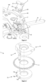
- a first embodiment of a timepiece 1000 is described below with reference to the Figures 1 to 14 .
- the timepiece 1000 is for example a watch, in particular a wristwatch.
- the 1000 timepiece comprises a 900 watch movement intended to be mounted in a timepiece case or box in order to protect it from the external environment.
- this third stud 23 of the first pull tab 2 is also capable of cooperating with the oblong cutout 31 of the second pull tab 3.
- the first adjustment chain could be an adjustment chain (in particular bidirectional adjustment) of a time zone indication and the second adjustment chain could be an adjustment chain (in particular unidirectional adjustment) of a date indication.
- FIG 2 illustrates a part of the winding kinematic chain 300 made operational thanks to the first configuration C1 of the function selection device 200, when the control stem 1 is located in the first position P1.
- This winding kinematic chain 300 here comprises a vertical clutch device comprising a first crown wheel 301 meshing with a winding pinion 10 mounted square on the control stem 1.
- This first crown wheel 301 is also capable of meshing with a second crown wheel 302 depending on the state of the vertical clutch device, controlled by the axial position of the control stem 1 along the axis A1.
- a sliding shaft 303, integral with the second crown wheel 302, is located at the bottom of a second groove 1b of the control stem 1 thanks to the support of a return spring 304.
- the first wheel 301 and the second wheel 302 control rods are then engaged with each other, thus allowing manual winding of the movement.
- the control rod 1 is in the other positions P2 and P3, the sliding axis 303 is outside the second groove 1b, thus disengaging the second crown wheel 302 from the first crown wheel 301.
- Such a vertical clutch device is for example described in the document WO2012175595 .
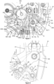
- the first adjustment chain 400 is capable of being engaged by a first toothing 11a of a sliding pinion 11 mounted square on the control stem 1. More precisely, when the control stem 1 is in the second position P2, the sliding pinion 11 is placed by a lever 12 pivoted on the frame 100 and controlled by the control wheel set 7 so that the toothing 11a of the sliding pinion 11 can mesh with a third front toothing 401a of a first pinion 401 of the first adjustment chain 400.
- This first pinion is provided to drive a corrector wheel set 404 via a wheel set 403. According to the invention as claimed, this corrector wheel set 404 has the particularity of being pivoted on a lever 402 controlled by a lever 14 of the clockwork mechanism 800.
- the control mobile 7 which includes a control cam, comprises a third profile 73 and a fourth profile 74 capable of cooperating with the rockers 12, 14 respectively.
- a return spring 13 and a return spring 15 tend respectively to return these rockers 12, 14 towards these third and fourth profiles 73, 74 of the control mobile 7 with which they are capable of cooperating.
- the third profile 73 of the mobile 7 allows the rocker 12 to be released under the effect of the spring 13, in order to allow the sliding pinion 11 to engage the first adjustment chain 400.
- the fourth profile 74 of the mobile 7 makes it possible to control the rocker 14 in cooperation with the spring 15, in order to allow the positioning of the rocker 402.
- the cooperation of the rocker 14 and the rocker 402 is carried out here in particular by means of a first pin 14a of the rocker 14, which cooperates by contact with a cam profile 402a of the rocker 402.
- the position of the flip-flop 14 determines the position or configuration of the flip-flop 402.
- the flip-flop 14 and the flip-flop 402 are configured and/or arranged so as to position the flip-flop 402 according to a first angular position and a second angular position around its axis 402e, the first angular position making it possible to activate a first correction function, in particular a function for correcting the date indication, and the second angular position making it possible to deactivate the first correction function.
- the flip-flop 14 and the flip-flop 402 are configured and/or arranged so as to position the flip-flop 402 in a third angular position around its axis 402e, making it possible to activate a second correction function, in particular a function for correcting the indication of days.
- the flip-flop 14 and the flip-flop 402 are configured and/or arranged such that, in the second angular position, the second correction function is deactivated.
- the first desmodromic cam link element is a stud 14a or a pin and the second desmodromic cam link element cam is a cam profile 402a.
- the first desmodromic cam linkage member could be a cam profile and the second desmodromic cam linkage member could be a stud or a pin.
- the corrector wheel 404 comprises a corrector 406 for indicating the dates, as well as a toothed wheel 405 integral in rotation with the corrector 406.
- the cooperation of the elements 14 and 74 makes it possible to position the corrector 406 of the corrector wheel 404 in the teeth of a date disc 600 (as shown in FIG. figure 7 ) or to position the toothed wheel 405 of the corrector wheel 404 in the teeth of a star 700 of the day display (as shown in the figure 11 ) or to disengage the corrector mobile 404 from any adjustment function (as shown in the figures 5 , 9 And 13 ).
- the rocker 402 comprises at least one arm 402c and the first friction element 402b comprises at least one friction surface 402f, the at least one arm 402c being arranged so as to elastically return the at least one friction surface 402f against the corrective mobile 404.
- rocker 402 illustrated in particular by the figure 5
- the latter is more specifically provided with the two elastically deformable arms 402c each comprising two bearing surfaces 402f cooperating by contact with the portion 404a of the corrective mobile preferably having a cylindrical shape.
- the friction element 402b is thus implemented by means of two elastically deformable arms each comprising two bearing surfaces 402f cooperating by contact with the portion 404a of the corrective mobile.
- the friction element 402b applies at least one radial or substantially radial force (except for the effects of the friction coefficient) on portion 404a of the corrective mobile.
- the four bearing surfaces 402f define a housing allowing the engagement of the portion 404a of the corrective mobile within the rocker 402.
- the bearing surfaces 402f are equally distributed around the portion 404a of the corrective mobile 404, that is to say that the angular interval between any neighboring bearing surfaces is identical or substantially identical.
- the element 402d for guiding the rotation of the corrective wheel 404 is implemented by the bearing surfaces 402f cooperating by contact with the portion 404a of the corrective wheel.
- the element 402d for guiding the rotation of the corrective wheel 404 and the friction element 402b are merged or formed by the same element.
- the rocker 402 is a single piece.
- the rocker 402 can for example be obtained by cutting from a plate or by electroforming techniques such as LIGA.
- the thickness of the scale 402 or the thickness footprint of the scale can be reduced.
- the thickness or thickness footprint can be less than 200 ⁇ m or less than 150 ⁇ m.
- the friction torque generated by the friction element 402b acting on the portion 404a of the corrective wheel assembly allows the lever 402 and its corrective wheel assembly to pivot around the rotational guiding element 402e of the lever 402, and this according to the direction of rotation of the adjustment chain 400.
- each reversal of the direction of rotation applied to the adjustment chain is likely to generate a rotation of the lever 402 under the effect of the rotation of the corrective wheel assembly.
- This rocker 402 here has the particularity of comprising the profile 402a, in the form of a groove, which is intended to cooperate with the stud 14a of the rocker 14.
- the groove 402a is provided with three distinct portions 1402a, 2402a, 3402a. The cooperation between the elements 14a and 402a makes it possible to define at least three angular positions of the rocker 402 around the guide element 402e.
- the stud 14a makes it possible to lock the angular position of the lever 402 so that the correcting wheel set 404 can perform a bidirectional adjustment of the date indication (as visible in the figure). figure 7 ).
- the stud 14a of the rocker 14 is located at the level of the first portion 1402a of groove 402a.
- This first portion comprises two parallel or substantially parallel flanks arranged on either side of the stud 14a, which prevent any untimely rotation of the rocker 402 about its axis 402e with the clearance between the stud and the flanks, the distance between the two flanks corresponding to the diameter of the stud with the clearance.
- each of these flanks forms an angle of the order of 90° opposite a segment defined by a first point passing through the pivot axis A14 of the rocker 14 and a second point passing through the center of the stud 14a.
- the flanks are arranged orthoradially or substantially orthoradially opposite the axis A14.
- Each of these flanks also forms a non-zero angle (for example substantially 90°) with the direction orthoradially to the axis 402e.
- Such a conformation prevents any untimely rotation of the rocker 402 around the axis 402e under the effect of the elements 402b, 402c, 402d potentially actuated by a rotation of the mobiles 401, 403, 404 around their respective axis.
- the rocker 14, under the effect of its return spring 15 is positioned in a hollow formed within the profile 74 of the control mobile 7 connected to the second pull rod 3.
- the stud 14a makes it possible to position the rocker 402 while giving it a degree of freedom in rotation so as to allow the correcting wheel set 404 to perform a one-way adjustment of the day indication (as visible in the figure). figure 11 ).
- the stud 14a is arranged within a third portion 3402a of groove 402a.
- This third portion 3402a comprises flanks shaped and oriented in such a way that the latter allow a rotation of the lever 402 about the axis 402e over a given angular range, so that the latter is capable of reaching an angular position allowing the wheel 405 to mesh with the day indicator wheel 700 under the effect of the elements 402b, 402c, 402d potentially actuated by a rotation of the mobiles 401, 403, 404 about their respective axes. More particularly, the distance between two flanks of the third portion 3402a, in a direction orthoradial to the axis 402e, is greater than the diameter of the stud 14a. For example, this distance is of the order of three times the diameter of plot 14a.
- the position of the lever 402, still defined by the pin 14a, is such that the corrector wheel 404 is out of range of the date or day indicators (as visible on the figures 5 , 13 ).
- the stud 14a of the rocker 14 is located at the level of the second portion 2402a of groove 402a.
- This second portion comprises two parallel or substantially parallel flanks arranged on either side of the stud 14a, which prevent any untimely rotation of the rocker 402 about its axis 402e, excluding the clearance between the stud and the flanks, the distance between the two flanks corresponding to the diameter of the stud excluding the clearance.
- Each of these flanks forms an angle of the order of 45° with respect to a segment defined by a first point passing through the axis A14 and a second point passing through the center of the stud 14a.
- Each of these flanks also forms a non-zero angle with the direction orthoradial to the axis 402e.
- the rocker 14 has the particularity of being held in position against its return spring 15 by the pull rod 2, in particular by the profile 24 of the pull rod 2, the latter being positioned by the control rod 1, itself positioned according to the first axial position P1.
- the second pull tab 3 is, for its part, held in position by the second indexing device 5. More particularly, it is held in position by the second functional surface 52 which cooperates here with a first indexing notch 72a of the third functional surface 72 of the mobile 7.
- the snap-fastening member 6 is released from the path of the third stud 23. More particularly, the respective conformations of the fourth stud 63 and the profile of the cutout 99 of the frame 100 make it possible to keep the beak 61 out of reach of the third stud 23.
- the sliding pinion 11 is here recalled by the lever 12 against a bearing surface of the control rod 1 so that it is disengaged from any adjustment chain, while the lever 14 is held in position by the first pull rod 2 by means of a second profile 24.
- the lever 402 is positioned by the lever 14 so that the corrector wheel set 404 is out of range of the date disc and the day display star.
- control mobile 7 and the latching member 6 have remained stationary, and the latter remains out of range of the trajectory of the third stud 23.
- the axial movement of the control rod 1 in the first direction D1 causes the disengagement of the winding kinematic chain 300, and the engagement of the first adjustment chain 400.
- the movement of the rocker 12, under the effect of the spring 13, is possible here, because the third profile 73 is here shaped so as to leave it this degree of freedom.
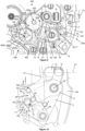
- the lever 14 is no longer retained by the second profile 24 of the first pull-out 2, which allows it to position the lever 402 in a stable angular position around the axis 402e, which is characterized by the fact that the corrector 406 is arranged in the teeth of the date disc 600, in particular at its original diameter.
- the movement of the lever 14 is possible here because the profile 74 is shaped so as to leave it this degree of freedom.
- the toothing 11a of the sliding pinion 11 meshes with the front toothing 401a of the pinion 401 of the first adjustment chain 400.
- This first pinion drives the correcting wheel set 404 via the wheel set 403 pivoted around the axis 402e.
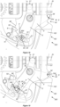
- the transient, unstable state in which the control rod 1 is temporarily in the third position P3 is illustrated by the Figures 9 and 10 .
- This unstable position of the control rod 1 makes it possible to configure the function selection device 200 so as to allow one-way adjustment of the day indication.
- the first pull rod 2 drives the second pull rod 3 which then drives the control wheel 7.
- the third stud 23 of the first pull rod 2 which acts against a first end of the oblong cutout 31 of the second pull rod 3, the latter already being arranged at this first end according to the second configuration C2.
- the second pull tab 3 is held in its new position by means of the second indexing device 5. More particularly, the second pull tab 3 is held in its new position by the second functional surface 52 cooperating here with a second indexing notch 72b of the third functional surface 72 of the mobile 7, the latter being connected to the second pull tab 3 by means of the gear connection 33, 71.
- the second pull rod 3 is in a stable position defined by the second indexing device 5.
- the first pull tab 2 is also in an unstable position, the position of the latter not being defined by the first indexing device 4. More particularly, the second stud 22 of the first pull tab 2 is located on a third flank 42c of the first spring 41, which tends to return the control rod 1 to the second position P2, in the hollow of the second flank 42b, after the user has released the control rod 1. After this last action, the function selection device 200 is then configured according to the third configuration C3. This configuration is illustrated by the Figures 11 and 12 .
- the third stud 23 of the first pull tab 2 pushes back the fourth flank 61a of the beak 61 of the latching member 6.
- This latching member 6 can thus fold back and allow the third stud 23 to pass on the other side of the beak 61.
- the stud 23 is thus locked between a fifth flank 61b of the beak 61 and a second end of the oblong cutout 31.
- the first and second pull tabs are then secured in rotation. Any relative rotational movement between the first and second pull tabs is therefore impossible.
- the first and second pull rods are thus indexed in a stable position by the second indexing device 5.
- the control rod 1 is also indexed in a stable position by the second indexing device 5.
- the flip-flop 12 here maintains its position as defined by the second configuration C2, which allows to the sliding pinion 11 to remain engaged with the first adjustment chain 400.
- the profile 74 of the control wheel 7 actuates the lever 14 so that the latter configures the lever 402 so as to allow the adjustment of the days.
- this allows the wheel 405 of the corrector wheel 404 to perform a one-way adjustment of the indication of the days by meshing with the teeth of the wheel 700 of the days.
- the sliding pinion 11, the first pinion 401, the mobile 403 and the correcting mobile 404 remain meshed. Only the position of the lever 14 is modified under the effect of the rotation of the control mobile 7, which is controlled by a back-and-forth movement of the control rod 1 allowing the mechanism to switch from the second configuration C2 to the third configuration C3. More particularly, in this third configuration, the lever 14 is positioned by a projection formed at the profile 74 of the control mobile 7.
- a new pull on the control rod 1 in the first direction D1 allows the control rod 1 to reach the third stable position P3, and sets the function selection device 200 according to the fourth configuration C4.
- This configuration is illustrated by the Figures 13 and 14 .
- the second pull tab 3 is then held in a new stable position by the second indexing device 5. More particularly, the second functional surface 52 cooperates here with a third indexing notch 72c of the third functional surface 72 of the mobile 7.
- first pull tab 2 is also held in a stable position by means of the second indexing device 5, while the second pull tab stud 22 is still located on the third flank 42c of the first spring 41.
- the rocker 12 is actuated by the profile 73 so that the sliding pinion 11 can engage the second adjustment chain 500.
- the lever 14 is actuated by the profile 74 so that the lever 402 is positioned so that the corrector wheel 404 is out of range of the teeth of the date disc and that of the star of the days of the week.
- the movement can therefore be set to the correct time by the user.
- the fourth configuration C4 is distinguished from the first configuration by the fact that the rocker 14 is held in position not by the profile 24 of the pull rod 2, but by a profile 74 of the control mobile 7 kinematically linked to the second pull rod 3, the latter being previously positioned by the control rod 1, itself positioned according to the third axial position P3 by means of the first pull rod 2.
- the first pull rod 2 simply reconfigures itself according to the first configuration C1. More particularly, the second pull rod stud 22 passes from the second flank 42b to the first flank 42a of the first spring 41.
- control rod 1 Returning the control rod 1 to position P1 allows the winding drive chain 300 to be re-engaged. At the same time, the control rod 1 also disengages the sliding pinion 11 of the first adjustment chain 400.
- the first pull rod 2 pushes back the lever 14, thus ensuring that the corrector wheel 404, pivoted on the lever 402, is out of range of the teeth of the date disc and that of the day star.
- control rod 1 By pushing the control rod 1 in the second direction D2, the latter simultaneously drives the first and second pull rods 2, 3 so as to reconfigure the function selection device 200 according to the first configuration C1.
- the third stud 23 is in abutment in the oblong cutout 31.
- the second configuration C2 cannot be selected by pushing the control rod 1 in the second direction D2. Only the third and first configurations C3 and C1 can be reached by pushing the control rod 1.
- the relative position of the first and second pull tabs 2, 3 is identical to that known from the third configuration C3.
- the kinematics of the pull tabs 2, 3 when returning to the first configuration C1 from the fourth configuration C4 is therefore substantially identical to that known from the third configuration C3.
- the control rod 1 thus drives the first pull tab 2 which drives the second pull tab 3 thanks to the third stud 23 in contact with the oblong cutout 31.
- the beak 61 of the snap-fastening member 6 is released from the path of the third stud 23 thanks to the cooperation of the fourth stud 63 with the profile of the cutout 99.
- a second embodiment of a 1000' timepiece is described below with reference to Figures 15 to 21 .
- the second embodiment differs from the first embodiment only in part of its characteristics.
- references of elements of the second embodiment are deduced from those of elements of the first embodiment (having identical or substantially identical structures and/or identical or substantially identical functions) by the addition of an apostrophe “ '”.
- the 1000' timepiece is for example a watch, in particular a wristwatch.
- the 1000' timepiece includes a 900' watch movement intended to be mounted in a timepiece case or box in order to protect it from the external environment.
- the 900' watch movement can be an electronic movement or a mechanical movement, including an automatic movement.
- the 900' watch movement includes an 800' watch mechanism.
- This second embodiment differs mainly from the first by the arrangement of the snap-in member as well as by the device for selecting the different winding and adjustment chains, which has the particularity of not including a control wheel.
- the second embodiment differs from the first embodiment in that the second position indexing device 5' comprises a second spring 51' provided with a second functional surface 52' (forming a double beak) and a fifth stud 34' secured to the second pull rod 3'.
- the cooperation of the second functional surface 52' with the fifth stud 34' makes it possible to define the three stable angular positions of the second pull rod 3'.
- the snap-fastening member 6' of this second embodiment comprises a fourth functional surface 63' instead of a stud.
- This fourth functional surface is intended to cooperate with the profile formed by the periphery of the cutout 99' of the frame 100'.
- the kinematics of this snap-fastening member, as well as those of the components with which it is capable of cooperating, are identical to those known from the first embodiment.
- the control of the two levers 12', 14' of this second embodiment is not carried out here by means of a control mobile. It is directly the first and second pull rods 2', 3' which control them. Nevertheless, the different winding and adjustment chains have a similar operation to that known from the first embodiment. Moreover, as for the first embodiment, a second profile 24', or more particularly here a sixth stud 24' is also capable of cooperating with the lever 14'.
- this second embodiment also has the particularity of having the second pad 22', the third pad 23' and the sixth pad 24' arranged coaxially.
- the function selection device 200' allows the selection of the different functions of the clock mechanism 800' by means of a first pull tab 2' and a second pull tab 3' (as shown in the figure 16 ) which can conform respectively according to four distinct configurations C1, C2, C3 and C4 defined by three axial positions P1, P2 and P3 of the control interface element 1.
- FIG 17 illustrates the function selection device 200' according to the first configuration C1.
- FIG 18 illustrates the function selection device 200' according to the second configuration C2.
- FIG 19 illustrates the transient, unstable state in which the control rod 1 of the function selection device 200' is temporarily in the third position P3, when changing from the second configuration C2 to the third configuration C3.
- FIG 20 illustrates the 200' function selection device according to the third configuration C3.
- FIG 21 illustrates the 200' function selection device according to the fourth configuration C4.
- a method of executing a method of operating a device for selecting watch functions as mentioned above or a watch mechanism as mentioned above or a watch movement as mentioned above or a timepiece as mentioned above is described below.
- the selection device 200; 200' is configured according to a third configuration C3 when the interface element 1 is moved from the third stable position P3 to the second intermediate stable position P2.
- the first position P1 of the interface element 1 defines the first configuration C1 of the function selection device 200; 200'. From this first position P1, when the user pulls the interface element 1 in the first direction D1, the latter reaches the second position P2, thus conforming the function selection device 200; 200' according to the second configuration C2.
- the selection device 200; 200' of functions according to the fourth configuration C4 it is first necessary for it to be configured according to the third configuration C3.
- a new pull on the interface element 1 makes it possible to conform the selection device 200; 200' according to the fourth configuration C4.
- the interface element 1 reaches the third position P3 which is stable here.
- the third stable position P3 of the interface element 1 therefore defines the fourth configuration C4 of the selection device. From this third and final position P3, by pushing the interface element 1 to the second position P2, the selection device 200; 200' can only be reconfigured into the third configuration C3.
- each pull performed on the interface element 1 makes it possible to successively select the different configurations of the selection device according to the predefined order C1, C2, C3 and C4.
- the selection device 200; 200' can only be shaped according to the fourth configuration C4 corresponding to the time setting function after having performed a manipulation of the interface element 1 characterized by a back-and-forth movement, which prevents the user from stopping the movement unexpectedly in the case where the mechanism is equipped with a "seconds stop” or a "balance stop".
- control interface controlling the mechanism or the selection device allowing the selection of the different functions or configurations of the selection device taking part in said mechanism are identical regardless of the embodiment or the embodiment variant.
- the function selection device makes it possible to make operational the different chains of the watch mechanism allowing respectively the winding and the adjustments of the different functions of the watch.
- These chains are for example identical or substantially identical regardless of the embodiment.
- the selection devices are used to select particular timepiece functions.
- a selection device according to the invention can be used to select any desired timepiece functions that can be arranged within a timepiece. These can be timepiece functions, in particular time or calendar functions or functions derived from the time. They can also be control or adjustment functions, for example a chime.
- the number of positions of the indexing element is three and the number of configurations of the selection device is four.
- these numbers can be modified, in particular increased.
- it would be entirely possible to construct a variant of the selection device comprising an additional position for the interface element 1, which would allow at least one additional new configuration to be defined.
- This additional position could, for example, be reached by pulling the interface element 1 once again from the third position P3.
- the relative movement of the two pull tabs is locked in this third position P3.
- An additional pull of the interface element 1 would thus allow the second pull tab 3; 3' to be indexed by the second indexing device 5; 5' according to a new angular position.
- the third flank 42c; 42c' would just have to be extended to allow it to reach this new angular position.
- the two configurations C2, C3 here selectable when the interface element 1 is arranged in the second position P2 could of course be defined by any other axial position of the interface element.
- the mechanism could also comprise at least two axial positions of the interface element for which two configurations are selectable.
- first indexing device 4; 4' it is possible to shape the third flank 42c; 42c' so that it does not tend to bring the first pull tab 2; 2' back into the hollow of the second flank 42b; 42b'.
- another elastic element could be capable of bringing said pull tab back into the hollow of the second flank 42b; 42b'.
- the fifth spring 62; 62' for returning the latching member 6; 6' could also be alternately supported on the frame 100; 100' instead of being supported on the first or second pull tab. Conversely, the fifth spring 62; 62' could also be embedded in the frame 100; 100' and press on the latching member 6; 6'.
- the latching member 6; 6' could simply be in the form of a flexible element or a built-in spring, which could for example be included in said pull tab. This spring should then have a conformation acting as a beak capable of cooperating with the frame 100; 100' and the first pull tab 2; 2'.
- first and second pull tabs are arranged coaxially.
- these pull tabs could not be arranged in this way.
- the second pull tab 3; 3' can thus be likened to a pivoted rocker, whether or not it is arranged coaxially with the first pull tab 2; 2'.
- the selection of the third configuration C3 requires that the interface element 1 be pulled from the second position P2 to the third position P3, here unstable, then released by the user, so that it can return to the second position P2.
- the so-called unstable position is not exactly on the third position P3. Indeed, it could very well be before or after this third position P3.
- the amplitude of this back-and-forth movement of the interface element 1 must just be sufficient so that the latching member 6; 6' can lock the relative movement of the two pull tabs at the end of this action.
- the watch mechanism 800; 800' could comprise as many winding and/or adjustment chains as there are configurations selectable by the function selection device 200; 200'.
- each selection of a given configuration could correspond to the clutch of a specific and dedicated winding or adjustment chain.
- the clock mechanism 800; 800' could comprise a manual winding chain which could be engaged not by a vertical clutch, but by means of a sliding pinion integral in rotation with the control stem and capable of moving in the direction of the control stem.
- a control stem 1 acts as an interface element on the first pull 2; 2' which is directly engaged with the interface element 1.
- the first pull 2; 2' could be connected indirectly to the interface element 1, for example by means of one or more rockers or stems.
- the selection of functions could be done by means of a crown arranged on a secondary stem parallel to the interface element 1, by means of a means kinematically connecting the two stems. This type of arrangement is found in particular in constructions in which it is necessary to offset the position of the crown relative to that of the stem of the movement.
- the selection could be made using a crown arranged on a secondary rod parallel to the axes of the needles, by means of a means making it possible to control the translation of a rod similar to that of the interface element 1 described in this document by the translation of this alternative interface means.
- this function selection device could also be done using another interface means, such as, for example, a rotating bezel.
- the elements of the first and second indexing devices 4; 4', 5; 5' may be shaped according to any geometries so as to allow the stable positioning of the pull device 150; 150' comprising the first and second pulls 2; 2', 3; 3'.
- the elements of the first and second indexing devices 4; 4', 5; 5' may of course be shaped according to any geometries so as to allow the stable positioning of the first pull 2; 2' for at least a first stable position of the interface element 1 and to allow the stable positioning of the second pull 3; 3' for at least a second stable position of the interface element 1.
- pull tab preferably means a rocker whose position is controlled by an interface element, in particular a control rod, directly for example by means of a pull tab stud and cooperating with a groove made on the control rod.
- the term “pull tab” preferably also means a rocker whose position is controlled directly by the action of another pull tab.
- top view means a view from the face of the movement located on the dial side.
- indexing an element By “indexing an element”, “angular indexing of an element” or “positional indexing of an element” is meant the definition of different stable positions of an element. These stable positions can be separated by a continuum of intermediate unstable positions. Between two stable positions or two positions indexed or two indexing positions, the element passes transiently through a continuum of unstable or less stable intermediate positions.
- stable position is meant a given position of the interface element 1, of the first pull tab or of the second pull tab (or rocker), once the interface element 1 has been released by the user.
- stable axial position is meant a given axial position of the interface element 1 once the latter has been released by the user.
- This “stable position” is defined by the first indexing device 4; 4' and/or by the second indexing device 5; 5'.
- stable position is meant a given position of the interface element 1 which is exclusively defined by a maintained action of a user. Once the interface element 1 is released, the latter returns to a stable position, different from the unstable position.
- pull rod device 150; 150' we mean a device comprising at least two pivoted rockers connected to each other and movable relative to each other.
- a first rocker 2; 2' may meet the definition of "pull rod", the latter being in direct engagement with a control rod.
- a second rocker 3; 3' may also meet the definition of pull rod knowing that the latter has a conformation substantially equivalent to that of the first rocker 2; 2', and that this second rocker 3; 3' is pivoted coaxially to the first rocker 2; 2'.
- this second rocker is not necessarily pivoted coaxially to the first rocker.
- configuration of the function selection device refers to a very specific arrangement or conformation. elements taking part in the mechanism, allowing the winding and/or adjustment chains to be made operational or engaged.
- quential mechanism we mean here a mechanism capable of selecting different configurations of a selection device for the same stable position of a control member.
- the device according to the invention can be described as a “semi-sequential” mechanism, knowing that it allows both the selection of different configurations of a selection device by moving an interface element between various stable positions, and at least one configuration of said selection device by a back-and-forth movement of the interface element, in particular from a given stable position to this same stable position.
- a stud of an element preferably consists of a finger extending perpendicularly or substantially perpendicularly to a plane along which the remainder of the element extends.
- a stud is constituted by a pin or a dowel.
- the cooperation of the first and second desmodromic connecting elements makes it possible in particular to configure the selection device from one given configuration to another.
- it makes it possible, when changing from one configuration to another, to move the rocker 402 according to different angular positions under the effect of the movement of the rocker 14, and this independently of any return spring.
- desmodromic linkage we mean a linkage arranged so as to allow the position of the second rocker 402 to be defined from the position of the first rocker 14 without using a return spring of the second rocker against the first rocker.
- This desmodromic linkage makes it possible to define, in a unique manner, a position of the second rocker for each of several positions of the first rocker.
- a movement of the flip-flop 402 carried out independently of the movement of the flip-flop 14 is nevertheless possible, in particular when the selection device is configured according to the third configuration C3.
- the first and second desmodromic connecting elements are arranged such that they allow the flip-flop 402 to be positioned according to a third angular position.
- the solutions described enable rapid adjustments of several display functions, including several display functions of a calendar.
- the solutions described enable rapid, bidirectional adjustment of a date indication, as well as adjustment of a weekday indication.
Landscapes
- Physics & Mathematics (AREA)
- General Physics & Mathematics (AREA)
- Electric Clocks (AREA)
- Saccharide Compounds (AREA)
Claims (15)
- Uhrmechanismus (800; 800') zur Korrektur einer Uhrfunktion, welcher umfasst:- eine erste Wippe (14), die ein erstes desmodromisches Nockenverbindungselement (14a) umfasst,- einen Korrekturdrehteil (404) und- eine zweite Wippe (402),wobei die zweite Wippe (402) umfasst:- mindestens ein erstes Führungselement (402d) des Korrekturdrehteils (404),- mindestens ein erstes Reibelement (402b), das am Korrekturdrehteil (404) anliegt, und- ein zweites desmodromisches Nockenverbindungselement (402a), das dazu vorgesehen ist, durch Kontakt mit dem ersten desmodromischen Nockenverbindungselement (14a) zusammenzuwirken,wobei das mindestens eine erste Führungselement (402d) und das mindestens eine erste Reibelement (402b) zusammenfallen oder von demselben Element gebildet werden, dadurch gekennzeichnet, dass die zweite Wippe einstückig ist, und dadurch, dass der Korrekturdrehteil (404) an der zweiten Wippe (402) drehbar angebracht ist.
- Mechanismus nach dem vorhergehenden Anspruch, dadurch gekennzeichnet, dass das erste desmodromische Nockenverbindungselement ein Klötzchen (14a) ist und das zweite desmodromische Nockenverbindungselement ein Nockenprofil (402a) ist, oder dadurch, dass das erste desmodromische Nockenverbindungselement ein Nockenprofil ist und das zweite desmodromische Nockenverbindungselement ein Klötzchen ist.
- Mechanismus nach dem vorhergehenden Anspruch, dadurch gekennzeichnet, dass das Nockenprofil (402a) aus einer Nut (402a) besteht, die mit mindestens zwei verschiedenen Abschnitten (1402a, 2402a) oder sogar drei verschiedenen Abschnitten (1402a, 2402a, 3402a) versehen ist.
- Mechanismus nach einem der vorhergehenden Ansprüche, dadurch gekennzeichnet, dass die zweite Wippe (402) mindestens einen Arm (402c) umfasst, und dadurch, dass das erste Reibelement (402b) mindestens eine Reibfläche (402f) umfasst, wobei der mindestens eine Arm (402c) dafür ausgebildet ist, die mindestens eine Reibfläche (402f) elastisch gegen den Korrekturdrehteil (404) vorzuspannen.
- Mechanismus nach einem der vorhergehenden Ansprüche, dadurch gekennzeichnet, dass die zweite Wippe eine Dicke aufweist, die kleiner als 200 µm oder sogar kleiner als 150 µm ist.
- Mechanismus nach einem der vorhergehenden Ansprüche, dadurch gekennzeichnet, dass die erste Wippe (14) und die zweite Wippe (402) dafür ausgebildet und/oder eingerichtet sind, die zweite Wippe (402) in einer ersten Winkelposition und einer zweiten Winkelposition um eine Drehachse (402e) der zweiten Wippe (402) zu positionieren, wobei die erste Winkelposition ermöglicht, eine erste Korrekturfunktion zu aktivieren, insbesondere eine Korrekturfunktion der Datumsanzeige, und die zweite Winkelposition ermöglicht, die erste Korrekturfunktion zu deaktivieren.
- Mechanismus nach einem der vorhergehenden Ansprüche, dadurch gekennzeichnet, dass die erste Wippe (14) und die zweite Wippe (402) dafür ausgebildet und/oder eingerichtet sind, die Positionierung der zweiten Wippe (402) in einer dritten Winkelposition um ihre Achse (402e) zu ermöglichen, die es gestattet, eine zweite Korrekturfunktion zu aktivieren, insbesondere eine Korrekturfunktion der Tagesanzeige.
- Mechanismus nach den Ansprüchen 6 und 7, dadurch gekennzeichnet, dass die erste Wippe (14) und die zweite Wippe (402) so ausgebildet und/oder eingerichtet sind, dass in der zweiten Winkelposition die zweite Korrekturfunktion deaktiviert wird.
- Mechanismus nach einem der vorhergehenden Ansprüche, dadurch gekennzeichnet, dass der Mechanismus eine Auswahlvorrichtung (200) umfasst, die eine Stellhebelvorrichtung (150) umfasst, die einen Stellhebel (2) und eine dritte Wippe (3) aufweist, und dadurch, dass die erste Wippe (14) von der Auswahlvorrichtung (200) gesteuert wird, wobei die Stellhebelvorrichtung (150) und die erste Wippe (14) so ausgebildet und/oder eingerichtet sind, dass die erste Wippe (14) von dem Stellhebel (2) oder von einem Profil (74) eines Steuerdrehteils (7), der mit der dritten Wippe (3) kinematisch verbunden ist, positioniert wird.
- Mechanismus nach Anspruch 9, dadurch gekennzeichnet, dass der Mechanismus ein Schnittstellenelement (1) umfasst, und dadurch, dass der Mechanismus so eingerichtet ist, dass, wenn die Auswahlvorrichtung (200) in einer ersten Konfiguration (C1) konfiguriert ist, die einer ersten axialen Position (P1) des Schnittstellenelements (1) entspricht, die zweite Wippe (402) sich in der zweiten Winkelposition befindet, in der die erste und die zweite Korrekturfunktion deaktiviert sind.
- Mechanismus nach einem der Ansprüche 9 und 10, dadurch gekennzeichnet, dass der Mechanismus ein Schnittstellenelement (1) umfasst, und dadurch, dass der Mechanismus so eingerichtet ist, dass, wenn die Auswahlvorrichtung (200) in einer zweiten Konfiguration (C2) konfiguriert ist, die einer zweiten axialen Position (P2) des Schnittstellenelements (1) entspricht, die zweite Wippe (402) die erste Winkelposition aufweist, in der die erste Korrekturfunktion aktiviert ist.
- Mechanismus nach einem der Ansprüche 9 bis 11, dadurch gekennzeichnet, dass der Mechanismus ein Schnittstellenelement (1) umfasst, und dadurch, dass der Mechanismus so eingerichtet ist, dass, wenn die Auswahlvorrichtung (200) in einer dritten Konfiguration (C3) konfiguriert ist, die der zweiten axialen Position (P2) des Schnittstellenelements (1) entspricht, die zweite Wippe (402) eine dritte Winkelposition aufweisen kann, in der die zweite Korrekturfunktion aktiviert ist.
- Mechanismus nach einem der Ansprüche 9 bis 12, dadurch gekennzeichnet, dass der Mechanismus ein Schnittstellenelement (1) umfasst, und dadurch, dass der Mechanismus so eingerichtet ist, dass, wenn die Auswahlvorrichtung (200) in einer vierten Konfiguration (C4) konfiguriert ist, die einer dritten axialen Position (P3) des Schnittstellenelements (1) entspricht, die zweite Wippe (402) sich in der zweiten Winkelposition befindet, in der die erste und die zweite Korrekturfunktion deaktiviert sind.
- Uhrwerk (900; 900'), welches einen Uhrmechanismus (800; 800') nach einem der vorhergehenden Ansprüche umfasst.
- Uhr (1000; 1000'), welche einen Uhrmechanismus nach einem der Ansprüche 1 bis 13 und/oder ein Uhrwerk nach dem vorhergehenden Anspruch umfasst.
Priority Applications (4)
| Application Number | Priority Date | Filing Date | Title |
|---|---|---|---|
| EP21160830.2A EP4053639B1 (de) | 2021-03-04 | 2021-03-04 | Vorrichtung zur auswahl von uhrfunktionen |
| US17/684,389 US12332602B2 (en) | 2021-03-04 | 2022-03-01 | Timepiece mechanism |
| JP2022031483A JP2022136011A (ja) | 2021-03-04 | 2022-03-02 | 時計機能選択用装置 |
| CN202210213968.7A CN115016238A (zh) | 2021-03-04 | 2022-03-04 | 钟表机构 |
Applications Claiming Priority (1)
| Application Number | Priority Date | Filing Date | Title |
|---|---|---|---|
| EP21160830.2A EP4053639B1 (de) | 2021-03-04 | 2021-03-04 | Vorrichtung zur auswahl von uhrfunktionen |
Publications (2)
| Publication Number | Publication Date |
|---|---|
| EP4053639A1 EP4053639A1 (de) | 2022-09-07 |
| EP4053639B1 true EP4053639B1 (de) | 2025-01-01 |
Family
ID=74859220
Family Applications (1)
| Application Number | Title | Priority Date | Filing Date |
|---|---|---|---|
| EP21160830.2A Active EP4053639B1 (de) | 2021-03-04 | 2021-03-04 | Vorrichtung zur auswahl von uhrfunktionen |
Country Status (4)
| Country | Link |
|---|---|
| US (1) | US12332602B2 (de) |
| EP (1) | EP4053639B1 (de) |
| JP (1) | JP2022136011A (de) |
| CN (1) | CN115016238A (de) |
Families Citing this family (1)
| Publication number | Priority date | Publication date | Assignee | Title |
|---|---|---|---|---|
| EP4481509A1 (de) * | 2023-06-20 | 2024-12-25 | Rolex Sa | Zuglaschenmechanismus |
Family Cites Families (23)
| Publication number | Priority date | Publication date | Assignee | Title |
|---|---|---|---|---|
| CH520968A (fr) | 1970-07-13 | 1972-03-31 | Omega Brandt & Freres Sa Louis | Montre à quantième munie d'un correcteur de l'indicateur de quantième |
| CH584926B5 (de) | 1971-10-06 | 1977-02-15 | Suisse Horlogerie | |
| CH1576671A4 (de) | 1971-10-29 | 1975-10-31 | ||
| US3890778A (en) * | 1973-08-02 | 1975-06-24 | Ebauches Sa | Watch stem intermediate setting position with functions determined by whether intermediate position was achieved by pushing stem in or pulling stem out |
| JPS52156664A (en) * | 1976-06-21 | 1977-12-27 | Seiko Epson Corp | Calendar correcting mechanism |
| CH645235GA3 (de) | 1981-04-23 | 1984-09-28 | ||
| EP1939699B1 (de) | 2006-12-29 | 2012-05-30 | Montres Breguet S.A. | Multifunktionsvorrichtung zur koaxialen Korrektur |
| DE602008004125D1 (de) * | 2008-06-17 | 2011-02-03 | Montres Breguet Sa | Anzeigevorrichtung zum Anzeigen der einen oder anderen von zwei verschiedenen Angaben mit demselben Anzeigeelement einer Uhr |
| CH702548B1 (fr) | 2010-01-11 | 2014-07-15 | Richemont Int Sa | Mécanisme de sélection de fonction pour mouvement d'horlogerie comportant au moins une complication. |
| EP2362277B1 (de) * | 2010-02-25 | 2012-10-31 | Montres Breguet SA | Zeitzone auf Wunsch auf den Hauptzeigern einer Uhr |
| CH702803B1 (fr) | 2010-03-09 | 2014-11-28 | Demonaco Sam Atel | Mécanisme de correction d'au moins deux informations affichées autres que l'heure courante, pour mouvement horloger. |
| EP2453322B1 (de) | 2010-11-16 | 2013-07-17 | Omega SA | Schneller Korrektor einer Zeitgrößenanzeige für Uhr |
| EP3339967B1 (de) | 2011-06-21 | 2025-02-12 | Rolex Sa | Uhr mit einem korrekturmechanismus mindestens zwei anzeigeorgane |
| EP2565729B1 (de) * | 2011-08-30 | 2018-01-31 | Breitling AG | Kalendermechanismus |
| CN103842916B (zh) | 2011-09-01 | 2017-06-16 | 劳力士有限公司 | 能够显示两个时区的计时器 |
| CH707870B1 (fr) * | 2013-04-08 | 2017-07-14 | Gfpi S A | Mécanisme de sélection et d'actionnement des fonctions d'un mouvement horloger et pièce d'horlogerie comprenant un tel mécanisme. |
| EP3143463B1 (de) | 2014-05-14 | 2018-10-10 | ETA SA Manufacture Horlogère Suisse | Schnellkorrekturmechanismus für uhr |
| CN114442465B (zh) | 2015-04-01 | 2024-10-25 | 劳力士有限公司 | 允许对至少一种钟表功能进行上发条和/或校正的机构、手表机芯及手表 |
| EP3144743B1 (de) * | 2015-09-15 | 2018-03-14 | ETA SA Manufacture Horlogère Suisse | Uhrwerk mit einem datumskorrektur-mechanismus |
| CH711749A1 (fr) * | 2015-11-13 | 2017-05-15 | Gfpi Sa | Mécanisme de calendrier pour pièce d'horlogerie. |
| CH712032B1 (fr) * | 2016-01-08 | 2020-04-30 | Dimier 1738 Mft De Haute Horlogerie Artisanale Sa | Mécanisme de commande pour mouvement horloger. |
| CH712662A1 (fr) | 2016-07-12 | 2018-01-15 | Bremont Watch Company | Mécanisme de sélection et d'actionnement de fonctions d'un mouvement horloger. |
| CH713604A1 (fr) * | 2017-03-22 | 2018-09-28 | Sa De La Manufacture Dhorlogerie Audemars Piguet & Cie | Mécanisme de sélection et d'actionnement ainsi que dispositif de réglage de fonctions d'une pièce d'horlogerie. |
-
2021
- 2021-03-04 EP EP21160830.2A patent/EP4053639B1/de active Active
-
2022
- 2022-03-01 US US17/684,389 patent/US12332602B2/en active Active
- 2022-03-02 JP JP2022031483A patent/JP2022136011A/ja active Pending
- 2022-03-04 CN CN202210213968.7A patent/CN115016238A/zh active Pending
Also Published As
| Publication number | Publication date |
|---|---|
| JP2022136011A (ja) | 2022-09-15 |
| US12332602B2 (en) | 2025-06-17 |
| EP4053639A1 (de) | 2022-09-07 |
| US20220283545A1 (en) | 2022-09-08 |
| CN115016238A (zh) | 2022-09-06 |
Similar Documents
| Publication | Publication Date | Title |
|---|---|---|
| EP2701014B1 (de) | Kupplungsvorrichtung für Uhrmechanismus | |
| EP2724199B1 (de) | Uhr mit einem aufzugsmechanismus und mindestens einem mechanismus zur korrektur von wenigstens einem indikatorelement | |
| EP1918792B1 (de) | Uhr, die einen Korrekturmechanismus für eine Vorrichtung zur Anzeige einer Zeitgröße umfasst | |
| EP1953611B1 (de) | Uhr, die einen Antriebsmechanismus einer Vorrichtung zur Anzeige einer mit der Zeit zusammenhängenden Größe umfasst | |
| EP2012199B1 (de) | Uhr, die mit einer Vorrichtung zur Steuerung von Funktionen und/oder Stundenanzeigen ausgerüstet ist | |
| EP2410389B1 (de) | Bidirektioneller Korrekturmechanismus für Datum für Datumsmechanismus, Datumsmechanismus, Uhr | |
| EP2602672B1 (de) | Schaltrad und Mechanismus für einen Chronographen, der ein solches Rad umfasst | |
| EP3483663B1 (de) | Antriebsvorrichtung für kalendersystem einer uhr | |
| EP3144743B1 (de) | Uhrwerk mit einem datumskorrektur-mechanismus | |
| EP2073076A1 (de) | Betätigungsmechanismus eines weckers | |
| EP1152303B1 (de) | Uhr mit Aufzugsmechanismus und mit Korrekturmechanismus für mindestens zwei anzeigende Organe | |
| EP3602202B1 (de) | Vorrichtung zur einstellung von funktionen einer uhr | |
| EP2444861B1 (de) | Funktionswählschalter | |
| EP2663902B1 (de) | Uhr | |
| EP2602675B1 (de) | Uhrwerk umfassend einen Chronographenmechanismus mit Säulenrad | |
| EP4053640B1 (de) | Vorrichtung zur auswahl von uhrfunktionen | |
| EP4053639A1 (de) | Vorrichtung zur auswahl von uhrfunktionen | |
| EP1801671B1 (de) | Mit Arretierungsmitteln versehene Kalenderuhr | |
| EP2124112A1 (de) | Uhrmechanismus und diesen Mechanismus umfassendes Modul | |
| EP4053645A1 (de) | Vorrichtung zur auswahl von uhrfunktionen | |
| EP3904962B1 (de) | Indexierungsvorrichtung und anzeigevorrichtung einer uhrzeitanzeige oder eines abgeleiteten uhrzeitwerts | |
| EP2010972A2 (de) | Uhr mit einem durch eine rotierende einfassung gesteuerten zeigereinstellmechanismus | |
| EP4592766A1 (de) | Uhrensteuerungsvorrichtung | |
| EP3955065B1 (de) | Indexierungsvorrichtung einer zugstange | |
| EP4012505B1 (de) | Uhrvorrichtung mit antiblockiervorrichtung |
Legal Events
| Date | Code | Title | Description |
|---|---|---|---|
| PUAI | Public reference made under article 153(3) epc to a published international application that has entered the european phase |
Free format text: ORIGINAL CODE: 0009012 |
|
| STAA | Information on the status of an ep patent application or granted ep patent |
Free format text: STATUS: THE APPLICATION HAS BEEN PUBLISHED |
|
| AK | Designated contracting states |
Kind code of ref document: A1 Designated state(s): AL AT BE BG CH CY CZ DE DK EE ES FI FR GB GR HR HU IE IS IT LI LT LU LV MC MK MT NL NO PL PT RO RS SE SI SK SM TR |
|
| STAA | Information on the status of an ep patent application or granted ep patent |
Free format text: STATUS: REQUEST FOR EXAMINATION WAS MADE |
|
| 17P | Request for examination filed |
Effective date: 20230307 |
|
| RBV | Designated contracting states (corrected) |
Designated state(s): AL AT BE BG CH CY CZ DE DK EE ES FI FR GB GR HR HU IE IS IT LI LT LU LV MC MK MT NL NO PL PT RO RS SE SI SK SM TR |
|
| P01 | Opt-out of the competence of the unified patent court (upc) registered |
Effective date: 20230530 |
|
| GRAP | Despatch of communication of intention to grant a patent |
Free format text: ORIGINAL CODE: EPIDOSNIGR1 |
|
| STAA | Information on the status of an ep patent application or granted ep patent |
Free format text: STATUS: GRANT OF PATENT IS INTENDED |
|
| INTG | Intention to grant announced |
Effective date: 20240722 |
|
| GRAS | Grant fee paid |
Free format text: ORIGINAL CODE: EPIDOSNIGR3 |
|
| GRAA | (expected) grant |
Free format text: ORIGINAL CODE: 0009210 |
|
| STAA | Information on the status of an ep patent application or granted ep patent |
Free format text: STATUS: THE PATENT HAS BEEN GRANTED |
|
| AK | Designated contracting states |
Kind code of ref document: B1 Designated state(s): AL AT BE BG CH CY CZ DE DK EE ES FI FR GB GR HR HU IE IS IT LI LT LU LV MC MK MT NL NO PL PT RO RS SE SI SK SM TR |
|
| REG | Reference to a national code |
Ref country code: GB Ref legal event code: FG4D Free format text: NOT ENGLISH |
|
| REG | Reference to a national code |
Ref country code: CH Ref legal event code: EP |
|
| REG | Reference to a national code |
Ref country code: DE Ref legal event code: R096 Ref document number: 602021024085 Country of ref document: DE |
|
| REG | Reference to a national code |
Ref country code: IE Ref legal event code: FG4D Free format text: LANGUAGE OF EP DOCUMENT: FRENCH |
|
| PGFP | Annual fee paid to national office [announced via postgrant information from national office to epo] |
Ref country code: AT Payment date: 20250417 Year of fee payment: 5 |
|
| REG | Reference to a national code |
Ref country code: LT Ref legal event code: MG9D |
|
| REG | Reference to a national code |
Ref country code: NL Ref legal event code: MP Effective date: 20250101 |
|
| REG | Reference to a national code |
Ref country code: AT Ref legal event code: MK05 Ref document number: 1756863 Country of ref document: AT Kind code of ref document: T Effective date: 20250101 |
|
| PG25 | Lapsed in a contracting state [announced via postgrant information from national office to epo] |
Ref country code: NL Free format text: LAPSE BECAUSE OF FAILURE TO SUBMIT A TRANSLATION OF THE DESCRIPTION OR TO PAY THE FEE WITHIN THE PRESCRIBED TIME-LIMIT Effective date: 20250101 |
|
| PG25 | Lapsed in a contracting state [announced via postgrant information from national office to epo] |
Ref country code: FI Free format text: LAPSE BECAUSE OF FAILURE TO SUBMIT A TRANSLATION OF THE DESCRIPTION OR TO PAY THE FEE WITHIN THE PRESCRIBED TIME-LIMIT Effective date: 20250101 |
|
| PG25 | Lapsed in a contracting state [announced via postgrant information from national office to epo] |
Ref country code: PL Free format text: LAPSE BECAUSE OF FAILURE TO SUBMIT A TRANSLATION OF THE DESCRIPTION OR TO PAY THE FEE WITHIN THE PRESCRIBED TIME-LIMIT Effective date: 20250101 |
|
| PG25 | Lapsed in a contracting state [announced via postgrant information from national office to epo] |
Ref country code: ES Free format text: LAPSE BECAUSE OF FAILURE TO SUBMIT A TRANSLATION OF THE DESCRIPTION OR TO PAY THE FEE WITHIN THE PRESCRIBED TIME-LIMIT Effective date: 20250101 |
|
| PG25 | Lapsed in a contracting state [announced via postgrant information from national office to epo] |
Ref country code: NO Free format text: LAPSE BECAUSE OF FAILURE TO SUBMIT A TRANSLATION OF THE DESCRIPTION OR TO PAY THE FEE WITHIN THE PRESCRIBED TIME-LIMIT Effective date: 20250401 Ref country code: IS Free format text: LAPSE BECAUSE OF FAILURE TO SUBMIT A TRANSLATION OF THE DESCRIPTION OR TO PAY THE FEE WITHIN THE PRESCRIBED TIME-LIMIT Effective date: 20250501 |
|
| PG25 | Lapsed in a contracting state [announced via postgrant information from national office to epo] |
Ref country code: HR Free format text: LAPSE BECAUSE OF FAILURE TO SUBMIT A TRANSLATION OF THE DESCRIPTION OR TO PAY THE FEE WITHIN THE PRESCRIBED TIME-LIMIT Effective date: 20250101 |
|
| PG25 | Lapsed in a contracting state [announced via postgrant information from national office to epo] |
Ref country code: LV Free format text: LAPSE BECAUSE OF FAILURE TO SUBMIT A TRANSLATION OF THE DESCRIPTION OR TO PAY THE FEE WITHIN THE PRESCRIBED TIME-LIMIT Effective date: 20250101 Ref country code: PT Free format text: LAPSE BECAUSE OF FAILURE TO SUBMIT A TRANSLATION OF THE DESCRIPTION OR TO PAY THE FEE WITHIN THE PRESCRIBED TIME-LIMIT Effective date: 20250502 |
|
| PG25 | Lapsed in a contracting state [announced via postgrant information from national office to epo] |
Ref country code: GR Free format text: LAPSE BECAUSE OF FAILURE TO SUBMIT A TRANSLATION OF THE DESCRIPTION OR TO PAY THE FEE WITHIN THE PRESCRIBED TIME-LIMIT Effective date: 20250402 Ref country code: BG Free format text: LAPSE BECAUSE OF FAILURE TO SUBMIT A TRANSLATION OF THE DESCRIPTION OR TO PAY THE FEE WITHIN THE PRESCRIBED TIME-LIMIT Effective date: 20250101 |
|
| PGFP | Annual fee paid to national office [announced via postgrant information from national office to epo] |
Ref country code: CH Payment date: 20250401 Year of fee payment: 5 |
|
| PG25 | Lapsed in a contracting state [announced via postgrant information from national office to epo] |
Ref country code: AT Free format text: LAPSE BECAUSE OF FAILURE TO SUBMIT A TRANSLATION OF THE DESCRIPTION OR TO PAY THE FEE WITHIN THE PRESCRIBED TIME-LIMIT Effective date: 20250101 |
|
| PG25 | Lapsed in a contracting state [announced via postgrant information from national office to epo] |
Ref country code: CZ Free format text: LAPSE BECAUSE OF FAILURE TO SUBMIT A TRANSLATION OF THE DESCRIPTION OR TO PAY THE FEE WITHIN THE PRESCRIBED TIME-LIMIT Effective date: 20250101 |
|
| PG25 | Lapsed in a contracting state [announced via postgrant information from national office to epo] |
Ref country code: SE Free format text: LAPSE BECAUSE OF FAILURE TO SUBMIT A TRANSLATION OF THE DESCRIPTION OR TO PAY THE FEE WITHIN THE PRESCRIBED TIME-LIMIT Effective date: 20250101 |
|
| REG | Reference to a national code |
Ref country code: DE Ref legal event code: R097 Ref document number: 602021024085 Country of ref document: DE |
|
| PG25 | Lapsed in a contracting state [announced via postgrant information from national office to epo] |
Ref country code: SM Free format text: LAPSE BECAUSE OF FAILURE TO SUBMIT A TRANSLATION OF THE DESCRIPTION OR TO PAY THE FEE WITHIN THE PRESCRIBED TIME-LIMIT Effective date: 20250101 |
|
| PG25 | Lapsed in a contracting state [announced via postgrant information from national office to epo] |
Ref country code: DK Free format text: LAPSE BECAUSE OF FAILURE TO SUBMIT A TRANSLATION OF THE DESCRIPTION OR TO PAY THE FEE WITHIN THE PRESCRIBED TIME-LIMIT Effective date: 20250101 |
|
| PG25 | Lapsed in a contracting state [announced via postgrant information from national office to epo] |
Ref country code: MC Free format text: LAPSE BECAUSE OF FAILURE TO SUBMIT A TRANSLATION OF THE DESCRIPTION OR TO PAY THE FEE WITHIN THE PRESCRIBED TIME-LIMIT Effective date: 20250101 |
|
| PG25 | Lapsed in a contracting state [announced via postgrant information from national office to epo] |
Ref country code: IT Free format text: LAPSE BECAUSE OF FAILURE TO SUBMIT A TRANSLATION OF THE DESCRIPTION OR TO PAY THE FEE WITHIN THE PRESCRIBED TIME-LIMIT Effective date: 20250101 |
|
| PG25 | Lapsed in a contracting state [announced via postgrant information from national office to epo] |
Ref country code: EE Free format text: LAPSE BECAUSE OF FAILURE TO SUBMIT A TRANSLATION OF THE DESCRIPTION OR TO PAY THE FEE WITHIN THE PRESCRIBED TIME-LIMIT Effective date: 20250101 |
|
| PG25 | Lapsed in a contracting state [announced via postgrant information from national office to epo] |
Ref country code: RO Free format text: LAPSE BECAUSE OF FAILURE TO SUBMIT A TRANSLATION OF THE DESCRIPTION OR TO PAY THE FEE WITHIN THE PRESCRIBED TIME-LIMIT Effective date: 20250101 |
|
| PG25 | Lapsed in a contracting state [announced via postgrant information from national office to epo] |
Ref country code: SK Free format text: LAPSE BECAUSE OF FAILURE TO SUBMIT A TRANSLATION OF THE DESCRIPTION OR TO PAY THE FEE WITHIN THE PRESCRIBED TIME-LIMIT Effective date: 20250101 |
|
| PLBE | No opposition filed within time limit |
Free format text: ORIGINAL CODE: 0009261 |
|
| STAA | Information on the status of an ep patent application or granted ep patent |
Free format text: STATUS: NO OPPOSITION FILED WITHIN TIME LIMIT |
|
| REG | Reference to a national code |
Ref country code: CH Ref legal event code: L10 Free format text: ST27 STATUS EVENT CODE: U-0-0-L10-L00 (AS PROVIDED BY THE NATIONAL OFFICE) Effective date: 20251112 |
|
| PG25 | Lapsed in a contracting state [announced via postgrant information from national office to epo] |
Ref country code: LU Free format text: LAPSE BECAUSE OF NON-PAYMENT OF DUE FEES Effective date: 20250304 |
|
| 26N | No opposition filed |
Effective date: 20251002 |
|
| REG | Reference to a national code |
Ref country code: BE Ref legal event code: MM Effective date: 20250331 |
|
| PG25 | Lapsed in a contracting state [announced via postgrant information from national office to epo] |
Ref country code: BE Free format text: LAPSE BECAUSE OF NON-PAYMENT OF DUE FEES Effective date: 20250331 |
|
| PG25 | Lapsed in a contracting state [announced via postgrant information from national office to epo] |
Ref country code: IE Free format text: LAPSE BECAUSE OF NON-PAYMENT OF DUE FEES Effective date: 20250304 |
|
| REG | Reference to a national code |
Ref country code: CH Ref legal event code: U11 Free format text: ST27 STATUS EVENT CODE: U-0-0-U10-U11 (AS PROVIDED BY THE NATIONAL OFFICE) Effective date: 20260401 |
|
| PGFP | Annual fee paid to national office [announced via postgrant information from national office to epo] |
Ref country code: GB Payment date: 20260323 Year of fee payment: 6 |
|
| PGFP | Annual fee paid to national office [announced via postgrant information from national office to epo] |
Ref country code: DE Payment date: 20260313 Year of fee payment: 6 |
|
| PGFP | Annual fee paid to national office [announced via postgrant information from national office to epo] |
Ref country code: FR Payment date: 20260330 Year of fee payment: 6 |