EP3143612B1 - Lentille acoustique et sonde de transducteur ultrasonore - Google Patents
Lentille acoustique et sonde de transducteur ultrasonore Download PDFInfo
- Publication number
- EP3143612B1 EP3143612B1 EP15718923.4A EP15718923A EP3143612B1 EP 3143612 B1 EP3143612 B1 EP 3143612B1 EP 15718923 A EP15718923 A EP 15718923A EP 3143612 B1 EP3143612 B1 EP 3143612B1
- Authority
- EP
- European Patent Office
- Prior art keywords
- ultrasound
- ultrasound transducer
- acoustical lens
- transducer
- acoustical
- Prior art date
- Legal status (The legal status is an assumption and is not a legal conclusion. Google has not performed a legal analysis and makes no representation as to the accuracy of the status listed.)
- Active
Links
Images


Classifications
-
- A—HUMAN NECESSITIES
- A61—MEDICAL OR VETERINARY SCIENCE; HYGIENE
- A61B—DIAGNOSIS; SURGERY; IDENTIFICATION
- A61B8/00—Diagnosis using ultrasonic, sonic or infrasonic waves
- A61B8/42—Details of probe positioning or probe attachment to the patient
- A61B8/4272—Details of probe positioning or probe attachment to the patient involving the acoustic interface between the transducer and the tissue
- A61B8/4281—Details of probe positioning or probe attachment to the patient involving the acoustic interface between the transducer and the tissue characterised by sound-transmitting media or devices for coupling the transducer to the tissue
-
- A—HUMAN NECESSITIES
- A61—MEDICAL OR VETERINARY SCIENCE; HYGIENE
- A61B—DIAGNOSIS; SURGERY; IDENTIFICATION
- A61B8/00—Diagnosis using ultrasonic, sonic or infrasonic waves
- A61B8/44—Constructional features of the ultrasonic, sonic or infrasonic diagnostic device
- A61B8/4444—Constructional features of the ultrasonic, sonic or infrasonic diagnostic device related to the probe
-
- A—HUMAN NECESSITIES
- A61—MEDICAL OR VETERINARY SCIENCE; HYGIENE
- A61B—DIAGNOSIS; SURGERY; IDENTIFICATION
- A61B8/00—Diagnosis using ultrasonic, sonic or infrasonic waves
- A61B8/44—Constructional features of the ultrasonic, sonic or infrasonic diagnostic device
- A61B8/4483—Constructional features of the ultrasonic, sonic or infrasonic diagnostic device characterised by features of the ultrasound transducer
-
- G—PHYSICS
- G01—MEASURING; TESTING
- G01N—INVESTIGATING OR ANALYSING MATERIALS BY DETERMINING THEIR CHEMICAL OR PHYSICAL PROPERTIES
- G01N29/00—Investigating or analysing materials by the use of ultrasonic, sonic or infrasonic waves; Visualisation of the interior of objects by transmitting ultrasonic or sonic waves through the object
- G01N29/22—Details, e.g. general constructional or apparatus details
- G01N29/24—Probes
- G01N29/2456—Focusing probes
-
- G—PHYSICS
- G10—MUSICAL INSTRUMENTS; ACOUSTICS
- G10K—SOUND-PRODUCING DEVICES; METHODS OR DEVICES FOR PROTECTING AGAINST, OR FOR DAMPING, NOISE OR OTHER ACOUSTIC WAVES IN GENERAL; ACOUSTICS NOT OTHERWISE PROVIDED FOR
- G10K11/00—Methods or devices for transmitting, conducting or directing sound in general; Methods or devices for protecting against, or for damping, noise or other acoustic waves in general
- G10K11/18—Methods or devices for transmitting, conducting or directing sound
- G10K11/26—Sound-focusing or directing, e.g. scanning
- G10K11/30—Sound-focusing or directing, e.g. scanning using refraction, e.g. acoustic lenses
-
- A—HUMAN NECESSITIES
- A61—MEDICAL OR VETERINARY SCIENCE; HYGIENE
- A61B—DIAGNOSIS; SURGERY; IDENTIFICATION
- A61B8/00—Diagnosis using ultrasonic, sonic or infrasonic waves
- A61B8/48—Diagnostic techniques
- A61B8/483—Diagnostic techniques involving the acquisition of a 3D volume of data
Definitions
- the present invention relates to an acoustical lens for an ultrasound probe including an ultrasound transducer for emitting ultrasound waves.
- the present invention further relates to an ultrasound transducer probe comprising an ultrasound transducer for emitting ultrasound waves.
- Ultrasound probes are typically formed by an ultrasound transducer comprising one or more transducer elements and an acoustical lens for providing the ultrasound waves from the transducer to an outer concave surface which can be brought into contact e.g. with a human body for an ultrasound examination.
- the ultrasound transducers are usually molded with a connection mold or a glue to the acoustical lens in order to provide a good acoustical contact between the transducer elements and the outer surface of the acoustical lens, however, the connection mold usually comprise air bubbles while mounting the ultrasound transducer to the acoustical lens, which lead to acoustical reflections and an attenuation of the acoustical waves emitted from the transducer so that the efficiency of the ultrasound probe is reduced.
- connection molds or glues are susceptible for fluid incrust so that the acoustical stack, in particular the connection mold has to be protected against moisture from the outside of the acoustical lens.
- WO 2013/046080 proposes to scatter the acoustical waves in different spatial directions by means of a scattering surface, however, air bubbles included in the connection mold may still attenuate the emitted ultrasound waves.
- US 4,699,150 A discloses an ultrasonic transducer for medical diagnostic examination which comprises a transducer element having one surface through which acoustic waves are emitted, an acoustic impedance matcher, and a contact member brought into contact with an object being examined and formed on the one surface of the ultrasonic transducer element.
- US 4,659,956 A discloses a compound focus ultrasonic transducer for nondestructive evaluation and material characterization applications comprising a piezoelectric ceramic element having a first radius of curvature and a combination lens and a cover layer on its front having a second radius of curvature which is less than the first radius of the piezoelectric ceramic element.
- an acoustical lens for an ultrasound probe according to claim 1 is provided.
- an ultrasound transducer probe according to claim 9 is provided.
- the present invention is based on the idea to achieve an air bubble free mold connection between the emission surface of the ultrasound transducer and the inner surface of the acoustical lens to improve the acoustical connection between the emission surface and the inner surface in the main emission direction of the ultrasound waves. Since the inner surface is formed as a convexly curved surface, the thickness of the connection mold layer is reduced in a central portion which corresponds to the main direction of the ultrasound waves.
- connection mold While connecting the ultrasound transducer to the inner surface, the connection mold is moved or driven by the convexly curved surface to peripheral parts of the inner surface so that the included air bubbles are also driven to the peripheral part and the central part of the connection mold which corresponds to the main direction of the ultrasound waves is air bubble free and the thickness of the mold is reduced compared to the peripheral parts.
- the recess can serve as a cavity for capturing excessive connection mold when the emission surface is brought into contact with the inner surface and to capture the air bubbles and the voids within the contact mold.
- the acoustical reflections at the air bubbles in the main direction of the ultrasound waves and the corresponding attenuation of the ultrasound waves can be reduced so that the ultrasound wave emission efficiency is increased.
- the inner surface is formed as a single convexly curved portion. This is a possibility to reduce the thickness of the contact mold at a central portion of the inner surface corresponding to the main direction of the ultrasound waves so that the attenuation of the ultrasound waves in the main emission direction is reduced and the efficiency of the ultrasound wave emission is improved. Further, the single convexly curved portion can multiple reflections so that the main direction of the ultrasound waves induced by the ultrasound transducer is not disturbed.
- the recess has a concave shape. This is a possibility to provide the recess within the acoustical lens with low technical effort.
- the recess is formed as a notch surrounding the inner surface at least partially. This is a possibility to capture the air bubbles in the connection mold and to receive the excessive material with high efficiency since the excessive material can be pushed to the sides of the convexly curved surface by pressing the emission surface to the inner surface.
- the side walls are associated to the inner surface forming a cavity together with the inner surface for receiving the ultrasound transducer. This is a possibility to form a reliable connection between the ultrasound transducer and the acoustical lens, since the acoustical lens, since the acoustical lens forms a cavity for receiving the ultrasound transducer and supports the ultrasound transducer laterally.
- the recess is formed as a notch separating the inner surface from inner surfaces of the side walls. This is a possibility to provide a cavity for excessive material of the connection mold which can receive the excessive connection mold easily, since the recess is formed as an edge between the side walls and the inner surface.
- the inner surface is covered by a coating forming a moisture barrier. This is a possibility to protect the connection mold against moisture so that the probe can be used in a wet environment and the reliability of the mechanical connection between the ultrasound transducer and the acoustical lens is improved.
- the inner surfaces of the side wall and a surface of the recess are covered by a coating forming the moisture barrier. This is a possibility to further improve the reliability of the mechanical connection, since the connection mold is entirely surrounded and protected against moisture.
- the coating is formed as a metal layer. This is a possibility to provide the moisture barrier with high efficiency and low technical effort.
- the emission surface is connected to an inner surface by means of a connection mold.
- the emission surface is a planar surface. This is a possibility to manufacture the ultrasound transducer with low technical effort, since the transducer can be formed e.g. as a capacitive micromachined ultrasound transducer on a silicon wafer and connected to the acoustical lens with an improved ultrasound wave emission efficiency.
- the present invention can reduce the reflection of the ultrasound waves at the interface between the emission surface and the inner surface of the acoustical lens, since air bubbles can be driven from a middle portion of the inner surface to a peripheral side portion of the inner surface when the emission surface and the inner surface are connected by means of a connection mold and the two surfaces are pressed to each other. Since the air bubbles are removed from the central portion of the emission surface, which is the main emission direction of the ultrasound waves and since the thickness of the connection mold can be reduced at this central portion, the reflections and the attenuation of the ultrasound waves is reduced and the efficiency of the ultrasound wave emission is improved.
- Fig. 1 shows a schematic illustration of an ultrasound system 10, in particular a medical three-dimensional (3D) ultrasound imaging system.
- the ultrasound imaging system 10 is applied to inspect the volume of an anatomical side, in particular an anatomical side of a patient 12.
- the ultrasound system comprises an ultrasound probe 14 having at least one ultrasound transducer, in particular an ultrasound transducer array having a multitude of transducer elements for transmitting and/or receiving ultrasound waves.
- the ultrasound probe 14 comprises an acoustical lens connected to the ultrasound transducer forming a contact surface of the ultrasound probe 14 for connecting the ultrasound probe 14 to the patient 12.
- the ultrasound system 10 may comprise a controlling unit 16 that controls the provision of a 3D image via the ultrasound system 10.
- the controlling unit 16 controls not only the acquisition of data via the transducer array of the ultrasound probe 14, but also signal and image processing that form the 3D images out of the echoes of the ultrasound beams received by the transducer array of the ultrasound probe.
- the ultrasound system may further comprise a display 18 for displaying the 3D images to the user and may comprise an input device including keys or a keyboards as a user interface.
- Fig. 2 shows a schematic sectional view of an acoustical lens for the ultrasound probe 14 generally denoted by 20.
- the acoustical lens 20 comprises a main body 22 that may be formed of a thermoplastic elastomer, which is capable of submitting ultrasound waves.
- the main body comprises an outer surface 24 and an inner surface 26.
- the inner surface 26 is generally adapted to face an emission surface of an ultrasound transducer and for receiving ultrasound waves from the ultrasound transducer.
- the outer surface 24 is generally adapted to emit the ultrasound waves received at the inner surface and submitted via the main body 22.
- the outer surface 24 is also adapted to receive ultrasound waves and to provide the received ultrasound waves to the ultrasound transducer.
- the outer surface 24 has a convexly curved shape in order to emit the ultrasound waves correspondingly in a radial direction.
- the inner surface 26 is formed as a convexly curved surface having a curvature opposite to the curvature of the outer surface.
- the main body 22 further comprises one or a plurality of side walls 28 extending in this sectional view in a direction opposite to the outer surface 24.
- the side walls 28 comprise an inner surface 30, which form a cavity 32 for receiving the ultrasound transducer as described in the following.
- the main body 22 is formed as an integral part in one piece.
- one or more recesses 34 are formed for capturing excessive connection mold which is used for connecting the ultrasound transducer to the acoustical lens 20 as described in the following.
- the recesses 34 may be formed as separate recesses between the inner surface 26 and the inner surface 30 of the side walls 28 or may be a continuous notch at the edge between the inner surface 26 and the inner surface 30 of the side walls 28.
- the recess 34 is formed as a cavity or a blind hole or blind notch.
- the main body 22 may have a circular shape and is symmetrical to an axis of symmetry 36.
- the sectional view of fig. 2 has to be understood that the inner surface 26 and the outer surface 24 are both two dimensional planes which expand orthogonally from the paper plane. Thereby, both surfaces 24, 26 are arranged at opposite sides of the main body 22.
- the side walls 28 are preferably formed as a cylindrical portion extending coaxially in a direction of the axis of symmetry 36.
- the inner surface 26, the inner surfaces 30 of the side walls 28 and an inner surface of the cavity 34 are covered by a moisture barrier layer 38.
- the moisture barrier layer 38 is provided to protect the cavity 32 in general against moisture from the outside.
- the moisture barrier layer 38 is preferably formed as a metal layer.
- the main body 22 is preferably formed by the polyether block amide PEBAX 2533, which is a thermoplastic elastomer, made of flexible polyether and writhed polyamide.
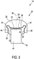
- Fig. 3 shows a schematic sectional view of the ultrasound probe 14 comprising the acoustical lens 20 and an ultrasound transducer which is generally denoted by 40.
- the ultrasound transducer 40 comprises an ultrasound transducer element 42 or an ultrasound transducer array 42 for transmitting and/or receiving ultrasound waves.
- the ultrasound transducer element 42 or the ultrasound transducer array 42 is formed as a ceramic micromachined ultrasound transducer on wafer level and attached to a support portion 44, which is provided for mechanically supporting the transducer element or array 42 and for electrically connecting the transducer elements 42.
- the support portion 44 may be a flexible mount structure having an underfill for the transducer element 42 or the transducer array 42.
- the transducer element 42 or the transducer array 42 comprises an emission surface 46 for emitting and/or receiving the ultrasound waves.
- the ultrasound transducer 40 is disposed at least partially within the cavity 32 and attached to the inner surfaces 26, 30 of the cavity 32 by means of a connection mold or a glue 48.
- the glue 48 is formed as a PDMS (Polydimethylsiloxan) or a Polybutadine in order to fix the ultrasound transducer 40 in the cavity 32 and to form a good acoustic connection to the inner surface 26.
- the ultrasound transducer 40 is disposed within the cavity 32 so that the emission surface 46 faces the inner surface 26 and the side walls 28 support the ultrasound transducer 40 laterally. In this position, the ultrasound waves emitted from the emission surface 46 can be provided to the inner surface 26 and further submitted to the outer surface 24 via the main body 22. Due to the convexly curved shape of the inner surface 26, a central portion of the emission surface 46, which forms the main emission direction of the ultrasound transducer element 42 or the transducer array 42 along the axis of symmetry 36, is in close contact to the inner surface 26 so that the attenuation and the reflections at this central portion are reduced.
- an ultrasound transducer 40 is pressed into the cavity 32, so that the glue 48 is driven from the central portion of the emission surface 46 to the peripheral portion and also avoids or air bubbles included in the mold 48 are driven to the peripheral portion as described in the following.
- the moisture barrier layer 38 protects the glue 32, which is hydrophilic, from the outside, so that the ultrasound probe 14 can be used in wet environments without damaging the glue 48 by intruding moisture.
- the recesses 34 serve as a cavity for excessive glue 48, which is pressed during the manufacturing process to the sides into the recesses 34 so that the emission surface 46 can be brought into close contact to the inner surface 26.
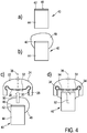
- Figs. 4a-d show process steps to manufacture the ultrasound probe 14 including the acoustical lens 20 and the ultrasound transducer 40.
- fig. 4a-d show process steps to connect the ultrasound transducer 40 into the cavity 32 of the acoustical lens 20.
- the ultrasound transducer 40 comprises the transducer element 42 or the transducer array 42 attached to the support portion 44 and having the emission surface 46 as described above.
- the transducer elements 42 can be the capacitive micromachined ultrasound transducers (CMUTs) manufactured by the available microfabrication techniques, such as sacrificial layer etching or wafer-bonding.
- CMUTs capacitive micromachined ultrasound transducers
- the transducer elements 42 can be also piezoelectric based ultrasound transducers (PZTs).
- the upper portion of the support portion 40 including the transducer element 42 or the transducer array 42 is coated with the glue 48 by means of dip-coating or spray-coating as shown in fig. 4b .
- the ultrasound transducer 40 and the attached glue 48 are introduced into the cavity 32 as indicated by an arrow 50.
- the ultrasound transducer 40 is introduced into the cavity 32 so that the emission surface 46 faces the inner surface 26 and that the ultrasound transducer 40 is introduced coaxially to the axis of symmetry 36 into the cavity 32.
- the ultrasound transducer 40 is pressed into the cavity 32 as shown in fig. 4d by an arrow 52.
- the glue 48 disposed between the emission surface 46 and the inner surface 26 is moved or driven to the peripheral parts of the emission surface 46 and into the recesses 34 as shown by arrows 54.
Landscapes
- Health & Medical Sciences (AREA)
- Life Sciences & Earth Sciences (AREA)
- Physics & Mathematics (AREA)
- Pathology (AREA)
- Engineering & Computer Science (AREA)
- General Health & Medical Sciences (AREA)
- Medical Informatics (AREA)
- Veterinary Medicine (AREA)
- Biophysics (AREA)
- Radiology & Medical Imaging (AREA)
- Biomedical Technology (AREA)
- Heart & Thoracic Surgery (AREA)
- Nuclear Medicine, Radiotherapy & Molecular Imaging (AREA)
- Molecular Biology (AREA)
- Surgery (AREA)
- Animal Behavior & Ethology (AREA)
- Public Health (AREA)
- Acoustics & Sound (AREA)
- Multimedia (AREA)
- Chemical & Material Sciences (AREA)
- Analytical Chemistry (AREA)
- Biochemistry (AREA)
- General Physics & Mathematics (AREA)
- Immunology (AREA)
- Gynecology & Obstetrics (AREA)
- Ultra Sonic Daignosis Equipment (AREA)
- Transducers For Ultrasonic Waves (AREA)
Claims (11)
- Lentille acoustique (20) pour une sonde ultrasonore (14) comprenant :- une surface interne (26) pour faire face à une surface d'émission (46) d'un transducteur ultrasonore (40) et pour recevoir des ondes ultrasonores du transducteur ultrasonore,- une surface externe (24) pour émettre les ondes ultrasonores reçues sur la surface interne,dans laquelle la surface interne est conformée en surface à courbure convexe, et
caractérisée en ce que :au moins un évidement (34) est associé à un bord de la surface interne pour capturer un matériau de moulage etdans laquelle les parois latérales (28) sont associées à la surface interne en formant une cavité conjointement avec la surface interne pour recevoir le transducteur ultrasonore, etdans lequel l'évidement est formé entre les parois latérales et la surface interne. - Lentille acoustique selon la revendication 1, dans laquelle la surface interne est conformée en partie unique à courbure convexe.
- Lentille acoustique selon la revendication 1, dans laquelle l'évidement à une forme concave.
- Lentille acoustique selon la revendication 1, dans laquelle l'évidement est conformé en encoche entourant la surface interne au moins en partie.
- Lentille acoustique selon la revendication 1, dans laquelle l'évidement est conformé en encoche séparant la surface interne des surfaces internes (30) des parois latérales.
- Lentille acoustique selon la revendication 1, dans laquelle la surface interne est recouverte d'un revêtement (38) formant une barrière à l'humidité.
- Lentille acoustique selon la revendication 6, dans laquelle les surfaces internes des parois latérales et une surface de l'évidement sont recouvertes par le revêtement formant la barrière à l'humidité.
- Lentille acoustique selon la revendication 6, dans laquelle le revêtement est conformé en couche métallique.
- Sonde de transducteur ultrasonore (14) comprenant :- un transducteur ultrasonore (40) comprenant une surface d'émission (46) pour émettre des ondes ultrasonores et- la lentille acoustique de la revendication 1 ayant la surface interne (26) faisant face à la surface d'émission du transducteur ultrasonore pour recevoir les ondes ultrasonores de la surface d'émission et la surface externe (24) pour émettre les ondes ultrasonores reçues sur la surface interne, dans laquelle les parois latérales (28) sont associées à la surface interne en formant une cavité conjointement avec la surface interne pour recevoir le transducteur ultrasonore.
- Sonde de transducteur ultrasonore selon la revendication 9, dans laquelle la surface d'émission est raccordée à la surface interne au moyen d'un moule de liaison (48).
- Sonde de transducteur ultrasonore selon la revendication 9, dans laquelle la surface d'émission est une surface planaire.
Applications Claiming Priority (2)
| Application Number | Priority Date | Filing Date | Title |
|---|---|---|---|
| EP14168372 | 2014-05-14 | ||
| PCT/EP2015/059439 WO2015173027A1 (fr) | 2014-05-14 | 2015-04-30 | Lentille acoustique et sonde à transducteur à ultrasons |
Publications (2)
| Publication Number | Publication Date |
|---|---|
| EP3143612A1 EP3143612A1 (fr) | 2017-03-22 |
| EP3143612B1 true EP3143612B1 (fr) | 2019-09-11 |
Family
ID=50693553
Family Applications (1)
| Application Number | Title | Priority Date | Filing Date |
|---|---|---|---|
| EP15718923.4A Active EP3143612B1 (fr) | 2014-05-14 | 2015-04-30 | Lentille acoustique et sonde de transducteur ultrasonore |
Country Status (5)
| Country | Link |
|---|---|
| US (1) | US10923099B2 (fr) |
| EP (1) | EP3143612B1 (fr) |
| JP (1) | JP6588467B2 (fr) |
| CN (1) | CN106659463B (fr) |
| WO (1) | WO2015173027A1 (fr) |
Families Citing this family (10)
| Publication number | Priority date | Publication date | Assignee | Title |
|---|---|---|---|---|
| DE102015216200A1 (de) * | 2015-08-25 | 2017-03-02 | Robert Bosch Gmbh | Akustischer Sensor mit einem Gehäuse und einem an diesem Gehäuse angeordneten Membranelement |
| CN107666731B (zh) * | 2017-08-23 | 2020-06-19 | 安徽工程大学 | 一种纳米电子材料制备用的超声磁热装置 |
| JP7192640B2 (ja) * | 2019-04-23 | 2022-12-20 | 株式会社Soken | 超音波センサ |
| US20210085415A1 (en) * | 2019-09-23 | 2021-03-25 | GE Precision Healthcare LLC | Methods and systems for an accessory holder |
| WO2021101429A1 (fr) * | 2019-11-19 | 2021-05-27 | Fingerprint Cards Ab | Dispositif d'imagerie biométrique ultrasonore avec réduction de la réflexion |
| JP7680877B2 (ja) * | 2021-05-06 | 2025-05-21 | 富士フイルム株式会社 | 音響カプラ、超音波画像処理方法、及び超音波撮像装置 |
| US12285636B2 (en) | 2021-08-05 | 2025-04-29 | The University Of Washington | Non-planar holographic beam shaping lenses for acoustics |
| CN114271855B (zh) * | 2021-12-24 | 2025-11-25 | 深圳市影越医疗科技有限公司 | 一种超声检测探头 |
| CN114098821B (zh) * | 2021-12-24 | 2025-04-25 | 深圳市影越医疗科技有限公司 | 一种超声探头 |
| DE102022210443A1 (de) * | 2022-09-30 | 2024-04-04 | Richard Wolf Gmbh | Vorrichtung zur Applikation von Schallwellen |
Family Cites Families (21)
| Publication number | Priority date | Publication date | Assignee | Title |
|---|---|---|---|---|
| JPS59225044A (ja) * | 1983-06-07 | 1984-12-18 | 松下電器産業株式会社 | 超音波トランスジユ−サ |
| JPS61118094A (ja) * | 1984-11-14 | 1986-06-05 | Matsushita Electric Ind Co Ltd | 超音波診断装置用探触子 |
| US4659956A (en) | 1985-01-24 | 1987-04-21 | General Electric Company | Compound focus ultrasonic transducer |
| US5465724A (en) * | 1993-05-28 | 1995-11-14 | Acuson Corporation | Compact rotationally steerable ultrasound transducer |
| JPH07150114A (ja) * | 1993-11-26 | 1995-06-13 | Olympus Optical Co Ltd | レンズ接合装置 |
| JPH08612A (ja) * | 1994-06-21 | 1996-01-09 | Toshiba Medical Eng Co Ltd | 超音波プローブ |
| US5562096A (en) * | 1994-06-28 | 1996-10-08 | Acuson Corporation | Ultrasonic transducer probe with axisymmetric lens |
| JPH0975345A (ja) | 1995-09-12 | 1997-03-25 | Fuji Photo Optical Co Ltd | 超音波検査装置 |
| US5976091A (en) | 1998-06-08 | 1999-11-02 | Acuson Corporation | Limited diffraction broadband phased array transducer with frequency controlled two dimensional aperture capability |
| US6940659B2 (en) * | 2002-01-11 | 2005-09-06 | Ultradent Products, Inc. | Cone-shaped lens having increased forward light intensity and kits incorporating such lenses |
| JP2004105741A (ja) | 2003-09-26 | 2004-04-08 | Olympus Corp | 超音波探触子 |
| EP1542005B1 (fr) * | 2003-12-09 | 2007-01-24 | Kabushiki Kaisha Toshiba | Sonde ultrasonore avec une couche d'adaptation acoustique conductrice |
| JP5241091B2 (ja) * | 2006-10-13 | 2013-07-17 | 日本電波工業株式会社 | 超音波探触子 |
| US7888847B2 (en) | 2006-10-24 | 2011-02-15 | Dennis Raymond Dietz | Apodizing ultrasonic lens |
| JP4933392B2 (ja) * | 2007-04-02 | 2012-05-16 | 富士フイルム株式会社 | 超音波探触子及びその製造方法 |
| CN102026581A (zh) * | 2008-05-15 | 2011-04-20 | 株式会社日立医疗器械 | 超声波探头及其制造方法和超声波诊断装置 |
| US8506490B2 (en) * | 2008-05-30 | 2013-08-13 | W.L. Gore & Associates, Inc. | Real time ultrasound probe |
| US8316518B2 (en) | 2008-09-18 | 2012-11-27 | Visualsonics Inc. | Methods for manufacturing ultrasound transducers and other components |
| EP2308397A1 (fr) | 2009-10-07 | 2011-04-13 | Dornier MedTech Systems GmbH | Tête d'applicateur pour émettre des ondes de choc |
| CN103827960B (zh) | 2011-09-26 | 2017-12-08 | 皇家飞利浦有限公司 | 具有声透镜的超声探头 |
| WO2015177631A2 (fr) * | 2014-05-20 | 2015-11-26 | Cgg Services Sa | Procédés et systèmes pour une source sismique de fond océanique |
-
2015
- 2015-04-30 WO PCT/EP2015/059439 patent/WO2015173027A1/fr not_active Ceased
- 2015-04-30 EP EP15718923.4A patent/EP3143612B1/fr active Active
- 2015-04-30 CN CN201580025193.9A patent/CN106659463B/zh active Active
- 2015-04-30 US US15/309,493 patent/US10923099B2/en active Active
- 2015-04-30 JP JP2016567192A patent/JP6588467B2/ja active Active
Non-Patent Citations (1)
| Title |
|---|
| None * |
Also Published As
| Publication number | Publication date |
|---|---|
| JP6588467B2 (ja) | 2019-10-09 |
| US10923099B2 (en) | 2021-02-16 |
| JP2017518797A (ja) | 2017-07-13 |
| US20170154619A1 (en) | 2017-06-01 |
| CN106659463A (zh) | 2017-05-10 |
| CN106659463B (zh) | 2019-11-19 |
| EP3143612A1 (fr) | 2017-03-22 |
| WO2015173027A1 (fr) | 2015-11-19 |
Similar Documents
| Publication | Publication Date | Title |
|---|---|---|
| US10923099B2 (en) | Acoustical lens and ultrasound transducer probe | |
| CN103720486B (zh) | 超声波转换器装置、探测头、超声波探测器及电子设备 | |
| CN103181785B (zh) | 超声波探头及其制造方法 | |
| JP5954773B2 (ja) | 超音波プローブおよび超音波プローブの製造方法 | |
| CN105848792B (zh) | 具有可变厚度解匹配层的超声换能器和超声成像系统 | |
| US9089875B2 (en) | Ultrasound backing element, transducer and ultrasound probe including the same | |
| US20130241356A1 (en) | Probe for ultrasonic diagnostic apparatus | |
| EP2266712B1 (fr) | Transducteur pour dispositif de diagnostic ultrasonique et son procédé de fabrication | |
| US20150115773A1 (en) | Ultrasound transducer and method for manufacturing an ultrasound transducer | |
| US20160144402A1 (en) | Capacitive transducer and sample information acquisition apparatus | |
| US20180214126A1 (en) | Capacitive micromachined ultrasonic transducer, probe and method of manufacturing the same | |
| CN104665871B (zh) | 超声波装置、探测器、电子设备以及超声波图像装置 | |
| JP7856323B2 (ja) | 超音波プローブヘッド、超音波プローブ、及び超音波診断装置 | |
| CN106923861B (zh) | 压电元件、探测器以及超声波测定装置 | |
| KR101484959B1 (ko) | 초음파 트랜스듀서, 이를 포함한 초음파 프로브 및 초음파 진단 장치 | |
| KR20110003057A (ko) | 초음파 프로브 및 초음파 진단장치 | |
| US11911114B2 (en) | Ultrasonic probe and ultrasonic imaging apparatus including the same | |
| JP6200246B2 (ja) | 探触子 | |
| US12310791B2 (en) | Ultrasound probe and ultrasound diagnostic apparatus | |
| JP7816794B2 (ja) | 可撓性超音波プローブヘッド、超音波プローブ、及び超音波診断装置 | |
| CN117426790A (zh) | 超声波探头及超声波诊断装置 | |
| KR20180068586A (ko) | 초음파 진단 장치용 프로브 | |
| KR20170131923A (ko) | 고주파형 초음파 센서 | |
| KR20150084635A (ko) | 초음파 프로브 및 그 제조 방법 | |
| JP2010219634A (ja) | 超音波探触子、および超音波診断装置 |
Legal Events
| Date | Code | Title | Description |
|---|---|---|---|
| STAA | Information on the status of an ep patent application or granted ep patent |
Free format text: STATUS: THE INTERNATIONAL PUBLICATION HAS BEEN MADE |
|
| PUAI | Public reference made under article 153(3) epc to a published international application that has entered the european phase |
Free format text: ORIGINAL CODE: 0009012 |
|
| STAA | Information on the status of an ep patent application or granted ep patent |
Free format text: STATUS: REQUEST FOR EXAMINATION WAS MADE |
|
| 17P | Request for examination filed |
Effective date: 20161214 |
|
| AK | Designated contracting states |
Kind code of ref document: A1 Designated state(s): AL AT BE BG CH CY CZ DE DK EE ES FI FR GB GR HR HU IE IS IT LI LT LU LV MC MK MT NL NO PL PT RO RS SE SI SK SM TR |
|
| AX | Request for extension of the european patent |
Extension state: BA ME |
|
| DAV | Request for validation of the european patent (deleted) | ||
| DAX | Request for extension of the european patent (deleted) | ||
| RIC1 | Information provided on ipc code assigned before grant |
Ipc: G01N 29/24 20060101ALI20190213BHEP Ipc: A61B 8/00 20060101ALI20190213BHEP Ipc: G10K 11/30 20060101AFI20190213BHEP |
|
| GRAP | Despatch of communication of intention to grant a patent |
Free format text: ORIGINAL CODE: EPIDOSNIGR1 |
|
| STAA | Information on the status of an ep patent application or granted ep patent |
Free format text: STATUS: GRANT OF PATENT IS INTENDED |
|
| INTG | Intention to grant announced |
Effective date: 20190401 |
|
| GRAS | Grant fee paid |
Free format text: ORIGINAL CODE: EPIDOSNIGR3 |
|
| GRAA | (expected) grant |
Free format text: ORIGINAL CODE: 0009210 |
|
| STAA | Information on the status of an ep patent application or granted ep patent |
Free format text: STATUS: THE PATENT HAS BEEN GRANTED |
|
| AK | Designated contracting states |
Kind code of ref document: B1 Designated state(s): AL AT BE BG CH CY CZ DE DK EE ES FI FR GB GR HR HU IE IS IT LI LT LU LV MC MK MT NL NO PL PT RO RS SE SI SK SM TR |
|
| REG | Reference to a national code |
Ref country code: GB Ref legal event code: FG4D |
|
| REG | Reference to a national code |
Ref country code: CH Ref legal event code: EP |
|
| REG | Reference to a national code |
Ref country code: AT Ref legal event code: REF Ref document number: 1179495 Country of ref document: AT Kind code of ref document: T Effective date: 20190915 |
|
| REG | Reference to a national code |
Ref country code: DE Ref legal event code: R096 Ref document number: 602015037728 Country of ref document: DE Ref country code: IE Ref legal event code: FG4D |
|
| REG | Reference to a national code |
Ref country code: DE Ref legal event code: R084 Ref document number: 602015037728 Country of ref document: DE |
|
| REG | Reference to a national code |
Ref country code: GB Ref legal event code: 746 Effective date: 20191104 |
|
| REG | Reference to a national code |
Ref country code: NL Ref legal event code: MP Effective date: 20190911 |
|
| REG | Reference to a national code |
Ref country code: LT Ref legal event code: MG4D |
|
| PG25 | Lapsed in a contracting state [announced via postgrant information from national office to epo] |
Ref country code: FI Free format text: LAPSE BECAUSE OF FAILURE TO SUBMIT A TRANSLATION OF THE DESCRIPTION OR TO PAY THE FEE WITHIN THE PRESCRIBED TIME-LIMIT Effective date: 20190911 Ref country code: NO Free format text: LAPSE BECAUSE OF FAILURE TO SUBMIT A TRANSLATION OF THE DESCRIPTION OR TO PAY THE FEE WITHIN THE PRESCRIBED TIME-LIMIT Effective date: 20191211 Ref country code: BG Free format text: LAPSE BECAUSE OF FAILURE TO SUBMIT A TRANSLATION OF THE DESCRIPTION OR TO PAY THE FEE WITHIN THE PRESCRIBED TIME-LIMIT Effective date: 20191211 Ref country code: SE Free format text: LAPSE BECAUSE OF FAILURE TO SUBMIT A TRANSLATION OF THE DESCRIPTION OR TO PAY THE FEE WITHIN THE PRESCRIBED TIME-LIMIT Effective date: 20190911 Ref country code: HR Free format text: LAPSE BECAUSE OF FAILURE TO SUBMIT A TRANSLATION OF THE DESCRIPTION OR TO PAY THE FEE WITHIN THE PRESCRIBED TIME-LIMIT Effective date: 20190911 Ref country code: LT Free format text: LAPSE BECAUSE OF FAILURE TO SUBMIT A TRANSLATION OF THE DESCRIPTION OR TO PAY THE FEE WITHIN THE PRESCRIBED TIME-LIMIT Effective date: 20190911 |
|
| PG25 | Lapsed in a contracting state [announced via postgrant information from national office to epo] |
Ref country code: LV Free format text: LAPSE BECAUSE OF FAILURE TO SUBMIT A TRANSLATION OF THE DESCRIPTION OR TO PAY THE FEE WITHIN THE PRESCRIBED TIME-LIMIT Effective date: 20190911 Ref country code: GR Free format text: LAPSE BECAUSE OF FAILURE TO SUBMIT A TRANSLATION OF THE DESCRIPTION OR TO PAY THE FEE WITHIN THE PRESCRIBED TIME-LIMIT Effective date: 20191212 Ref country code: RS Free format text: LAPSE BECAUSE OF FAILURE TO SUBMIT A TRANSLATION OF THE DESCRIPTION OR TO PAY THE FEE WITHIN THE PRESCRIBED TIME-LIMIT Effective date: 20190911 Ref country code: AL Free format text: LAPSE BECAUSE OF FAILURE TO SUBMIT A TRANSLATION OF THE DESCRIPTION OR TO PAY THE FEE WITHIN THE PRESCRIBED TIME-LIMIT Effective date: 20190911 Ref country code: ES Free format text: LAPSE BECAUSE OF FAILURE TO SUBMIT A TRANSLATION OF THE DESCRIPTION OR TO PAY THE FEE WITHIN THE PRESCRIBED TIME-LIMIT Effective date: 20190911 |
|
| RAP2 | Party data changed (patent owner data changed or rights of a patent transferred) |
Owner name: KONINKLIJKE PHILIPS N.V. |
|
| REG | Reference to a national code |
Ref country code: AT Ref legal event code: MK05 Ref document number: 1179495 Country of ref document: AT Kind code of ref document: T Effective date: 20190911 |
|
| PG25 | Lapsed in a contracting state [announced via postgrant information from national office to epo] |
Ref country code: PL Free format text: LAPSE BECAUSE OF FAILURE TO SUBMIT A TRANSLATION OF THE DESCRIPTION OR TO PAY THE FEE WITHIN THE PRESCRIBED TIME-LIMIT Effective date: 20190911 Ref country code: EE Free format text: LAPSE BECAUSE OF FAILURE TO SUBMIT A TRANSLATION OF THE DESCRIPTION OR TO PAY THE FEE WITHIN THE PRESCRIBED TIME-LIMIT Effective date: 20190911 Ref country code: NL Free format text: LAPSE BECAUSE OF FAILURE TO SUBMIT A TRANSLATION OF THE DESCRIPTION OR TO PAY THE FEE WITHIN THE PRESCRIBED TIME-LIMIT Effective date: 20190911 Ref country code: PT Free format text: LAPSE BECAUSE OF FAILURE TO SUBMIT A TRANSLATION OF THE DESCRIPTION OR TO PAY THE FEE WITHIN THE PRESCRIBED TIME-LIMIT Effective date: 20200113 Ref country code: RO Free format text: LAPSE BECAUSE OF FAILURE TO SUBMIT A TRANSLATION OF THE DESCRIPTION OR TO PAY THE FEE WITHIN THE PRESCRIBED TIME-LIMIT Effective date: 20190911 Ref country code: IT Free format text: LAPSE BECAUSE OF FAILURE TO SUBMIT A TRANSLATION OF THE DESCRIPTION OR TO PAY THE FEE WITHIN THE PRESCRIBED TIME-LIMIT Effective date: 20190911 Ref country code: AT Free format text: LAPSE BECAUSE OF FAILURE TO SUBMIT A TRANSLATION OF THE DESCRIPTION OR TO PAY THE FEE WITHIN THE PRESCRIBED TIME-LIMIT Effective date: 20190911 |
|
| PG25 | Lapsed in a contracting state [announced via postgrant information from national office to epo] |
Ref country code: SM Free format text: LAPSE BECAUSE OF FAILURE TO SUBMIT A TRANSLATION OF THE DESCRIPTION OR TO PAY THE FEE WITHIN THE PRESCRIBED TIME-LIMIT Effective date: 20190911 Ref country code: CZ Free format text: LAPSE BECAUSE OF FAILURE TO SUBMIT A TRANSLATION OF THE DESCRIPTION OR TO PAY THE FEE WITHIN THE PRESCRIBED TIME-LIMIT Effective date: 20190911 Ref country code: SK Free format text: LAPSE BECAUSE OF FAILURE TO SUBMIT A TRANSLATION OF THE DESCRIPTION OR TO PAY THE FEE WITHIN THE PRESCRIBED TIME-LIMIT Effective date: 20190911 Ref country code: IS Free format text: LAPSE BECAUSE OF FAILURE TO SUBMIT A TRANSLATION OF THE DESCRIPTION OR TO PAY THE FEE WITHIN THE PRESCRIBED TIME-LIMIT Effective date: 20200224 |
|
| REG | Reference to a national code |
Ref country code: DE Ref legal event code: R097 Ref document number: 602015037728 Country of ref document: DE |
|
| PLBE | No opposition filed within time limit |
Free format text: ORIGINAL CODE: 0009261 |
|
| STAA | Information on the status of an ep patent application or granted ep patent |
Free format text: STATUS: NO OPPOSITION FILED WITHIN TIME LIMIT |
|
| PG2D | Information on lapse in contracting state deleted |
Ref country code: IS |
|
| PG25 | Lapsed in a contracting state [announced via postgrant information from national office to epo] |
Ref country code: DK Free format text: LAPSE BECAUSE OF FAILURE TO SUBMIT A TRANSLATION OF THE DESCRIPTION OR TO PAY THE FEE WITHIN THE PRESCRIBED TIME-LIMIT Effective date: 20190911 Ref country code: IS Free format text: LAPSE BECAUSE OF FAILURE TO SUBMIT A TRANSLATION OF THE DESCRIPTION OR TO PAY THE FEE WITHIN THE PRESCRIBED TIME-LIMIT Effective date: 20200112 |
|
| 26N | No opposition filed |
Effective date: 20200615 |
|
| PG25 | Lapsed in a contracting state [announced via postgrant information from national office to epo] |
Ref country code: SI Free format text: LAPSE BECAUSE OF FAILURE TO SUBMIT A TRANSLATION OF THE DESCRIPTION OR TO PAY THE FEE WITHIN THE PRESCRIBED TIME-LIMIT Effective date: 20190911 |
|
| PG25 | Lapsed in a contracting state [announced via postgrant information from national office to epo] |
Ref country code: MC Free format text: LAPSE BECAUSE OF FAILURE TO SUBMIT A TRANSLATION OF THE DESCRIPTION OR TO PAY THE FEE WITHIN THE PRESCRIBED TIME-LIMIT Effective date: 20190911 |
|
| REG | Reference to a national code |
Ref country code: CH Ref legal event code: PL |
|
| PG25 | Lapsed in a contracting state [announced via postgrant information from national office to epo] |
Ref country code: LI Free format text: LAPSE BECAUSE OF NON-PAYMENT OF DUE FEES Effective date: 20200430 Ref country code: CH Free format text: LAPSE BECAUSE OF NON-PAYMENT OF DUE FEES Effective date: 20200430 Ref country code: FR Free format text: LAPSE BECAUSE OF NON-PAYMENT OF DUE FEES Effective date: 20200430 Ref country code: LU Free format text: LAPSE BECAUSE OF NON-PAYMENT OF DUE FEES Effective date: 20200430 |
|
| REG | Reference to a national code |
Ref country code: BE Ref legal event code: MM Effective date: 20200430 |
|
| PG25 | Lapsed in a contracting state [announced via postgrant information from national office to epo] |
Ref country code: BE Free format text: LAPSE BECAUSE OF NON-PAYMENT OF DUE FEES Effective date: 20200430 |
|
| PG25 | Lapsed in a contracting state [announced via postgrant information from national office to epo] |
Ref country code: IE Free format text: LAPSE BECAUSE OF NON-PAYMENT OF DUE FEES Effective date: 20200430 |
|
| PG25 | Lapsed in a contracting state [announced via postgrant information from national office to epo] |
Ref country code: TR Free format text: LAPSE BECAUSE OF FAILURE TO SUBMIT A TRANSLATION OF THE DESCRIPTION OR TO PAY THE FEE WITHIN THE PRESCRIBED TIME-LIMIT Effective date: 20190911 Ref country code: MT Free format text: LAPSE BECAUSE OF FAILURE TO SUBMIT A TRANSLATION OF THE DESCRIPTION OR TO PAY THE FEE WITHIN THE PRESCRIBED TIME-LIMIT Effective date: 20190911 Ref country code: CY Free format text: LAPSE BECAUSE OF FAILURE TO SUBMIT A TRANSLATION OF THE DESCRIPTION OR TO PAY THE FEE WITHIN THE PRESCRIBED TIME-LIMIT Effective date: 20190911 |
|
| PG25 | Lapsed in a contracting state [announced via postgrant information from national office to epo] |
Ref country code: MK Free format text: LAPSE BECAUSE OF FAILURE TO SUBMIT A TRANSLATION OF THE DESCRIPTION OR TO PAY THE FEE WITHIN THE PRESCRIBED TIME-LIMIT Effective date: 20190911 |
|
| PGFP | Annual fee paid to national office [announced via postgrant information from national office to epo] |
Ref country code: DE Payment date: 20250429 Year of fee payment: 11 |
|
| PGFP | Annual fee paid to national office [announced via postgrant information from national office to epo] |
Ref country code: GB Payment date: 20250428 Year of fee payment: 11 |