EP3143690B1 - Linearantriebskraftabgleich mittels back-emf - Google Patents
Linearantriebskraftabgleich mittels back-emf Download PDFInfo
- Publication number
- EP3143690B1 EP3143690B1 EP15714709.1A EP15714709A EP3143690B1 EP 3143690 B1 EP3143690 B1 EP 3143690B1 EP 15714709 A EP15714709 A EP 15714709A EP 3143690 B1 EP3143690 B1 EP 3143690B1
- Authority
- EP
- European Patent Office
- Prior art keywords
- actuators
- bemf
- during
- controller
- mode
- Prior art date
- Legal status (The legal status is an assumption and is not a legal conclusion. Google has not performed a legal analysis and makes no representation as to the accuracy of the status listed.)
- Active
Links
Images



Classifications
-
- H—ELECTRICITY
- H02—GENERATION; CONVERSION OR DISTRIBUTION OF ELECTRIC POWER
- H02P—CONTROL OR REGULATION OF ELECTRIC MOTORS, ELECTRIC GENERATORS OR DYNAMO-ELECTRIC CONVERTERS; CONTROLLING TRANSFORMERS, REACTORS OR CHOKE COILS
- H02P6/00—Arrangements for controlling synchronous motors or other dynamo-electric motors using electronic commutation dependent on the rotor position; Electronic commutators therefor
- H02P6/04—Arrangements for controlling or regulating the speed or torque of more than one motor
-
- H—ELECTRICITY
- H02—GENERATION; CONVERSION OR DISTRIBUTION OF ELECTRIC POWER
- H02P—CONTROL OR REGULATION OF ELECTRIC MOTORS, ELECTRIC GENERATORS OR DYNAMO-ELECTRIC CONVERTERS; CONTROLLING TRANSFORMERS, REACTORS OR CHOKE COILS
- H02P25/00—Arrangements or methods for the control of AC motors characterised by the kind of AC motor or by structural details
- H02P25/02—Arrangements or methods for the control of AC motors characterised by the kind of AC motor or by structural details characterised by the kind of motor
- H02P25/06—Linear motors
Definitions
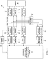
- FIGURE 1 through 6 described below, and the various embodiments used to describe the principles of the present invention in this patent document are by way of illustration only and should not be construed in any way to limit the scope of the invention. Those skilled in the art will understand that the principles of the present invention may be implemented in any type of suitably arranged device or system.
- Current sensors 28 are coupled to each full bridge drive 20 and output to the controller 12 feedback signals indicative of the actuator currents provided by the respective full bridge drives 20.
- Each current sensor 28 feeds a current drive feedback signal to a feedback control loop (shown in FIGURE 4 ) within the controller 12, such as by using a multiplexer to select the actuator current to be sampled by the controller 12.
- the controller 12 may adjust the PWM drive signal provided to the gate drivers 18, based on the current drive feedback signal, to create the desired drive currents for the actuators 14 in order to control a desired position of the controllable member 16.
- the position of the controllable member 16 could be defined based on a position input (not shown).
- the controller 12 can use the V bemf voltage values from the conversion module 26 to adjust the currents provided to the actuators 14, which can help to reduce or prevent unmatched actuator forces that could distort the controllable member 16.
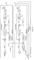
- FIGURE 4 illustrates a block diagram of each example feedback control loop 29 associated with each actuator 14 according to this disclosure.
- each control loop 29 includes a respective PWM signal generated by the controller 12, a gate driver 18, a full bridge drive 20, an actuator 14, and the combination of the voltage buffer 22, multiplexer 24, and conversion module 26.
- the reference voltage V bemf generated by the first actuator 14 is passed by the first control loop 29 to the control loops 29 of the other actuators 14 and is used as a reference.
- the loop control functions are handled via the controller 12.
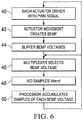
- Each of the actuator 14 loop control functions are measured during retrace independently by the controller 12.
- FIGURE 5 illustrates an example of sample parameters for an actuator 14 according to this disclosure.
- FIGURE 5 illustrates the unit conversions for a sample of one actuator 14.
- the conversions document the units of torque and speed in reference to revolution/minute/volt that represents the V bemf constant and corresponding force/amperes. These conversions are used as samples to understand the V bemf constant used on actuators 14.
Landscapes
- Engineering & Computer Science (AREA)
- Power Engineering (AREA)
- Control Of Linear Motors (AREA)
- Control Of Motors That Do Not Use Commutators (AREA)
- Mechanical Optical Scanning Systems (AREA)
Claims (15)
- Vorrichtung, Folgendes umfassend:
eine Steuerung (12), die konfiguriert ist, um:eine Vielzahl von Aktuatoren (14) zu steuern, die Kräfte für ein betätigbares Element (16) bereitstellen;einen Parameter jedes der Aktuatoren (14) während eines Rückverfolgungsmodus des Elements (16), das von einer zweiten Position zu einer ersten Position zurückkehrt, zu identifizieren; unddaraufhin Steuersignale bereitzustellen, um die Aktuatoren (14) während eines Betätigungsmodus anzutreiben, in dem das Element (16) zwischen der ersten Position und der zweiten Position bewegt wird, so dass die von den Aktuatoren (14) an das Element (16) während des Betätigungsmodus bereitgestellten Kräfte im Wesentlichen gleich sind;wobei der Parameter eine rückwirkende elektromotorische Kraft "BEMF" von jedem der Aktuatoren (14) umfasst; undwobei die Steuerung (12) vorzugsweise konfiguriert ist um:das BEMF von einem ersten der Aktuatoren (14) als Referenz zu verwenden; unddie Steuersignale so einzustellen, dass das BEMF der verbleibenden Aktuatoren (14) im Wesentlichen dem BEMF des ersten Aktuators (14) entspricht. - System (10), Folgendes umfassend:eine Vielzahl von Aktuatoren (14), die konfiguriert sind, um Kräfte an ein betätigbares Element (16) bereitzustellen, um das Element zwischen einer ersten Position und einer zweiten Position während eines Betätigungsmodus zu betätigen, wobei die Aktuatoren (14) auch konfiguriert sind, um das Element (16) während eines Rückverfolgungsmodus von der zweiten Position in die erste Position zurückzubringen; unddie Vorrichtung nach Anspruch 1.
- System (10) nach Anspruch 2, wobei die Steuerung (12) konfiguriert ist, um den Parameter während eines mittleren Abschnitts des Rückverfolgungsmodus zu bestimmen.
- System (10) nach Anspruch 2, wobei:die Steuerung (12) konfiguriert ist, um Antriebsströme zu steuern, die den Aktuatoren (14) während des Betätigungsmodus und des Rückverfolgungsmodus bereitgestellt werden; unddie Steuerung (12) konfiguriert ist, um den Parameter während des Rückverfolgungsmodus zu bestimmen, wennden Aktuatoren (14) keine Antriebsströme bereitgestellt werden.
- System (10) nach Anspruch 2, wobei die Steuerung (12) konfiguriert ist, um die Aktuatoren (14) zu steuern, damit das Element (16) zwischen der ersten Position und der zweiten Position linear betätigt werden kann.
- System (10) nach Anspruch 5, wobei die Steuerung (12) konfiguriert ist, um die Aktuatoren (14) zu steuern, damit das Element (16) im Betätigungsmodus entlang einer einzelnen Achse betätigt werden kann.
- System (10) nach Anspruch 5, wobei:das Element (16) einen Spiegel umfasst; unddie Steuerung (12) konfiguriert ist, um den Spiegel während des Rückverfolgungsmodus zurückzuverfolgen.
- System (10) nach Anspruch 2, wobei die Steuerung (12) konfiguriert ist, um:ein Ungleichgewicht der von den Aktuatoren (14) an das Element (16) bereitgestellten Kräfte zu bestimmen; unddie Kräfte so einzustellen, dass die Kräfte im Wesentlichen ausgeglichen sind.
- Verfahren, Folgendes umfassend:das Bereitstellen von Kräften an ein betätigbares Element (16) unter Verwendung einer Vielzahl von Aktuatoren (14), um das Element (16) zwischen einer ersten Position und einer zweiten Position während eines Betätigungsmodus zu betätigen, wobei die Aktuatoren (14) das Element (16) während eines Rückführungsmodus von der zweiten Position in die erste Position zurückbringen; unddas Steuern der Aktuatoren (14) unter Verwendung einer Steuerung (12), wobei das Steuern der Aktuatoren (14) das Identifizieren eines Parameters jedes der Aktuatoren (14) während des Rückverfolgungsmodus und das antwortende Bereitstellen von Steuersignalen zum Antreiben der Aktuatoren (14) umfasst, sodass die von den Aktuatoren (14) an das Element (16) während des Betätigungsmodus bereitgestellten Kräfte im Wesentlichen gleich sind;wobei der Parameter eine rückwirkende elektromotorische Kraft "BEMF" von jedem der Aktuatoren (14) umfasst; undwobei vorzugsweise:die BEMF eines ersten Aktuators (14) als Referenz verwendet wird; unddie Steuersignale so eingestellt sind, dass das BEMF der verbleibenden Aktuatoren (14) im Wesentlichen der BEMF des ersten Aktuators (14) entspricht.
- Verfahren nach Anspruch 9, wobei der Parameter während eines mittleren Abschnitts des Rückverfolgungsmodus bestimmt wird.
- Verfahren nach Anspruch 9, ferner Folgendes umfassend:das Bereitstellen von Antriebsströmen an die Aktuatoren (14) während des Betätigungsmodus und des Rückverfolgungsmodus;wobei der Parameter während des Rückverfolgungsmodus bestimmt wird, wenn den Aktuatoren (14) keine Antriebsströme bereitgestellt werden.
- Verfahren nach Anspruch 9, wobei das Element (16) linear zwischen der ersten Position und der zweiten Position betätigt wird.
- Verfahren nach Anspruch 12, wobei das Element (16) im Betätigungsmodus entlang einer einzelnen Achse betätigt wird.
- Verfahren nach Anspruch 12, wobei:das Element (16) einen Spiegel umfasst; undder Spiegel während des Rückverfolgungsmodus zurückverfolgt wird.
- Verfahren nach Anspruch 9, ferner Folgendes umfassend:das Bestimmen eines Ungleichgewichts der Kräfte, die von den Aktuatoren an das Element bereitgestellt werden;wobei das antwortende Bereitstellen der Steuersignale die Kräfte so einstellt, dass die Kräfte im Wesentlichen ausgeglichen sind.
Applications Claiming Priority (2)
| Application Number | Priority Date | Filing Date | Title |
|---|---|---|---|
| US14/280,074 US10298164B2 (en) | 2014-05-16 | 2014-05-16 | Linear actuator force matching using back EMF |
| PCT/US2015/020756 WO2015175089A1 (en) | 2014-05-16 | 2015-03-16 | Linear actuator force matching using back emf |
Publications (2)
| Publication Number | Publication Date |
|---|---|
| EP3143690A1 EP3143690A1 (de) | 2017-03-22 |
| EP3143690B1 true EP3143690B1 (de) | 2019-10-02 |
Family
ID=52814204
Family Applications (1)
| Application Number | Title | Priority Date | Filing Date |
|---|---|---|---|
| EP15714709.1A Active EP3143690B1 (de) | 2014-05-16 | 2015-03-16 | Linearantriebskraftabgleich mittels back-emf |
Country Status (6)
| Country | Link |
|---|---|
| US (1) | US10298164B2 (de) |
| EP (1) | EP3143690B1 (de) |
| JP (1) | JP6355830B2 (de) |
| CA (1) | CA2947136C (de) |
| IL (1) | IL248622B (de) |
| WO (1) | WO2015175089A1 (de) |
Families Citing this family (2)
| Publication number | Priority date | Publication date | Assignee | Title |
|---|---|---|---|---|
| US9632491B1 (en) * | 2014-06-18 | 2017-04-25 | The United States Of America As Represented By The Administrator Of The National Aeronautics And Space Administration | Reconfigurable drive current system |
| US10422329B2 (en) | 2017-08-14 | 2019-09-24 | Raytheon Company | Push-pull compressor having ultra-high efficiency for cryocoolers or other systems |
Family Cites Families (15)
| Publication number | Priority date | Publication date | Assignee | Title |
|---|---|---|---|---|
| US4797749A (en) * | 1986-11-18 | 1989-01-10 | General Scanning, Inc. | Scanning system with tunable resonant actuator |
| JP3412877B2 (ja) | 1993-09-30 | 2003-06-03 | 株式会社リコー | 光学系移動型複写機における光学系速度制御方法 |
| US5930531A (en) * | 1995-09-12 | 1999-07-27 | Nikon Corporation | Image shifting apparatus |
| US6762745B1 (en) * | 1999-05-10 | 2004-07-13 | Immersion Corporation | Actuator control providing linear and continuous force output |
| US6686714B2 (en) * | 2002-06-21 | 2004-02-03 | International Business Machines Corporation | Method and system for improved closed loop control of sensorless brushless DC motors |
| JP4487168B2 (ja) | 2003-05-09 | 2010-06-23 | 株式会社ニコン | ステージ装置及びその駆動方法、並びに露光装置 |
| SG125151A1 (en) * | 2005-02-24 | 2006-09-29 | Seagate Technology Llc | Velocity control system for an actuator assembly |
| US7400103B2 (en) | 2005-08-08 | 2008-07-15 | Castle Creations, Inc. | Controller for a multi-phase brushless DC motor |
| JP4232834B2 (ja) * | 2007-03-07 | 2009-03-04 | セイコーエプソン株式会社 | アクチュエータ、光スキャナおよび画像形成装置 |
| US7994747B2 (en) * | 2007-07-13 | 2011-08-09 | Seagate Technology Llc | Suppressing phased motor voltage transients on disconnect |
| JP5210823B2 (ja) * | 2008-11-19 | 2013-06-12 | Hoya株式会社 | 光走査型内視鏡、光走査型内視鏡プロセッサ、および光走査型内視鏡装置 |
| WO2013126719A2 (en) | 2012-02-22 | 2013-08-29 | Magna Mirrors Of America, Inc. | Exterior rearview mirror assembly |
| DE102010063326A1 (de) * | 2010-05-25 | 2011-12-01 | Robert Bosch Gmbh | Verfahren und Vorrichtung zum Betreiben eines Stellgebers mit einem bürstenlosen Elektromotor |
| US20120229264A1 (en) * | 2011-03-09 | 2012-09-13 | Analog Devices, Inc. | Smart linear resonant actuator control |
| US8817379B2 (en) * | 2011-07-12 | 2014-08-26 | Google Inc. | Whole image scanning mirror display system |
-
2014
- 2014-05-16 US US14/280,074 patent/US10298164B2/en active Active
-
2015
- 2015-03-16 EP EP15714709.1A patent/EP3143690B1/de active Active
- 2015-03-16 WO PCT/US2015/020756 patent/WO2015175089A1/en not_active Ceased
- 2015-03-16 CA CA2947136A patent/CA2947136C/en active Active
- 2015-03-16 JP JP2017512635A patent/JP6355830B2/ja active Active
-
2016
- 2016-10-30 IL IL248622A patent/IL248622B/en active IP Right Grant
Non-Patent Citations (1)
| Title |
|---|
| None * |
Also Published As
| Publication number | Publication date |
|---|---|
| EP3143690A1 (de) | 2017-03-22 |
| US10298164B2 (en) | 2019-05-21 |
| JP6355830B2 (ja) | 2018-07-11 |
| WO2015175089A1 (en) | 2015-11-19 |
| JP2017516454A (ja) | 2017-06-15 |
| IL248622A0 (en) | 2017-01-31 |
| CA2947136C (en) | 2022-01-04 |
| IL248622B (en) | 2021-05-31 |
| US20150333684A1 (en) | 2015-11-19 |
| CA2947136A1 (en) | 2015-11-19 |
Similar Documents
| Publication | Publication Date | Title |
|---|---|---|
| US5412299A (en) | Variable servo loop compensation in an active hand controller | |
| US9018872B2 (en) | Motor control circuit | |
| US10488842B2 (en) | Device and method of motion control | |
| JP5917294B2 (ja) | モータ駆動回路 | |
| US6643606B2 (en) | Apparatus for measuring absolute rotation angle and method thereof | |
| US10700623B2 (en) | Positioning drive and method for positioning an output element | |
| EP3143690B1 (de) | Linearantriebskraftabgleich mittels back-emf | |
| JP4665507B2 (ja) | ペンレコーダ | |
| CN113746384A (zh) | 多电机同步控制装置、多电机系统和光学系统 | |
| EP0303711A1 (de) | Verfahren und gerät zum nachweis der absoluten ortung | |
| JP2002032126A (ja) | 圧電素子の位置と速度を制御する方法および装置 | |
| JP2021106456A (ja) | モータ制御装置およびモータ制御装置の制御方法 | |
| CN104901592A (zh) | 电动机控制装置 | |
| JP2001273005A (ja) | サーボ制御システム、電子機器及びゲイン調整方法 | |
| US10263545B2 (en) | Motor velocity control within an aircraft hydraulic system | |
| JP2020198727A (ja) | モータ制御装置およびモータ制御方法、光学機器 | |
| KR102098346B1 (ko) | 차량용 모터 구동 장치 | |
| JPH10271895A (ja) | モータ駆動装置 | |
| WO2012077767A1 (ja) | モータ制御回路 | |
| CN101185237A (zh) | 用于调节线性驱动装置的位置和/或速度的方法 | |
| EP0913923A2 (de) | Verfahren zum Antrieb eines Servomotors | |
| JPH08166824A (ja) | 位置固定制御装置 | |
| JP2008152523A (ja) | 位置制御装置とその制御方法 | |
| JPH0942919A (ja) | 変位計および自動ゼロ点調整方法 | |
| JP2007014126A (ja) | システム同定装置 |
Legal Events
| Date | Code | Title | Description |
|---|---|---|---|
| STAA | Information on the status of an ep patent application or granted ep patent |
Free format text: STATUS: THE INTERNATIONAL PUBLICATION HAS BEEN MADE |
|
| PUAI | Public reference made under article 153(3) epc to a published international application that has entered the european phase |
Free format text: ORIGINAL CODE: 0009012 |
|
| STAA | Information on the status of an ep patent application or granted ep patent |
Free format text: STATUS: REQUEST FOR EXAMINATION WAS MADE |
|
| 17P | Request for examination filed |
Effective date: 20161209 |
|
| AK | Designated contracting states |
Kind code of ref document: A1 Designated state(s): AL AT BE BG CH CY CZ DE DK EE ES FI FR GB GR HR HU IE IS IT LI LT LU LV MC MK MT NL NO PL PT RO RS SE SI SK SM TR |
|
| AX | Request for extension of the european patent |
Extension state: BA ME |
|
| DAV | Request for validation of the european patent (deleted) | ||
| DAX | Request for extension of the european patent (deleted) | ||
| STAA | Information on the status of an ep patent application or granted ep patent |
Free format text: STATUS: EXAMINATION IS IN PROGRESS |
|
| 17Q | First examination report despatched |
Effective date: 20181012 |
|
| GRAP | Despatch of communication of intention to grant a patent |
Free format text: ORIGINAL CODE: EPIDOSNIGR1 |
|
| STAA | Information on the status of an ep patent application or granted ep patent |
Free format text: STATUS: GRANT OF PATENT IS INTENDED |
|
| GRAJ | Information related to disapproval of communication of intention to grant by the applicant or resumption of examination proceedings by the epo deleted |
Free format text: ORIGINAL CODE: EPIDOSDIGR1 |
|
| STAA | Information on the status of an ep patent application or granted ep patent |
Free format text: STATUS: EXAMINATION IS IN PROGRESS |
|
| INTG | Intention to grant announced |
Effective date: 20190619 |
|
| RIN1 | Information on inventor provided before grant (corrected) |
Inventor name: HERRINGTON, GARY R. Inventor name: PALOMINO, STEVEN Inventor name: SIGLER, PATRICK J. Inventor name: ROBARGE, JAMES Inventor name: GOHLKE, MARK Inventor name: SAVAGE, LAWRENCE E., II |
|
| GRAP | Despatch of communication of intention to grant a patent |
Free format text: ORIGINAL CODE: EPIDOSNIGR1 |
|
| STAA | Information on the status of an ep patent application or granted ep patent |
Free format text: STATUS: GRANT OF PATENT IS INTENDED |
|
| INTC | Intention to grant announced (deleted) | ||
| GRAS | Grant fee paid |
Free format text: ORIGINAL CODE: EPIDOSNIGR3 |
|
| INTG | Intention to grant announced |
Effective date: 20190726 |
|
| GRAA | (expected) grant |
Free format text: ORIGINAL CODE: 0009210 |
|
| STAA | Information on the status of an ep patent application or granted ep patent |
Free format text: STATUS: THE PATENT HAS BEEN GRANTED |
|
| AK | Designated contracting states |
Kind code of ref document: B1 Designated state(s): AL AT BE BG CH CY CZ DE DK EE ES FI FR GB GR HR HU IE IS IT LI LT LU LV MC MK MT NL NO PL PT RO RS SE SI SK SM TR |
|
| REG | Reference to a national code |
Ref country code: GB Ref legal event code: FG4D |
|
| REG | Reference to a national code |
Ref country code: CH Ref legal event code: EP Ref country code: AT Ref legal event code: REF Ref document number: 1187323 Country of ref document: AT Kind code of ref document: T Effective date: 20191015 |
|
| REG | Reference to a national code |
Ref country code: DE Ref legal event code: R096 Ref document number: 602015039015 Country of ref document: DE |
|
| REG | Reference to a national code |
Ref country code: IE Ref legal event code: FG4D |
|
| REG | Reference to a national code |
Ref country code: NL Ref legal event code: MP Effective date: 20191002 |
|
| REG | Reference to a national code |
Ref country code: LT Ref legal event code: MG4D |
|
| REG | Reference to a national code |
Ref country code: AT Ref legal event code: MK05 Ref document number: 1187323 Country of ref document: AT Kind code of ref document: T Effective date: 20191002 |
|
| PG25 | Lapsed in a contracting state [announced via postgrant information from national office to epo] |
Ref country code: ES Free format text: LAPSE BECAUSE OF FAILURE TO SUBMIT A TRANSLATION OF THE DESCRIPTION OR TO PAY THE FEE WITHIN THE PRESCRIBED TIME-LIMIT Effective date: 20191002 Ref country code: AT Free format text: LAPSE BECAUSE OF FAILURE TO SUBMIT A TRANSLATION OF THE DESCRIPTION OR TO PAY THE FEE WITHIN THE PRESCRIBED TIME-LIMIT Effective date: 20191002 Ref country code: NL Free format text: LAPSE BECAUSE OF FAILURE TO SUBMIT A TRANSLATION OF THE DESCRIPTION OR TO PAY THE FEE WITHIN THE PRESCRIBED TIME-LIMIT Effective date: 20191002 Ref country code: GR Free format text: LAPSE BECAUSE OF FAILURE TO SUBMIT A TRANSLATION OF THE DESCRIPTION OR TO PAY THE FEE WITHIN THE PRESCRIBED TIME-LIMIT Effective date: 20200103 Ref country code: NO Free format text: LAPSE BECAUSE OF FAILURE TO SUBMIT A TRANSLATION OF THE DESCRIPTION OR TO PAY THE FEE WITHIN THE PRESCRIBED TIME-LIMIT Effective date: 20200102 Ref country code: BG Free format text: LAPSE BECAUSE OF FAILURE TO SUBMIT A TRANSLATION OF THE DESCRIPTION OR TO PAY THE FEE WITHIN THE PRESCRIBED TIME-LIMIT Effective date: 20200102 Ref country code: PL Free format text: LAPSE BECAUSE OF FAILURE TO SUBMIT A TRANSLATION OF THE DESCRIPTION OR TO PAY THE FEE WITHIN THE PRESCRIBED TIME-LIMIT Effective date: 20191002 Ref country code: LT Free format text: LAPSE BECAUSE OF FAILURE TO SUBMIT A TRANSLATION OF THE DESCRIPTION OR TO PAY THE FEE WITHIN THE PRESCRIBED TIME-LIMIT Effective date: 20191002 Ref country code: FI Free format text: LAPSE BECAUSE OF FAILURE TO SUBMIT A TRANSLATION OF THE DESCRIPTION OR TO PAY THE FEE WITHIN THE PRESCRIBED TIME-LIMIT Effective date: 20191002 Ref country code: PT Free format text: LAPSE BECAUSE OF FAILURE TO SUBMIT A TRANSLATION OF THE DESCRIPTION OR TO PAY THE FEE WITHIN THE PRESCRIBED TIME-LIMIT Effective date: 20200203 Ref country code: LV Free format text: LAPSE BECAUSE OF FAILURE TO SUBMIT A TRANSLATION OF THE DESCRIPTION OR TO PAY THE FEE WITHIN THE PRESCRIBED TIME-LIMIT Effective date: 20191002 Ref country code: SE Free format text: LAPSE BECAUSE OF FAILURE TO SUBMIT A TRANSLATION OF THE DESCRIPTION OR TO PAY THE FEE WITHIN THE PRESCRIBED TIME-LIMIT Effective date: 20191002 |
|
| PG25 | Lapsed in a contracting state [announced via postgrant information from national office to epo] |
Ref country code: HR Free format text: LAPSE BECAUSE OF FAILURE TO SUBMIT A TRANSLATION OF THE DESCRIPTION OR TO PAY THE FEE WITHIN THE PRESCRIBED TIME-LIMIT Effective date: 20191002 Ref country code: RS Free format text: LAPSE BECAUSE OF FAILURE TO SUBMIT A TRANSLATION OF THE DESCRIPTION OR TO PAY THE FEE WITHIN THE PRESCRIBED TIME-LIMIT Effective date: 20191002 Ref country code: IS Free format text: LAPSE BECAUSE OF FAILURE TO SUBMIT A TRANSLATION OF THE DESCRIPTION OR TO PAY THE FEE WITHIN THE PRESCRIBED TIME-LIMIT Effective date: 20200224 Ref country code: CZ Free format text: LAPSE BECAUSE OF FAILURE TO SUBMIT A TRANSLATION OF THE DESCRIPTION OR TO PAY THE FEE WITHIN THE PRESCRIBED TIME-LIMIT Effective date: 20191002 |
|
| PG25 | Lapsed in a contracting state [announced via postgrant information from national office to epo] |
Ref country code: AL Free format text: LAPSE BECAUSE OF FAILURE TO SUBMIT A TRANSLATION OF THE DESCRIPTION OR TO PAY THE FEE WITHIN THE PRESCRIBED TIME-LIMIT Effective date: 20191002 |
|
| REG | Reference to a national code |
Ref country code: DE Ref legal event code: R097 Ref document number: 602015039015 Country of ref document: DE |
|
| PG2D | Information on lapse in contracting state deleted |
Ref country code: IS |
|
| PG25 | Lapsed in a contracting state [announced via postgrant information from national office to epo] |
Ref country code: RO Free format text: LAPSE BECAUSE OF FAILURE TO SUBMIT A TRANSLATION OF THE DESCRIPTION OR TO PAY THE FEE WITHIN THE PRESCRIBED TIME-LIMIT Effective date: 20191002 Ref country code: DK Free format text: LAPSE BECAUSE OF FAILURE TO SUBMIT A TRANSLATION OF THE DESCRIPTION OR TO PAY THE FEE WITHIN THE PRESCRIBED TIME-LIMIT Effective date: 20191002 Ref country code: EE Free format text: LAPSE BECAUSE OF FAILURE TO SUBMIT A TRANSLATION OF THE DESCRIPTION OR TO PAY THE FEE WITHIN THE PRESCRIBED TIME-LIMIT Effective date: 20191002 Ref country code: IS Free format text: LAPSE BECAUSE OF FAILURE TO SUBMIT A TRANSLATION OF THE DESCRIPTION OR TO PAY THE FEE WITHIN THE PRESCRIBED TIME-LIMIT Effective date: 20200202 |
|
| PLBE | No opposition filed within time limit |
Free format text: ORIGINAL CODE: 0009261 |
|
| STAA | Information on the status of an ep patent application or granted ep patent |
Free format text: STATUS: NO OPPOSITION FILED WITHIN TIME LIMIT |
|
| PG25 | Lapsed in a contracting state [announced via postgrant information from national office to epo] |
Ref country code: SM Free format text: LAPSE BECAUSE OF FAILURE TO SUBMIT A TRANSLATION OF THE DESCRIPTION OR TO PAY THE FEE WITHIN THE PRESCRIBED TIME-LIMIT Effective date: 20191002 Ref country code: SK Free format text: LAPSE BECAUSE OF FAILURE TO SUBMIT A TRANSLATION OF THE DESCRIPTION OR TO PAY THE FEE WITHIN THE PRESCRIBED TIME-LIMIT Effective date: 20191002 Ref country code: IT Free format text: LAPSE BECAUSE OF FAILURE TO SUBMIT A TRANSLATION OF THE DESCRIPTION OR TO PAY THE FEE WITHIN THE PRESCRIBED TIME-LIMIT Effective date: 20191002 |
|
| 26N | No opposition filed |
Effective date: 20200703 |
|
| PG25 | Lapsed in a contracting state [announced via postgrant information from national office to epo] |
Ref country code: MC Free format text: LAPSE BECAUSE OF FAILURE TO SUBMIT A TRANSLATION OF THE DESCRIPTION OR TO PAY THE FEE WITHIN THE PRESCRIBED TIME-LIMIT Effective date: 20191002 |
|
| REG | Reference to a national code |
Ref country code: CH Ref legal event code: PL |
|
| PG25 | Lapsed in a contracting state [announced via postgrant information from national office to epo] |
Ref country code: SI Free format text: LAPSE BECAUSE OF FAILURE TO SUBMIT A TRANSLATION OF THE DESCRIPTION OR TO PAY THE FEE WITHIN THE PRESCRIBED TIME-LIMIT Effective date: 20191002 |
|
| REG | Reference to a national code |
Ref country code: BE Ref legal event code: MM Effective date: 20200331 |
|
| PG25 | Lapsed in a contracting state [announced via postgrant information from national office to epo] |
Ref country code: LU Free format text: LAPSE BECAUSE OF NON-PAYMENT OF DUE FEES Effective date: 20200316 |
|
| PG25 | Lapsed in a contracting state [announced via postgrant information from national office to epo] |
Ref country code: CH Free format text: LAPSE BECAUSE OF NON-PAYMENT OF DUE FEES Effective date: 20200331 Ref country code: IE Free format text: LAPSE BECAUSE OF NON-PAYMENT OF DUE FEES Effective date: 20200316 Ref country code: LI Free format text: LAPSE BECAUSE OF NON-PAYMENT OF DUE FEES Effective date: 20200331 |
|
| PG25 | Lapsed in a contracting state [announced via postgrant information from national office to epo] |
Ref country code: BE Free format text: LAPSE BECAUSE OF NON-PAYMENT OF DUE FEES Effective date: 20200331 |
|
| PG25 | Lapsed in a contracting state [announced via postgrant information from national office to epo] |
Ref country code: TR Free format text: LAPSE BECAUSE OF FAILURE TO SUBMIT A TRANSLATION OF THE DESCRIPTION OR TO PAY THE FEE WITHIN THE PRESCRIBED TIME-LIMIT Effective date: 20191002 Ref country code: MT Free format text: LAPSE BECAUSE OF FAILURE TO SUBMIT A TRANSLATION OF THE DESCRIPTION OR TO PAY THE FEE WITHIN THE PRESCRIBED TIME-LIMIT Effective date: 20191002 Ref country code: CY Free format text: LAPSE BECAUSE OF FAILURE TO SUBMIT A TRANSLATION OF THE DESCRIPTION OR TO PAY THE FEE WITHIN THE PRESCRIBED TIME-LIMIT Effective date: 20191002 |
|
| PG25 | Lapsed in a contracting state [announced via postgrant information from national office to epo] |
Ref country code: MK Free format text: LAPSE BECAUSE OF FAILURE TO SUBMIT A TRANSLATION OF THE DESCRIPTION OR TO PAY THE FEE WITHIN THE PRESCRIBED TIME-LIMIT Effective date: 20191002 |
|
| P01 | Opt-out of the competence of the unified patent court (upc) registered |
Effective date: 20230530 |
|
| PGFP | Annual fee paid to national office [announced via postgrant information from national office to epo] |
Ref country code: DE Payment date: 20250218 Year of fee payment: 11 |
|
| PGFP | Annual fee paid to national office [announced via postgrant information from national office to epo] |
Ref country code: FR Payment date: 20250219 Year of fee payment: 11 |
|
| PGFP | Annual fee paid to national office [announced via postgrant information from national office to epo] |
Ref country code: GB Payment date: 20250221 Year of fee payment: 11 |