EP0303711A1 - Verfahren und gerät zum nachweis der absoluten ortung - Google Patents
Verfahren und gerät zum nachweis der absoluten ortung Download PDFInfo
- Publication number
- EP0303711A1 EP0303711A1 EP88901924A EP88901924A EP0303711A1 EP 0303711 A1 EP0303711 A1 EP 0303711A1 EP 88901924 A EP88901924 A EP 88901924A EP 88901924 A EP88901924 A EP 88901924A EP 0303711 A1 EP0303711 A1 EP 0303711A1
- Authority
- EP
- European Patent Office
- Prior art keywords
- turned
- power
- absolute position
- position detection
- stored
- Prior art date
- Legal status (The legal status is an assumption and is not a legal conclusion. Google has not performed a legal analysis and makes no representation as to the accuracy of the status listed.)
- Withdrawn
Links
- 238000000034 method Methods 0.000 title claims abstract description 12
- 238000001514 detection method Methods 0.000 claims description 71
- 238000005259 measurement Methods 0.000 abstract 2
- 230000000717 retained effect Effects 0.000 abstract 1
- 238000006073 displacement reaction Methods 0.000 description 5
- 238000010586 diagram Methods 0.000 description 2
- 238000010276 construction Methods 0.000 description 1
- 230000000694 effects Effects 0.000 description 1
- 230000003287 optical effect Effects 0.000 description 1
Images

Classifications
-
- H—ELECTRICITY
- H03—ELECTRONIC CIRCUITRY
- H03M—CODING; DECODING; CODE CONVERSION IN GENERAL
- H03M1/00—Analogue/digital conversion; Digital/analogue conversion
- H03M1/12—Analogue/digital converters
- H03M1/20—Increasing resolution using an n bit system to obtain n + m bits
- H03M1/202—Increasing resolution using an n bit system to obtain n + m bits by interpolation
- H03M1/206—Increasing resolution using an n bit system to obtain n + m bits by interpolation using a logic interpolation circuit
-
- G—PHYSICS
- G01—MEASURING; TESTING
- G01D—MEASURING NOT SPECIALLY ADAPTED FOR A SPECIFIC VARIABLE; ARRANGEMENTS FOR MEASURING TWO OR MORE VARIABLES NOT COVERED IN A SINGLE OTHER SUBCLASS; TARIFF METERING APPARATUS; MEASURING OR TESTING NOT OTHERWISE PROVIDED FOR
- G01D5/00—Mechanical means for transferring the output of a sensing member; Means for converting the output of a sensing member to another variable where the form or nature of the sensing member does not constrain the means for converting; Transducers not specially adapted for a specific variable
- G01D5/12—Mechanical means for transferring the output of a sensing member; Means for converting the output of a sensing member to another variable where the form or nature of the sensing member does not constrain the means for converting; Transducers not specially adapted for a specific variable using electric or magnetic means
- G01D5/244—Mechanical means for transferring the output of a sensing member; Means for converting the output of a sensing member to another variable where the form or nature of the sensing member does not constrain the means for converting; Transducers not specially adapted for a specific variable using electric or magnetic means influencing characteristics of pulses or pulse trains; generating pulses or pulse trains
- G01D5/24404—Interpolation using high frequency signals
-
- H—ELECTRICITY
- H03—ELECTRONIC CIRCUITRY
- H03M—CODING; DECODING; CODE CONVERSION IN GENERAL
- H03M1/00—Analogue/digital conversion; Digital/analogue conversion
- H03M1/12—Analogue/digital converters
- H03M1/22—Analogue/digital converters pattern-reading type
- H03M1/24—Analogue/digital converters pattern-reading type using relatively movable reader and disc or strip
- H03M1/28—Analogue/digital converters pattern-reading type using relatively movable reader and disc or strip with non-weighted coding
- H03M1/30—Analogue/digital converters pattern-reading type using relatively movable reader and disc or strip with non-weighted coding incremental
- H03M1/303—Circuits or methods for processing the quadrature signals
Definitions
- the present invention relates to absolute position detection in which position detection is performed with high accuracy by interpolation between feedback pulses generated as an object of position detection moves, and more particularly, to a method and an apparatus for absolute position detection, in which the command displacement upon application of power supply can be calculated with high accuracy, the method and the apparatus entailing only small electric power consumption.
- an absolute position detector e.g., an absolute pulse encoder
- a detected absolute position upon termination of power supply is retentively stored even after the power is turned off, and the reference point return operation when the power is turned on again can be omitted.
- feedback pulses which are generated from a pulse encoder as an object of position detection moves, may be divided by means of interpolation pulses, thereby improving the detection resolution.
- the object of the present invention is to provide a method and an apparatus for absolute position detection which permits high-accuracy calculation of a command displacement when the power is on, and entails less electric power consumption.
- a method for absolute position detection comprises steps of: (a) generating a feedback pulse having a polarity corresponding to the moving direction of an object of position detection each time the object of position detection moves for a first predetermined distance; (b) updating a stored value indicative of an approximate absolute position of the object of position detection each time the feedback pulse is generated; (c) generating an interpolation pulse each time the object of position detection moves for a second predetermined distance shorter than the first predetermined distance; (d) storing and retaining the stored value even after the power is turned off; (e) counting the interpolation pulses generated during the time interval which elapses from the instant that the power is turned on again until the first one of the feedback pulses is generated, and temporarily storing the count value obtained; (f) calculating the absolute position of the object of position detection reached when the power is turned on again, in accordance with the stored value retentively stored in the step (d), the count value of the interpolation pulses stored in the step (e
- An apparatus for absolute position detection comprises: first pulse generating means for generating a feedback pulse having a polarity corresponding to the moving direction of an object of position detection each time the object of position detection moves for a first predetermined distance; second pulse generating means for generating an interpolation pulse each time the object of position detection moves for a second predetermined distance shorter than the first predetermined distance; an absolute counter subject to battery-backup and adapted to update a stored value each time the feedback pulse from the first pulse generating means is inputted; an interpolation counter for counting interpolation pulses supplied from the second pulse generating means and temporarily storing the count value obtained; and a correction counter adapted to receive and temporarily store the count value stored in the interpolation counter when the feedback pulse is generated.
- the position detecting apparatus is used with built-in or external calculating means, which calculates the absolute position of the object of position detection reached when the power is turned on again, when the first one of the feedback pulses is generated after the power is turned on again, in accordance with the stored value in the absolute counter, the count value stored in the correction counter, the first and second predetermined distances, and the moving direction designated by a movement command delivered when the power is turned on again.
- the power-on absolute position of the object of position detection is detected in accordance with the respective count values of the feedback pulses and the interpolation pulses.
- the power-on absolute position of the object of position detection can be calculated with high accuracy, so that the command displacement can be calculated directly on the basis of this calculated absolute position and a command absolute position , and positioning control can be effected without performing a reference point return operation.
- only the count value of the feedback pulses is retentively stored when the power is off, so that there may be provided an absolute position detecting apparatus which requires only small electric power consumption, and is low-priced and small-sized.
- the power is turned on again, and a command is delivered to move the object of position detection to a target absolute position X of a value larger than that of the detected approximate position, that is, in the positive direction, for example.
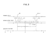
- the interpolation pulses generated as the object of position detection moves in response to the movement command are counted until the first feedback pulse B + 1 after the power is turned on is generated, and the number a of the generated pulses is stored.
- Fig. 2 shows an absolute position detecting apparatus according to an embodiment of the present invention.
- This position detecting apparatus comprises a position detecting unit 10 of, e.g., an optical type, which is operatively coupled to an object of position detection (not shown).
- the detecting unit 10 is arranged so as to deliver a feedback wave (not shown) composed of two sine-wave signals which are generated individually with a period corresponding to the movement of the object of position detection for the first predetermined distance, e.g., 2 um, and whose phases are deviated at an angle of 90 0 from each other.
- the respective feedback wave input terminals of a feedback pulse generating circuit 1 and an interpolation pulse generating circuit 3 are connected to a feedback wave output terminal of the detecting unit 10.
- the feedback pulse generating circuit 1 is provided so as to generate feedback pulses (two of which are designated by symbols B and B + 1 in Fig. 3) of polarity corresponding to the moving direction of the object of detection, with the same period for the feedback wave, that is, each time the object of detection moves for 2 ⁇ m.
- the interpolation pulse generating circuit 3 is provided so as to generate interpolation pulses (designated by symbols C0, C1, C2, ---, C19 in Fig. 3) of polarity corresponding to the moving direction of the object of detection, each time the object of detection moves for the second predetermined distance, e.g., 0.1 gm.
- the position detecting apparatus further comprises an absolute counter 2, an interpolation pulse counter 4, and a correction counter 5.
- the absolute counter 2 has a feedback pulse input terminal connected to the output terminal of the feedback pulse generating circuit 1, and serves to count feedback pulses supplied from the circuit 1.
- the interpolation pulse counter 4 has a reset signal input terminal and an interpolation pulse input terminal connected to the output terminals of the circuits 1 and 3, respectively, and serves to count interpolation pulses.
- the correction counter 5 has a strobe signal input terminal and an interpolation pulse input terminal connected to the output terminals of the circuits 1 and 3, respectively, and serves to temporarily store the number of interpolation pulses supplied from the circuit 3 until the feedback pulses are generated.
- the absolute counter 2 enjoys battery-backup.
- the position detecting apparatus is connected to a numerical control unit 20, as external calculating means, which receives count values of counters 2, 4 and 5, and calculates the power-on absolute value of the object of position detection, as mentioned later.
- a numerical control unit 20 as external calculating means, which receives count values of counters 2, 4 and 5, and calculates the power-on absolute value of the object of position detection, as mentioned later.
- the elements 1 to 5, 10 and 20 can be composed of conventional means, a detailed description thereof is omitted herein.
- suitable circuit means are provided between the elements 1 and 4 and between the elements 1 and 5.
- the object of position detection is in the absolute position designated by symbol P in Fig. 3, and the absolute counter 2 is stored with a count value B, e.g., 100, which indicates that the absolute position P is within the region between B and B + 1 (200 ⁇ m ⁇ P ⁇ 202 ⁇ m).
- the stored values in the interpolation pulse counter 4 and the correction counter 5, which are not subject to battery-backup, are reset to a value "0" when the power is off.
- the object of position detection moves correspondingly, two sine-wave signals are outputted from the detecting unit 10 of the position detecting apparatus.
- an interpolation pulse is delivered from the interpolation pulse generating circuit 3 which receives those sine-wave signals. Every time each interpolation pulse is supplied, the count values in the interpolation pulse counter 4 and the correction counter 5, which individually receive the interpolation pulse, are incremented.
- the first feedback pulse (designated by symbol B + 1 in Fig. 3) is generated from the feedback pulse generating circuit 1, which receives the sine-wave signals from the detecting unit 10, after the power is turned on, this feedback pulse is supplied to the reset signal input terminal of the interpolation pulse counter 4 and the strobe signal input terminal of the correction counter 5 with a required timing.
- the counted value (designated by symbol a in Fig. 3) stored in the correction counter 5 when the feedback pulse is generated is latched in the correction counter, and the interpolation pulse counter 4 is then reset.
- the calculation equation P Bk + (N - a)m corresponding to the positive moving direction
- the calculated value of the power-on absolute position P of the object of position detection is 200.9 um.
- the stored values in the absolute counter 2 and the interpolation pulse counter 4 are updated, respectively, and the stored value in the counter 4 is reset with the generation of each feedback pulse.
- the numerical control unit 20 monitors the actual absolute position of the object of position control, and determines the arrival at the command position.
- Y 150 ⁇ m
- the absolute position of the object of position detection when and after the power is turned on, is calculated by means of the numerical control unit 20, on the basis of the outputs from the corresponding counters.
- calculating means (not shown), which is contained in the absolute position detecting apparatus and having the required calculating function, may be used for this purpose.
Landscapes
- Physics & Mathematics (AREA)
- General Physics & Mathematics (AREA)
- Engineering & Computer Science (AREA)
- Theoretical Computer Science (AREA)
- Transmission And Conversion Of Sensor Element Output (AREA)
- Length Measuring Devices With Unspecified Measuring Means (AREA)
- Optical Transform (AREA)
Applications Claiming Priority (2)
| Application Number | Priority Date | Filing Date | Title |
|---|---|---|---|
| JP368/87 | 1987-02-21 | ||
| JP62036887A JPS63205507A (ja) | 1987-02-21 | 1987-02-21 | アブソリユ−ト位置検出方式 |
Publications (1)
| Publication Number | Publication Date |
|---|---|
| EP0303711A1 true EP0303711A1 (de) | 1989-02-22 |
Family
ID=12482289
Family Applications (1)
| Application Number | Title | Priority Date | Filing Date |
|---|---|---|---|
| EP88901924A Withdrawn EP0303711A1 (de) | 1987-02-21 | 1988-02-19 | Verfahren und gerät zum nachweis der absoluten ortung |
Country Status (4)
| Country | Link |
|---|---|
| US (1) | US4897647A (de) |
| EP (1) | EP0303711A1 (de) |
| JP (1) | JPS63205507A (de) |
| WO (1) | WO1988006277A1 (de) |
Cited By (1)
| Publication number | Priority date | Publication date | Assignee | Title |
|---|---|---|---|---|
| EP3141872A1 (de) * | 2015-09-10 | 2017-03-15 | Dewesoft d.o.o. | Verfahren und vorrichtung zur datenerfassung einer zählvorrichtung, die von einem sensor abgegebene impulse misst |
Families Citing this family (7)
| Publication number | Priority date | Publication date | Assignee | Title |
|---|---|---|---|---|
| DE4011411C2 (de) * | 1990-04-09 | 1993-09-30 | Heidenhain Gmbh Dr Johannes | Inkrementales Positionsmeßsystem |
| JPH04125408A (ja) * | 1990-09-17 | 1992-04-24 | Futaba Corp | リニアスケール測長装置 |
| JP2995097B2 (ja) * | 1991-02-22 | 1999-12-27 | 東芝テック株式会社 | 位置検出装置 |
| US5434564A (en) * | 1991-09-30 | 1995-07-18 | Koga Electronics Co., Ltd. | Method and apparatus for producing pulses corresponding in number to the amount of changes in a physicial quantity |
| US5317614A (en) * | 1992-08-26 | 1994-05-31 | Silicon Systems, Inc. | Programmable electronic angular position indicator based upon engineering units |
| JPH09273942A (ja) * | 1996-02-05 | 1997-10-21 | Aisin Seiki Co Ltd | センサ出力補間方法 |
| DE102004046803B4 (de) * | 2004-09-27 | 2011-08-18 | Infineon Technologies AG, 81669 | Verfahren zur Bestimmung der Winkelposition eines rotierenden Objekts und Drehgeber |
Family Cites Families (5)
| Publication number | Priority date | Publication date | Assignee | Title |
|---|---|---|---|---|
| JPS4849543A (de) * | 1971-10-20 | 1973-07-12 | ||
| JPS5325448A (en) * | 1976-08-20 | 1978-03-09 | Futaba Denshi Kogyo Kk | Position reading apparatus |
| JPH0665967B2 (ja) * | 1985-08-27 | 1994-08-24 | 株式会社エスジー | アブソリュート回転位置検出装置 |
| EP0231474B1 (de) * | 1985-12-16 | 1990-09-05 | Siemens Aktiengesellschaft | Einrichtung zur Absolutwegerfassung |
| US4795927A (en) * | 1986-05-02 | 1989-01-03 | Mitsubishi Jukogyo Kabushiki Kaisha | Control system for a magnetic type bearing |
-
1987
- 1987-02-21 JP JP62036887A patent/JPS63205507A/ja active Pending
-
1988
- 1988-02-19 WO PCT/JP1988/000177 patent/WO1988006277A1/ja not_active Ceased
- 1988-02-19 EP EP88901924A patent/EP0303711A1/de not_active Withdrawn
- 1988-02-19 US US07/251,377 patent/US4897647A/en not_active Expired - Fee Related
Non-Patent Citations (1)
| Title |
|---|
| See references of WO8806277A1 * |
Cited By (2)
| Publication number | Priority date | Publication date | Assignee | Title |
|---|---|---|---|---|
| EP3141872A1 (de) * | 2015-09-10 | 2017-03-15 | Dewesoft d.o.o. | Verfahren und vorrichtung zur datenerfassung einer zählvorrichtung, die von einem sensor abgegebene impulse misst |
| US10352733B2 (en) | 2015-09-10 | 2019-07-16 | DEWESoft | Process and device for acquisition of data of a counting device measuring pulses delivered by a sensor |
Also Published As
| Publication number | Publication date |
|---|---|
| WO1988006277A1 (fr) | 1988-08-25 |
| JPS63205507A (ja) | 1988-08-25 |
| US4897647A (en) | 1990-01-30 |
Similar Documents
| Publication | Publication Date | Title |
|---|---|---|
| EP0035900B1 (de) | Vorrichtung zur Erzeugung eines demodulierten Resolverausgangssignals | |
| WO1995014906A2 (en) | Modular laser gyro | |
| US4897647A (en) | Method for absolute position detection and an apparatus therefore | |
| EP0301382A2 (de) | Kontinuierlich zählende Einrichtung | |
| US4940117A (en) | Procedure for the tuning of the position controller of an elevator | |
| KR930002719B1 (ko) | 인코더 출력의 정확도를 증가시키는 방법 및 장치 | |
| EP0058050A1 (de) | Frequenzmessverfahren | |
| US5477174A (en) | Ramp generator | |
| RU2127867C1 (ru) | Способ динамического измерения угловых перемещений | |
| EP0690973B1 (de) | Schwingbewegungsantrieb für laserkreisel | |
| JPH0469079A (ja) | モータ速度検出装置 | |
| CA2152799C (en) | Laser gyro direct dither drive | |
| SU1702165A1 (ru) | Преобразователь линейных перемещений | |
| SU1721434A1 (ru) | Емкостно-электронный преобразователь перемещени | |
| JPH01314016A (ja) | デイジタルサーボシステムの入力信号変換方法 | |
| JPH0570134B2 (de) | ||
| SU1647446A1 (ru) | Устройство изменени фазового сдвига | |
| JPH0738971Y2 (ja) | 位置決め装置 | |
| KR940004954B1 (ko) | 엔코더형 모터의 속도 검출장치 및 방법 | |
| SU1486944A1 (ru) | Устройство для индикации отклонения переменного напряжения | |
| SU1416991A1 (ru) | Устройство дл ввода информации от дифференциальных датчиков | |
| JPH0785113B2 (ja) | プラズマ位置形状検出装置 | |
| SU1405116A1 (ru) | Способ интегрирующего аналого-цифрового преобразовани | |
| SU1203699A1 (ru) | Способ измерени динамических характеристик преобразовани быстродействующих и высокоточных аналого-цифровых преобразователей и устройство дл его осуществлени | |
| SU1732287A1 (ru) | Способ измерени относительной разности амплитуд двух гармонических напр жений |
Legal Events
| Date | Code | Title | Description |
|---|---|---|---|
| PUAI | Public reference made under article 153(3) epc to a published international application that has entered the european phase |
Free format text: ORIGINAL CODE: 0009012 |
|
| 17P | Request for examination filed |
Effective date: 19880915 |
|
| AK | Designated contracting states |
Kind code of ref document: A1 Designated state(s): DE FR GB |
|
| 18W | Application withdrawn |
Withdrawal date: 19900106 |
|
| STAA | Information on the status of an ep patent application or granted ep patent |
Free format text: STATUS: THE APPLICATION HAS BEEN WITHDRAWN |
|
| R18W | Application withdrawn (corrected) |
Effective date: 19900106 |