EP3143861B1 - Faucheuse et attelage tracté et procédé de fonctionnement de la faucheuse - Google Patents
Faucheuse et attelage tracté et procédé de fonctionnement de la faucheuse Download PDFInfo
- Publication number
- EP3143861B1 EP3143861B1 EP16188457.2A EP16188457A EP3143861B1 EP 3143861 B1 EP3143861 B1 EP 3143861B1 EP 16188457 A EP16188457 A EP 16188457A EP 3143861 B1 EP3143861 B1 EP 3143861B1
- Authority
- EP
- European Patent Office
- Prior art keywords
- mower
- unit
- sub
- working position
- units
- Prior art date
- Legal status (The legal status is an assumption and is not a legal conclusion. Google has not performed a legal analysis and makes no representation as to the accuracy of the status listed.)
- Active
Links
Images
Classifications
-
- A—HUMAN NECESSITIES
- A01—AGRICULTURE; FORESTRY; ANIMAL HUSBANDRY; HUNTING; TRAPPING; FISHING
- A01D—HARVESTING; MOWING
- A01D34/00—Mowers; Mowing apparatus of harvesters
- A01D34/01—Mowers; Mowing apparatus of harvesters characterised by features relating to the type of cutting apparatus
- A01D34/412—Mowers; Mowing apparatus of harvesters characterised by features relating to the type of cutting apparatus having rotating cutters
- A01D34/63—Mowers; Mowing apparatus of harvesters characterised by features relating to the type of cutting apparatus having rotating cutters having cutters rotating about a vertical axis
- A01D34/64—Mowers; Mowing apparatus of harvesters characterised by features relating to the type of cutting apparatus having rotating cutters having cutters rotating about a vertical axis mounted on a vehicle, e.g. a tractor, or drawn by an animal or a vehicle
- A01D34/66—Mowers; Mowing apparatus of harvesters characterised by features relating to the type of cutting apparatus having rotating cutters having cutters rotating about a vertical axis mounted on a vehicle, e.g. a tractor, or drawn by an animal or a vehicle with two or more cutters
- A01D34/661—Mounting means
Definitions
- the invention relates to an agricultural mower according to the preamble of claim 1. Furthermore, the invention relates to an agricultural train with such an agricultural mower and a method for transferring the agricultural mower between a working position and a transport position.
- An agricultural wagon has an agricultural towing vehicle and an agricultural trailer hitch pulled by the towing vehicle.
- the agricultural towing vehicle is typically a tractor.
- the trailed agricultural vehicle towed by the towing vehicle may be a rake, a turner, a mower, or any other towing vehicle towed by the towing vehicle which has a large working width so that the hitch, in its working position, projects laterally clear of the towing vehicle.
- the present invention relates in particular to a trained as a rear mower agricultural trailer device. To be able to transport the agricultural trailer device with the help of the towing vehicle after working on public roads, the implement from the working position out into the transport position is displaced, the towbar in the transport position must not exceed a defined width.
- the mowing units of Heckmähwerks are either a driving direction parallel axis from a horizontal orientation in a vertical orientation upwards displaced or alternatively can be moved backwards over a vertical axis so that the mowing units of the rear mower are parallel to the direction of travel.
- Mowing units of the rear mower as such are designed as rigid units.
- a five-piece mower consisting of a central mower section and right and left inner Mähwerksabêten which are pivotally mounted at their inner edges to corresponding outer edges of the central Mähwerksabitess, and right and left outer Mähtechniksabroughen, at their inner edges at corresponding right and left outer edges of the right and left inner mower sections are pivotally mounted, wherein a transport mechanism first folds the outer wings up and then folds the inner wings to an upright position above the outer edges of the middle section.
- the present invention seeks to provide a novel agricultural mower and a novel agricultural train and a method for transferring the agricultural mower between the working position and the transport position.
- an agricultural mower especially in the form of a rear mower, is proposed for the first time, which mowing units includes, which are not designed as a rigid units, but rather on relative to each other movable Mähteilechen have.
- the respective mowing unit in the working position is displaceable about a first approximately horizontal axis to the respective inner mowing unit, the respective outer and inner Mähteilech, together in the same pivoting direction about a second approximately extending in the direction of travel, are displaceable approximately horizontal axis.
- the respective working mower subunit unit is pivotable to the respective inner mower subunit between a horizontal position laterally disposed therefrom and a horizontal position above it, wherein in the region of each mower unit the respective outer and inner mower subunits are common between a horizontal position, in FIG in which the respective working mower-part unit is arranged above the respective inner mower unit, and a vertical position in which the outer working position Mower unit units facing each other and the inner mower subunits are facing away from each other, are displaced.
- a particularly advantageous displacement of the mower between the working position and the transport position is possible.
- the tension according to the invention is defined in claim 8.
- the inventive method for transferring the agricultural mower between a working position and a transport position is defined in claim 10.
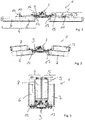
- Fig. 1 to 3 each show views from behind on an inventive, designed as a rear mower 1 agricultural mower.
- Fig. 1 shows the rear mower 1 in a working position
- Fig. 3 shows the rear mower 1 in a transport position
- Fig. 2 shows the rear mower 1 in an intermediate position between the working position and the transport position.
- the rear mower 1 can be coupled to the rear of a towing vehicle, not shown, via a coupling device 2 which engages a support element 3 of the rear mower 1.
- the rear mower 1 has a first mowing unit 4, projecting in the working position of the rear mower 1 on a first side of the towing vehicle relative to the same transverse to the direction of travel, and a second mowing unit 5, the working position on a second side of the towing vehicle relative to the same transverse to the direction of travel protrudes.
- the first mowing unit 4 has an internal mowing unit 6 in the working position and an mowing unit 8 in the working position.
- the second mowing unit 5 has a mowing unit 7 which is located in the working position and an mowing unit 9 in the working position.
- each mowing unit 4 and 5 the respective working mowing unit 8 or 9 is displaceable relative to the respective inner mowing unit 6 or 7 in a defined pivoting direction about a first approximately horizontal axis 10 or 11 extending in the direction of travel.
- the axes 10, 11 are almost parallel to the direction of travel and almost horizontal.
- the axes 10, 11 - viewed in a plan view - include an angle of up to +/- 25 ° with the direction of travel.
- the axes 10, 11 can be inclined relative to the horizontal by up to +/- 5 °.
- each mowing unit 4, 5 the respective outer and inner Mähteilhow 6 and 8 or 7 and 9 together in the same pivoting direction about a second extending approximately in the direction of travel, approximately horizontal axis 12 and 13 displaced, preferably relative to the support element 3.
- the axes 12, 13 are almost parallel to the direction of travel and almost horizontal.
- the axes 12, 13 - viewed in a plan view - include an angle of up to +/- 25 ° with the direction of travel.
- Fig. 1 arrows 14, 15, 16 and 17 illustrate the respective pivoting directions about the above axes 10, 11, 12 and 13.
- the mowing unit 8 in working position is displaceable about the axis 10 to the inner mowing unit 6 in the pivoting direction 14, the outer and inner Mähteilhow 6, 8 are displaceable together in the same pivoting direction 16 about the second axis 12 ,
- the outer mowing unit 9 is displaceable relative to the inner mowing unit 7 in the pivoting direction 17 about the first axis 11, furthermore In turn, both mowing units 7, 9 are displaceable together in the same pivoting direction 15 about the second axis 13.
- the pivoting directions 14, 16 within the first mowing unit 4 run in opposite directions to the pivoting directions 15, 17 of the second mowing unit 5.
- each mowing unit 4 5
- the respective working mowing unit 8 or 9 is pivotable or displaceable relative to the respective inner mowing unit 6 or 7 between a horizontal position laterally disposed therefrom and a horizontal position disposed above it Fig. 2 can be taken immediately.
- each mowing unit 4, 5 the outer and inner mowing unit 6, 8 and 7, 9 together between the horizontal position of Fig. 2 in which the respective working mowing unit 6 or 9 is arranged above the respective inner mowing unit 6 or 7, and the in Fig. 3 shown displaced in the vertical position, wherein in the vertical position of the Fig. 3 the outer mowing units 8, 9 in the working position face each other and the working mowing units 6, 7 facing away from each other in the working position.
- the orientation of the mowing units 6, 8 and 7, 9 of the mower units 4 and 5 changes relative to each other, so that accordingly in the working position outer Mähteilhowen 8, 9 of the transport position are positioned inside.
- the outer mowing units 8, 9 are angularly offset on the inner Mähteilhowen 6 and 7, so that when moving the Mähteilhowen 6, 8 or 7, 9 results in the vertical position in the middle region a free space.
- This advantageous free space can be used for the support structure 3, for drive elements and / or for control elements.
- each mowing unit 4, 5 the respective working mowing unit 8 or 9 can be pivoted to the respective inner mowing unit 6, 7 by approximately 180 °, furthermore in the area of each mowing unit 4, 5 the two Mowing units 6, 8 and 7, 9 are displaced together by about 90 °.
- These angles refer to ideal ground conditions in which the towing vehicle is perpendicular and the mowing units run horizontally thereto. In uneven ground conditions, where mowing units have adapted, for example, a bottom inclination, these adjustment angles may need to be added to or subtracted from the above-mentioned pivoting angles.
- the mowing units 6, 8 and 7, 9 in the region of each mowing unit 4, 5 may be offset from each other in such a way that the same seen in the direction of travel have an offset, so that seen in the direction of travel, for example, the outer Mowing units 8, 9 are positioned in front of or behind the inner Mähteilizien 6, 7.
- the invention further relates to a train of a tractor and such preferably designed as a rear mower 1 mower.
- the invention relates to a method for transferring the rear mower 1 described above between the working position and the transport position.
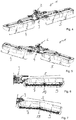
- FIG. 5 to 7 Another special feature of the rear mower 1 according to the invention follows in particular Fig. 5 to 7 , So can Fig. 5 to 7 , So can Fig. 5 to 7 , So can Fig. 5 to 7 It can be seen that in the area of each mowing unit 4, 5 in the working position, the mowing unit units 6, 8 and 7, 9 are displaceable relative to each other to a defined extent, namely about a pivot 18, so as to allow adaptation to uneven floors. In the Working position of the rear mower 1, this pivot 18 is coupled to the respective subunits 6, 8 and 7, 9 and thus locked in a working position to allow the ground adjustment.
- the - aligned approximately parallel to the direction of travel - axis of rotation of the rotary joint 18 is preferably arranged approximately in the sectional plane of the mowing units 6,8 or 7, 9.
Landscapes
- Life Sciences & Earth Sciences (AREA)
- Environmental Sciences (AREA)
- Harvester Elements (AREA)
Claims (10)
- Tête de fauchage agricole (1) pour un véhicule tracteur agricole, laquelle peut être couplée au véhicule tracteur et déplacée par le véhicule tracteur, la tête de fauchage (1) comportant une première unité de tête de fauchage (4), qui, dans une position de travail de la tête de fauchage (1), dépasse du véhicule tracteur transversalement au sens de la marche sur un premier côté de celui-ci, et une seconde unité de tête de fauchage (5) qui, dans la position de travail de la tête de fauchage (1), dépasse du véhicule tracteur transversalement au sens de la marche sur un second côté de celui-ci, et les unités de tête de fauchage étant translatables entre la position de travail et une position de transport, la première unité de tête de fauchage (4) et la seconde unité de tête de fauchage (5) comportant chacune une unité partielle de tête de fauchage (6, 7) intérieure dans la position de travail et une unité partielle de tête de fauchage (8, 9) extérieure dans la position de travail, dans la zone de chaque unité de tête de fauchage (4, 5) l'unité partielle de tête de fauchage respectivement extérieure (8, 9) étant déplaçable dans une direction de pivotement définie (14, 17) autour d'un premier axe (10, 11) par rapport à l'unité partielle de tête de fauchage respectivement intérieure (6, 7) de même que les unités partielles de tête de fauchage respectivement extérieure et intérieure (6, 7, 8, 9) sont déplaçables conjointement dans la même direction de pivotement (16, 15) autour d'un second axe (12, 13), dans la zone de la première unité de tête de fauchage (4) l'unité partielle de tête de fauchage (8) respectivement extérieure dans la position de travail pouvant pivoter autour du premier axe respectif (10) par rapport à l'unité partielle de tête de fauchage intérieure (6) de même que les unités partielles de tête de fauchage extérieure et intérieure (6, 8) peuvent pivoter conjointement dans la même direction autour du second axe respectif (12), et dans la zone de la seconde unité de tête de fauchage (5) l'unité partielle de tête de fauchage (9) respectivement extérieure dans la position de travail pouvant pivoter autour du premier axe respectif (11) par rapport à l'unité partielle de tête de fauchage intérieure (7) de même que les unités partielles de tête de fauchage extérieure et intérieure (7, 9) peuvent pivoter conjointement dans la même direction autour du second axe respectif (13), les directions de pivotement de la première unité de tête de fauchage (4) étant contraires aux directions de pivotement de l'unités de tête de fauchage (5), caractérisée en ce que, dans la zone de chaque unité de tête de fauchage (4, 5), l'unité partielle de tête de fauchage (8, 9) respectivement extérieure dans la position de travail peut pivoter par rapport à l'unité partielle de tête de fauchage (6, 7) respectivement intérieure entre une position horizontale disposée latéralement à côté de celle-ci et une position horizontale disposée au-dessus de celle-ci.
- Tête de fauchage selon la revendication 1, caractérisée en ce que dans la zone de chaque unité de tête de fauchage (4, 5), l'unité partielle de tête de fauchage (8, 9) respectivement extérieure dans la position de travail peut pivoter d'environ 180° par rapport à l'unité partielle de tête de fauchage (7, 9) respectivement inférieure.
- Tête de fauchage selon une des revendications 1 à 2, caractérisée en ce que dans la zone de chaque unité de tête de fauchage (4, 5) les unités partielles de tête de fauchage respectivement extérieure et intérieure (6, 8, 7, 9) sont translatables conjointement entre une position horizontale, dans laquelle l'unité partielle de tête de fauchage (6, 8) respectivement extérieure dans la position de travail est disposée au-dessus de l'unité partielle de tête de fauchage (7, 9) respectivement intérieure, et une position verticale dans laquelle les unités partielles de tête de fauchage (8, 9) extérieures dans la position de travail sont orientées l'une vers l'autre et les unités partielles de tête de fauchage intérieures (7) sont orientées à l'opposé l'une de l'autre.
- Tête de fauchage selon une des revendications 1 à 3, caractérisée en ce que dans la zone de chaque unité de tête de fauchage (4, 5) l'unité partielle de tête de fauchage (8, 9) respectivement extérieure et l'unité partielle de tête de fauchage (6, 7) intérieure sont déplaçables conjointement d'environ 90° à 100°.
- Tête de fauchage selon une des revendications 1 à 4, caractérisée en ce que dans la zone de chaque unité de tête de fauchage (4, 5), les unités partielles de tête de fauchage (6, 8, 7, 9) dans la position de travail sont déplaçables l'une par rapport à l'autre pour s'adapter aux irrégularités du sol.
- Tête de fauchage selon une des revendications 1 à 5, caractérisée en ce qu'elle comporte une tête de fauchage arrière (1) avec une première et une seconde unité de fauchage latérale (4, 5), chacune des unités de fauchage comprenant une unité de fauchage intérieure et extérieure (6, 8, 7, 9).
- Tête de fauchage selon une des revendications précédentes, caractérisée en ce que les premier et second axes (10, 11 ; 12, 13) s'étendent sensiblement dans le sens de la marche ou forment avec le sens de la marche respectivement un angle d'au plus +/-25° et/ou sont orientés sensiblement horizontalement ou inclinés par rapport à l'horizontale d'au plus +/-5°.
- Attelage agricole tracté comprenant un véhicule tracteur agricole et comprenant une tête de fauchage agricole (1) montée sur le véhicule tracteur, caractérisé en ce que la tête de fauchage (1) est conformée selon une des revendications 1 à 7.
- Attelage tracté selon la revendication 8, caractérisé en ce que, dans la position de transport, la tête de fauchage (1) peut être abaissée et levée par l'intermédiaire d'un mécanisme de levage du véhicule tracteur.
- Procédé de transfert d'une tête de fauchage agricole (1) selon une des revendications 1 à 7 entre une position de travail et une position de transport, la tête de fauchage (1) comportant une première unité de tête de fauchage (4), qui, dans une position de travail, dépasse du véhicule tracteur transversalement au sens de la marche sur un premier côté de celui-ci, et une seconde unité de tête de fauchage (5) qui, dans la position de travail, dépasse du véhicule tracteur transversalement au sens de la marche sur un second côté de celui-ci, et les unités de tête de fauchage (4, 5) comportant chacune une unité partielle de tête de fauchage (6, 7) intérieure dans la position de travail et une unité partielle de tête de fauchage (8, 9) extérieure dans la position de travail, comprenant les étapes suivantes :pour transférer la tête de fauchage (1) depuis la position de travail vers la position de transport, dans la zone de chaque unité de tête de fauchage (4, 5), l'unité partielle de tête de fauchage (8, 9) respective extérieure, dans la position de travail, est déplacée dans une direction de pivotement définie (14, 17) autour du premier axe (10, 11) par rapport à l'unité partielle de tête de fauchage (6, 7) respective intérieure et pivote ainsi d'une position horizontale disposée latéralement à côté de celle-ci vers une position horizontale disposée au-dessus de celle-ci, les unités partielles de tête de fauchage extérieure et intérieure étant ensuite déplacées conjointement dans la même direction de pivotement autour du second axe (12, 13) ;pour transférer la tête de fauchage (1) depuis la position de transport vers la position de travail, dans la zone de chaque unité de tête de fauchage (4, 5), les unités partielles de tête de fauchage extérieure et intérieure sont déplacées conjointement dans une direction de pivotement autour du second axe (12, 13), l'unité partielle de tête de fauchage (8, 9) respectivement extérieure dans la position de travail étant ensuite transférée dans la même direction de pivotement autour du premier axe (10, 11) par rapport à l'unité partielle de tête de fauchage (6, 7) respective intérieure.
Priority Applications (2)
| Application Number | Priority Date | Filing Date | Title |
|---|---|---|---|
| SI201630492T SI3143861T1 (sl) | 2015-09-18 | 2016-09-13 | Kmetijska kosilnica in vlečna vprega ter postopek za delovanje kosilnice |
| PL16188457T PL3143861T3 (pl) | 2015-09-18 | 2016-09-13 | Kosiarka rolnicza i zespół ciągnikowy oraz sposób eksploatacji kosiarki |
Applications Claiming Priority (1)
| Application Number | Priority Date | Filing Date | Title |
|---|---|---|---|
| DE102015115829.9A DE102015115829A1 (de) | 2015-09-18 | 2015-09-18 | Landwirtschaftliches Mähwerk und Zuggespann und Verfahren zum Betreiben des Mähwerks |
Publications (3)
| Publication Number | Publication Date |
|---|---|
| EP3143861A1 EP3143861A1 (fr) | 2017-03-22 |
| EP3143861B1 true EP3143861B1 (fr) | 2019-08-21 |
| EP3143861B2 EP3143861B2 (fr) | 2022-06-08 |
Family
ID=56920605
Family Applications (1)
| Application Number | Title | Priority Date | Filing Date |
|---|---|---|---|
| EP16188457.2A Active EP3143861B2 (fr) | 2015-09-18 | 2016-09-13 | Faucheuse et attelage tracté et procédé de fonctionnement de la faucheuse |
Country Status (5)
| Country | Link |
|---|---|
| EP (1) | EP3143861B2 (fr) |
| DE (1) | DE102015115829A1 (fr) |
| DK (1) | DK3143861T3 (fr) |
| PL (1) | PL3143861T3 (fr) |
| SI (1) | SI3143861T1 (fr) |
Cited By (1)
| Publication number | Priority date | Publication date | Assignee | Title |
|---|---|---|---|---|
| US20200329640A1 (en) * | 2019-04-18 | 2020-10-22 | Maschinenfabrik Bernard Krone GmbH & Co. KG | Mowing Machine |
Families Citing this family (3)
| Publication number | Priority date | Publication date | Assignee | Title |
|---|---|---|---|---|
| EP3928612A1 (fr) | 2020-06-25 | 2021-12-29 | Pöttinger Landtechnik GmbH | Engin agricole |
| DE102020124362A1 (de) | 2020-06-25 | 2021-12-30 | Pöttinger Landtechnik Gmbh | Landwirtschaftliche Maschine |
| FR3126593B1 (fr) * | 2021-09-07 | 2023-09-08 | Kuhn Sas | Dispositif agricole à deux unités de travail |
Citations (4)
| Publication number | Priority date | Publication date | Assignee | Title |
|---|---|---|---|---|
| EP1179289A2 (fr) | 2000-08-09 | 2002-02-13 | Deere & Company | Outil pliable de travail agricole |
| US20070119139A1 (en) | 2005-11-25 | 2007-05-31 | Todd Hofmann | Five-section rotary mower |
| WO2011045610A1 (fr) | 2009-10-16 | 2011-04-21 | Spearhead Machinery Limited | Faucheuse rotative |
| WO2015075356A1 (fr) | 2013-11-22 | 2015-05-28 | Kuhn S.A. | Machine agricole, notamment machine pour la recolte de vegetaux, comportant deux unites de travail animees articulees a un meme bras lateral |
Family Cites Families (5)
| Publication number | Priority date | Publication date | Assignee | Title |
|---|---|---|---|---|
| US3473302A (en) * | 1967-04-14 | 1969-10-21 | Caldwell & Sons Inc E L | Tractor drawn multiple section foldable mower |
| DE29817666U1 (de) * | 1998-10-05 | 1998-12-10 | Maschinenfabrik Kemper GmbH & Co. KG, 48703 Stadtlohn | Maschine zum Mähen von Mais u.dgl. stengelartigem Erntegut |
| DE19856907A1 (de) * | 1998-12-10 | 2000-06-15 | Amazonen Werke Dreyer H | Werkzeugträger |
| DE10157289A1 (de) * | 2001-11-22 | 2003-06-05 | Claas Saulgau Gmbh | Mähwerk mit wenigstens zwei gekoppelten Mähbalken |
| HUP0300512A2 (hu) | 2002-03-28 | 2004-09-28 | Claas Saulgau Gmbh | Kaszáló berendezés |
-
2015
- 2015-09-18 DE DE102015115829.9A patent/DE102015115829A1/de not_active Withdrawn
-
2016
- 2016-09-13 DK DK16188457T patent/DK3143861T3/da active
- 2016-09-13 EP EP16188457.2A patent/EP3143861B2/fr active Active
- 2016-09-13 SI SI201630492T patent/SI3143861T1/sl unknown
- 2016-09-13 PL PL16188457T patent/PL3143861T3/pl unknown
Patent Citations (4)
| Publication number | Priority date | Publication date | Assignee | Title |
|---|---|---|---|---|
| EP1179289A2 (fr) | 2000-08-09 | 2002-02-13 | Deere & Company | Outil pliable de travail agricole |
| US20070119139A1 (en) | 2005-11-25 | 2007-05-31 | Todd Hofmann | Five-section rotary mower |
| WO2011045610A1 (fr) | 2009-10-16 | 2011-04-21 | Spearhead Machinery Limited | Faucheuse rotative |
| WO2015075356A1 (fr) | 2013-11-22 | 2015-05-28 | Kuhn S.A. | Machine agricole, notamment machine pour la recolte de vegetaux, comportant deux unites de travail animees articulees a un meme bras lateral |
Cited By (2)
| Publication number | Priority date | Publication date | Assignee | Title |
|---|---|---|---|---|
| US20200329640A1 (en) * | 2019-04-18 | 2020-10-22 | Maschinenfabrik Bernard Krone GmbH & Co. KG | Mowing Machine |
| US11641793B2 (en) * | 2019-04-18 | 2023-05-09 | Maschinenfabrik Bernard Krone GmbH & Co. KG | Mowing machine comprising a cutterbar with a pivotable lateral section |
Also Published As
| Publication number | Publication date |
|---|---|
| SI3143861T1 (sl) | 2019-12-31 |
| EP3143861A1 (fr) | 2017-03-22 |
| DE102015115829A1 (de) | 2017-03-23 |
| DK3143861T3 (da) | 2019-11-18 |
| PL3143861T3 (pl) | 2020-02-28 |
| EP3143861B2 (fr) | 2022-06-08 |
Similar Documents
| Publication | Publication Date | Title |
|---|---|---|
| EP2186713B1 (fr) | Dispositif de ballastage et véhicule agricole équipé avec ce dernier | |
| EP3143861B1 (fr) | Faucheuse et attelage tracté et procédé de fonctionnement de la faucheuse | |
| DE19534695C2 (de) | An einem Schlepper ansetzbares Heckmähwerk | |
| EP3028557B1 (fr) | Faucheuse et procédé de fonctionnement d'une faucheuse | |
| EP3251480B1 (fr) | Remorque et ensemble attelé comprenant un véhicule tracteur et une remorque | |
| DE3121745A1 (de) | "lastzug" | |
| AT516017A2 (de) | Fahrzeuganhänger mit einer hydraulisch lenkbaren Deichsel | |
| DE9312222U1 (de) | Heuwerbungsmaschine | |
| DE202017007208U1 (de) | Transportanhängerverbund und Transportanhängerzug mit mindestens zwei solchen Transportanhängerverbunden | |
| EP0033873B1 (fr) | Train routier à intervalle variable entre tracteur et remorque | |
| DE2141086C3 (de) | Anbaubock zum Anschließen einer Landmaschine an einen Schlepper | |
| DE202008018308U1 (de) | Gezogene landwirtschaftliche Maschine | |
| EP3387891B1 (fr) | Dispositif de traction | |
| EP2640178B1 (fr) | Dispositif pour l'épandage d'engrais selon des bandes | |
| EP3266292B1 (fr) | Outil agricole tracté et agricole et attelage comprenant un tel outil tracté | |
| EP2210473B1 (fr) | Mécanisme de tonte doté d'un dispositif de transport transversal | |
| EP0503395A1 (fr) | Faucheuse | |
| DE602005005143T2 (de) | Heuwerbungsmaschine | |
| DE102012015554A1 (de) | Muldenkipper mit einer Kippermulde | |
| EP3278657B1 (fr) | Chariot de collecte de balles destiné à collecter et à transporter des balles rondes | |
| DE2818359A1 (de) | Schmiegeegge | |
| DE4130829C2 (de) | Anhängevorrichtung für Zugmaschinen | |
| DE10030263A1 (de) | Anhängevorrichtung | |
| EP0381926A2 (fr) | Dispositif d'accouplement d'outils traînés, par exemple des remorques agricoles | |
| EP1782674B1 (fr) | Faucheuse |
Legal Events
| Date | Code | Title | Description |
|---|---|---|---|
| PUAI | Public reference made under article 153(3) epc to a published international application that has entered the european phase |
Free format text: ORIGINAL CODE: 0009012 |
|
| STAA | Information on the status of an ep patent application or granted ep patent |
Free format text: STATUS: THE APPLICATION HAS BEEN PUBLISHED |
|
| AK | Designated contracting states |
Kind code of ref document: A1 Designated state(s): AL AT BE BG CH CY CZ DE DK EE ES FI FR GB GR HR HU IE IS IT LI LT LU LV MC MK MT NL NO PL PT RO RS SE SI SK SM TR |
|
| AX | Request for extension of the european patent |
Extension state: BA ME |
|
| STAA | Information on the status of an ep patent application or granted ep patent |
Free format text: STATUS: REQUEST FOR EXAMINATION WAS MADE |
|
| 17P | Request for examination filed |
Effective date: 20170922 |
|
| RBV | Designated contracting states (corrected) |
Designated state(s): AL AT BE BG CH CY CZ DE DK EE ES FI FR GB GR HR HU IE IS IT LI LT LU LV MC MK MT NL NO PL PT RO RS SE SI SK SM TR |
|
| GRAP | Despatch of communication of intention to grant a patent |
Free format text: ORIGINAL CODE: EPIDOSNIGR1 |
|
| STAA | Information on the status of an ep patent application or granted ep patent |
Free format text: STATUS: GRANT OF PATENT IS INTENDED |
|
| INTG | Intention to grant announced |
Effective date: 20190523 |
|
| GRAS | Grant fee paid |
Free format text: ORIGINAL CODE: EPIDOSNIGR3 |
|
| GRAA | (expected) grant |
Free format text: ORIGINAL CODE: 0009210 |
|
| STAA | Information on the status of an ep patent application or granted ep patent |
Free format text: STATUS: THE PATENT HAS BEEN GRANTED |
|
| AK | Designated contracting states |
Kind code of ref document: B1 Designated state(s): AL AT BE BG CH CY CZ DE DK EE ES FI FR GB GR HR HU IE IS IT LI LT LU LV MC MK MT NL NO PL PT RO RS SE SI SK SM TR |
|
| REG | Reference to a national code |
Ref country code: GB Ref legal event code: FG4D Free format text: NOT ENGLISH |
|
| REG | Reference to a national code |
Ref country code: CH Ref legal event code: EP |
|
| REG | Reference to a national code |
Ref country code: DE Ref legal event code: R096 Ref document number: 502016006168 Country of ref document: DE |
|
| REG | Reference to a national code |
Ref country code: AT Ref legal event code: REF Ref document number: 1168617 Country of ref document: AT Kind code of ref document: T Effective date: 20190915 |
|
| REG | Reference to a national code |
Ref country code: IE Ref legal event code: FG4D Free format text: LANGUAGE OF EP DOCUMENT: GERMAN |
|
| REG | Reference to a national code |
Ref country code: DK Ref legal event code: T3 Effective date: 20191111 |
|
| REG | Reference to a national code |
Ref country code: LT Ref legal event code: MG4D |
|
| REG | Reference to a national code |
Ref country code: NL Ref legal event code: MP Effective date: 20190821 |
|
| PG25 | Lapsed in a contracting state [announced via postgrant information from national office to epo] |
Ref country code: NO Free format text: LAPSE BECAUSE OF FAILURE TO SUBMIT A TRANSLATION OF THE DESCRIPTION OR TO PAY THE FEE WITHIN THE PRESCRIBED TIME-LIMIT Effective date: 20191121 Ref country code: HR Free format text: LAPSE BECAUSE OF FAILURE TO SUBMIT A TRANSLATION OF THE DESCRIPTION OR TO PAY THE FEE WITHIN THE PRESCRIBED TIME-LIMIT Effective date: 20190821 Ref country code: FI Free format text: LAPSE BECAUSE OF FAILURE TO SUBMIT A TRANSLATION OF THE DESCRIPTION OR TO PAY THE FEE WITHIN THE PRESCRIBED TIME-LIMIT Effective date: 20190821 Ref country code: SE Free format text: LAPSE BECAUSE OF FAILURE TO SUBMIT A TRANSLATION OF THE DESCRIPTION OR TO PAY THE FEE WITHIN THE PRESCRIBED TIME-LIMIT Effective date: 20190821 Ref country code: PT Free format text: LAPSE BECAUSE OF FAILURE TO SUBMIT A TRANSLATION OF THE DESCRIPTION OR TO PAY THE FEE WITHIN THE PRESCRIBED TIME-LIMIT Effective date: 20191223 Ref country code: LT Free format text: LAPSE BECAUSE OF FAILURE TO SUBMIT A TRANSLATION OF THE DESCRIPTION OR TO PAY THE FEE WITHIN THE PRESCRIBED TIME-LIMIT Effective date: 20190821 Ref country code: NL Free format text: LAPSE BECAUSE OF FAILURE TO SUBMIT A TRANSLATION OF THE DESCRIPTION OR TO PAY THE FEE WITHIN THE PRESCRIBED TIME-LIMIT Effective date: 20190821 Ref country code: BG Free format text: LAPSE BECAUSE OF FAILURE TO SUBMIT A TRANSLATION OF THE DESCRIPTION OR TO PAY THE FEE WITHIN THE PRESCRIBED TIME-LIMIT Effective date: 20191121 |
|
| PG25 | Lapsed in a contracting state [announced via postgrant information from national office to epo] |
Ref country code: IS Free format text: LAPSE BECAUSE OF FAILURE TO SUBMIT A TRANSLATION OF THE DESCRIPTION OR TO PAY THE FEE WITHIN THE PRESCRIBED TIME-LIMIT Effective date: 20191221 Ref country code: LV Free format text: LAPSE BECAUSE OF FAILURE TO SUBMIT A TRANSLATION OF THE DESCRIPTION OR TO PAY THE FEE WITHIN THE PRESCRIBED TIME-LIMIT Effective date: 20190821 Ref country code: GR Free format text: LAPSE BECAUSE OF FAILURE TO SUBMIT A TRANSLATION OF THE DESCRIPTION OR TO PAY THE FEE WITHIN THE PRESCRIBED TIME-LIMIT Effective date: 20191122 Ref country code: RS Free format text: LAPSE BECAUSE OF FAILURE TO SUBMIT A TRANSLATION OF THE DESCRIPTION OR TO PAY THE FEE WITHIN THE PRESCRIBED TIME-LIMIT Effective date: 20190821 Ref country code: ES Free format text: LAPSE BECAUSE OF FAILURE TO SUBMIT A TRANSLATION OF THE DESCRIPTION OR TO PAY THE FEE WITHIN THE PRESCRIBED TIME-LIMIT Effective date: 20190821 Ref country code: AL Free format text: LAPSE BECAUSE OF FAILURE TO SUBMIT A TRANSLATION OF THE DESCRIPTION OR TO PAY THE FEE WITHIN THE PRESCRIBED TIME-LIMIT Effective date: 20190821 |
|
| PG25 | Lapsed in a contracting state [announced via postgrant information from national office to epo] |
Ref country code: TR Free format text: LAPSE BECAUSE OF FAILURE TO SUBMIT A TRANSLATION OF THE DESCRIPTION OR TO PAY THE FEE WITHIN THE PRESCRIBED TIME-LIMIT Effective date: 20190821 |
|
| PG25 | Lapsed in a contracting state [announced via postgrant information from national office to epo] |
Ref country code: RO Free format text: LAPSE BECAUSE OF FAILURE TO SUBMIT A TRANSLATION OF THE DESCRIPTION OR TO PAY THE FEE WITHIN THE PRESCRIBED TIME-LIMIT Effective date: 20190821 Ref country code: EE Free format text: LAPSE BECAUSE OF FAILURE TO SUBMIT A TRANSLATION OF THE DESCRIPTION OR TO PAY THE FEE WITHIN THE PRESCRIBED TIME-LIMIT Effective date: 20190821 Ref country code: IT Free format text: LAPSE BECAUSE OF FAILURE TO SUBMIT A TRANSLATION OF THE DESCRIPTION OR TO PAY THE FEE WITHIN THE PRESCRIBED TIME-LIMIT Effective date: 20190821 |
|
| REG | Reference to a national code |
Ref country code: DE Ref legal event code: R026 Ref document number: 502016006168 Country of ref document: DE |
|
| PG25 | Lapsed in a contracting state [announced via postgrant information from national office to epo] |
Ref country code: SM Free format text: LAPSE BECAUSE OF FAILURE TO SUBMIT A TRANSLATION OF THE DESCRIPTION OR TO PAY THE FEE WITHIN THE PRESCRIBED TIME-LIMIT Effective date: 20190821 Ref country code: CZ Free format text: LAPSE BECAUSE OF FAILURE TO SUBMIT A TRANSLATION OF THE DESCRIPTION OR TO PAY THE FEE WITHIN THE PRESCRIBED TIME-LIMIT Effective date: 20190821 Ref country code: MC Free format text: LAPSE BECAUSE OF FAILURE TO SUBMIT A TRANSLATION OF THE DESCRIPTION OR TO PAY THE FEE WITHIN THE PRESCRIBED TIME-LIMIT Effective date: 20190821 Ref country code: IS Free format text: LAPSE BECAUSE OF FAILURE TO SUBMIT A TRANSLATION OF THE DESCRIPTION OR TO PAY THE FEE WITHIN THE PRESCRIBED TIME-LIMIT Effective date: 20200224 Ref country code: SK Free format text: LAPSE BECAUSE OF FAILURE TO SUBMIT A TRANSLATION OF THE DESCRIPTION OR TO PAY THE FEE WITHIN THE PRESCRIBED TIME-LIMIT Effective date: 20190821 |
|
| PLBI | Opposition filed |
Free format text: ORIGINAL CODE: 0009260 |
|
| REG | Reference to a national code |
Ref country code: CH Ref legal event code: PL |
|
| PLAX | Notice of opposition and request to file observation + time limit sent |
Free format text: ORIGINAL CODE: EPIDOSNOBS2 |
|
| 26 | Opposition filed |
Opponent name: KUHN S.A.S. Effective date: 20200520 |
|
| PG2D | Information on lapse in contracting state deleted |
Ref country code: IS |
|
| PG25 | Lapsed in a contracting state [announced via postgrant information from national office to epo] |
Ref country code: IE Free format text: LAPSE BECAUSE OF NON-PAYMENT OF DUE FEES Effective date: 20190913 Ref country code: CH Free format text: LAPSE BECAUSE OF NON-PAYMENT OF DUE FEES Effective date: 20190930 Ref country code: LU Free format text: LAPSE BECAUSE OF NON-PAYMENT OF DUE FEES Effective date: 20190913 Ref country code: LI Free format text: LAPSE BECAUSE OF NON-PAYMENT OF DUE FEES Effective date: 20190930 |
|
| REG | Reference to a national code |
Ref country code: BE Ref legal event code: MM Effective date: 20190930 |
|
| PG25 | Lapsed in a contracting state [announced via postgrant information from national office to epo] |
Ref country code: BE Free format text: LAPSE BECAUSE OF NON-PAYMENT OF DUE FEES Effective date: 20190930 |
|
| PLBB | Reply of patent proprietor to notice(s) of opposition received |
Free format text: ORIGINAL CODE: EPIDOSNOBS3 |
|
| GBPC | Gb: european patent ceased through non-payment of renewal fee |
Effective date: 20200913 |
|
| PG25 | Lapsed in a contracting state [announced via postgrant information from national office to epo] |
Ref country code: CY Free format text: LAPSE BECAUSE OF FAILURE TO SUBMIT A TRANSLATION OF THE DESCRIPTION OR TO PAY THE FEE WITHIN THE PRESCRIBED TIME-LIMIT Effective date: 20190821 |
|
| PG25 | Lapsed in a contracting state [announced via postgrant information from national office to epo] |
Ref country code: HU Free format text: LAPSE BECAUSE OF FAILURE TO SUBMIT A TRANSLATION OF THE DESCRIPTION OR TO PAY THE FEE WITHIN THE PRESCRIBED TIME-LIMIT; INVALID AB INITIO Effective date: 20160913 Ref country code: MT Free format text: LAPSE BECAUSE OF FAILURE TO SUBMIT A TRANSLATION OF THE DESCRIPTION OR TO PAY THE FEE WITHIN THE PRESCRIBED TIME-LIMIT Effective date: 20190821 |
|
| PG25 | Lapsed in a contracting state [announced via postgrant information from national office to epo] |
Ref country code: GB Free format text: LAPSE BECAUSE OF NON-PAYMENT OF DUE FEES Effective date: 20200913 |
|
| PGFP | Annual fee paid to national office [announced via postgrant information from national office to epo] |
Ref country code: PL Payment date: 20210903 Year of fee payment: 6 |
|
| PUAH | Patent maintained in amended form |
Free format text: ORIGINAL CODE: 0009272 |
|
| STAA | Information on the status of an ep patent application or granted ep patent |
Free format text: STATUS: PATENT MAINTAINED AS AMENDED |
|
| 27A | Patent maintained in amended form |
Effective date: 20220608 |
|
| AK | Designated contracting states |
Kind code of ref document: B2 Designated state(s): AL AT BE BG CH CY CZ DE DK EE ES FI FR GB GR HR HU IE IS IT LI LT LU LV MC MK MT NL NO PL PT RO RS SE SI SK SM TR |
|
| REG | Reference to a national code |
Ref country code: DE Ref legal event code: R102 Ref document number: 502016006168 Country of ref document: DE |
|
| PG25 | Lapsed in a contracting state [announced via postgrant information from national office to epo] |
Ref country code: MK Free format text: LAPSE BECAUSE OF FAILURE TO SUBMIT A TRANSLATION OF THE DESCRIPTION OR TO PAY THE FEE WITHIN THE PRESCRIBED TIME-LIMIT Effective date: 20190821 |
|
| PGFP | Annual fee paid to national office [announced via postgrant information from national office to epo] |
Ref country code: DK Payment date: 20220922 Year of fee payment: 7 |
|
| PG25 | Lapsed in a contracting state [announced via postgrant information from national office to epo] |
Ref country code: DK Free format text: LAPSE BECAUSE OF FAILURE TO SUBMIT A TRANSLATION OF THE DESCRIPTION OR TO PAY THE FEE WITHIN THE PRESCRIBED TIME-LIMIT Effective date: 20220608 |
|
| P01 | Opt-out of the competence of the unified patent court (upc) registered |
Effective date: 20230509 |
|
| PG25 | Lapsed in a contracting state [announced via postgrant information from national office to epo] |
Ref country code: PL Free format text: THE PATENT HAS BEEN ANNULLED BY A DECISION OF A NATIONAL AUTHORITY Effective date: 20220908 |
|
| PG25 | Lapsed in a contracting state [announced via postgrant information from national office to epo] |
Ref country code: PL Free format text: THE PATENT HAS BEEN ANNULLED BY A DECISION OF A NATIONAL AUTHORITY Effective date: 20220908 |
|
| PGFP | Annual fee paid to national office [announced via postgrant information from national office to epo] |
Ref country code: DE Payment date: 20250919 Year of fee payment: 10 |
|
| PGFP | Annual fee paid to national office [announced via postgrant information from national office to epo] |
Ref country code: FR Payment date: 20250922 Year of fee payment: 10 Ref country code: AT Payment date: 20250919 Year of fee payment: 10 |
|
| PGFP | Annual fee paid to national office [announced via postgrant information from national office to epo] |
Ref country code: SI Payment date: 20250904 Year of fee payment: 10 |