EP3144089B1 - Funkenerosionsbearbeitungssystem mit unabhängigen elektroden - Google Patents
Funkenerosionsbearbeitungssystem mit unabhängigen elektroden Download PDFInfo
- Publication number
- EP3144089B1 EP3144089B1 EP16183855.2A EP16183855A EP3144089B1 EP 3144089 B1 EP3144089 B1 EP 3144089B1 EP 16183855 A EP16183855 A EP 16183855A EP 3144089 B1 EP3144089 B1 EP 3144089B1
- Authority
- EP
- European Patent Office
- Prior art keywords
- electrode
- devices
- driver
- electrode devices
- guide structure
- Prior art date
- Legal status (The legal status is an assumption and is not a legal conclusion. Google has not performed a legal analysis and makes no representation as to the accuracy of the status listed.)
- Active
Links
Images



Classifications
-
- B—PERFORMING OPERATIONS; TRANSPORTING
- B23—MACHINE TOOLS; METAL-WORKING NOT OTHERWISE PROVIDED FOR
- B23H—WORKING OF METAL BY THE ACTION OF A HIGH CONCENTRATION OF ELECTRIC CURRENT ON A WORKPIECE USING AN ELECTRODE WHICH TAKES THE PLACE OF A TOOL; SUCH WORKING COMBINED WITH OTHER FORMS OF WORKING OF METAL
- B23H1/00—Electrical discharge machining, i.e. removing metal with a series of rapidly recurring electrical discharges between an electrode and a workpiece in the presence of a fluid dielectric
- B23H1/02—Electric circuits specially adapted therefor, e.g. power supply, control, preventing short circuits or other abnormal discharges
- B23H1/028—Electric circuits specially adapted therefor, e.g. power supply, control, preventing short circuits or other abnormal discharges for multiple gap machining
-
- B—PERFORMING OPERATIONS; TRANSPORTING
- B23—MACHINE TOOLS; METAL-WORKING NOT OTHERWISE PROVIDED FOR
- B23H—WORKING OF METAL BY THE ACTION OF A HIGH CONCENTRATION OF ELECTRIC CURRENT ON A WORKPIECE USING AN ELECTRODE WHICH TAKES THE PLACE OF A TOOL; SUCH WORKING COMBINED WITH OTHER FORMS OF WORKING OF METAL
- B23H1/00—Electrical discharge machining, i.e. removing metal with a series of rapidly recurring electrical discharges between an electrode and a workpiece in the presence of a fluid dielectric
- B23H1/04—Electrodes specially adapted therefor or their manufacture
-
- B—PERFORMING OPERATIONS; TRANSPORTING
- B23—MACHINE TOOLS; METAL-WORKING NOT OTHERWISE PROVIDED FOR
- B23H—WORKING OF METAL BY THE ACTION OF A HIGH CONCENTRATION OF ELECTRIC CURRENT ON A WORKPIECE USING AN ELECTRODE WHICH TAKES THE PLACE OF A TOOL; SUCH WORKING COMBINED WITH OTHER FORMS OF WORKING OF METAL
- B23H9/00—Machining specially adapted for treating particular metal objects or for obtaining special effects or results on metal objects
- B23H9/10—Working turbine blades or nozzles
Definitions
- the subject matter disclosed relates to electrical discharge machining. Specifically, the subject matter disclosed herein relates to systems for performing electrical discharge machining in turbine components, e.g., gas turbine blades or buckets.
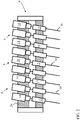
- EDM system 2 includes a guide structure 4, and a plurality of electrode devices 6 positioned at least partially within guide structure 4 (e.g., guide structure 4 at least partially envelops electrode devices 6).
- electrode devices 6 are aligned to provide an electrical discharge to a workpiece 8 (e.g., a turbine component such as a gas turbine airfoil).
- Each of the plurality of electrode devices 6 includes an electrode 10 for positioning proximate (e.g., contacting or nominally separated from) workpiece 8, and an electrode holder 12 coupled to electrode 10 for holding the electrode 10 proximate workpiece 8.
- Each electrode device 6 further includes a driver 14 coupled to electrode holder 12.
- Driver 14 is adapted to modify a position of electrode 10 (relative to workpiece 8), held inside holder 12, with linear bearings.
- driver 14 can include at least one of an electric or pneumatic driver, and in some cases, can include a voice coil or a hydraulic driver.
- EDM system 2 further includes a control system (CS) 18 operably connected with driver 14 (e.g., via conventional wireless and/or hard-wired means), where control system 18 is configured to provide instructions to the driver 14 of at least one of the plurality of electrode devices 6 to modify a position (and consequently, the workpiece-electrode gap 11) of the at least one of the plurality of electrodes 10 independently of at least one other one of the plurality of electrodes 10 based upon the detected position (and, e.g., workpiece-electrode gap 11) of the electrode 10.
- CS control system
- control system 18 may monitor the position of one or more electrodes 10 as well as gap 11 between each electrode 10 and workpiece 8 (e.g., relative to a prescribed pattern and/or predetermined positional information and gap distance, via sensor(s) 16), comparing data about the topography of workpiece 8, along with desired hole locations, depths, etc. with data obtained from sensor(s) 16), and provide operating instructions to electrode device(s) 6 to independently modify a position (and consequently, gap 11) of at least one of the electrodes 10 in those device(s) 6.
- control system 18 may send operating instructions to halt driver 14 of one electrode device 6 under certain operating conditions (e.g., where sensor(s) 16 detect that electrode 10 has reached its desired depth of penetration into workpiece 8).
- Each electrode 10 is controlled independently according to its position and gap 11 between the tip of electrode 10 and workpiece 8 (e.g., opening in workpiece 8 to be formed). As noted herein, electrode 10 is driven (e.g., via driver 14) toward workpiece 8. Once electrode 10 starts to discharge on workpiece 8, electrode 10 federate can slow down and CS 18 takes over the feed control. If gap 11 becomes too small with a too low a voltage signal, the feed rate is slowed down (or even reversed) for electrode withdrawal to avoid shorting and overheating to workpiece 8. Once senor(s) 16 detect the end depth for the process (e.g., hole is formed to desired depth), the CS 18 stops feeding electrode 10 and withdraws electrode 10 independently while other electrodes 10 may still feed, or may be withdrawn, independently.
- guide structure 4 is coupled to electrode holder 12, where guide structure 4 includes a slide bearing 20 ( FIG. 4 , FIG. 5 ) allowing electrode holder 12 to move relative to guide structure 4.
- EDM system 2 can further include a machine ram 22 coupled to guide structure 4, and a back plate 24 coupled to guide structure 4, where back plate 24 at least partially supports the driver 14 in each of the plurality of electrode devices 6.
- all of the plurality of electrode devices 6 can be aligned parallel with respect to one another and uniformly angled with respect to the guide structure 4. That is, all electrode devices 6 can be aligned in a parallel arrangement in order to form equally spaced openings in workpiece 8, at a same angle of contact.
- each of the plurality of electrode devices 6 is connected with an independent power supply (IPS) 26, such that a loss of power to one of the plurality of electrode devices 6 does not cause a loss of power to the remainder of the electrode devices 6.
- IPS independent power supply
- multiple power supplies 26 are employed, such that the entirety of electrode devices 6 is not reliant upon a single power source.
- IPS 26 can prevent issues with a consolidated, central power supply, utilized in conventional systems. That is, a shared power supply provides one large spark to one of the multiple electrodes.
- the independent and dedicated power supplies deliver precise amounts of power to one electrode at a desired time, based upon local gap control, as described herein. With a small gap and fast feeding, the independent power supply systems according to various embodiments can provide higher power locally when compared with conventional approaches.
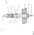
- FIG. 4 shows a close-up partial cross-sectional view of a portion of an electrode device 6 not according to the invention.
- electrode device 6 is positioned within back plate 24 and slide bearing 20, where slide bearing 20 is housed within a guide plate 28.
- Driver 14 can include a hydraulic cylinder 30 and a piston 32 within that hydraulic cylinder 30 ( FIG. 4 ). Both the cylinder 30 and piston 32 can be held within a bushing 34 at least partially retained by back plate 24.
- Driver 14 can be coupled to electrode holder 12 by an insulator connector 36.
- electrode 10 is held by a clamp (e.g., collet clamp) 38 at the tip of electrode holder 12.
- FIG. 5 shows an additional close-up partial cross-sectional view of a portion of an electrode device 6, where driver 14 includes a rotating tube electrode device 40, according to the invention.
- the rotating tube electrode device 14 is coupled to a hydraulic piston 32 (connected with a cylinder 30) as shown and described with reference to FIG. 4 .
- rotating tube electrode device 40 can further include a pneumatic rotary driver 42 including an air motor 44 (having compressed air inlet 46 and outlet 48), a water inlet 50 upstream of the air motor 44 (with adjacent seal 52), and a rotor 54 coupled with the air motor 44 (where rotor 54 is supported on bearings 56).
- Rotor 54 is connected with an electrode holder 12 (including electrode clamp 38).
- rotating tube electrode 40 is configured to rotate electrode 10 while hydraulic piston 32 drives electrode 10 toward workpiece 8.
- This rotating tube electrode device 40 shown in FIG. 5 can be useful in forming holes in workpiece 8 in spaces requiring minimal clearance and/or a high density of electrode devices 6.
Landscapes
- Engineering & Computer Science (AREA)
- Mechanical Engineering (AREA)
- Physics & Mathematics (AREA)
- Thermal Sciences (AREA)
- Manufacturing & Machinery (AREA)
- Electrical Discharge Machining, Electrochemical Machining, And Combined Machining (AREA)
- Turbine Rotor Nozzle Sealing (AREA)
Claims (8)
- Funkenerosionsbearbeitungssystem (electric discharge machining, EDM-System) (2), umfassend:eine Führungsstruktur (4);eine Vielzahl von Elektrodenvorrichtungen (6), die zumindest teilweise innerhalb der Führungsstruktur (4) positioniert sind, wobei die Vielzahl von Elektrodenvorrichtungen (6) ausgerichtet ist, um eine Vielzahl von elektrischen Entladungen an einem Werkstück (8) bereitzustellen, wobei jede der Vielzahl von Elektrodenvorrichtungen (6) Folgendes einschließt:eine Elektrode (10) zum Positionieren in der Nähe des Werkstücks (8);einen Elektrodenhalter (12), der mit der Elektrode (10) gekoppelt ist, um die Elektrode (10) in der Nähe des Werkstücks (8) zu halten; undeinen Treiber (14), der mit dem Elektrodenhalter (12) gekoppelt ist, wobei der Treiber (14) angepasst ist, um eine Position des Elektrodenhalters (12) und der Elektrode (10) zu ändern,wobei der Treiber (14) eine Vorrichtung zum Drehen der Elektrode umfasst;ein Steuerungssystem (18), das betriebsfähig mit dem Treiber (14) verbunden ist, wobei das Steuerungssystem (18) konfiguriert ist, um Anweisungen an den Treiber (14) mindestens einer der Vielzahl von Elektrodenvorrichtungen (6) bereitzustellen, um eine Position der mindestens einen der Vielzahl von Elektroden (10) unabhängig von mindestens einer anderen der Vielzahl von Elektroden (10) zu ändern; wobeijede der Vielzahl von Elektrodenvorrichtungen (6) mit einer unabhängigen Stromversorgung (26) verbunden ist, so dass ein Stromverlust zu einer der Vielzahl von Elektrodenvorrichtungen (6) keinen Stromverlust zu einem Rest der Vielzahl von Elektrodenvorrichtungen (6) verursacht; dadurch gekennzeichnet, dassder Treiber (14) jeder der Vielzahl von Elektrodenvorrichtungen (6) eine rotierende Röhrenelektrodenvorrichtung (40) und einen Hydraulikkolben (32) umfasst, wobei die rotierende Röhrenelektrodenvorrichtung (40) mit dem Hydraulikkolben (32) gekoppelt ist und wobei die rotierende Röhrenelektrodenvorrichtung (40) konfiguriert ist, um die Elektrode (10) zu drehen, während der Hydraulikkolben (32) die Elektrode (10) in Richtung des Werkstücks (8) antreibt.
- System nach Anspruch 1, wobei die Führungsstruktur (4) mit dem Elektrodenhalter (12) gekoppelt ist, wobei die Führungsstruktur (4) ein Gleitlager (20) einschließt, das es dem Elektrodenhalter (12) ermöglicht, sich relativ zu der Führungsstruktur (4) zu bewegen.
- System nach einem der vorstehenden Ansprüche, ferner umfassend einen Maschinenstößel (22), der mit der Führungsstruktur (4) gekoppelt ist.
- System nach Anspruch 3, ferner umfassend eine Rückplatte (24), die mit der Führungsstruktur (4) gekoppelt ist, wobei die Rückplatte (24) den Treiber (14) zumindest teilweise in jeder der Vielzahl von Elektrodenvorrichtungen (6) stützt.
- System nach einem der vorstehenden Ansprüche, wobei alle der Vielzahl von Elektrodenvorrichtungen (6) parallel zueinander und gleichmäßig in Bezug auf die Führungsstruktur (4) abgewinkelt ausgerichtet sind.
- System nach einem der Ansprüche 1 bis 4, wobei eine erste der Vielzahl von Elektrodenvorrichtungen (6) in einem ersten Winkel in Bezug auf eine zweite der Vielzahl von Elektrodenvorrichtungen (6) ausgerichtet ist, und wobei eine dritte der Vielzahl von Elektrodenvorrichtungen (6) in einem zweiten Winkel in Bezug auf die zweite der Vielzahl von Elektrodenvorrichtungen (6) ausgerichtet ist, wobei der zweite Winkel sich von dem ersten Winkel unterscheidet.
- Funkenerosionsbearbeitungssystem (EDM-System) (2), nach Anspruch 1, ferner umfassend:mindestens einen Sensor (16) zum Erfassen einer Position einer Elektrode (10) relativ zu dem Werkstück (8) in der Vielzahl von Elektrodenvorrichtungen (6);wobei das Steuerungssystem (18) konfiguriert ist, um dem Treiber (14) Anweisungen von mindestens einer der Vielzahl von Elektrodenvorrichtungen (6) bereitzustellen, um eine Position der mindestens einen der Vielzahl von Elektroden (10) unabhängig von mindestens einer anderen der Vielzahl von Elektroden (10) basierend auf der erfassten Position der Elektrode (10) zu ändern.
- Funkenerosionsbearbeitungssystem (EDM-System) (2) nach Anspruch 7, ferner umfassend:einen Maschinenstößel (22), der mit der Führungsstruktur (4) gekoppelt ist; undeinen Satz unabhängiger Stromversorgungen (26), die mit jeder der Vielzahl von Elektrodenvorrichtungen (6) verbunden sind, so dass ein Stromverlust zu einer der Vielzahl von Elektrodenvorrichtungen (6) keinen Stromverlust zu einem Rest der Vielzahl von Elektrodenvorrichtungen (6) verursacht.
Applications Claiming Priority (1)
| Application Number | Priority Date | Filing Date | Title |
|---|---|---|---|
| US14/854,476 US9849528B2 (en) | 2015-09-15 | 2015-09-15 | Electrical discharge machining system having independent electrodes |
Publications (2)
| Publication Number | Publication Date |
|---|---|
| EP3144089A1 EP3144089A1 (de) | 2017-03-22 |
| EP3144089B1 true EP3144089B1 (de) | 2023-01-25 |
Family
ID=56683800
Family Applications (1)
| Application Number | Title | Priority Date | Filing Date |
|---|---|---|---|
| EP16183855.2A Active EP3144089B1 (de) | 2015-09-15 | 2016-08-11 | Funkenerosionsbearbeitungssystem mit unabhängigen elektroden |
Country Status (4)
| Country | Link |
|---|---|
| US (1) | US9849528B2 (de) |
| EP (1) | EP3144089B1 (de) |
| JP (1) | JP6997509B2 (de) |
| PL (1) | PL3144089T3 (de) |
Families Citing this family (6)
| Publication number | Priority date | Publication date | Assignee | Title |
|---|---|---|---|---|
| US10307846B2 (en) * | 2015-09-15 | 2019-06-04 | General Electric Company | Electrical discharge machining system having independent electrodes, related control system and method |
| US10589370B2 (en) * | 2017-05-08 | 2020-03-17 | General Electric Company | Automatic blocked hole identification |
| US10953483B2 (en) | 2017-11-15 | 2021-03-23 | General Electric Company | Tool electrode for and methods of electrical discharge machining |
| CN110385487B (zh) | 2018-04-19 | 2021-08-31 | 通用电气公司 | 电火花加工装置和方法 |
| CN110560801A (zh) * | 2019-08-28 | 2019-12-13 | 北京航星机器制造有限公司 | 一种舵面骨架穿丝孔的加工方法 |
| US12186820B2 (en) | 2021-01-06 | 2025-01-07 | General Electric Company | Contact matrix for grounding a ceramic component during electrical discharge machining |
Citations (4)
| Publication number | Priority date | Publication date | Assignee | Title |
|---|---|---|---|---|
| US4441004A (en) * | 1980-06-12 | 1984-04-03 | Inoue-Japax Research Incorporated | Multiple pipe element electrode assembly EDM method and apparatus |
| US6369343B1 (en) * | 2000-09-20 | 2002-04-09 | General Electric Company | Method and apparatus for electrical discharge machining |
| US6373018B1 (en) * | 2000-02-07 | 2002-04-16 | General Electric Company | Apparatus and method for electrical discharge machining multiple holes |
| US20110186551A1 (en) * | 2009-11-12 | 2011-08-04 | Denso Corporation | Electric discharge machine and method of producing nozzle body using the same |
Family Cites Families (29)
| Publication number | Priority date | Publication date | Assignee | Title |
|---|---|---|---|---|
| US679105A (en) | 1900-12-07 | 1901-07-23 | Henry Alonzo Buck | Piston for rotary engines. |
| US3590204A (en) * | 1968-05-16 | 1971-06-29 | Oconnor Thomas John | Structure for electroerosive machining with rotating tubular electrodes |
| JPS4815358B1 (de) * | 1969-08-27 | 1973-05-14 | ||
| US3740519A (en) * | 1972-03-27 | 1973-06-19 | Connor T O | Electrode for electro-erosion machining electrode |
| US4159407A (en) | 1974-03-23 | 1979-06-26 | Rolls-Royce (1971) Limited | Methods and apparatus for electrically machining a work piece |
| US4188522A (en) * | 1975-11-06 | 1980-02-12 | Amchem Company Limited | Method of machining a workpiece to a predetermined depth using a machining process in which machine tool wear occurs |
| GB1583442A (en) * | 1976-04-15 | 1981-01-28 | Rolls Royce | Method of and apparatus for controlling an electro-discharge drilling machine tool |
| JPS578038A (en) * | 1980-06-12 | 1982-01-16 | Inoue Japax Res Inc | Electrospark machining device |
| JPS5866629A (ja) | 1981-10-08 | 1983-04-20 | Inoue Japax Res Inc | 放電加工装置 |
| JPS60108213A (ja) * | 1983-11-17 | 1985-06-13 | Inoue Japax Res Inc | 放電加工用電極装置 |
| US4670635A (en) * | 1984-08-10 | 1987-06-02 | Ex-Cell-O Corporation | Multi-electrode electrical discharge machining apparatus |
| DE3447870A1 (de) * | 1984-12-31 | 1986-07-03 | Aktiengesellschaft für industrielle Elektronik AGIE Losone bei Locarno, Losone, Locarno | Verfahren und vorrichtung zur ermittlung der elektroerosiven fertigstellung eines startloches |
| US4814573A (en) * | 1986-04-07 | 1989-03-21 | Ex-Cell-O Corporation | Electrical discharge machining apparatus with exchangeable electrode refeed cartridge |
| US4819325A (en) | 1987-06-01 | 1989-04-11 | Technical Manufacturing Systems, Inc. | Method of forming electro-discharge machining electrode |
| GB8818586D0 (en) * | 1988-08-04 | 1988-09-07 | Transfer Technology Ltd | Working of electrically conductive materials by electrical erosion |
| GB8825064D0 (en) | 1988-10-26 | 1988-11-30 | Rolls Royce Plc | Combined edm & ultrasonic drilling |
| GB9014798D0 (en) * | 1990-07-04 | 1990-08-22 | Moss Machines Ltd | Method of refeeding electrical discharge machining electrodes |
| US5605639A (en) | 1993-12-21 | 1997-02-25 | United Technologies Corporation | Method of producing diffusion holes in turbine components by a multiple piece electrode |
| US5618450A (en) * | 1995-06-07 | 1997-04-08 | Stuart; James P. | Tool having interchangeable indicia marking electrodes for use in electrical discharge machining |
| JPH11170119A (ja) * | 1997-12-09 | 1999-06-29 | Hoden Seimitsu Kako Kenkyusho Ltd | 放電加工用電極保持装置 |
| US5983984A (en) | 1998-01-12 | 1999-11-16 | Ashland Inc. | Insulating sleeve compositions and their uses |
| US6165422A (en) * | 1999-03-01 | 2000-12-26 | Modern Hard Chrome Service Company | Apparatus for electric-discharge texturing of a roll |
| JP2000354914A (ja) * | 1999-06-16 | 2000-12-26 | Matsushita Electric Ind Co Ltd | 放電加工機 |
| US6403910B1 (en) | 1999-12-14 | 2002-06-11 | Hi-Tek Manufacturing, Inc. | EDM apparatus and method for performing EDM operation |
| US6831246B2 (en) | 2002-09-12 | 2004-12-14 | General Electric Company | Multi-station electrical discharge machining with single velocity command |
| DE102004044676A1 (de) * | 2004-09-09 | 2006-03-30 | Siemens Ag | Elektrodenanordnung mit veränderlicher Geometrie für elektrochemische Behandlungen |
| US8168913B2 (en) | 2009-05-28 | 2012-05-01 | General Electric Company | Electric discharge machining die sinking device |
| EP2881204B1 (de) | 2012-07-31 | 2018-09-26 | Makino Milling Machine Co., Ltd. | Austauschbestimmungsvorrichtung für eine funkenerosionsbearbeitungselektrode und austauschbestimmungsverfahren |
| US9452483B2 (en) | 2012-11-14 | 2016-09-27 | General Electric Company | Electric discharge machining die sinking device and related method of operation |
-
2015
- 2015-09-15 US US14/854,476 patent/US9849528B2/en active Active
-
2016
- 2016-08-11 EP EP16183855.2A patent/EP3144089B1/de active Active
- 2016-08-11 PL PL16183855.2T patent/PL3144089T3/pl unknown
- 2016-09-08 JP JP2016175113A patent/JP6997509B2/ja active Active
Patent Citations (4)
| Publication number | Priority date | Publication date | Assignee | Title |
|---|---|---|---|---|
| US4441004A (en) * | 1980-06-12 | 1984-04-03 | Inoue-Japax Research Incorporated | Multiple pipe element electrode assembly EDM method and apparatus |
| US6373018B1 (en) * | 2000-02-07 | 2002-04-16 | General Electric Company | Apparatus and method for electrical discharge machining multiple holes |
| US6369343B1 (en) * | 2000-09-20 | 2002-04-09 | General Electric Company | Method and apparatus for electrical discharge machining |
| US20110186551A1 (en) * | 2009-11-12 | 2011-08-04 | Denso Corporation | Electric discharge machine and method of producing nozzle body using the same |
Also Published As
| Publication number | Publication date |
|---|---|
| JP6997509B2 (ja) | 2022-01-17 |
| EP3144089A1 (de) | 2017-03-22 |
| US20170072487A1 (en) | 2017-03-16 |
| JP2017056550A (ja) | 2017-03-23 |
| PL3144089T3 (pl) | 2023-03-27 |
| US9849528B2 (en) | 2017-12-26 |
Similar Documents
| Publication | Publication Date | Title |
|---|---|---|
| US9849528B2 (en) | Electrical discharge machining system having independent electrodes | |
| US11161190B2 (en) | Electrode for electroerosion machining system | |
| EP1808253B1 (de) | Elektroerosive Duplexbearbeitung | |
| JP6855369B2 (ja) | 電気加工装置および方法 | |
| EP3486018B1 (de) | Verfahren und vorrichtung zum herstellen von formen mittels elektrischer bearbeitung | |
| US8710392B2 (en) | Electric discharge machining hole drilling | |
| US11717903B2 (en) | Electrical discharge machining device and method | |
| EP3144090B1 (de) | Funkenerosionssystem mit unabhängigen elektroden, zugehöriges steuerungssystem und -verfahren | |
| US20120187092A1 (en) | Electric discharge machining die sinking device | |
| EP2246139B1 (de) | Spannverfahren für Turbinenschaufel. | |
| CN100522439C (zh) | 用于在有限空间中加工的设备 | |
| CN106180925B (zh) | 用于在电腐蚀加工中材料再循环的方法 | |
| US7019245B2 (en) | Method and apparatus for erosion machining with an electrical contact element | |
| US6831246B2 (en) | Multi-station electrical discharge machining with single velocity command | |
| KR101843289B1 (ko) | 방전 가공기의 전극봉의 가이드 이탈을 확인할 수 있는 방법 및 장치 | |
| CN115780925B (zh) | 采用圆片电极高速旋转实现深窄缝电火花高效切割的方法 |
Legal Events
| Date | Code | Title | Description |
|---|---|---|---|
| PUAI | Public reference made under article 153(3) epc to a published international application that has entered the european phase |
Free format text: ORIGINAL CODE: 0009012 |
|
| STAA | Information on the status of an ep patent application or granted ep patent |
Free format text: STATUS: THE APPLICATION HAS BEEN PUBLISHED |
|
| AK | Designated contracting states |
Kind code of ref document: A1 Designated state(s): AL AT BE BG CH CY CZ DE DK EE ES FI FR GB GR HR HU IE IS IT LI LT LU LV MC MK MT NL NO PL PT RO RS SE SI SK SM TR |
|
| AX | Request for extension of the european patent |
Extension state: BA ME |
|
| STAA | Information on the status of an ep patent application or granted ep patent |
Free format text: STATUS: REQUEST FOR EXAMINATION WAS MADE |
|
| 17P | Request for examination filed |
Effective date: 20170922 |
|
| RBV | Designated contracting states (corrected) |
Designated state(s): AL AT BE BG CH CY CZ DE DK EE ES FI FR GB GR HR HU IE IS IT LI LT LU LV MC MK MT NL NO PL PT RO RS SE SI SK SM TR |
|
| TPAC | Observations filed by third parties |
Free format text: ORIGINAL CODE: EPIDOSNTIPA |
|
| STAA | Information on the status of an ep patent application or granted ep patent |
Free format text: STATUS: EXAMINATION IS IN PROGRESS |
|
| 17Q | First examination report despatched |
Effective date: 20200114 |
|
| GRAP | Despatch of communication of intention to grant a patent |
Free format text: ORIGINAL CODE: EPIDOSNIGR1 |
|
| STAA | Information on the status of an ep patent application or granted ep patent |
Free format text: STATUS: GRANT OF PATENT IS INTENDED |
|
| INTG | Intention to grant announced |
Effective date: 20221012 |
|
| GRAS | Grant fee paid |
Free format text: ORIGINAL CODE: EPIDOSNIGR3 |
|
| GRAA | (expected) grant |
Free format text: ORIGINAL CODE: 0009210 |
|
| STAA | Information on the status of an ep patent application or granted ep patent |
Free format text: STATUS: THE PATENT HAS BEEN GRANTED |
|
| AK | Designated contracting states |
Kind code of ref document: B1 Designated state(s): AL AT BE BG CH CY CZ DE DK EE ES FI FR GB GR HR HU IE IS IT LI LT LU LV MC MK MT NL NO PL PT RO RS SE SI SK SM TR |
|
| REG | Reference to a national code |
Ref country code: GB Ref legal event code: FG4D |
|
| REG | Reference to a national code |
Ref country code: CH Ref legal event code: EP |
|
| REG | Reference to a national code |
Ref country code: AT Ref legal event code: REF Ref document number: 1545595 Country of ref document: AT Kind code of ref document: T Effective date: 20230215 Ref country code: IE Ref legal event code: FG4D |
|
| REG | Reference to a national code |
Ref country code: DE Ref legal event code: R096 Ref document number: 602016077592 Country of ref document: DE |
|
| REG | Reference to a national code |
Ref country code: NL Ref legal event code: FP |
|
| REG | Reference to a national code |
Ref country code: LT Ref legal event code: MG9D |
|
| REG | Reference to a national code |
Ref country code: AT Ref legal event code: MK05 Ref document number: 1545595 Country of ref document: AT Kind code of ref document: T Effective date: 20230125 |
|
| PG25 | Lapsed in a contracting state [announced via postgrant information from national office to epo] |
Ref country code: RS Free format text: LAPSE BECAUSE OF FAILURE TO SUBMIT A TRANSLATION OF THE DESCRIPTION OR TO PAY THE FEE WITHIN THE PRESCRIBED TIME-LIMIT Effective date: 20230125 Ref country code: PT Free format text: LAPSE BECAUSE OF FAILURE TO SUBMIT A TRANSLATION OF THE DESCRIPTION OR TO PAY THE FEE WITHIN THE PRESCRIBED TIME-LIMIT Effective date: 20230525 Ref country code: NO Free format text: LAPSE BECAUSE OF FAILURE TO SUBMIT A TRANSLATION OF THE DESCRIPTION OR TO PAY THE FEE WITHIN THE PRESCRIBED TIME-LIMIT Effective date: 20230425 Ref country code: LV Free format text: LAPSE BECAUSE OF FAILURE TO SUBMIT A TRANSLATION OF THE DESCRIPTION OR TO PAY THE FEE WITHIN THE PRESCRIBED TIME-LIMIT Effective date: 20230125 Ref country code: LT Free format text: LAPSE BECAUSE OF FAILURE TO SUBMIT A TRANSLATION OF THE DESCRIPTION OR TO PAY THE FEE WITHIN THE PRESCRIBED TIME-LIMIT Effective date: 20230125 Ref country code: HR Free format text: LAPSE BECAUSE OF FAILURE TO SUBMIT A TRANSLATION OF THE DESCRIPTION OR TO PAY THE FEE WITHIN THE PRESCRIBED TIME-LIMIT Effective date: 20230125 Ref country code: ES Free format text: LAPSE BECAUSE OF FAILURE TO SUBMIT A TRANSLATION OF THE DESCRIPTION OR TO PAY THE FEE WITHIN THE PRESCRIBED TIME-LIMIT Effective date: 20230125 Ref country code: AT Free format text: LAPSE BECAUSE OF FAILURE TO SUBMIT A TRANSLATION OF THE DESCRIPTION OR TO PAY THE FEE WITHIN THE PRESCRIBED TIME-LIMIT Effective date: 20230125 |
|
| PG25 | Lapsed in a contracting state [announced via postgrant information from national office to epo] |
Ref country code: SE Free format text: LAPSE BECAUSE OF FAILURE TO SUBMIT A TRANSLATION OF THE DESCRIPTION OR TO PAY THE FEE WITHIN THE PRESCRIBED TIME-LIMIT Effective date: 20230125 Ref country code: IS Free format text: LAPSE BECAUSE OF FAILURE TO SUBMIT A TRANSLATION OF THE DESCRIPTION OR TO PAY THE FEE WITHIN THE PRESCRIBED TIME-LIMIT Effective date: 20230525 Ref country code: GR Free format text: LAPSE BECAUSE OF FAILURE TO SUBMIT A TRANSLATION OF THE DESCRIPTION OR TO PAY THE FEE WITHIN THE PRESCRIBED TIME-LIMIT Effective date: 20230426 Ref country code: FI Free format text: LAPSE BECAUSE OF FAILURE TO SUBMIT A TRANSLATION OF THE DESCRIPTION OR TO PAY THE FEE WITHIN THE PRESCRIBED TIME-LIMIT Effective date: 20230125 |
|
| REG | Reference to a national code |
Ref country code: DE Ref legal event code: R097 Ref document number: 602016077592 Country of ref document: DE |
|
| PG25 | Lapsed in a contracting state [announced via postgrant information from national office to epo] |
Ref country code: SM Free format text: LAPSE BECAUSE OF FAILURE TO SUBMIT A TRANSLATION OF THE DESCRIPTION OR TO PAY THE FEE WITHIN THE PRESCRIBED TIME-LIMIT Effective date: 20230125 Ref country code: RO Free format text: LAPSE BECAUSE OF FAILURE TO SUBMIT A TRANSLATION OF THE DESCRIPTION OR TO PAY THE FEE WITHIN THE PRESCRIBED TIME-LIMIT Effective date: 20230125 Ref country code: EE Free format text: LAPSE BECAUSE OF FAILURE TO SUBMIT A TRANSLATION OF THE DESCRIPTION OR TO PAY THE FEE WITHIN THE PRESCRIBED TIME-LIMIT Effective date: 20230125 Ref country code: DK Free format text: LAPSE BECAUSE OF FAILURE TO SUBMIT A TRANSLATION OF THE DESCRIPTION OR TO PAY THE FEE WITHIN THE PRESCRIBED TIME-LIMIT Effective date: 20230125 Ref country code: CZ Free format text: LAPSE BECAUSE OF FAILURE TO SUBMIT A TRANSLATION OF THE DESCRIPTION OR TO PAY THE FEE WITHIN THE PRESCRIBED TIME-LIMIT Effective date: 20230125 |
|
| REG | Reference to a national code |
Ref country code: DE Ref legal event code: R081 Ref document number: 602016077592 Country of ref document: DE Owner name: GENERAL ELECTRIC TECHNOLOGY GMBH, CH Free format text: FORMER OWNER: GENERAL ELECTRIC COMPANY, SCHENECTADY, NY, US |
|
| PG25 | Lapsed in a contracting state [announced via postgrant information from national office to epo] |
Ref country code: SK Free format text: LAPSE BECAUSE OF FAILURE TO SUBMIT A TRANSLATION OF THE DESCRIPTION OR TO PAY THE FEE WITHIN THE PRESCRIBED TIME-LIMIT Effective date: 20230125 |
|
| PLBE | No opposition filed within time limit |
Free format text: ORIGINAL CODE: 0009261 |
|
| STAA | Information on the status of an ep patent application or granted ep patent |
Free format text: STATUS: NO OPPOSITION FILED WITHIN TIME LIMIT |
|
| 26N | No opposition filed |
Effective date: 20231026 |
|
| PG25 | Lapsed in a contracting state [announced via postgrant information from national office to epo] |
Ref country code: SI Free format text: LAPSE BECAUSE OF FAILURE TO SUBMIT A TRANSLATION OF THE DESCRIPTION OR TO PAY THE FEE WITHIN THE PRESCRIBED TIME-LIMIT Effective date: 20230125 |
|
| PG25 | Lapsed in a contracting state [announced via postgrant information from national office to epo] |
Ref country code: MC Free format text: LAPSE BECAUSE OF FAILURE TO SUBMIT A TRANSLATION OF THE DESCRIPTION OR TO PAY THE FEE WITHIN THE PRESCRIBED TIME-LIMIT Effective date: 20230125 |
|
| REG | Reference to a national code |
Ref country code: GB Ref legal event code: 732E Free format text: REGISTERED BETWEEN 20240222 AND 20240228 |
|
| REG | Reference to a national code |
Ref country code: CH Ref legal event code: PL |
|
| PG25 | Lapsed in a contracting state [announced via postgrant information from national office to epo] |
Ref country code: MC Free format text: LAPSE BECAUSE OF FAILURE TO SUBMIT A TRANSLATION OF THE DESCRIPTION OR TO PAY THE FEE WITHIN THE PRESCRIBED TIME-LIMIT Effective date: 20230125 |
|
| PG25 | Lapsed in a contracting state [announced via postgrant information from national office to epo] |
Ref country code: LU Free format text: LAPSE BECAUSE OF NON-PAYMENT OF DUE FEES Effective date: 20230811 |
|
| REG | Reference to a national code |
Ref country code: NL Ref legal event code: PD Owner name: GENERAL ELECTRIC TECHNOLOGY GMBH; CH Free format text: DETAILS ASSIGNMENT: CHANGE OF OWNER(S), ASSIGNMENT; FORMER OWNER NAME: GENERAL ELECTRIC COMPANY Effective date: 20240410 |
|
| PG25 | Lapsed in a contracting state [announced via postgrant information from national office to epo] |
Ref country code: LU Free format text: LAPSE BECAUSE OF NON-PAYMENT OF DUE FEES Effective date: 20230811 Ref country code: CH Free format text: LAPSE BECAUSE OF NON-PAYMENT OF DUE FEES Effective date: 20230831 |
|
| REG | Reference to a national code |
Ref country code: BE Ref legal event code: MM Effective date: 20230831 |
|
| REG | Reference to a national code |
Ref country code: IE Ref legal event code: MM4A |
|
| PG25 | Lapsed in a contracting state [announced via postgrant information from national office to epo] |
Ref country code: IT Free format text: LAPSE BECAUSE OF FAILURE TO SUBMIT A TRANSLATION OF THE DESCRIPTION OR TO PAY THE FEE WITHIN THE PRESCRIBED TIME-LIMIT Effective date: 20230125 |
|
| PG25 | Lapsed in a contracting state [announced via postgrant information from national office to epo] |
Ref country code: IE Free format text: LAPSE BECAUSE OF NON-PAYMENT OF DUE FEES Effective date: 20230811 |
|
| PG25 | Lapsed in a contracting state [announced via postgrant information from national office to epo] |
Ref country code: IE Free format text: LAPSE BECAUSE OF NON-PAYMENT OF DUE FEES Effective date: 20230811 Ref country code: FR Free format text: LAPSE BECAUSE OF NON-PAYMENT OF DUE FEES Effective date: 20230831 |
|
| PG25 | Lapsed in a contracting state [announced via postgrant information from national office to epo] |
Ref country code: BE Free format text: LAPSE BECAUSE OF NON-PAYMENT OF DUE FEES Effective date: 20230831 |
|
| PG25 | Lapsed in a contracting state [announced via postgrant information from national office to epo] |
Ref country code: BG Free format text: LAPSE BECAUSE OF FAILURE TO SUBMIT A TRANSLATION OF THE DESCRIPTION OR TO PAY THE FEE WITHIN THE PRESCRIBED TIME-LIMIT Effective date: 20230125 |
|
| PG25 | Lapsed in a contracting state [announced via postgrant information from national office to epo] |
Ref country code: BG Free format text: LAPSE BECAUSE OF FAILURE TO SUBMIT A TRANSLATION OF THE DESCRIPTION OR TO PAY THE FEE WITHIN THE PRESCRIBED TIME-LIMIT Effective date: 20230125 |
|
| PG25 | Lapsed in a contracting state [announced via postgrant information from national office to epo] |
Ref country code: CY Free format text: LAPSE BECAUSE OF FAILURE TO SUBMIT A TRANSLATION OF THE DESCRIPTION OR TO PAY THE FEE WITHIN THE PRESCRIBED TIME-LIMIT; INVALID AB INITIO Effective date: 20160811 |
|
| PG25 | Lapsed in a contracting state [announced via postgrant information from national office to epo] |
Ref country code: HU Free format text: LAPSE BECAUSE OF FAILURE TO SUBMIT A TRANSLATION OF THE DESCRIPTION OR TO PAY THE FEE WITHIN THE PRESCRIBED TIME-LIMIT; INVALID AB INITIO Effective date: 20160811 |
|
| PGFP | Annual fee paid to national office [announced via postgrant information from national office to epo] |
Ref country code: NL Payment date: 20250723 Year of fee payment: 10 |
|
| PGFP | Annual fee paid to national office [announced via postgrant information from national office to epo] |
Ref country code: DE Payment date: 20250724 Year of fee payment: 10 |
|
| PGFP | Annual fee paid to national office [announced via postgrant information from national office to epo] |
Ref country code: PL Payment date: 20250723 Year of fee payment: 10 |
|
| PGFP | Annual fee paid to national office [announced via postgrant information from national office to epo] |
Ref country code: GB Payment date: 20250725 Year of fee payment: 10 |
|
| PG25 | Lapsed in a contracting state [announced via postgrant information from national office to epo] |
Ref country code: TR Free format text: LAPSE BECAUSE OF FAILURE TO SUBMIT A TRANSLATION OF THE DESCRIPTION OR TO PAY THE FEE WITHIN THE PRESCRIBED TIME-LIMIT Effective date: 20230125 |