EP3144090A1 - Funkenerosionssystem mit unabhängigen elektroden, zugehöriges steuerungssystem und -verfahren - Google Patents
Funkenerosionssystem mit unabhängigen elektroden, zugehöriges steuerungssystem und -verfahren Download PDFInfo
- Publication number
- EP3144090A1 EP3144090A1 EP16188463.0A EP16188463A EP3144090A1 EP 3144090 A1 EP3144090 A1 EP 3144090A1 EP 16188463 A EP16188463 A EP 16188463A EP 3144090 A1 EP3144090 A1 EP 3144090A1
- Authority
- EP
- European Patent Office
- Prior art keywords
- electrode
- workpiece
- electrodes
- devices
- electrode devices
- Prior art date
- Legal status (The legal status is an assumption and is not a legal conclusion. Google has not performed a legal analysis and makes no representation as to the accuracy of the status listed.)
- Granted
Links
Images


Classifications
-
- B—PERFORMING OPERATIONS; TRANSPORTING
- B23—MACHINE TOOLS; METAL-WORKING NOT OTHERWISE PROVIDED FOR
- B23H—WORKING OF METAL BY THE ACTION OF A HIGH CONCENTRATION OF ELECTRIC CURRENT ON A WORKPIECE USING AN ELECTRODE WHICH TAKES THE PLACE OF A TOOL; SUCH WORKING COMBINED WITH OTHER FORMS OF WORKING OF METAL
- B23H1/00—Electrical discharge machining, i.e. removing metal with a series of rapidly recurring electrical discharges between an electrode and a workpiece in the presence of a fluid dielectric
- B23H1/02—Electric circuits specially adapted therefor, e.g. power supply, control, preventing short circuits or other abnormal discharges
- B23H1/028—Electric circuits specially adapted therefor, e.g. power supply, control, preventing short circuits or other abnormal discharges for multiple gap machining
-
- B—PERFORMING OPERATIONS; TRANSPORTING
- B23—MACHINE TOOLS; METAL-WORKING NOT OTHERWISE PROVIDED FOR
- B23H—WORKING OF METAL BY THE ACTION OF A HIGH CONCENTRATION OF ELECTRIC CURRENT ON A WORKPIECE USING AN ELECTRODE WHICH TAKES THE PLACE OF A TOOL; SUCH WORKING COMBINED WITH OTHER FORMS OF WORKING OF METAL
- B23H1/00—Electrical discharge machining, i.e. removing metal with a series of rapidly recurring electrical discharges between an electrode and a workpiece in the presence of a fluid dielectric
- B23H1/04—Electrodes specially adapted therefor or their manufacture
-
- B—PERFORMING OPERATIONS; TRANSPORTING
- B23—MACHINE TOOLS; METAL-WORKING NOT OTHERWISE PROVIDED FOR
- B23H—WORKING OF METAL BY THE ACTION OF A HIGH CONCENTRATION OF ELECTRIC CURRENT ON A WORKPIECE USING AN ELECTRODE WHICH TAKES THE PLACE OF A TOOL; SUCH WORKING COMBINED WITH OTHER FORMS OF WORKING OF METAL
- B23H7/00—Processes or apparatus applicable to both electrical discharge machining and electrochemical machining
- B23H7/26—Apparatus for moving or positioning electrode relatively to workpiece; Mounting of electrode
- B23H7/265—Mounting of one or more thin electrodes
-
- B—PERFORMING OPERATIONS; TRANSPORTING
- B23—MACHINE TOOLS; METAL-WORKING NOT OTHERWISE PROVIDED FOR
- B23H—WORKING OF METAL BY THE ACTION OF A HIGH CONCENTRATION OF ELECTRIC CURRENT ON A WORKPIECE USING AN ELECTRODE WHICH TAKES THE PLACE OF A TOOL; SUCH WORKING COMBINED WITH OTHER FORMS OF WORKING OF METAL
- B23H9/00—Machining specially adapted for treating particular metal objects or for obtaining special effects or results on metal objects
- B23H9/10—Working turbine blades or nozzles
-
- B—PERFORMING OPERATIONS; TRANSPORTING
- B23—MACHINE TOOLS; METAL-WORKING NOT OTHERWISE PROVIDED FOR
- B23H—WORKING OF METAL BY THE ACTION OF A HIGH CONCENTRATION OF ELECTRIC CURRENT ON A WORKPIECE USING AN ELECTRODE WHICH TAKES THE PLACE OF A TOOL; SUCH WORKING COMBINED WITH OTHER FORMS OF WORKING OF METAL
- B23H9/00—Machining specially adapted for treating particular metal objects or for obtaining special effects or results on metal objects
- B23H9/14—Making holes
-
- B—PERFORMING OPERATIONS; TRANSPORTING
- B23—MACHINE TOOLS; METAL-WORKING NOT OTHERWISE PROVIDED FOR
- B23H—WORKING OF METAL BY THE ACTION OF A HIGH CONCENTRATION OF ELECTRIC CURRENT ON A WORKPIECE USING AN ELECTRODE WHICH TAKES THE PLACE OF A TOOL; SUCH WORKING COMBINED WITH OTHER FORMS OF WORKING OF METAL
- B23H7/00—Processes or apparatus applicable to both electrical discharge machining and electrochemical machining
- B23H7/26—Apparatus for moving or positioning electrode relatively to workpiece; Mounting of electrode
- B23H7/30—Moving electrode in the feed direction
Definitions
- the subject matter disclosed herein relates to electrical discharge machining. Specifically, the subject matter disclosed herein relates to systems and methods for performing electrical discharge machining in turbine components, e.g., gas turbine blades or buckets.
- EDM Electrical discharge machining
- EDM is the most reliable technology used to form cooling holes and fuel injection holes in turbine components (e.g., airfoils). As such, EDM is widely used to form these holes in turbine airfoils.
- EDM drilling is relatively slow, even when using a set of multiple electrodes.
- several EDM machines are typically employed at one time in order to meet production time requirements, which occupies a significant amount of floor space in a manufacturing facility.
- local debris drives the slowdown and withdrawal of not only one or more affected electrodes but also the entire group of electrodes including the unaffected electrodes.
- the entire group of electrodes feeds or withdraws together according to the worst case electrode (such as the electrode with the most debris buildup or shortest workpiece-electrode gap).
- the overall feed rate or machining productivity follows the lowest feed rate of the worst electrode with the most debris buildup or shortest gap at any given time.
- an EDM system includes: a guide structure; a plurality of electrode devices positioned at least partially within the guide structure, the plurality of electrode devices aligned to provide a plurality of electrical discharges to a workpiece, each of the plurality of electrode devices including: an electrode for positioning proximate the workpiece; an electrode holder coupled to the electrode for holding the electrode proximate the workpiece; and a driver coupled to the electrode holder, the driver adapted to modify a position of the electrode holder and the electrode; and a control system operably connected with the driver of each electrode holder, the control system configured to perform a process including: initiating a hole formation program for each of the plurality of electrode devices; determining whether at least one electrode has completed formation of a corresponding hole in the workpiece; and separating the at least one electrode from the workpiece in response to determining that the at least one electrode has completed formation of the corresponding hole.
- an EDM system includes: a guide structure; a plurality of electrode devices positioned at least partially within the guide structure, the plurality of electrode devices aligned to provide a plurality of electrical discharges to a workpiece, each of the plurality of electrode devices including: an electrode for positioning proximate the workpiece; an electrode holder coupled to the electrode for holding the electrode proximate the workpiece; and a driver coupled to the electrode holder, the driver adapted to modify a position of the electrode holder and the electrode; and a control system operably connected with the driver of each electrode holder, the control system configured to perform a process including: initiating a hole formation program for each of the plurality of electrode devices; determining whether at least one electrode has completed formation of a corresponding hole in the workpiece; and separating the at least one electrode from the workpiece in response to determining that the at least one electrode has completed formation of the corresponding hole.
- a second aspect of the disclosure includes a method including: positioning an electrical discharge machining (EDM) system proximate a workpiece, the EDM system having: a guide structure; a plurality of electrode devices positioned at least partially within the guide structure, the plurality of electrode devices aligned to provide a plurality of electrical discharges to the workpiece, each of the plurality of electrode devices including: an electrode for positioning proximate the workpiece; an electrode holder coupled to the electrode for holding the electrode proximate the workpiece; and a driver coupled to the electrode holder, the driver adapted to modify a position of the electrode holder and the electrode, initiating a hole formation program for each of the plurality of electrode devices; determining whether at least one electrode has completed formation of a corresponding hole in the workpiece; and separating the at least one electrode from the workpiece in response to determining that the at least one electrode has completed formation of the corresponding hole.
- EDM electrical discharge machining
- a third aspect of the disclosure includes a system having: a control system for controlling operation of an electrical discharge machining (EDM) system proximate a workpiece, the EDM system having: a guide structure; a plurality of electrode devices positioned at least partially within the guide structure, the plurality of electrode devices aligned to provide a plurality of electrical discharges to the workpiece, each of the plurality of electrode devices including: an electrode for positioning proximate the workpiece; an electrode holder coupled to the electrode for holding the electrode proximate the workpiece; and a driver coupled to the electrode holder, the driver adapted to modify a position of the electrode holder and the electrode, the control system configured to perform processes including: initiating a hole formation program for each of the plurality of electrode devices; determining whether at least one electrode has completed formation of a corresponding hole in the workpiece; and separating the at least one electrode from the workpiece in response to determining that the at least one electrode has completed formation of the corresponding hole.
- EDM electrical discharge machining
- the subject matter disclosed relates to electrical discharge machining. Specifically, the subject matter disclosed herein relates to systems and methods for performing electrical discharge machining in turbine components, e.g., gas turbine blades or buckets.
- various embodiments of the disclosure include an electrical discharge machining (EDM) system having a set of independent electrodes. That is, the EDM system includes a plurality of independently powered, and thus independently controlled, electrodes. These independent electrodes can be insulated from one another, and coupled with at least two distinct controllers (e.g., several distinct controllers).
- the system can further include independent (electrically isolated) processors to detect different gaps between the electrodes, and opto-couplers to connect the independent processors to a central processor while keeping noise low.
- the system can include a mounting frame, back plate and guiding plate to stabilize the electrodes.
- Various features of the disclosure can increase the speed of EDM on turbine components (e.g., airfoils) by several times (e.g., up to ten times).
- the "A" axis represents axial orientation (along the axis of the turbine rotor, omitted for clarity).
- the terms “axial” and/or “axially” refer to the relative position/direction of objects along axis A, which is substantially parallel with the axis of rotation of the turbomachine (in particular, the rotor section).
- the terms “radial” and/or “radially” refer to the relative position/direction of objects along axis (r), which is substantially perpendicular with axis A and intersects axis A at only one location.
- circumferential and/or “circumferentially” refer to the relative position/direction of objects along a circumference (c) which surrounds axis A but does not intersect the axis A at any location. It is further understood that common numbering between FIGURES can denote substantially identical components in the FIGURES.
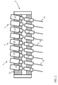
- EDM system 2 can include a guide structure 4, and a plurality of electrode devices 6 positioned at least partially within the guide structure 4 (e.g., guide structure 4 at least partially envelops electrode devices 6).
- electrode devices 6 are aligned to provide an electrical discharge to a workpiece 8 (e.g., a turbine component such as a gas turbine airfoil).
- Each of the plurality of electrode devices 6 can include an electrode 10 for positioning proximate (e.g., contacting or nominally separated from) workpiece 8, and an electrode holder 12 coupled to electrode 10 for holding the electrode 10 proximate workpiece 8.
- Each electrode device 6 can further include a driver 14 coupled to electrode holder 12.
- Driver 14 can be adapted to modify a position of electrode 10 (relative to workpiece 8), held inside holder 12, with linear bearings.
- driver 14 can include at least one of an electric or pneumatic driver, and in some cases, can include a voice coil or a hydraulic driver.
- EDM system 2 can further include at least one sensor 16 for detecting a position of an electrode 10 relative to a neighboring electrode 10 in the plurality of electrode devices 6.
- the at least one sensor 16 can include a plurality of sensors 16, and in some cases, at least one of sensor(s) 16 is configured to detect a position of multiple electrodes 10, as well as a workpiece-electrode gap 11 (distance between each electrode 10 and workpiece 8).
- the at least one sensor 16 can include, e.g., an optical sensor, laser-based sensor, or other conventional sensor capable of detecting the position of one or more electrodes 10.
- sensor(s ) 16 can include a gap sensor configured to detect the voltage signal between an electrode 10 and workpiece 8.
- EDM system 2 can further include a control system (CS) 18 operably connected with driver 14 (e.g., via conventional wireless and/or hard-wired means), where control system 18 is configured to provide instructions to the driver 14 of at least one of the plurality of electrode devices 6 to modify a position (and consequently, the workpiece-electrode gap 11) of the at least one of the plurality of electrodes 10 independently of at least one other one of the plurality of electrodes 10 based upon the detected position (and, e.g., workpiece-electrode gape 11) of the electrode 10.
- CS control system
- control system 18 is coupled to sensor(s) 16, and is configured to obtain data about the position of electrodes 10 (as well as gap 11 between each electrode 10 and workpiece 8) from sensor(s) 16, and based upon that position data (and data about gap 11), instruct driver 14 of at least one of electrode devices 6 to modify a position of its corresponding electrode 10 (and therefore modify gap 11 between each electrode 10 and workpiece 8).
- Control system 18 may be mechanically or electrically connected to electrode devices 6 (e.g., at driver 14) such that control system 18 may actuate at least one of electrode devices 6.
- Control system 18 may actuate driver 14 of electrode device(s) 6 in response to a detected position of electrode 10 (and gap 11 between each electrode 10 and workpiece 8), e.g., a discrepancy from a predicted electrode position (and gap 11 size), a discrepancy in position (and size of gap 11) with respect to guide structure 4, etc.
- Control system 18 may be a computerized, mechanical, or electro-mechanical device capable of actuating electrode devices 6 (e.g., by initiating or halting driver 14). In one embodiment control system 18 may be a computerized device capable of providing operating instructions to electrode devices 6.
- control system 18 may monitor the position of one or more electrodes 10 as well as gap 11 between each electrode 10 and workpiece 8 (e.g., relative to a prescribed pattern and/or predetermined positional information, via sensor(s) 16), comparing data about the topography of workpiece 8, along with desired hole locations, depths, etc. with data obtained from sensor(s) 16), and provide operating instructions to electrode device(s) 6 to independently modify a position (and consequently, gap 11) of at least one of the electrodes 10 in those device(s) 6. For example, control system 18 may send operating instructions to halt driver 14 of one electrode device 6 under certain operating conditions (e.g., where sensor(s) 16 detect that electrode 10 has reached its desired depth of penetration into workpiece 8).
- electrode device 6 may include electro-mechanical components, capable of receiving operating instructions (electrical signals) from control system 18 and producing mechanical motion (e.g., pausing, initiating, etc. driver 14).
- control system 18 may be an electro-mechanical device, capable of electrically monitoring (e.g., with sensors 16) parameters indicating positions of one or more electrodes 10 (and in some cases, gaps 11), and mechanically actuating the driver 14 of one or more corresponding electrode devices 6. While described in several embodiments herein, control system 18 may actuate electrode devices 6 through any other conventional means. In any case, the technical effect of control system 18 is to control operation of one or more electrode devices 6 as described herein.
- each electrode 10 is controlled independently according to its position and gap 11 between the tip of electrode 10 and workpiece 8 (e.g., opening in workpiece 8 to be formed).
- electrode 10 can be driven (e.g., via driver 14) toward workpiece 8.
- electrode 10 federate can slow down and CS 18 takes over the feed control. If gap 11 becomes too small with a too low a voltage signal, the feed rate is slowed down (or even reversed) for electrode withdrawal to avoid shorting and overheating to workpiece 8.
- the CS 18 stops feeding electrode 10 and withdraws electrode 10 independently while other electrodes 10 may still feed, or may be withdrawn, independently.
- guide structure 4 is coupled to electrode holder 12, where guide structure 4 includes a slide bearing 20 ( FIG. 4 , FIG. 5 ) allowing electrode holder 12 to move relative to guide structure 4.
- EDM system 2 can further include a machine ram 22 coupled to guide structure 4, and a back plate 24 coupled to guide structure 4, where back plate 24 at least partially supports the driver 14 in each of the plurality of electrode devices 6.
- all of the plurality of electrode devices 6 can be aligned parallel with respect to one another and uniformly angled with respect to the guide structure 4. That is, all electrode devices 6 can be aligned in a parallel arrangement in order to form equally spaced openings in workpiece 8, at a same angle of contact.
- FIG. 3 illustrates an alternative embodiment to the parallel arrangement in FIG. 2 , where electrode devices 6 are aligned in a multi-directional alignment.
- a first one (6a) of the plurality of electrode devices 6 is aligned at a first angle ( ⁇ 1) with respect to a second one (6b) of the plurality of electrode devices 6, and a third one (6c) of the plurality of electrode devices 6 is aligned at a second angle ( ⁇ 2) with respect to the second one 6b of the plurality of electrode devices 6, where the second angle ( ⁇ 2) is distinct from the first angle ( ⁇ 1).
- each of the plurality of electrode devices 6 is connected with an independent power supply (IPS) 26, such that a loss of power to one of the plurality of electrode devices 6 does not cause a loss of power to the remainder of the electrode devices 6.
- power supply 26 can be coupled to more than one electrode device 6, but it is understood that according to the embodiments disclosed herein, multiple power supplies 26 are employed, such that the entirety of electrode devices 6 is not reliant upon a single power source.
- IPS 26 can prevent issues with a consolidated, central power supply, utilized in conventional systems. That is, a shared power supply provides one large spark to one of the multiple electrodes.
- the independent and dedicated power supplies can delivers precise amounts of power to one electrode at a desired time, based upon local gap control, as described herein. With a small gap and fast feeding, the independent power supply systems according to various embodiments can provide higher power locally when compared with conventional approaches.
- each electrode-workpiece gap can differ (e.g., depending on local debris generation and dielectric flushing), independent and dedicated power supplies for distinct electrodes enables multiple sparks, for a high metal erosion rate, and a lower power level for high surface quality finishing after EDM is complete.
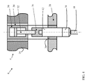
- FIG. 4 shows a close-up partial cross-sectional view of a portion of an electrode device 6 according to various embodiments.
- electrode device 6 is positioned within back plate 24 and slide bearing 20, where slide bearing 20 is housed within a guide plate 28.
- Driver 14 can include a hydraulic cylinder 30 and a piston 32 within that hydraulic cylinder 30 ( FIG. 4 ). Both the cylinder 30 and piston 32 can be held within a bushing 34 at least partially retained by back plate 24.
- Driver 14 can be coupled to electrode holder 12 by an insulator connector 36.
- electrode 10 is held by a clamp (e.g., collet clamp) 38 at the tip of electrode holder 12.
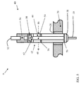
- FIG. 5 shows an additional close-up partial cross-sectional view of a portion of an electrode device 6, where driver 14 includes a rotating tube electrode device 40, according to various additional embodiments of the disclosure.
- rotating tube electrode device 14 is coupled to a hydraulic piston 32 (connected with a cylinder 30) as shown and described with reference to FIG. 4 .
- rotating tube electrode device 40 can further include a pneumatic rotary driver 42 including an air motor 44 (having compressed air inlet 46 and outlet 48), a water inlet 50 upstream of the air motor 44 (with adjacent seal 52), and a rotor 54 coupled with the air motor 44 (where rotor 54 is supported on bearings 56).
- Rotor 54 is connected with an electrode holder 12 (including electrode clamp 38).
- rotating tube electrode 40 is configured to rotate electrode 10 while hydraulic piston 32 drives electrode 10 toward workpiece 8.
- This rotating tube electrode device 40 shown in FIG. 5 can be useful in forming holes in workpiece 8 in spaces requiring minimal clearance and/or a high density of electrode devices 6.
- control system 18 described herein can be configured to perform control processes in order to enhance hole formation in a workpiece 8 relative to conventional approaches.
- utilizing independent power supplies 26 allows for a significant increase in the speed and control of hole formation in workpiece 8.
- the disclosed EDM system 2 includes a plurality of distinct, independent power supplies 26, which can create a plurality of sparks to increase the rate by which holes are formed in workpiece 8 relative to the conventional systems.
- EDM system 2 can be configured to independently spark distinct electrodes 6 based upon the location of those electrodes 6 relative to workpiece 8. For example, where a workpiece 8 includes a plurality of channels (e.g., fluid flow channels) to be formed at different depths and/or widths, independent control of electrodes 6 (including their corresponding power supplies 26) allows for formation of distinct hole types with the same EDM system 2, simultaneously. Further, the distributed, independent sparking mechanism in EDM system 2 can allow for formation of deep and/or small holes fast without the need for high voltage/high current sparks as required in conventional systems. Using lower voltages for sparking electrodes 6 can also enhance the lifespan of those electrodes 6, and improve efficiency by reducing down-time (due to decreased frequency of replacement/repair).
- channels e.g., fluid flow channels
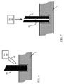
- EDM system 2 can include a fluid source (FS) 60 ( FIG. 1 ; FIG. 6 ) for flushing one or more electrodes 6.
- FIGS. 6-7 show distinct schematic configurations for flushing an electrode 6 according to various embodiments. Side flushing is illustrated in FIG. 6 , where a flushing fluid is introduced to an external surface of electrode 6 from a side region 62, via a nozzle 64.
- FIG. 7 shows another embodiment, where a flushing fluid is introduced through the body of electrode 6 in an internal flushing chamber 66.
- EDM system 2 can be configured to pulse electrodes 6, either during flushing or otherwise, to increase drilling efficiency and rate.
- pulsing of at least one of electrodes 6 is initiated when an overall feed rate slows, e.g., due to debris and/or carbon buildup.
- Pulsing of at least one of electrodes 6 can also be initiated when a percentage of shorting and/or arcing pulses exceeds a threshold level, e.g., 20%-30% of pulses.
- the discharge voltage of arcing and/or shorting pulses is lower than the voltage of normal discharge pulses. Also arcing and/or shorting pulses do not have the radio frequency signal for normal discharge pulses. These differences in electrical signal can be used to detect arcing and/or shorting pulses.
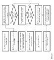
- FIG. 8 shows a flow diagram illustrating a method including processes according to various embodiments. Simultaneous reference is made to FIGS. 1-7 .
- a method of forming a set of holes in a workpiece 8, utilizing EDM system 2 can include:
- Process P9 includes: Raise the at least one electrode 6 and halt sparking in the at least one electrode 6.
- Process P10 includes: Raise ram 22 to heightened (home) position (ready for new workpiece 8).
- the method may be repeated (from process P2) for subsequent workpieces 8.
- FIG. 9 shows a control flow diagram 90 depicting control processes performed by control system 18, for controlling operation of EDM system 2 according to various embodiments.
- control system 18 uses a gap reference signal 92 as an input, and a feedforward processor 94 converts that signal 92 into a reference feed rate 96 at normal discharge conditions (when maximum electrode pulses are equal to normal discharge pulses).
- the feedforward processor 94 is proportional with a gain factor, which can be set according to hole drilling depth, flushing conditions and/or power pulse parameters (e.g., on-time, off-time, voltage, and discharge current, etc.).
- the gain factor of feedforward processor 94 can be determined by an operator, or through a real-time iterative process by control system 18, and may be associated with a particular drilling depth of one or more holes to be formed by electrode(s) 6.
- Gap reference signal 92 may consist of a gap reference voltage, or in some cases, contain three target percentages of different electrical pulses (i.e., open pulses, erosion pulses and arcing/shorting pulses). The target percentage of arcing or shorting pulses will be equal to zero. A higher target percentage for open pulses, and lower target percentage for erosion pulses, drives the process to a larger discharge gap 98 for improved dielectric flushing.
- Gap reference signal 92 can be established based upon prior-run computer modeling or prior-run physical drilling examples.
- feedback processor 100 can detect different pulses and convert those pulses to a percentage.
- the difference between the feedback signal and reference signal is used in part as a driving signal for proportional-integral-derivative (PID) (also referred to as a feed rate controller) 102.
- PID proportional-integral-derivative
- Equation 1 F is a feedback signal, R is a reference signal, A is a scaling factor greater than 1, N ob is the percentage of feedback open pulses, Nor is the percentage reference open pulses, N eb is the percentage of feedback erosion pulses, and N er is the percentage of reference erosion pulses. With the percentage of reference arcing/shorting pulses being zero, N ab represents the percentage of feedback arcing/shorting pulses. B is the other scaling factor greater than one.
Landscapes
- Engineering & Computer Science (AREA)
- Mechanical Engineering (AREA)
- Physics & Mathematics (AREA)
- Thermal Sciences (AREA)
- Chemical & Material Sciences (AREA)
- Chemical Kinetics & Catalysis (AREA)
- Electrochemistry (AREA)
- Manufacturing & Machinery (AREA)
- Electrical Discharge Machining, Electrochemical Machining, And Combined Machining (AREA)
Applications Claiming Priority (1)
| Application Number | Priority Date | Filing Date | Title |
|---|---|---|---|
| US14/854,484 US10307846B2 (en) | 2015-09-15 | 2015-09-15 | Electrical discharge machining system having independent electrodes, related control system and method |
Publications (2)
| Publication Number | Publication Date |
|---|---|
| EP3144090A1 true EP3144090A1 (de) | 2017-03-22 |
| EP3144090B1 EP3144090B1 (de) | 2021-11-24 |
Family
ID=56920608
Family Applications (1)
| Application Number | Title | Priority Date | Filing Date |
|---|---|---|---|
| EP16188463.0A Not-in-force EP3144090B1 (de) | 2015-09-15 | 2016-09-13 | Funkenerosionssystem mit unabhängigen elektroden, zugehöriges steuerungssystem und -verfahren |
Country Status (3)
| Country | Link |
|---|---|
| US (1) | US10307846B2 (de) |
| EP (1) | EP3144090B1 (de) |
| JP (1) | JP6948773B2 (de) |
Families Citing this family (4)
| Publication number | Priority date | Publication date | Assignee | Title |
|---|---|---|---|---|
| US10589370B2 (en) * | 2017-05-08 | 2020-03-17 | General Electric Company | Automatic blocked hole identification |
| KR102329914B1 (ko) * | 2017-09-05 | 2021-11-23 | 한화에어로스페이스 주식회사 | 부품의 홀 가공 방법 |
| US10953483B2 (en) * | 2017-11-15 | 2021-03-23 | General Electric Company | Tool electrode for and methods of electrical discharge machining |
| WO2024102159A1 (en) * | 2022-11-10 | 2024-05-16 | General Electric Technology Gmbh | Ultrasonic measurement of electrode depth while electrical discharge machining |
Citations (4)
| Publication number | Priority date | Publication date | Assignee | Title |
|---|---|---|---|---|
| US4159407A (en) * | 1974-03-23 | 1979-06-26 | Rolls-Royce (1971) Limited | Methods and apparatus for electrically machining a work piece |
| US6403910B1 (en) * | 1999-12-14 | 2002-06-11 | Hi-Tek Manufacturing, Inc. | EDM apparatus and method for performing EDM operation |
| US20040050821A1 (en) * | 2002-09-12 | 2004-03-18 | General Electric Company | Multi-station electrical discharge machining with single velocity command |
| EP2881204A1 (de) * | 2012-07-31 | 2015-06-10 | Makino Milling Machine Co., Ltd. | Austauschbestimmungsvorrichtung für eine funkenerosionsbearbeitungselektrode und austauschbestimmungsverfahren |
Family Cites Families (29)
| Publication number | Priority date | Publication date | Assignee | Title |
|---|---|---|---|---|
| US679105A (en) | 1900-12-07 | 1901-07-23 | Henry Alonzo Buck | Piston for rotary engines. |
| US3740519A (en) | 1972-03-27 | 1973-06-19 | Connor T O | Electrode for electro-erosion machining electrode |
| US4044216A (en) * | 1976-02-27 | 1977-08-23 | Raycon Corporation | Multiple electrode electrical discharge machining |
| GB1583442A (en) * | 1976-04-15 | 1981-01-28 | Rolls Royce | Method of and apparatus for controlling an electro-discharge drilling machine tool |
| JPS5866629A (ja) * | 1981-10-08 | 1983-04-20 | Inoue Japax Res Inc | 放電加工装置 |
| US4510365A (en) * | 1982-05-06 | 1985-04-09 | Raycon Corporation | Electronic depth controller for EDM apparatus |
| EP0125812B1 (de) * | 1983-04-22 | 1986-12-30 | Inoue-Japax Research Incorporated | Bearbeitungszentrum |
| JPS60108213A (ja) | 1983-11-17 | 1985-06-13 | Inoue Japax Res Inc | 放電加工用電極装置 |
| DE3447870A1 (de) | 1984-12-31 | 1986-07-03 | Aktiengesellschaft für industrielle Elektronik AGIE Losone bei Locarno, Losone, Locarno | Verfahren und vorrichtung zur ermittlung der elektroerosiven fertigstellung eines startloches |
| US4814573A (en) | 1986-04-07 | 1989-03-21 | Ex-Cell-O Corporation | Electrical discharge machining apparatus with exchangeable electrode refeed cartridge |
| US4819325A (en) | 1987-06-01 | 1989-04-11 | Technical Manufacturing Systems, Inc. | Method of forming electro-discharge machining electrode |
| GB8818586D0 (en) * | 1988-08-04 | 1988-09-07 | Transfer Technology Ltd | Working of electrically conductive materials by electrical erosion |
| GB8825064D0 (en) | 1988-10-26 | 1988-11-30 | Rolls Royce Plc | Combined edm & ultrasonic drilling |
| GB9014798D0 (en) | 1990-07-04 | 1990-08-22 | Moss Machines Ltd | Method of refeeding electrical discharge machining electrodes |
| US5605639A (en) | 1993-12-21 | 1997-02-25 | United Technologies Corporation | Method of producing diffusion holes in turbine components by a multiple piece electrode |
| US5618450A (en) | 1995-06-07 | 1997-04-08 | Stuart; James P. | Tool having interchangeable indicia marking electrodes for use in electrical discharge machining |
| JPH11170119A (ja) | 1997-12-09 | 1999-06-29 | Hoden Seimitsu Kako Kenkyusho Ltd | 放電加工用電極保持装置 |
| US5983984A (en) | 1998-01-12 | 1999-11-16 | Ashland Inc. | Insulating sleeve compositions and their uses |
| US6165422A (en) | 1999-03-01 | 2000-12-26 | Modern Hard Chrome Service Company | Apparatus for electric-discharge texturing of a roll |
| JP2000354914A (ja) | 1999-06-16 | 2000-12-26 | Matsushita Electric Ind Co Ltd | 放電加工機 |
| US6723942B1 (en) * | 2003-03-06 | 2004-04-20 | Industrial Technology Research Institute | Automatic breakthrough detection device |
| US7378611B2 (en) * | 2004-03-19 | 2008-05-27 | General Electric Company | Apparatus and method for electrical discharge machining |
| DE102004044676A1 (de) | 2004-09-09 | 2006-03-30 | Siemens Ag | Elektrodenanordnung mit veränderlicher Geometrie für elektrochemische Behandlungen |
| KR100564160B1 (ko) * | 2005-01-21 | 2006-03-27 | 임창영 | 방전가공형 드릴장치의 가공전극 소모량 자동 측정방법 |
| DE112009001764B4 (de) * | 2008-07-24 | 2023-01-19 | Mitsubishi Electric Corporation | Funkenerosionsvorrichtung, Funkenerosionsverfahren und Verfahren zur Herstellung eines Halbleitersubstrats |
| US8168913B2 (en) | 2009-05-28 | 2012-05-01 | General Electric Company | Electric discharge machining die sinking device |
| US8525064B2 (en) | 2009-11-12 | 2013-09-03 | Denso Corporation | Electric discharge machine and method of producing nozzle body using the same |
| US9452483B2 (en) | 2012-11-14 | 2016-09-27 | General Electric Company | Electric discharge machining die sinking device and related method of operation |
| US9849528B2 (en) * | 2015-09-15 | 2017-12-26 | General Electric Company | Electrical discharge machining system having independent electrodes |
-
2015
- 2015-09-15 US US14/854,484 patent/US10307846B2/en not_active Expired - Fee Related
-
2016
- 2016-09-01 JP JP2016170416A patent/JP6948773B2/ja not_active Expired - Fee Related
- 2016-09-13 EP EP16188463.0A patent/EP3144090B1/de not_active Not-in-force
Patent Citations (4)
| Publication number | Priority date | Publication date | Assignee | Title |
|---|---|---|---|---|
| US4159407A (en) * | 1974-03-23 | 1979-06-26 | Rolls-Royce (1971) Limited | Methods and apparatus for electrically machining a work piece |
| US6403910B1 (en) * | 1999-12-14 | 2002-06-11 | Hi-Tek Manufacturing, Inc. | EDM apparatus and method for performing EDM operation |
| US20040050821A1 (en) * | 2002-09-12 | 2004-03-18 | General Electric Company | Multi-station electrical discharge machining with single velocity command |
| EP2881204A1 (de) * | 2012-07-31 | 2015-06-10 | Makino Milling Machine Co., Ltd. | Austauschbestimmungsvorrichtung für eine funkenerosionsbearbeitungselektrode und austauschbestimmungsverfahren |
Also Published As
| Publication number | Publication date |
|---|---|
| US20170072488A1 (en) | 2017-03-16 |
| JP6948773B2 (ja) | 2021-10-13 |
| EP3144090B1 (de) | 2021-11-24 |
| US10307846B2 (en) | 2019-06-04 |
| JP2017056547A (ja) | 2017-03-23 |
Similar Documents
| Publication | Publication Date | Title |
|---|---|---|
| EP3144089B1 (de) | Funkenerosionsbearbeitungssystem mit unabhängigen elektroden | |
| US11161190B2 (en) | Electrode for electroerosion machining system | |
| US8710392B2 (en) | Electric discharge machining hole drilling | |
| CN110227867B (zh) | 用于使用电加工来加工形状的方法及装置 | |
| EP3144090B1 (de) | Funkenerosionssystem mit unabhängigen elektroden, zugehöriges steuerungssystem und -verfahren | |
| US8168913B2 (en) | Electric discharge machining die sinking device | |
| US20130248495A1 (en) | Electrical discharge machining | |
| JP6855369B2 (ja) | 電気加工装置および方法 | |
| EP2246139B1 (de) | Spannverfahren für Turbinenschaufel. | |
| CN106180925B (zh) | 用于在电腐蚀加工中材料再循环的方法 | |
| EP3556502A1 (de) | Funkenerosionsvorrichtung und -verfahren | |
| JP2005118990A (ja) | 限られたスペースにおいて加工する装置及び方法 | |
| US7019245B2 (en) | Method and apparatus for erosion machining with an electrical contact element | |
| JP4559718B2 (ja) | 単一の速度コマンドを用いるマルチステーション放電加工 | |
| JP2022520555A (ja) | 導電性材料製部品の穿孔方法 | |
| GB2409041A (en) | EDM apparatus for detection of blockages |
Legal Events
| Date | Code | Title | Description |
|---|---|---|---|
| PUAI | Public reference made under article 153(3) epc to a published international application that has entered the european phase |
Free format text: ORIGINAL CODE: 0009012 |
|
| STAA | Information on the status of an ep patent application or granted ep patent |
Free format text: STATUS: THE APPLICATION HAS BEEN PUBLISHED |
|
| AK | Designated contracting states |
Kind code of ref document: A1 Designated state(s): AL AT BE BG CH CY CZ DE DK EE ES FI FR GB GR HR HU IE IS IT LI LT LU LV MC MK MT NL NO PL PT RO RS SE SI SK SM TR |
|
| AX | Request for extension of the european patent |
Extension state: BA ME |
|
| STAA | Information on the status of an ep patent application or granted ep patent |
Free format text: STATUS: REQUEST FOR EXAMINATION WAS MADE |
|
| 17P | Request for examination filed |
Effective date: 20170922 |
|
| RBV | Designated contracting states (corrected) |
Designated state(s): AL AT BE BG CH CY CZ DE DK EE ES FI FR GB GR HR HU IE IS IT LI LT LU LV MC MK MT NL NO PL PT RO RS SE SI SK SM TR |
|
| STAA | Information on the status of an ep patent application or granted ep patent |
Free format text: STATUS: EXAMINATION IS IN PROGRESS |
|
| 17Q | First examination report despatched |
Effective date: 20200206 |
|
| RIC1 | Information provided on ipc code assigned before grant |
Ipc: B23H 1/02 20060101AFI20210428BHEP Ipc: B23H 7/26 20060101ALI20210428BHEP Ipc: B23H 9/10 20060101ALI20210428BHEP Ipc: B23H 9/14 20060101ALI20210428BHEP Ipc: B23H 7/30 20060101ALN20210428BHEP |
|
| RIC1 | Information provided on ipc code assigned before grant |
Ipc: B23H 1/02 20060101AFI20210518BHEP Ipc: B23H 7/26 20060101ALI20210518BHEP Ipc: B23H 9/10 20060101ALI20210518BHEP Ipc: B23H 9/14 20060101ALI20210518BHEP Ipc: B23H 7/30 20060101ALN20210518BHEP |
|
| GRAP | Despatch of communication of intention to grant a patent |
Free format text: ORIGINAL CODE: EPIDOSNIGR1 |
|
| STAA | Information on the status of an ep patent application or granted ep patent |
Free format text: STATUS: GRANT OF PATENT IS INTENDED |
|
| INTG | Intention to grant announced |
Effective date: 20210701 |
|
| GRAS | Grant fee paid |
Free format text: ORIGINAL CODE: EPIDOSNIGR3 |
|
| GRAA | (expected) grant |
Free format text: ORIGINAL CODE: 0009210 |
|
| STAA | Information on the status of an ep patent application or granted ep patent |
Free format text: STATUS: THE PATENT HAS BEEN GRANTED |
|
| AK | Designated contracting states |
Kind code of ref document: B1 Designated state(s): AL AT BE BG CH CY CZ DE DK EE ES FI FR GB GR HR HU IE IS IT LI LT LU LV MC MK MT NL NO PL PT RO RS SE SI SK SM TR |
|
| REG | Reference to a national code |
Ref country code: GB Ref legal event code: FG4D |
|
| REG | Reference to a national code |
Ref country code: AT Ref legal event code: REF Ref document number: 1449475 Country of ref document: AT Kind code of ref document: T Effective date: 20211215 |
|
| REG | Reference to a national code |
Ref country code: DE Ref legal event code: R096 Ref document number: 602016066518 Country of ref document: DE |
|
| REG | Reference to a national code |
Ref country code: IE Ref legal event code: FG4D |
|
| REG | Reference to a national code |
Ref country code: LT Ref legal event code: MG9D |
|
| REG | Reference to a national code |
Ref country code: NL Ref legal event code: MP Effective date: 20211124 |
|
| REG | Reference to a national code |
Ref country code: AT Ref legal event code: MK05 Ref document number: 1449475 Country of ref document: AT Kind code of ref document: T Effective date: 20211124 |
|
| PG25 | Lapsed in a contracting state [announced via postgrant information from national office to epo] |
Ref country code: RS Free format text: LAPSE BECAUSE OF FAILURE TO SUBMIT A TRANSLATION OF THE DESCRIPTION OR TO PAY THE FEE WITHIN THE PRESCRIBED TIME-LIMIT Effective date: 20211124 Ref country code: LT Free format text: LAPSE BECAUSE OF FAILURE TO SUBMIT A TRANSLATION OF THE DESCRIPTION OR TO PAY THE FEE WITHIN THE PRESCRIBED TIME-LIMIT Effective date: 20211124 Ref country code: FI Free format text: LAPSE BECAUSE OF FAILURE TO SUBMIT A TRANSLATION OF THE DESCRIPTION OR TO PAY THE FEE WITHIN THE PRESCRIBED TIME-LIMIT Effective date: 20211124 Ref country code: BG Free format text: LAPSE BECAUSE OF FAILURE TO SUBMIT A TRANSLATION OF THE DESCRIPTION OR TO PAY THE FEE WITHIN THE PRESCRIBED TIME-LIMIT Effective date: 20220224 Ref country code: AT Free format text: LAPSE BECAUSE OF FAILURE TO SUBMIT A TRANSLATION OF THE DESCRIPTION OR TO PAY THE FEE WITHIN THE PRESCRIBED TIME-LIMIT Effective date: 20211124 |
|
| PG25 | Lapsed in a contracting state [announced via postgrant information from national office to epo] |
Ref country code: IS Free format text: LAPSE BECAUSE OF FAILURE TO SUBMIT A TRANSLATION OF THE DESCRIPTION OR TO PAY THE FEE WITHIN THE PRESCRIBED TIME-LIMIT Effective date: 20220324 Ref country code: SE Free format text: LAPSE BECAUSE OF FAILURE TO SUBMIT A TRANSLATION OF THE DESCRIPTION OR TO PAY THE FEE WITHIN THE PRESCRIBED TIME-LIMIT Effective date: 20211124 Ref country code: PT Free format text: LAPSE BECAUSE OF FAILURE TO SUBMIT A TRANSLATION OF THE DESCRIPTION OR TO PAY THE FEE WITHIN THE PRESCRIBED TIME-LIMIT Effective date: 20220324 Ref country code: PL Free format text: LAPSE BECAUSE OF FAILURE TO SUBMIT A TRANSLATION OF THE DESCRIPTION OR TO PAY THE FEE WITHIN THE PRESCRIBED TIME-LIMIT Effective date: 20211124 Ref country code: NO Free format text: LAPSE BECAUSE OF FAILURE TO SUBMIT A TRANSLATION OF THE DESCRIPTION OR TO PAY THE FEE WITHIN THE PRESCRIBED TIME-LIMIT Effective date: 20220224 Ref country code: NL Free format text: LAPSE BECAUSE OF FAILURE TO SUBMIT A TRANSLATION OF THE DESCRIPTION OR TO PAY THE FEE WITHIN THE PRESCRIBED TIME-LIMIT Effective date: 20211124 Ref country code: LV Free format text: LAPSE BECAUSE OF FAILURE TO SUBMIT A TRANSLATION OF THE DESCRIPTION OR TO PAY THE FEE WITHIN THE PRESCRIBED TIME-LIMIT Effective date: 20211124 Ref country code: HR Free format text: LAPSE BECAUSE OF FAILURE TO SUBMIT A TRANSLATION OF THE DESCRIPTION OR TO PAY THE FEE WITHIN THE PRESCRIBED TIME-LIMIT Effective date: 20211124 Ref country code: GR Free format text: LAPSE BECAUSE OF FAILURE TO SUBMIT A TRANSLATION OF THE DESCRIPTION OR TO PAY THE FEE WITHIN THE PRESCRIBED TIME-LIMIT Effective date: 20220225 Ref country code: ES Free format text: LAPSE BECAUSE OF FAILURE TO SUBMIT A TRANSLATION OF THE DESCRIPTION OR TO PAY THE FEE WITHIN THE PRESCRIBED TIME-LIMIT Effective date: 20211124 |
|
| PG25 | Lapsed in a contracting state [announced via postgrant information from national office to epo] |
Ref country code: SM Free format text: LAPSE BECAUSE OF FAILURE TO SUBMIT A TRANSLATION OF THE DESCRIPTION OR TO PAY THE FEE WITHIN THE PRESCRIBED TIME-LIMIT Effective date: 20211124 Ref country code: SK Free format text: LAPSE BECAUSE OF FAILURE TO SUBMIT A TRANSLATION OF THE DESCRIPTION OR TO PAY THE FEE WITHIN THE PRESCRIBED TIME-LIMIT Effective date: 20211124 Ref country code: RO Free format text: LAPSE BECAUSE OF FAILURE TO SUBMIT A TRANSLATION OF THE DESCRIPTION OR TO PAY THE FEE WITHIN THE PRESCRIBED TIME-LIMIT Effective date: 20211124 Ref country code: EE Free format text: LAPSE BECAUSE OF FAILURE TO SUBMIT A TRANSLATION OF THE DESCRIPTION OR TO PAY THE FEE WITHIN THE PRESCRIBED TIME-LIMIT Effective date: 20211124 Ref country code: DK Free format text: LAPSE BECAUSE OF FAILURE TO SUBMIT A TRANSLATION OF THE DESCRIPTION OR TO PAY THE FEE WITHIN THE PRESCRIBED TIME-LIMIT Effective date: 20211124 Ref country code: CZ Free format text: LAPSE BECAUSE OF FAILURE TO SUBMIT A TRANSLATION OF THE DESCRIPTION OR TO PAY THE FEE WITHIN THE PRESCRIBED TIME-LIMIT Effective date: 20211124 |
|
| REG | Reference to a national code |
Ref country code: DE Ref legal event code: R097 Ref document number: 602016066518 Country of ref document: DE |
|
| PLBE | No opposition filed within time limit |
Free format text: ORIGINAL CODE: 0009261 |
|
| STAA | Information on the status of an ep patent application or granted ep patent |
Free format text: STATUS: NO OPPOSITION FILED WITHIN TIME LIMIT |
|
| PG25 | Lapsed in a contracting state [announced via postgrant information from national office to epo] |
Ref country code: AL Free format text: LAPSE BECAUSE OF FAILURE TO SUBMIT A TRANSLATION OF THE DESCRIPTION OR TO PAY THE FEE WITHIN THE PRESCRIBED TIME-LIMIT Effective date: 20211124 |
|
| 26N | No opposition filed |
Effective date: 20220825 |
|
| PG25 | Lapsed in a contracting state [announced via postgrant information from national office to epo] |
Ref country code: SI Free format text: LAPSE BECAUSE OF FAILURE TO SUBMIT A TRANSLATION OF THE DESCRIPTION OR TO PAY THE FEE WITHIN THE PRESCRIBED TIME-LIMIT Effective date: 20211124 |
|
| REG | Reference to a national code |
Ref country code: DE Ref legal event code: R119 Ref document number: 602016066518 Country of ref document: DE |
|
| PG25 | Lapsed in a contracting state [announced via postgrant information from national office to epo] |
Ref country code: MC Free format text: LAPSE BECAUSE OF FAILURE TO SUBMIT A TRANSLATION OF THE DESCRIPTION OR TO PAY THE FEE WITHIN THE PRESCRIBED TIME-LIMIT Effective date: 20211124 |
|
| REG | Reference to a national code |
Ref country code: CH Ref legal event code: PL |
|
| GBPC | Gb: european patent ceased through non-payment of renewal fee |
Effective date: 20220913 |
|
| REG | Reference to a national code |
Ref country code: BE Ref legal event code: MM Effective date: 20220930 |
|
| PG25 | Lapsed in a contracting state [announced via postgrant information from national office to epo] |
Ref country code: IT Free format text: LAPSE BECAUSE OF FAILURE TO SUBMIT A TRANSLATION OF THE DESCRIPTION OR TO PAY THE FEE WITHIN THE PRESCRIBED TIME-LIMIT Effective date: 20211124 |
|
| PG25 | Lapsed in a contracting state [announced via postgrant information from national office to epo] |
Ref country code: LU Free format text: LAPSE BECAUSE OF NON-PAYMENT OF DUE FEES Effective date: 20220913 |
|
| PG25 | Lapsed in a contracting state [announced via postgrant information from national office to epo] |
Ref country code: LI Free format text: LAPSE BECAUSE OF NON-PAYMENT OF DUE FEES Effective date: 20220930 Ref country code: IE Free format text: LAPSE BECAUSE OF NON-PAYMENT OF DUE FEES Effective date: 20220913 Ref country code: FR Free format text: LAPSE BECAUSE OF NON-PAYMENT OF DUE FEES Effective date: 20220930 Ref country code: DE Free format text: LAPSE BECAUSE OF NON-PAYMENT OF DUE FEES Effective date: 20230401 Ref country code: CH Free format text: LAPSE BECAUSE OF NON-PAYMENT OF DUE FEES Effective date: 20220930 |
|
| PG25 | Lapsed in a contracting state [announced via postgrant information from national office to epo] |
Ref country code: BE Free format text: LAPSE BECAUSE OF NON-PAYMENT OF DUE FEES Effective date: 20220930 |
|
| PG25 | Lapsed in a contracting state [announced via postgrant information from national office to epo] |
Ref country code: GB Free format text: LAPSE BECAUSE OF NON-PAYMENT OF DUE FEES Effective date: 20220913 |
|
| PG25 | Lapsed in a contracting state [announced via postgrant information from national office to epo] |
Ref country code: HU Free format text: LAPSE BECAUSE OF FAILURE TO SUBMIT A TRANSLATION OF THE DESCRIPTION OR TO PAY THE FEE WITHIN THE PRESCRIBED TIME-LIMIT; INVALID AB INITIO Effective date: 20160913 |
|
| PG25 | Lapsed in a contracting state [announced via postgrant information from national office to epo] |
Ref country code: CY Free format text: LAPSE BECAUSE OF FAILURE TO SUBMIT A TRANSLATION OF THE DESCRIPTION OR TO PAY THE FEE WITHIN THE PRESCRIBED TIME-LIMIT Effective date: 20211124 |
|
| PG25 | Lapsed in a contracting state [announced via postgrant information from national office to epo] |
Ref country code: MK Free format text: LAPSE BECAUSE OF FAILURE TO SUBMIT A TRANSLATION OF THE DESCRIPTION OR TO PAY THE FEE WITHIN THE PRESCRIBED TIME-LIMIT Effective date: 20211124 |
|
| PG25 | Lapsed in a contracting state [announced via postgrant information from national office to epo] |
Ref country code: MT Free format text: LAPSE BECAUSE OF FAILURE TO SUBMIT A TRANSLATION OF THE DESCRIPTION OR TO PAY THE FEE WITHIN THE PRESCRIBED TIME-LIMIT Effective date: 20211124 |
|
| PG25 | Lapsed in a contracting state [announced via postgrant information from national office to epo] |
Ref country code: TR Free format text: LAPSE BECAUSE OF FAILURE TO SUBMIT A TRANSLATION OF THE DESCRIPTION OR TO PAY THE FEE WITHIN THE PRESCRIBED TIME-LIMIT Effective date: 20211124 |