EP3144150A2 - Appareil et procédé d'enregistrement - Google Patents
Appareil et procédé d'enregistrement Download PDFInfo
- Publication number
- EP3144150A2 EP3144150A2 EP16182322.4A EP16182322A EP3144150A2 EP 3144150 A2 EP3144150 A2 EP 3144150A2 EP 16182322 A EP16182322 A EP 16182322A EP 3144150 A2 EP3144150 A2 EP 3144150A2
- Authority
- EP
- European Patent Office
- Prior art keywords
- recording
- scanning
- backward
- pattern
- scannings
- Prior art date
- Legal status (The legal status is an assumption and is not a legal conclusion. Google has not performed a legal analysis and makes no representation as to the accuracy of the status listed.)
- Granted
Links
Images
















Classifications
-
- B—PERFORMING OPERATIONS; TRANSPORTING
- B41—PRINTING; LINING MACHINES; TYPEWRITERS; STAMPS
- B41J—TYPEWRITERS; SELECTIVE PRINTING MECHANISMS, i.e. MECHANISMS PRINTING OTHERWISE THAN FROM A FORME; CORRECTION OF TYPOGRAPHICAL ERRORS
- B41J25/00—Actions or mechanisms not otherwise provided for
- B41J25/001—Mechanisms for bodily moving print heads or carriages parallel to the paper surface
-
- B—PERFORMING OPERATIONS; TRANSPORTING
- B41—PRINTING; LINING MACHINES; TYPEWRITERS; STAMPS
- B41J—TYPEWRITERS; SELECTIVE PRINTING MECHANISMS, i.e. MECHANISMS PRINTING OTHERWISE THAN FROM A FORME; CORRECTION OF TYPOGRAPHICAL ERRORS
- B41J2/00—Typewriters or selective printing mechanisms characterised by the printing or marking process for which they are designed
- B41J2/005—Typewriters or selective printing mechanisms characterised by the printing or marking process for which they are designed characterised by bringing liquid or particles selectively into contact with a printing material
- B41J2/01—Ink jet
-
- B—PERFORMING OPERATIONS; TRANSPORTING
- B41—PRINTING; LINING MACHINES; TYPEWRITERS; STAMPS
- B41J—TYPEWRITERS; SELECTIVE PRINTING MECHANISMS, i.e. MECHANISMS PRINTING OTHERWISE THAN FROM A FORME; CORRECTION OF TYPOGRAPHICAL ERRORS
- B41J19/00—Character- or line-spacing mechanisms
- B41J19/14—Character- or line-spacing mechanisms with means for effecting line or character spacing in either direction
- B41J19/142—Character- or line-spacing mechanisms with means for effecting line or character spacing in either direction with a reciprocating print head printing in both directions across the paper width
- B41J19/145—Dot misalignment correction
-
- B—PERFORMING OPERATIONS; TRANSPORTING
- B41—PRINTING; LINING MACHINES; TYPEWRITERS; STAMPS
- B41J—TYPEWRITERS; SELECTIVE PRINTING MECHANISMS, i.e. MECHANISMS PRINTING OTHERWISE THAN FROM A FORME; CORRECTION OF TYPOGRAPHICAL ERRORS
- B41J2/00—Typewriters or selective printing mechanisms characterised by the printing or marking process for which they are designed
- B41J2/005—Typewriters or selective printing mechanisms characterised by the printing or marking process for which they are designed characterised by bringing liquid or particles selectively into contact with a printing material
- B41J2/01—Ink jet
- B41J2/015—Ink jet characterised by the jet generation process
- B41J2/04—Ink jet characterised by the jet generation process generating single droplets or particles on demand
- B41J2/045—Ink jet characterised by the jet generation process generating single droplets or particles on demand by pressure, e.g. electromechanical transducers
- B41J2/04501—Control methods or devices therefor, e.g. driver circuits, control circuits
- B41J2/04505—Control methods or devices therefor, e.g. driver circuits, control circuits aiming at correcting alignment
-
- B—PERFORMING OPERATIONS; TRANSPORTING
- B41—PRINTING; LINING MACHINES; TYPEWRITERS; STAMPS
- B41J—TYPEWRITERS; SELECTIVE PRINTING MECHANISMS, i.e. MECHANISMS PRINTING OTHERWISE THAN FROM A FORME; CORRECTION OF TYPOGRAPHICAL ERRORS
- B41J2/00—Typewriters or selective printing mechanisms characterised by the printing or marking process for which they are designed
- B41J2/005—Typewriters or selective printing mechanisms characterised by the printing or marking process for which they are designed characterised by bringing liquid or particles selectively into contact with a printing material
- B41J2/01—Ink jet
- B41J2/015—Ink jet characterised by the jet generation process
- B41J2/04—Ink jet characterised by the jet generation process generating single droplets or particles on demand
- B41J2/045—Ink jet characterised by the jet generation process generating single droplets or particles on demand by pressure, e.g. electromechanical transducers
- B41J2/04501—Control methods or devices therefor, e.g. driver circuits, control circuits
- B41J2/04543—Block driving
-
- B—PERFORMING OPERATIONS; TRANSPORTING
- B41—PRINTING; LINING MACHINES; TYPEWRITERS; STAMPS
- B41J—TYPEWRITERS; SELECTIVE PRINTING MECHANISMS, i.e. MECHANISMS PRINTING OTHERWISE THAN FROM A FORME; CORRECTION OF TYPOGRAPHICAL ERRORS
- B41J2/00—Typewriters or selective printing mechanisms characterised by the printing or marking process for which they are designed
- B41J2/005—Typewriters or selective printing mechanisms characterised by the printing or marking process for which they are designed characterised by bringing liquid or particles selectively into contact with a printing material
- B41J2/01—Ink jet
- B41J2/015—Ink jet characterised by the jet generation process
- B41J2/04—Ink jet characterised by the jet generation process generating single droplets or particles on demand
- B41J2/045—Ink jet characterised by the jet generation process generating single droplets or particles on demand by pressure, e.g. electromechanical transducers
- B41J2/04501—Control methods or devices therefor, e.g. driver circuits, control circuits
- B41J2/04551—Control methods or devices therefor, e.g. driver circuits, control circuits using several operating modes
-
- B—PERFORMING OPERATIONS; TRANSPORTING
- B41—PRINTING; LINING MACHINES; TYPEWRITERS; STAMPS
- B41J—TYPEWRITERS; SELECTIVE PRINTING MECHANISMS, i.e. MECHANISMS PRINTING OTHERWISE THAN FROM A FORME; CORRECTION OF TYPOGRAPHICAL ERRORS
- B41J2/00—Typewriters or selective printing mechanisms characterised by the printing or marking process for which they are designed
- B41J2/005—Typewriters or selective printing mechanisms characterised by the printing or marking process for which they are designed characterised by bringing liquid or particles selectively into contact with a printing material
- B41J2/01—Ink jet
- B41J2/015—Ink jet characterised by the jet generation process
- B41J2/04—Ink jet characterised by the jet generation process generating single droplets or particles on demand
- B41J2/045—Ink jet characterised by the jet generation process generating single droplets or particles on demand by pressure, e.g. electromechanical transducers
- B41J2/04501—Control methods or devices therefor, e.g. driver circuits, control circuits
- B41J2/04573—Timing; Delays
-
- B—PERFORMING OPERATIONS; TRANSPORTING
- B41—PRINTING; LINING MACHINES; TYPEWRITERS; STAMPS
- B41J—TYPEWRITERS; SELECTIVE PRINTING MECHANISMS, i.e. MECHANISMS PRINTING OTHERWISE THAN FROM A FORME; CORRECTION OF TYPOGRAPHICAL ERRORS
- B41J2/00—Typewriters or selective printing mechanisms characterised by the printing or marking process for which they are designed
- B41J2/005—Typewriters or selective printing mechanisms characterised by the printing or marking process for which they are designed characterised by bringing liquid or particles selectively into contact with a printing material
- B41J2/01—Ink jet
- B41J2/21—Ink jet for multi-colour printing
- B41J2/2121—Ink jet for multi-colour printing characterised by dot size, e.g. combinations of printed dots of different diameter
- B41J2/2125—Ink jet for multi-colour printing characterised by dot size, e.g. combinations of printed dots of different diameter by means of nozzle diameter selection
-
- B—PERFORMING OPERATIONS; TRANSPORTING
- B41—PRINTING; LINING MACHINES; TYPEWRITERS; STAMPS
- B41J—TYPEWRITERS; SELECTIVE PRINTING MECHANISMS, i.e. MECHANISMS PRINTING OTHERWISE THAN FROM A FORME; CORRECTION OF TYPOGRAPHICAL ERRORS
- B41J2/00—Typewriters or selective printing mechanisms characterised by the printing or marking process for which they are designed
- B41J2/005—Typewriters or selective printing mechanisms characterised by the printing or marking process for which they are designed characterised by bringing liquid or particles selectively into contact with a printing material
- B41J2/01—Ink jet
- B41J2/21—Ink jet for multi-colour printing
- B41J2/2132—Print quality control characterised by dot disposition, e.g. for reducing white stripes or banding
-
- B—PERFORMING OPERATIONS; TRANSPORTING
- B41—PRINTING; LINING MACHINES; TYPEWRITERS; STAMPS
- B41J—TYPEWRITERS; SELECTIVE PRINTING MECHANISMS, i.e. MECHANISMS PRINTING OTHERWISE THAN FROM A FORME; CORRECTION OF TYPOGRAPHICAL ERRORS
- B41J29/00—Details of, or accessories for, typewriters or selective printing mechanisms not otherwise provided for
- B41J29/38—Drives, motors, controls or automatic cut-off devices for the entire printing mechanism
- B41J29/393—Devices for controlling or analysing the entire machine ; Controlling or analysing mechanical parameters involving printing of test patterns
Definitions
- the present invention relates to a recording apparatus and a recording method.
- serial-type inkjet has become popular since costs are low and miniaturization can be realized.
- the serial-type inkjet recording apparatus includes a recording head provided with a plurality of nozzles and it performs recording by repeating a main scanning and a sub scanning.
- some recording apparatuses that can perform bidirectional recording by repeating a forward scanning and a backward scanning to carry out the recording have a function of adjusting ink application positions between the forward scanning and the backward scanning.
- Japanese Patent Laid-Open No. 7-81190 discloses a method of forming a plurality of adjustment patterns on a recording medium which are constituted by a combination of a pattern recorded in the forward scanning and a pattern recorded in the backward scanning by the recording apparatus. Adjusting relative ink application positions is performed between the forward scanning and the backward scanning.
- shifting amounts in a scanning direction between the pattern based on the forward scanning and the pattern based on the backward scanning, which constitute the adjustment pattern, are mutually varied among the plurality of adjustment patterns to discriminate the adjustment pattern.
- Appropriate relative ink ejection timings between the forward scanning and the backward scanning are determined.
- This adjustment is preferably performed before the recording is executed by using the recording apparatus. When a user feels the need to perform the adjustment, it is possible to do so by inputting an adjustment instruction through an interface.
- an uneven density may occur in an image in some cases depending on a variation of nozzle diameters and a variation of ejection directions.
- multi-pass recording is exemplified in which one area is complemented by a plurality of scannings to complete the recording.
- an image having an uneven density may be formed.
- the displacement of the landing positions between the forward and backward scannings is likely to occur.
- a reason for this phenomenon includes that a distance between a recording head and a recording medium is unstable because of cockling of the recording medium or the like.
- the image does not become uniform, and also, there is a concern that an uneven density may occur.
- Japanese Patent Laid-Open No. 7-81190 proposed the following method of suppressing the occurrence of image non-uniformity that tends to appear when a recording position displacement between the scannings unexpectedly occurs in the multi-pass recording.
- image data is divided into plural pieces corresponding to the respective scannings.
- a column of a plurality of recording elements is divided into a plurality of sections constituted by the plurality of recording elements each continuously arranged.
- the plurality of recording elements in each of the plurality of sections are divided into a plurality of blocks, and driving is performed in order by varying the driving timing for each block, which is so called time division driving.
- driving is performed in order by varying the driving timing for each block, which is so called time division driving.
- Japanese Patent Laid-Open No. 2013-159017 is adopted to record patterns based on forward scanning and backward scanning and attempt to adjust the recording position between the forward and backward scannings, it is found that it is difficult to perform accurate adjustment in some cases.
- Japanese Patent Laid-Open No. 7-81190 a test pattern is discriminated by using a state in which figures of the combination of patterns based on forward and backward scannings are different from each other in accordance with the displacement amounts of the mutual patterns based on the respective forward and backward scannings, and relative ink ejection timings between the scannings are determined.
- the present invention is made in view of the above-described circumstances and aims at performing a more accurate adjustment in adjustment processing on recording positions in forward and backward scannings while a density fluctuation of an image caused by a displacement of the recording positions between the forward and backward scannings is suppressed when the image is recorded.
- Figs. 1A and 1B are schematic diagrams of a recording apparatus according to an exemplary embodiment of the present invention.
- Fig. 1A is a perspective view of the recording apparatus
- Fig. 1B is a cross sectional view in a case where a recording head is cut in parallel to a Y axis and a Z axis in Fig. 1A.
- Figs. 1A and 1B illustrate ink cartridges 101. According to the present configuration, four cartridges are mounted and respectively contain ink of cyan (C), magenta (M), yellow (Y), and black (K).
- a recording head 102 ejects the above-described ink to be landed on a facing recording medium P.
- a conveyance roller 103 and an auxiliary roller 104 operate in cooperation to rotate in an arrow direction in the drawing while nipping the recording medium P and convey the white recording medium P in a +Y direction as needed.
- a sheet feeding roller 105 supplies the recording medium P and also serves a role of nipping the recording medium P similarly as in the conveyance roller 103 and the auxiliary roller 104.
- a carriage 106 supports the ink cartridges 101 and moves these cartridges when recording is performed. When the recording is not performed or a recovery operation of the recording head or the like is performed, the carriage 106 stands by at a home position h corresponding to a position indicated by a dotted line in Fig. 1A .
- a platen 107 serves a role of stably supporting the recording medium P at a recording position.
- the carriage 106 is scanned in an X direction, and a carriage shaft 109 supports the carriage 106.
- the present recording apparatus forms an image by alternately repeating the recording scanning based on carriage scanning in ⁇ X directions and the conveyance of the recording medium in the +Y direction.
- the direction of this scanning is an intersecting direction that intersects with a nozzle array direction which will be described below.
- a displacement in the X direction ideally does not exist between a certain scanning and the next scanning, but the displacement in the X direction may unexpectedly occur in some cases depending on the scanning accuracy of the carriage 106 or the conveyance accuracy of the conveyance roller 103 and the auxiliary roller 104.
- Fig. 29 is a block diagram for schematically describing a configuration of an electric circuit of the recording apparatus according to the exemplary embodiment.
- the recording apparatus according to the exemplary embodiment includes a carriage substrate E0013, a main substrate E0014, a power supply unit E0015, and a front panel E0106.
- the power supply unit E0015 is connected to the main substrate E0014 and supplies various driving power supplies.
- the carriage substrate E0013 is a printed-circuit board unit mounted to a carriage M4000 and performs exchange of signals with the recording head 102 through a head connector E0101 or head driving power supply via a flexible flat cable (CRFFC) E0012.
- CCFFC flexible flat cable
- the carriage substrate E0013 detects a change in a positional relationship between an encoder scale E0005 and an encoder sensor E0004 on the basis of a pulse signal output from the encoder sensor E0004 along with the movement of the carriage 106. Subsequently, the carriage substrate E0013 further outputs the output signal to the main substrate E0014 via the flexible flat cable (CRFFC) E0012.
- the main substrate E0014 is a printed-circuit board unit that governs driving controls of the respective units of the recording apparatus.
- the main substrate E0014 includes a host interface E0017 on its substrate and performs control of a recording operation on the basis of reception data from a host computer (host PC) E5000.
- the main substrate E0014 is connected to various motors including a carriage motor E0001 functioning as a driving source for causing the carriage M4000 to perform main scanning and an LF motor E0002 functioning as a driving source for conveying the recording medium and controls drivings of the respective functions. Furthermore, the main substrate E0014 is connected to a sensor signal E0104 configured to perform transmission and reception of control signals and detection signals with respect to various sensors such as an LF encoder sensor configured to detect operational statuses of the respective units of the printer. In addition, the main substrate E0014 is connected to both the CRFFC E0012 and the power supply unit E0015 and can further perform exchange of information with the front panel E0106 via a panel signal E0107.
- the front panel E0106 is a panel for a user to input various instructions such as a touch panel.
- Fig. 24 is a block diagram illustrating an internal configuration of the main substrate E0014 of the recording apparatus according to the exemplary embodiment.
- an ASIC E1102 is connected to a ROM E1004 through a control bus E1014 and performs various controls in accordance with a program stored in the ROM E1004.
- the ASIC E1102 performs transmission and reception of the sensor signal E0104 associated with various sensors and also detects a state of an encoder signal E1020 or the like.
- the ASIC E1102 performs various logical operations, condition determination, and the like in accordance with a connection of a host interface E0017 and a data input state to control various constituent elements and governs the control of the recording apparatus.
- a power supply control circuit E1010 controls power supply to each sensor or the like including a light emitting element in accordance with a power supply control signal E1024 from the ASIC E1102.
- the host interface E0017 transmits a host interface signal E1028 from the ASIC E1102 to the host interface cable E1029 connected to an external part and transmits a signal from the host interface cable E1029 to the ASIC E1102.
- the power is supplied from the power supply unit E0015.
- the supplied power is converted into a voltage to be supplied to the respective units inside and outside the main substrate E0014 as necessary.
- a power supply unit control signal E4000 from the ASIC E1102 is connected to the power supply unit E0015 to control a low power consumption mode of the recording apparatus or the like.
- the ASIC E1102 is a one-chip semiconductor integrated circuit built in a calculation processing apparatus and outputs a motor control signal E1106, the power supply control signal E1024, the power supply unit control signal E4000, and the like.
- the ASIC E1102 then performs exchange of signals with the host interface E0017 and controls constituent elements such as various sensors via the sensor signal E0104 and also detects states thereof.
- the ASIC E1102 generates a timing signal by detecting a state of the encoder signal (ENC) E1020 and controls a recording operation of a recording head H1001 on the basis of a head control signal E1021.
- the encoder signal (ENC) E1020 mentioned herein is an output signal of the encoder sensor E0004 input through the CRFFC E0012.
- the head control signal E1021 is connected to the carriage substrate E0013 through the flexible flat cable E0012 to be supplied to the recording head H1001 via the head connector E0101.
- various pieces of information from the recording head H1001 are transmitted to the ASIC E1102.
- a RAM E3007 is used as a data buffer for recording, a buffer for data received from the host computer, and the like and is also used as a work area used for various control operations.
- An EEPROM E1005 is used for storing various information such as recording history and calling out the information as necessary. While the head control signal E1021 is monitored, a dot ejection signal to the recording head is counted for each ejection opening, and a numeric value obtained as an accumulation thereof is stored in the EEPROM E1005 as the recording history, so that it is possible to switch the control by calling out the value as necessary.
- Figs. 2A to 2C illustrate a configuration of the recording head.
- Fig. 2A is a plan view as the recording head is seen in a Z direction
- Fig. 2B is an expanded view of an area around a nozzle of a K column
- Fig. 2C is an expanded view of an area around nozzles of a C column, an M column, and a Y column.
- black ink is ejected from the K column
- cyan ink is ejected from the C column
- magenta ink is ejected from the M column
- yellow ink is ejected from the Y column.
- Separate semiconductor chips are used for the K column and for the other columns including the C column, the M column, and the Y column.
- Fig. 2B is the expanded view of the K column.
- the K column is constituted by nozzles 201 that eject the ink amount of 25 pl and forms a dot having a diameter of approximately 60 um when landed on the recording medium.
- Y direction an intra-column direction
- two nozzle columns arranged at an interval of 300 dpi are arranged while being shifted in the intra-column direction (Y direction) by 600 dpi.
- a left side in the drawing corresponds to an odd column, and a right side corresponds to an even column.
- Heaters corresponding to recording elements are arranged immediately below the respective nozzles (+Z direction).
- Fig. 2B When the heater is heated, the ink immediately above generates foaming, and the ink is accordingly ejected from the nozzle.
- Fig. 2B only three nozzles are illustrated in the respective columns in the intra-column direction (Y direction), but in actuality, 64 nozzles are arranged in the respective columns.
- Fig. 2C is an expanded view of the C column, the M column, and the Y column.
- Each of the C column, the M column, and the Y column is constituted by nozzles 202 that eject the ink amount of 5 pl and nozzles 203 that eject the ink amount of 2 pl.
- a large-capacity power supply is needed.
- a method of performing the time division driving is adopted for sequentially driving the heaters corresponding to a predetermined number of ejection openings arranged in the recording head within a period of a driving cycle. Specifically, all the ejection openings of the recording head are divided into several groups, and timings for driving the heaters corresponding to each of the groups are gradually changed. When this time division driving is performed, the number of ejection openings driven at the same time is decreased, so that it is possible to suppress the capacity of the power supply used in the recording apparatus.
- Fig. 28 is a block diagram illustrating a general configuration of a driving circuit for the recording head using the time division driving method.
- one ends of M pieces of respective heaters R01 to RM are commonly connected to a driving voltage VH, and the other ends are connected to an M-bit driver 2801.
- a logical product (AND) signal of an output signal from an M-bit latch 2802 and an N-bit block enable selection signal (BE1 to BEN) is input to the M-bit driver 2801.
- An M-bit signal output from an M-bit shift register 2803 is connected to the M-bit latch 2802, and when a latch signal (LAT) is supplied, the M-bit latch 2802 latches (records and holds) M-bit data stored in the M-bit shift register 2803.
- the M-bit shift register 2803 is a circuit for alignment storage of the image data in response to the recording signal.
- the image data transmitted via a signal line S_IN is input to the M-bit shift register 2803 in synchronization with an image data transfer clock (SCLK).
- temporally divided driving signals are sequentially input as the block enable selection signals (BE1 to BEN), and N pieces of heaters are driven for each block in a time division manner. That is, the plurality of heaters included in the recording head are divided into a plurality of blocks and driven in the time division manner, and the recording is carried out.
- the block enable selection signal is controlled by the ASIC E1102 in the main substrate E0014 illustrated in Fig. 24 .
- the block enable selection signal is generated by a head control circuit previously incorporated in the ASIC E1102 and transmitted to the recording head H1001 as the head control signal E1021.
- the RAM E3007, the ROM E1004, or a storage area of the ASIC holds a block order setting table for setting a block driving order.
- the block enable selection signal is appropriately generated on the basis of this block driving order setting table. That is, a configuration is adopted in which a control signal of the recording head is generated by a control circuit included in the recording apparatus on the main substrate and transmitted to the recording head.
- the block order setting table sets plural ways of driving orders that are different with respect to the same heater column, and these plural driving orders can be appropriately used in accordance with a mode executed by the recording apparatus or a direction of the scanning at the time of the recording.
- a configuration can also be adopted in which the head control circuit is provided to a control substrate inside the recording head or the like, and only the image signal is transmitted to the recording head, but this configuration only simply separates the functions, and the substantive flow of the control signal is the same.
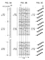
- Fig. 3A schematically illustrates a nozzle column of the recording head
- Fig. 3B schematically illustrates driving signals applied to the respective nozzles
- Fig. 3C schematically illustrates ink droplets ejected from the respective nozzles.
- a nozzle column 300 of the inkjet recording head is constituted by 128 nozzles, and these nozzles are divided in units of 16 nozzles into eight sections (groups) from a first section to an eighth section from the top of Fig. 3A .
- respective 16 nozzles in the respective sections belong to one of 16 driving blocks and are temporally divided in units of block and sequentially driven at the time of the recording.
- the nozzles in the same block are driven at the same time.
- 16 nozzles having nozzle numbers 1, 17, ⁇ , 113 in the nozzle column 300 belong to a first driving block (driving block No. 1)
- 16 nozzles having nozzle numbers 2, 18, ⁇ , 114 belong to a second driving block (driving block No. 2).
- 16 nozzles having nozzle numbers 16, 32, ⁇ , 128 belong to a sixteenth driving block (driving block No. 16), and the nozzles in the respective sections are periodically allocated to the respective driving blocks.
- the driving blocks Nos In the case of the time division driving where the driving blocks Nos.
- the respective heaters are sequentially driven by pulsed driving signals 301 illustrated in Fig. 3B .
- the recording data of the one column is data for turning the 128 nozzles ON
- ink droplets 302 are ejected from the respective nozzles in response to the driving signals as illustrated in Fig. 3C . Accordingly, the ink droplets based on the recording data of the same column are ejected in the time division manner. In the next cycle, the ink droplets based on the recording data of the next column can be similarly ejected in the time division manner.
- Fig. 4 is a flow chart for describing the processing of completing the same area by four scannings.
- step 401 an original image signal having respective 256 tones (0 to 255) for RGB obtained by an image input device such as a digital camera or a scanner or obtained computer processing or the like is input to a printer driver of the host PC E5000 at a resolution of 600 dpi.
- step 402 the RGB original image signal input in step 401 is converted into an R'G'B' signal.
- the R'G'B' signal is converted into signal values corresponding to the respective colors of ink.
- the recording apparatus according to the exemplary embodiment is constituted by three colors including C (cyan), M (magenta), and Y (yellow). Therefore, signals after the conversion are image signals C1, M1, and Y1 corresponding to the ink colors of cyan, magenta, and yellow.
- the numbers of tones of the respective image signals C1, M1, and Y1 are 256 (0 to 255), and the resolution is 600 dpi.
- step 404 tone of the image signal C1 is corrected through tone correction using a tone correction table, an image signal C2 after the tone correction is obtained.
- step 405 multi-value quantization processing based on an error diffusion method is performed to obtain an image signal C3 having a resolution of 600 dpi with three tones (0, 1, and 2) with regard to each pixel.
- the error diffusion method is used, but a dither method may also be used.
- the obtained image signal C3 is transmitted to the recording apparatus.
- the image signal C3 is subjected to a nozzle column development table illustrated in Fig. 5 to obtain an image signal C4 in each nozzle column.
- Fig. 5 a nozzle column development table
- step 407 multi-value mask processing is performed, and the image signal C4 is collated with a multi-value mask to obtain an image signal C5 that determines whether or not the ink droplet is arranged in the pixel area equivalent to the pixel on the sheet.
- a resolution of the multi-value mask is 600 dpi and has mask values corresponding to three values (0, 1, and 2). As illustrated in Fig.
- the ink droplets are not arranged in response to the signal value "0" of the image signal C4 in a case where the mask value is any of the value.
- the ink droplets are arranged in response to the signal value "1" of the image signal C3 only in a case where the mask value is 1.
- the ink droplets are arranged in response to the signal value "2" of the image signal C3 in a case where the mask value is "1" or "2".
- the mask value "1" permits maximum two ink ejections with respect to the pixel area
- the mask value "2" permits maximum one ink ejection with respect to the pixel area.
- the multi-value mask used in the present exemplary embodiment is constituted by four multi-value masks MP1, MP2, MP3, and MP4 having a width of 32 in the Y direction and a width of 32 in the X direction.
- Figs. 7A to 7F illustrate the multi-value mask patterns.
- Fig. 7A illustrates MP1
- Fig. 7B illustrates MP2
- Fig. 7C illustrates MP3
- Fig. 7D illustrates MP4, in which a white part represents the mask value "0”, a hatched part represents the mask value "1", and a black part represents the mask value "2".
- the ink droplet is to be arranged once in any of the four multi-value masks MP1 to MP4 with respect to the signal value "1" of the image signal C4, and the ink droplet is to be arranged twice in any of the four multi-value masks MP1 to MP4 with respect to the signal value "2" of the image signal C4.
- a vertically long houndstooth check in which the mask values "1" and "2" are mutually periodic is obtained ( Fig. 7E ).
- the multi-value mask used herein is a pattern in which houndstooth checks having lengths of 3 x 3 x 2 in the Y direction and a length of 1 in the X direction are repeated.
- a houndstooth check in which the mask values "1" and "2" are inverted with respect to the above-described arrangement is obtained ( Fig. 7F ).
- step 408 the image signal C5 is transmitted to the head.
- step 409 the ink is ejected to the pixel area equivalent to the pixels on the recording medium on the basis of the image signal C5.
- the heaters are driven on the basis of the time division driving to eject the ink to carry out the recording.
- Figs. 8A to 8C illustrate a relationship between the heater driving order and the arrangement of the ink droplets on the sheet based on the above-described driving order.
- Fig. 8A is a table indicating the heater driving order used in the present exemplary embodiment.
- the nozzles of the driving block No. 1 in the respective nozzle sections eject the ink (nozzle numbers 1, 17, ⁇ , 113).
- the nozzles of the driving block No. 9 in the respective nozzle sections eject the ink (nozzle numbers 9, 25, ⁇ , 118).
- the driving block No. 6 in the third place and the driving block No. 14 in the third place follow. Until the nozzles of the driving block No.
- the ink is ejected within a scanning width of 600 dpi.
- the arrangement of the ink droplets on the sheet corresponds to the arrangement illustrated in Fig. 8B .
- Fig. 9 is a schematic diagram illustrating a relationship between the recording medium conveyance and the nozzles to be used when the image is formed.
- the C column is used for the descriptions as the nozzle column, but the M column and the Y column also have the same relationship.
- the multi-value masks MP1 to MP4 are repeatedly used in the X direction.
- the nozzle numbers 1 to 32 are used, and the scanning is performed in the +X direction (forward direction) to carry out the recording.
- the recording data at this time is the image signal C5 obtained by collating the multi-value mask MP1 with the image signal C4 corresponding to a formed image area A (M1 in the drawing).
- the arrangement of the ink droplets on the sheet in accordance with the time division driving corresponds to the arrangement illustrated in Fig. 8B .
- the recording medium P is conveyed by 32 in units of 600 dpi in the +Y direction.
- Fig. 9 illustrates a relative positional relationship between the nozzles and the recording medium by moving the nozzles in the -Y direction.
- the nozzle numbers 1 to 64 are used, and the scanning is performed in the -X direction (backward direction) to carry out the recording.
- the recording data at this time is the image signal C5 obtained by collating the multi-value mask MP1 with the image signal C4 corresponding to a formed image area B with regard to the nozzle numbers 1 to 32.
- the recording data at this time is the image signal C5 obtained by collating the multi-value mask MP2 with the image signal C4 corresponding to the formed image area A with regard to the nozzle numbers 33 to 64 (M2 in the drawing).
- the arrangement of the ink droplets on the sheet in accordance with the time division driving corresponds to the arrangement illustrated in Fig. 8C .
- the recording medium P is conveyed by 32 in units of 600 dpi in the +Y direction.
- the nozzle numbers 1 to 96 are used, and the scanning is performed in the +X direction (forward direction) to carry out the recording.
- the recording data at this time is the image signal C5 obtained by collating the multi-value mask MP1 with the image signal C4 corresponding to a formed image area C with regard to the nozzle numbers 1 to 32.
- the recording data at this time is the image signal C5 obtained by collating the multi-value mask MP2 with the image signal C4 corresponding to the formed image area B with regard to the nozzle numbers 33 to 64.
- the recording data at this time is the image signal C5 obtained by collating the multi-value mask MP3 with the image signal C4 corresponding to the formed image area A with regard to the nozzle numbers 65 to 96 (M3 in the drawing).
- the arrangement of the ink droplets on the sheet in accordance with the time division driving corresponds to the arrangement illustrated in Fig. 8B .
- the recording medium P is conveyed by 32 in units of 600 dpi in the +Y direction.
- the nozzle numbers 33 to 128 are used, and the scanning is performed in the -X direction (backward direction) to carry out the recording.
- the recording data at this time is the image signal C5 obtained by collating the image signal C4 corresponding to the formed image area C with the multi-value mask MP2 with regard to the nozzle numbers 33 to 64.
- the recording data at this time is the image signal C5 obtained by collating the multi-value mask MP3 with the image signal C4 corresponding to the formed image area B with regard to the nozzle numbers 65 to 96.
- the recording data at this time is the image signal C5 obtained by collating the multi-value mask MP4 with the image signal C4 corresponding to the formed image area A with regard to the nozzle numbers 97 to 128 (M4 in the drawing).
- the arrangement of the ink droplets on the sheet in accordance with the time division driving corresponds to the arrangement illustrated in Fig. 8C .
- the recording of the formed image area A is completed by the four scannings in step 901 to 904. In this manner, the recording of the unit area (herein, the formed image area A) is performed by the plural scannings. After the scanning, the recording medium P is conveyed by 32 in units of 600 dpi in the +Y direction.
- step 905 the nozzle numbers 65 to 128 are used, and the scanning is performed in the +X direction (forward direction) to carry out the recording.
- the recording data at this time is the image signal C5 obtained by collating the multi-value mask MP3 with the image signal C4 corresponding to the formed image area C with regard to the nozzle numbers 65 to 96.
- the recording data at this time is the image signal C5 obtained by collating the multi-value mask MP4 with the image signal C4 corresponding to the formed image area B with regard to the nozzle numbers 96 to 128.
- the arrangement of the ink droplets on the sheet in accordance with the time division driving corresponds to the arrangement illustrated in Fig. 8B .
- the recording of the formed image area B is completed by the four scannings in steps 902 to 905.
- the recording medium P is conveyed by 32 in units of 600 dpi in the +Y direction.
- the nozzle numbers 97 to 128 are used, and the scanning is performed in the -X direction to carry out the recording.
- the recording data at this time is the image signal C5 obtained by collating the multi-value mask MP4 with the image signal C4 corresponding to the formed image area C.
- the arrangement of the ink droplets on the sheet in accordance with the time division driving corresponds to the arrangement illustrated in Fig. 8C .
- the recording of the formed image area C is completed by the four scannings in step 903 to 906. After the scanning, the recording medium P is discharged, and the recording operation is ended.
- the ink droplets are arranged at the locations having the mask values "1" and "2". That is, the ink droplets are arranged in the hatched parts and the black parts illustrated in Fig. 7A in the first scanning, Fig. 7B in the second scanning, Fig. 7C in the third scanning, and Fig. 7D in the fourth scanning.
- the recording is performed in the +X direction (forward direction) in the first scanning and the third scanning, and the recording is performed in the - X direction (backward direction) in the second scanning and the fourth scanning.
- the locations where the ink droplets are arranged in the +X direction (forward direction) are the hatched parts and the black parts illustrated in Fig. 7E
- the locations where the ink droplets are arranged in the -X direction (backward direction) are the hatched parts and the black parts illustrated in Fig. 7F . That is, the ink droplets are arranged once in the forward direction recording and once in the backward direction recording in all the pixels.
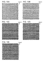
- FIG. 10A to 10E illustrate ink droplet arrangements (hereinafter, will be referred to as dot arrangements) at this time while the time division driving is also taken into account.
- Fig. 10A illustrates the dot arrangement in the +X direction (forward direction)
- Fig. 10B illustrates the dot arrangement in the -X direction (backward direction)
- Fig. 10C illustrates the final dot arrangement in which both the forward scanning and the backward scanning are overlapped with each other.
- Fig. 10A illustrates the dot arrangement in the +X direction (forward direction)
- Fig. 10B illustrates the dot arrangement in the -X direction (backward direction)
- Fig. 10C illustrates the final dot arrangement
- rows in which the dots based on the forward scanning and the dots based on the backward scanning are substantially overlapped with each other to be recorded, rows in which the dots are partially overlapped with each other, and rows in which the dots are hardly overlapped with each other to be displaced from each other and recorded exist in diverse ways.
- the dots in the row in which the dots are overlapped with each other newly appear but the dots in the row in which the dots are hardly overlapped with each other to be displaced from each other are newly overlapped with each other, so that the change in the density is cancelled out as a result.
- Fig. 10E the same arrangement as that of Fig.
- the ink droplets are arranged in the locations having the mask value "1". That is, the ink droplets are arranged in the gray parts illustrated in Fig. 7A in the first scanning, Fig. 7B in the second scanning, Fig. 7C in the third scanning, and Fig. 7D in the fourth scanning.
- the recording is performed in the +X direction (forward direction) in the first scanning and the third scanning, and the recording is performed in the -X direction (backward direction) in the second scanning and the fourth scanning.
- the locations where the ink droplets are arranged in the +X direction (forward direction) are the gray parts illustrated in Fig. 7E
- the locations where the ink droplets are arranged in the -X direction (backward direction) are the gray parts illustrated in Fig. 7F . That is, the ink droplets are arranged with respect to a staggered arrangement of one pixel x one pixel in the forward direction recording and in an inversely staggered arrangement that complements the above-described staggered arrangement in the backward direction recording.
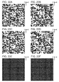
- Figs. 11A to 11E illustrate dot arrangements at this time in which the time division driving is also taken into account.
- Fig. 11A illustrates the dot arrangement in the +X direction (forward direction)
- FIG. 11B illustrates the dot arrangement in the -X direction (backward direction), and Fig. 11C illustrates the final dot arrangement in which both the forward scanning and the backward scanning are overlapped with each other.
- the tone in which one dot is arranged per pixel to the tone in which two dots are arranged per pixel, it is possible to suppress the decrease in the image uniformity and the change in the density which appear when the landing displacement between the scannings occurs.
- the advantage is attained in the two aspects in which the ink landing positions based on the time division driving are varied in the scannings and the recording is performed in the adjacent pixels in different scanning directions.
- Figs. 12A to 12D illustrate the heater driving order and the arrangement of the ink droplets on the sheet based on the above-described driving order
- Figs. 13A to 13F illustrate the multivalue mask pattern.
- the other recording operations are the same as those according to the above-described exemplary embodiment.
- Fig. 12A is a table indicating the heater driving order at the time of the scanning in the +X direction (forward direction).
- Fig. 12B is a table indicating the heater driving order at the time of the scanning in the -X direction (backward direction).
- Fig. 12D illustrates the arrangement illustrated in Fig. 12D .
- Fig. 13A illustrates the multi-value mask used in the first scanning
- Fig. 13B illustrates the multi-value mask used in the second scanning
- Fig. 13C illustrates the multi-value mask used in the third scanning
- Fig. 13D illustrates the multi-value mask used in the fourth scanning.
- Fig. 13E illustrates the arrangement recorded by the forward scanning in the first scanning + the third scanning
- Fig. 13F illustrates the arrangement recorded by the backward scanning in the second scanning + the fourth scanning.
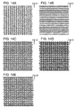
- FIG. 14A to 14E illustrate a dot arrangement in a case where the value of the image signal C4 becomes "2" in all the pixels
- Figs. 15A to 15E illustrate a dot arrangement in a case where the value of the image signal C4 becomes "1" in all the pixels
- Fig. 14A and Fig. 15A illustrate the dot arrangement in the +X direction (forward direction)
- Fig. 14B and Fig. 15B illustrate the dot arrangement in the -X direction (backward direction)
- Fig. 14C and Fig. 15C illustrate the final dot arrangement in which both the forward scanning and the backward scanning are overlapped with each other.
- the image uniformity hardly changes, but with regard to the density, it may be understood that the density is increased when the situation is changed from no displacement to the occurrence of the displacement at 21.2 um, and the density is decreased when the displacement is increased from 21.2 um to 42.3 um.
- Fig. 15D it may be understood that parts where the mutual dots are partially overlapped with each other which do not appear at all in Fig. 15C .
- Fig. 15E the mutual dots are further overlapped with each other.
- the gaps between the dots are uniform in Fig. 15C , but the gaps between the dots are partially expanded in Fig. 15D , and the gaps are further expanded in Fig.
- the arrangement of the ink droplets based on the time division driving order are varied in the forward scanning and the backward scanning, so that the decrease in the image uniformity and the change in the density are suppressed which appear when the landing displacement between the scannings occurs.
- a method for varying the arrangements of the ink droplets based on the time division driving order in the scannings a large effect is attained when the correspondence relationship based on the mirror inversion which is also illustrated in the exemplary embodiment is established.
- the time division driving order is set in a manner that the ink is ejected from the nozzles of the driving block No. 1 in the respective nozzle sections in the first place, the ink is ejected from the nozzles of the driving block No. 2 in the respective nozzle sections in the second place, the ink is ejected from the nozzles of the driving block No. 3 in the third place, ⁇ , and the ink is ejected from the driving block No. 16 in the sixteenth place as the driving order.
- the dots are sequentially arranged from the block No. 1 to the block No.
- the dots are sequentially arranged from the block No. 1 to the block No. 16 in the -X direction in the case of the backward direction recording.
- the pattern in which the backward direction recording ⁇ the forward direction recording ⁇ the backward direction recording- the forward direction recording are arranged alternately for every column is adopted.
- the mask size of the present exemplary embodiment is 32 in both the vertical direction and the horizontal direction, but as seen in the repetition cycle of the mask pattern, the Y direction is 8, and the X direction is 2.
- Figs. 16A to 16C illustrate dot coordinates in a case where the signal value in all the pixels for the image signal C4 having the size of 16 in the vertical direction x 4 in the horizontal direction on the basis of the above-described driving order and the mask pattern is "1".
- Fig. 16A illustrates the dot coordinates in a case where the displacement between the forward and backward scannings does not occur, Fig.
- a cell filled with the vertical lines indicates a location where the dot is arranged by the forward direction recording
- a cell filled with the horizontal lines indicates a location where the dot is arranged by the backward direction recording.
- the vertical size of the cell is 600 dpi
- the dot in the backward direction is arranged in the X direction at T4 in C2
- the dot in the forward direction is arranged at the adjacent T5 in C2. From that point, a blank space continues for 30 cells.
- the dot in the backward direction is arranged at T4 in C4, and the dot in the forward direction is arranged at the adjacent T5 in C4.
- the relationship between the forward direction and the backward direction with respect to this dot coordinate is the same as that in the first row (R1) in Fig. 16A .
- the relationship between the forward direction and the backward direction with respect to the dot coordinate in the sixth row (R6) in Fig. 16B is the same as that in the second row (R2) in Fig. 16A .
- a pair having the same relationship between the forward direction and the backward direction with respect to the dot coordinate is to exist in Fig. 16B and Fig. 16A .
- the ninth row (R9) in Fig. 16C it may be understood that the situation is the same as the first row (R1) in Fig. 16A .
- the tenth row (R10) in Fig. 16C the situation is the same as the second row (R2) in Fig. 16A , for example.
- a pair having the same relationship between the forward direction and the backward direction with respect to the dot coordinate is to exist in Fig. 16C and Fig. 16A too. This is because the dot arrangement based on the time division driving has the mirror inversion in the forward direction and the backward direction, and the relationship between the forward direction and the backward direction with respect to the dot coordinate is varied in all the rows.
- the pair having the same relationship between the forward direction and the backward direction as that in a case where no displacement occurs is to exist, and it is possible to suppress the change in the density in a case where the displacement between the forward and backward scannings occurs.
- Figs. 17A to 17C correspond to the change to the time division driving order ( Figs. 8A to 8C ) with respect to Figs.
- FIG. 16A to 16C A cell filled with the vertical lines indicates a location where the dot is arranged in the forward direction recording, and a cell filled with the horizontal lines indicates a location where the dot is arranged in the backward direction recording.
- Fig. 17A corresponds to a case where the displacement between the forward and backward scannings does not occur
- a cell further displaced to the right side with respect to the column C4 is regarded as going around and added to the column C1.
- the rows in which the coordinate relationship between the forward direction and the backward direction are matched with each other are to exist as in R5 in Fig. 17C and R1 in Fig. 17A , R6 in Fig. 17C and R2 in Fig. 17A , R7 in Fig. 17C and R3 in Fig. 17A , ⁇ .
- the dots are concentrated in the column C2 and the column C4, and the image uniformity is degraded.
- the feature of the mask pattern in the same scanning direction is changed to a pattern in which a particular row is shifted in the X direction instead of the pattern in which the backward direction recording ⁇ the forward direction recording ⁇ the backward direction recording- the forward direction recording are alternately arranged. Even when the particular row is shifted in the X direction, the relationship between the forward direction and the backward direction with respect to the dot coordinate in the row is not changed, and the rows in which the coordinate relationship between the forward direction and the backward direction are matched with each other continue to exist.
- a pattern in which the rows 1, 2, 3, 7, 8, 9, 10, 11, 15, and 16 are shifted in the X direction by +1 column is equivalent to the houndstooth check pattern of the exemplary embodiment, which will be described as an example.
- Figs. 18A to 18C illustrate a configuration in which changes are made to the time division driving order ( Figs. 8A to 8C ) and the multi-value mask pattern ( Fig. 7E and Fig. 7F ) with respect to the configuration of Figs. 16A to 16C .
- FIG. 18A corresponds to a case where the displacement between the forward and backward scannings does not occur
- a cell filled with the vertical lines indicates a location where the dot is arranged in the forward direction recording
- a cell filled with the horizontal lines indicates a location where the dot is arranged in the backward direction recording.
- Figs. 19A to 19C illustrate an example in which the dot arrangement based on the time division driving in the forward direction and the dot arrangement based on the time division driving in the backward direction are the same in all the rows. Similarly as in Figs.
- a cell filled with the vertical lines indicates a location where the dot is arranged in the forward direction recording
- a cell filled with the horizontal lines indicates a location where the dot is arranged in the backward direction recording.
- a driving order is set such that, with regard to the forward direction, the ink is ejected from the nozzles of the driving block No. 1 in the respective nozzle sections in the first place, the ink is ejected from the nozzles of the driving block No. 2 in the respective nozzle sections in the second place, the ink is ejected from the nozzles of the driving block No.
- a driving order is set such that, with regard to the backward direction, the ink is ejected from the nozzles of the driving block No. 16 in the respective nozzle sections in the first place, the ink is ejected from the nozzles of the driving block No. 15 in the respective nozzle sections in the second place, the ink is ejected from the nozzles of the driving block No. 14 in the third place, ⁇ , and the ink is ejected from the nozzles of the driving block No. 1 in the sixteenth place.
- the dots are sequentially arranged in the +X direction from the block No.
- Fig. 19A corresponds to a case where the displacement between the forward and backward scannings does not occur
- Fig. 19A corresponds to a case where the displacement between the forward and backward scannings does not occur
- Fig. 19A corresponds to a case where the displacement between the forward and backward scannings does not occur
- Fig. 19B corresponds to a case where the displacement amount between the forward and
- the dots in the forward direction and the dots in the backward direction are arranged while blank space for 15 cells are arranged in all the rows.
- the blank space is changed from 15 cells to eight cells.
- Fig. 19C no blank space appears, and the dots in the forward direction and the dots in the backward direction are overlapped with each other in all the rows. That is, in a case where the displacement between the forward and backward scannings occurs, the distance at which the dots are arranged in the forward and backward directions is changed in all the rows.
- a configuration is preferably adopted in which the relationship between the forward scanning and the backward scanning with regard to the dot coordinates is not the same, and furthermore, the dot arrangement in the backward scanning is not an dot arrangement obtained through offset of the dot arrangement in the forward scanning.
- the patterns of the dot arrangements in the respective forward and backward scannings are not similar to each other, and the above-described cancelling effect of the change in the density is increased.
- an offset relationship in which the driving order with respect to the array of the nozzle is an inverse order is not established in the forward scannings and the backward scanning.
- the heater driving order and the arrangement of the ink droplets on the sheet based on the above-described driving order use the configuration illustrated in Figs. 8A to 8C in which the mirror arrangement is established in the forward and backward scanning directions, and the multi-value mask pattern uses the configuration illustrated in Figs. 13A to 13F in which in which scanning direction is randomly determined to record the adjacent pixels in response to the mask value "1".
- the other recording operations are the same as those according to the above-described exemplary embodiment.
- Figs. 20A to 20E illustrate the dot arrangement in a case where the value of the image signal C4 becomes "1" in all the pixels by adopting the time division driving order of Figs. 8A to 8C and the multi-value mask pattern of Figs. 13A to 13F .
- Fig. 20A illustrates the dot arrangement in the +X direction (forward direction)
- Fig. 20B illustrates the dot arrangement in the -X direction (backward direction)
- Fig. 20C illustrates the final dot arrangement in which both the forward scanning and the backward scanning are overlapped with each other.
- Fig. 20A illustrates the dot arrangement in the +X direction (forward direction)
- Fig. 20B illustrates the dot arrangement in the -X direction (backward direction)
- Fig. 20C illustrates the final dot arrangement in which both the forward scanning and the backward scanning are overlapped with each other.
- Fig. 20D illustrates the dot arrangement in a case where the backward scanning recording is displaced in
- Descriptions of the distance in the X direction between the dots arranged in the same nozzle, the distance in the X direction between the first block and the second block, the part filled with the vertical lines, the part filled with the horizontal lines, and the part filled with the grid lines are the same as the above.
- Fig. 20D it looks like that the blank area is slightly increased as compared with Fig. 20C .
- Fig. 20E the increase in the blank area becomes conspicuous.
- the number of the gaps between the dots is low, but the gaps exist in a non-uniform manner with reference to Fig. 20C .
- the above-described gaps between the dots are partially expanded.
- the gaps are further expanded, and the non-uniformity of the gaps becomes conspicuous.
- the ink droplet arrangement based on the time division driving is varied in the forward direction and the backward direction to generate a location where the dots are overlapped with each other (that is, the ink landing positions in the forward direction recording and the backward direction recording are close to each other) and a location where the dots are not overlapped with each other (that is, the ink landing positions in the forward direction recording and the backward direction recording are far from each other).
- an image robustness with respect to the displacement between the scannings can be improved.
- the adjacent dots when the adjacent dots are arranged in the same scanning direction, the adjacent dots have the arrangement based on the same time division driving order. Therefore, the landing positions between the dots are at a distance that is neither close nor far.
- the scanning directions for the adjacent dots are preferably varied.
- the adjacent pixels are partially arranged in the same scanning direction.
- the above-described arrangement of the pixels in the forward direction recording and the backward direction recording has the relationship of the houndstooth check or the inverted houndstooth check, all the adjacent pixels are arranged in the different scanning directions, and the effect is conspicuous.
- all the adjacent pixels do not necessarily need to be arranged in different scanning directions, and when the number of the adjacent pixels is higher than the pixel that are not adjacent to each other in all the rows, it is possible to attain the sufficient effect of suppressing the density fluctuation based on the above-described driving order.
- the houndstooth check pattern of the houndstooth checks having the lengths of 3 x 3 x 2 in the Y direction and the length of 1 in the X direction ( Fig. 7E and Fig. 7F ) is used according to the exemplary embodiment, but the present invention is not limited to this.
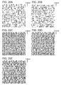
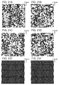
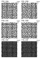
- Figs. 21A to 21F and Figs. 22A to 22F illustrate the multi-value mask pattern arranged in the forward scanning direction.
- Fig. 21A and Fig. 22A illustrate the multi-value mask used in the first scanning
- Fig. 21B and Fig. 22B illustrate the multi-value mask used in the second scanning
- FIG. 21C and Fig. 22C illustrate the multi-value mask used in the third scanning
- Fig. 21D and Fig. 22D illustrate the multi-value mask used in the fourth scanning.
- the white part indicates the mask value "0”
- the hatched part indicates the mask value "1”
- the black part indicates the mask value "2”.
- Fig. 21E and Fig. 22E illustrate the arrangement where the recording is performed by the forward scanning based on the first scanning + the third scanning
- Fig. 21F and Fig. 22F illustrate the arrangement where the recording is performed by the backward scanning based on the second scanning + the fourth scanning.
- a houndstooth check pattern having a size of a length of 4 in the Y direction ⁇ a length of 1 in the X direction as illustrated in Fig. 21E and Fig. 21F may be used.
- a houndstooth check pattern having a size of a length of 1 in the Y direction x a length of 1 in the X direction as illustrated in Fig. 22E and Fig. 22F may be used. That is, any pattern in which the dots are dispersed to be arranged when the pattern is combined with the time division driving order may be used. A repetition pattern size smaller than the number of blocks in the time division driving is preferably used.
- the dot arrangement is not changed for each section, and there is little fear that the dot arrangement is visually recognized as a texture.
- the houndstooth check pattern as described above is the dot arrangement having a relatively satisfactory dispersibility even in a state in which the displacement between the forward and backward scannings does not occur, a pattern having a large number of high-frequency components and a high intensity in a case where the pattern is subjected to a frequency analysis is preferably used as the multi-value mask pattern arranged in the forward scanning direction.
- the multi-value mask pattern used in the first exemplary embodiment (MP1 to MP4), the pattern arranged in the forward scanning (MP1 + MP3), and the pattern arranged in the backward scanning (MP2 + MP4) are the vertically long houndstooth check pattern, and the high-frequency components are dominant.
- the pattern itself for each scanning (MP1, MP2, MP3, MP4) has a white noise characteristic in which a spatial frequency is not particularly high.
- an irregular displacement for example, a conveyance displacement
- the pattern for each scanning also preferably has the characteristic of the high spatial frequency.
- Figs. 23A to 23F illustrate examples thereof.
- Fig. 23A illustrates the multi-value mask used in the first scanning
- Fig. 23B illustrates the multi-value mask used in the second scanning
- Fig. 23C illustrates the multi-value mask used in the third scanning
- Fig. 23D illustrates the multi-value mask used in the fourth scanning.
- the white part indicates the mask value "0”
- the hatched part indicates the mask value "1”
- the black part indicates the mask value "2”.
- Fig. 23E illustrates an arrangement in which the recording is performed by the forward scanning based on the first scanning + the third scanning
- Fig. 23E illustrates an arrangement in which the recording is performed by the forward scanning based on the first scanning + the third scanning
- Fig. 23E illustrates an arrangement in which the recording is performed by the forward scanning based on the first scanning + the third scanning
- FIG. 23F illustrates an arrangement in which the recording is performed by the backward scanning based on the second scanning + the fourth scanning.
- the pattern arranged in the forward scanning ( Fig. 23E ) and the pattern arranged in the backward scanning ( Fig. 23F ) are the same as Fig. 7E and Fig. 7F .
- the pattern for each scanning ( Fig. 23A, Fig. 23B, Fig. 23C, and Fig. 23D ) has suppressed low-frequency components and more high-frequency components as compared with the pattern of Figs. 13A to 13F .
- These four patterns are a pattern in which an intermediate image based on the dots formed by the respective scannings have a blue noise characteristic.
- These patterns can be obtained in a manner that recording permit pixels of the mask patterns are determined while paying attention to indices related to the dispersity of the dots in a designing stage of the mask patterns, and the level of the characteristic related to the spatial frequency is set to be close to a desired level.
- the case has been described where the recording of the predetermined image formation area is completed by the four scannings.
- the multi-value mask pattern (MP1 + MP3) of Fig. 7E is used in the first scanning
- the multi-value mask pattern (MP2 + MP4) of Fig. 7F is used in the second scanning.
- the multi-value mask pattern (MP1 + MP3) of Fig. 7E is decomposed into four multi-value mask patterns (MP1 + MP3_1, MP1 + MP3_2, MP1 + MP3_3, and MP1 + MP3_1_4).
- the multi-value mask pattern (MP2 + MP4) of Fig. 7F is also decomposed into four multi-value mask patterns (MP2 + MP4_1, MP2 + MP4_2, MP2 + MP4_3, and MP2 + MP4_4).
- the recording apparatus executes a second mode for adjusting the recording position (registration adjustment) to the recording medium by the recording head.
- This mode is separately prepared in addition to a first mode for recording an actual image in which the recording of the image specified by the user is performed.
- This mode is a mode of recording a test pattern (registration adjustment pattern) for the registration adjustment, and the recording of the actual image can be performed after the user performs the registration adjustment.
- Fig. 27B is a flow chart of the registration adjustment executed by the recording apparatus.
- the ASIC E1102 causes the recording head 102 to record the registration adjustment pattern ( Fig. 27B : 2701).
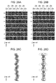
- Figs. 25A and 25B illustrate examples of the registration adjustment pattern.
- Fig. 25A illustrates a reference pattern 25a for a registration adjustment pattern.
- rectangular patterns having 16 dots in the X direction at 1200 dpi and 96 dots in the Y direction at 600 dpi are arranged in the X direction at a predetermined interval. The interval between the mutual rectangular patterns is equivalent to 16 dots at 2400 dpi.
- Fig. 25B illustrates an adjustment pattern 25b recorded while reflecting the registration adjustment value.
- the one reference pattern is recorded by the same nozzle column.
- the one adjustment pattern is recorded by the same nozzle column. Descriptions related to these configurations will be given below. Data of the patterns stored in the ROM E1004 is used.
- the recording positions of the reference pattern and the adjustment pattern are displaced by a predetermined amount, and the registration adjustment patterns are printed on the recording medium as illustrated in Fig. 26A .
- the plurality of registration adjustment patterns are formed by shifting the registration adjustment values in units of 1200 dpi (approximately 21.2 ⁇ m) from +3 to -3 by the decrement of 1, and numbers on the left side of the registration adjustment patterns are the registration adjustment values.
- the formation is made by controlling the ink ejection timings on the basis of the registration adjustment values.
- the control on the shifting amount is performed by controlling the driving timing of the recording element for ejecting the ink in accordance with the movement based on the scanning of the carriage by the head control signal E1021 while the ASIC E1102 detects the signal from the encoder sensor E0004.
- This registration adjustment pattern is formed by shifting the ink landing position for recording the adjustment pattern while the ejection timing is advanced or delayed with respect to the reference pattern.
- the shifting amount of this driving timing corresponds to the registration adjustment value.
- Numbers -3 to +3 indicated on the side of the registration adjustment patterns of Fig. 26A are the registration adjustment values.
- a side on which the driving timing of the adjustment pattern is advanced with respect to the reference pattern is set as "+”, and the driving timing of the adjustment pattern is delayed with respect to the reference pattern is set as "-”.
- the registration adjustment value is input from a screen or the like of a driver (not illustrated) through the host PC E5000 or the front panel E0106 from the user.
- the ASIC E1102 determines that the accepted input registration adjustment value is used in the actual image recording mode (2703) and stores this value in the EEPROM E1005 ( Fig. 27B : 2704).
- the driving timing of the recording element for the ink ejection in accordance with the movement based on the carriage scanning is controlled by the head control signal E1021 on the basis of this registration adjustment value.
- the registration adjustment patterns corresponding to the respective registration adjustment values the distance in the X direction between the reference pattern 25a and the adjustment pattern 25b is not changed in accordance with the position in the Y direction.
- a relationship between the array of the dots in the Y direction forming the same column and the relative position in the X direction between the dots is the same in the reference pattern 25a and the adjustment pattern 25b.
- the relationship with regard to the dot arrangements between the reference pattern 25a and the adjustment pattern 25b herein is the same as the relationship between the dot arrangement in the forward direction recording and the dot arrangement in the backward direction recording described with reference to Figs. 19A to 19C .
- the recording apparatus performs the control on the recording similarly as in the control on the time division driving at the time of the above-described image recording.
- Fig. 25C illustrates a type and a reference of a registration adjustment item, adjustment, and allocation of the nozzles for recording the respective patterns.
- the plurality of reference patterns 25a are recoded in the forward direction by the column of the nozzles 202 for ejecting the ink amount of 5 pl in the C column in Fig. 2C .
- the plurality of adjustment pattern 25b having different shifting amounts with respect to the reference in the backward direction by the same nozzle column, it is possible to form the registration adjustment pattern between the forward scanning and the backward scanning with regard to the nozzle column for 5 pl in the C column.
- the registration adjustment between the forward scanning and the backward scanning can be performed on the basis of this pattern. The same may also apply to the nozzle column for 2 pl of Fig. 2C .
- the registration adjustment between the nozzles for 5 pl and 2 pl in the C column can be performed.
- the reference pattern 25a is recorded by the scanning in the even column of the K column described with reference to Fig. 2B and the adjustment pattern 25b is recorded by the scanning in the odd column of the K column in the same direction, the registration adjustment between the even column and the odd column of the K column can be performed.
- the reference pattern 25a is recorded by several nozzles at the end on the sheet supply side in the odd column of the K column in Fig. 2B (upstream side in the Y direction), and after a predetermined conveyance is performed, the adjustment pattern 25b is recorded by several nozzles at the end on the sheet discharging side in the odd column of the K column (downstream side in Y direction).
- the registration adjustment pattern for the ⁇ registration adjustment.
- the registration adjustment value is determined by using this registration adjustment pattern, it is possible to adjust the recording position displacement caused by an inclination of the nozzle column.
- Fig. 26B illustrates the registration adjustment patterns corresponding to the respective registration adjustment values in a case where the respective registration adjustment patterns are recorded without changing the driving orders of the respective nozzles in the forward scanning and the backward scanning with regard to the registration adjustment between the forward scanning and the backward scanning.
- this registration adjustment pattern the relative relationship of the ink landing position in the X direction with respect to the array of the nozzle columns is inverted in the reference pattern and the adjustment pattern. Accordingly, the change in the density of the recorded pattern with respect to the slight recording position displacement between the forward scanning and the backward scanning is suppressed because of the above-described effect, as may be understood from the drawing, it is difficult to discriminate the registration adjustment patterns having different adjustment values.
- Fig. 26C schematically illustrates an adjoining border between the reference pattern 25a (horizontal line) and the adjustment pattern 25b (vertical line) of the registration adjustment pattern having the adjustment value of 0 in Fig. 26A .
- the dot arrangement in the X direction in accordance with the position in the Y direction is completely the same in the reference pattern 25a and the adjustment pattern 25b.
- Fig. 26D schematically illustrates an adjoining border between the reference pattern 25a (horizontal line) and the adjustment pattern 25b (vertical line) of the registration adjustment pattern having the adjustment value of 0.
- the registration adjustment pattern described in Fig. 26A is adopted according to the present exemplary embodiment.
- the driving of the recording element is performed such that, with regard to the same nozzle column, the driving order with respect to the array of the nozzles in the group is inverted in the forward scanning and the backward scanning.
- the driving of the recording element is performed such that, with regard to the same nozzle column, the driving order with respect to the array of the nozzles in the group in the backward direction scanning is not inverted to the driving order with respect to the array of the nozzles in the group in the forward direction scanning.
- the method for the user to visually check the pattern to select the adjustment value and input the adjustment value to the recording apparatus has been described as an example, but a mode in which the recording apparatus includes an optical sensor 2700 illustrated in Fig. 27A may be adopted such that the recording position adjustment processing can be automatically performed.
- the optical sensor 2700 can use the color development appropriately selected in accordance with an ink color tone used in the recording apparatus, the head configuration, or the like.
- a registration adjustment pattern may be created by using ink of a color having an excellent light absorption characteristic with respect to color development of a red LED or an infrared LED, and the red LED mounted to the optical sensor 2700 may read this the optical sensor 2700.
- black (Bk) or cyan (C) is preferably used, and magenta (M) or yellow (Y) does not obtain a sufficient density characteristic or signal to noise (S/N) ratio.
- M magenta
- S/N signal to noise
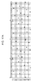
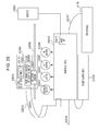
- Fig. 27A is a schematic diagram for describing the optical sensor 2700 used in the apparatus of Figs. 1Aand 1B .
- Fig. 27B illustrates a flow for the recording apparatus to perform the registration adjustment using the optical sensor 2700.
- the optical sensor 2700 is attached to the carriage 106 described above which is not illustrated in Fig. 27A and includes a light emitting unit 2701 and a light receiving unit 2702 as illustrated in Figs. 25A to 25C .
- the recording of the registration adjustment pattern in 2701 has been described above, and the descriptions thereof will be omitted.
- Light I in 2703 emitted from the light emitting unit 2701 is reflected by the recording medium P, and reflected light I REF 2704 can be detected by the light receiving unit 2702.
- the optical sensor 2700 reads a plurality of formed registration adjustment patterns ( Fig. 27B : 2702).
- the detection signal is transmitted to the main substrate side of the recording apparatus via the CRFFC E0012 and converted into a digital signal by an analog-to-digital (A/D) converter (not illustrated).
- A/D analog-to-digital
- the ASIC that has received the converted signal determines an appropriate registration adjustment value on the basis of the signal of each of the registration adjustment patterns corresponding to different registration adjustment values ( Fig. 27B : 2703) and stores the registration adjustment value in the EEPROM E1005 ( Fig. 27B : 2704).
- the recording apparatus may be an inkjet recording apparatus including a scanner such as a multi-function printer (MFP).
- MFP multi-function printer
- the user may set the printed registration adjustment pattern in a scanner. Then, the scanner may read the registration adjustment pattern to perform the above-described steps 2702 and 2703 in Fig. 27B and determine the adjustment value.
- the heaters that generate thermal energy for ejecting the ink are used as the recording elements as an example, but piezoelectric elements that perform mechanical displacement on the basis of driving signals may be used as the recording elements.
- transparent clear ink that overcoats the colored ink on the recording medium or reactive ink that reacts with the colored ink and increases a fixing property of the colored ink onto the recording medium can be also used as the "ink”.
- the exemplary embodiment of the present invention while the fluctuation in the density of the image which is caused by the displacement of the recording positions between the forward and backward scannings is suppressed in the image recording, it is possible to perform the more accurate adjustment in the adjustment processing of the recording positions between the forward and backward scannings.
Landscapes
- Engineering & Computer Science (AREA)
- Quality & Reliability (AREA)
- Ink Jet (AREA)
- Dot-Matrix Printers And Others (AREA)
Applications Claiming Priority (1)
| Application Number | Priority Date | Filing Date | Title |
|---|---|---|---|
| JP2015157714A JP6562761B2 (ja) | 2015-08-07 | 2015-08-07 | 記録装置および記録方法 |
Publications (3)
| Publication Number | Publication Date |
|---|---|
| EP3144150A2 true EP3144150A2 (fr) | 2017-03-22 |
| EP3144150A3 EP3144150A3 (fr) | 2017-10-18 |
| EP3144150B1 EP3144150B1 (fr) | 2021-03-31 |
Family
ID=56686640
Family Applications (1)
| Application Number | Title | Priority Date | Filing Date |
|---|---|---|---|
| EP16182322.4A Active EP3144150B1 (fr) | 2015-08-07 | 2016-08-02 | Appareil et procédé d'enregistrement |
Country Status (4)
| Country | Link |
|---|---|
| US (1) | US9855774B2 (fr) |
| EP (1) | EP3144150B1 (fr) |
| JP (1) | JP6562761B2 (fr) |
| CN (1) | CN106427211B (fr) |
Families Citing this family (9)
| Publication number | Priority date | Publication date | Assignee | Title |
|---|---|---|---|---|
| US10574662B2 (en) * | 2017-06-20 | 2020-02-25 | Bank Of America Corporation | System for authentication of a user based on multi-factor passively acquired data |
| JP6914779B2 (ja) * | 2017-08-10 | 2021-08-04 | キヤノン株式会社 | 記録装置、記録方法、およびプログラム |
| US11135834B1 (en) | 2017-11-13 | 2021-10-05 | Hewlett-Packard Development Company, L.P. | Interferential patterns for printer calibration |
| CN112020435B (zh) * | 2018-05-16 | 2022-07-08 | 惠普发展公司,有限责任合伙企业 | 确定光源的反射光强度的方法、打印设备和计算机可读介质 |
| JP7313943B2 (ja) * | 2019-07-17 | 2023-07-25 | キヤノン株式会社 | ディザパターンの作成方法、プログラムおよびディザパターンを作成する装置 |
| JP7419786B2 (ja) | 2019-12-13 | 2024-01-23 | 株式会社リコー | 液体吐出装置および方法、プログラム |
| JP7500321B2 (ja) * | 2020-07-29 | 2024-06-17 | キヤノン株式会社 | インクジェット記録方法及びインクジェット記録装置 |
| JP7551380B2 (ja) * | 2020-07-29 | 2024-09-17 | キヤノン株式会社 | 画像処理方法及び画像処理装置 |
| JP7483539B2 (ja) * | 2020-07-29 | 2024-05-15 | キヤノン株式会社 | 画像記録装置及び画像記録方法 |
Citations (2)
| Publication number | Priority date | Publication date | Assignee | Title |
|---|---|---|---|---|
| JPH0781190A (ja) | 1993-09-20 | 1995-03-28 | Canon Inc | インクテストプリント方法及びインクジェット記録装置 |
| JP2013159017A (ja) | 2012-02-03 | 2013-08-19 | Canon Inc | 記録装置及びその記録制御方法 |
Family Cites Families (17)
| Publication number | Priority date | Publication date | Assignee | Title |
|---|---|---|---|---|
| JP3332478B2 (ja) * | 1993-06-22 | 2002-10-07 | キヤノン株式会社 | 記録装置及び記録方法 |
| JP4323580B2 (ja) * | 1998-04-03 | 2009-09-02 | キヤノン株式会社 | プリント装置およびそのヘッド駆動方法 |
| US6315388B1 (en) * | 1998-10-30 | 2001-11-13 | Hewlett-Packard Company | Draft printing |
| EP1029673B1 (fr) | 1999-02-18 | 2006-06-28 | Hewlett-Packard Company, A Delaware Corporation | Système de correction d'erreurs de placement de gouttelettes dans l'axe de balayage pour imprimantes à jet d'encre |
| JP2001063016A (ja) | 1999-08-24 | 2001-03-13 | Canon Inc | プリント方法およびプリント装置 |
| US6997533B2 (en) | 2001-04-02 | 2006-02-14 | Canon Kabushiki Kaisha | Printing head, image printing apparatus, and control method employing block driving of printing elements |
| JP5065460B2 (ja) * | 2002-08-30 | 2012-10-31 | キヤノン株式会社 | 記録位置調整方法およびインクジェット記録装置 |
| JP4306214B2 (ja) * | 2002-10-03 | 2009-07-29 | セイコーエプソン株式会社 | プラテンギャップに応じた双方向印刷時の位置ズレ補正 |
| JP4193458B2 (ja) | 2002-10-03 | 2008-12-10 | セイコーエプソン株式会社 | 双方向印刷時の記録位置ずれの調整 |
| JP4401714B2 (ja) | 2003-09-04 | 2010-01-20 | キヤノン株式会社 | 記録装置 |
| US7549720B2 (en) | 2005-07-08 | 2009-06-23 | Canon Kabushiki Kaisha | Ink-jet recording device and ink-jet recording control method |
| JP2008307722A (ja) * | 2007-06-12 | 2008-12-25 | Canon Inc | 記録装置及びその記録方法 |
| US8608271B2 (en) | 2009-03-31 | 2013-12-17 | Canon Kabushiki Kaisha | Printing apparatus and printing method |
| JP2011037037A (ja) * | 2009-08-06 | 2011-02-24 | Canon Inc | 画像記録装置およびその制御方法 |
| JP5882567B2 (ja) * | 2010-08-19 | 2016-03-09 | キヤノン株式会社 | インクジェット記録装置、インクジェット記録装置におけるノズル駆動制御方法 |
| JP2013142809A (ja) | 2012-01-11 | 2013-07-22 | Konica Minolta Inc | 画像形成装置制御方法および画像形成装置 |
| JP6326793B2 (ja) | 2012-12-05 | 2018-05-23 | 株式会社リコー | 画像形成装置、画像位置ずれ調整方法及び画像位置ずれ調整プログラム |
-
2015
- 2015-08-07 JP JP2015157714A patent/JP6562761B2/ja active Active
-
2016
- 2016-08-02 US US15/226,797 patent/US9855774B2/en active Active
- 2016-08-02 EP EP16182322.4A patent/EP3144150B1/fr active Active
- 2016-08-05 CN CN201610639338.0A patent/CN106427211B/zh active Active
Patent Citations (2)
| Publication number | Priority date | Publication date | Assignee | Title |
|---|---|---|---|---|
| JPH0781190A (ja) | 1993-09-20 | 1995-03-28 | Canon Inc | インクテストプリント方法及びインクジェット記録装置 |
| JP2013159017A (ja) | 2012-02-03 | 2013-08-19 | Canon Inc | 記録装置及びその記録制御方法 |
Also Published As
| Publication number | Publication date |
|---|---|
| US9855774B2 (en) | 2018-01-02 |
| CN106427211A (zh) | 2017-02-22 |
| US20170036467A1 (en) | 2017-02-09 |
| JP2017035814A (ja) | 2017-02-16 |
| EP3144150A3 (fr) | 2017-10-18 |
| JP6562761B2 (ja) | 2019-08-21 |
| CN106427211B (zh) | 2018-08-31 |
| EP3144150B1 (fr) | 2021-03-31 |
Similar Documents
| Publication | Publication Date | Title |
|---|---|---|
| EP3144150B1 (fr) | Appareil et procédé d'enregistrement | |
| US9227398B2 (en) | Printing apparatus and printing control method thereof | |
| JP5262603B2 (ja) | 液体噴射制御装置、液体噴射制御方法および液体噴射制御プログラム | |
| JP2007331122A (ja) | インクジェット記録ヘッドおよびインクジェット記録装置 | |
| JP5586938B2 (ja) | データ生成装置、データ生成方法およびプログラム | |
| US8974021B2 (en) | Printing apparatus and processing method thereof | |
| US8342649B2 (en) | Printing apparatus and printing method | |
| US8025352B2 (en) | Ink jet printing apparatus and ink jet printing method | |
| CN102729641B (zh) | 喷墨打印设备和喷墨打印方法 | |
| US20200171837A1 (en) | Liquid discharging apparatus, method for discharging liquid and recording medium | |
| US8376495B2 (en) | Printing apparatus and dither mask | |
| CN100569529C (zh) | 打印设备和打印方法 | |
| JP4168573B2 (ja) | 異なるタイミングで形成されるドット間の形成位置のずれの調整 | |
| JP5347517B2 (ja) | 印刷装置、ディザマスク及び印刷方法 | |
| US20120194614A1 (en) | Inkjet printing apparatus and inkjet printing method | |
| JP4280400B2 (ja) | インクジェット記録方法、記録装置およびデータ処理方法 | |
| JP6598640B2 (ja) | 記録装置、記録方法およびプログラム | |
| JP7483539B2 (ja) | 画像記録装置及び画像記録方法 | |
| US8764147B2 (en) | Inkjet printhead and printing apparatus | |
| JP2012051154A (ja) | データ生成方法及びデータ生成装置 | |
| JP2018144342A (ja) | 印刷装置、及び、印刷方法 | |
| US20120200625A1 (en) | Print data generation apparatus and print data generation method | |
| JP2019034441A (ja) | 記録装置、記録方法、およびプログラム | |
| JP2009292048A (ja) | 画像形成装置及びそのヘッド駆動制御方法 |
Legal Events
| Date | Code | Title | Description |
|---|---|---|---|
| PUAI | Public reference made under article 153(3) epc to a published international application that has entered the european phase |
Free format text: ORIGINAL CODE: 0009012 |
|
| STAA | Information on the status of an ep patent application or granted ep patent |
Free format text: STATUS: THE APPLICATION HAS BEEN PUBLISHED |
|
| AK | Designated contracting states |
Kind code of ref document: A2 Designated state(s): AL AT BE BG CH CY CZ DE DK EE ES FI FR GB GR HR HU IE IS IT LI LT LU LV MC MK MT NL NO PL PT RO RS SE SI SK SM TR |
|
| AX | Request for extension of the european patent |
Extension state: BA ME |
|
| PUAL | Search report despatched |
Free format text: ORIGINAL CODE: 0009013 |
|
| AK | Designated contracting states |
Kind code of ref document: A3 Designated state(s): AL AT BE BG CH CY CZ DE DK EE ES FI FR GB GR HR HU IE IS IT LI LT LU LV MC MK MT NL NO PL PT RO RS SE SI SK SM TR |
|
| AX | Request for extension of the european patent |
Extension state: BA ME |
|
| RIC1 | Information provided on ipc code assigned before grant |
Ipc: B41J 29/393 20060101ALI20170913BHEP Ipc: B41J 2/045 20060101AFI20170913BHEP Ipc: B41J 19/14 20060101ALI20170913BHEP Ipc: B41J 2/21 20060101ALI20170913BHEP |
|
| STAA | Information on the status of an ep patent application or granted ep patent |
Free format text: STATUS: REQUEST FOR EXAMINATION WAS MADE |
|
| 17P | Request for examination filed |
Effective date: 20180418 |
|
| RBV | Designated contracting states (corrected) |
Designated state(s): AL AT BE BG CH CY CZ DE DK EE ES FI FR GB GR HR HU IE IS IT LI LT LU LV MC MK MT NL NO PL PT RO RS SE SI SK SM TR |
|
| GRAP | Despatch of communication of intention to grant a patent |
Free format text: ORIGINAL CODE: EPIDOSNIGR1 |
|
| STAA | Information on the status of an ep patent application or granted ep patent |
Free format text: STATUS: GRANT OF PATENT IS INTENDED |
|
| INTG | Intention to grant announced |
Effective date: 20200709 |
|
| GRAJ | Information related to disapproval of communication of intention to grant by the applicant or resumption of examination proceedings by the epo deleted |
Free format text: ORIGINAL CODE: EPIDOSDIGR1 |
|
| STAA | Information on the status of an ep patent application or granted ep patent |
Free format text: STATUS: REQUEST FOR EXAMINATION WAS MADE |
|
| GRAP | Despatch of communication of intention to grant a patent |
Free format text: ORIGINAL CODE: EPIDOSNIGR1 |
|
| STAA | Information on the status of an ep patent application or granted ep patent |
Free format text: STATUS: GRANT OF PATENT IS INTENDED |
|
| INTC | Intention to grant announced (deleted) | ||
| INTG | Intention to grant announced |
Effective date: 20201123 |
|
| GRAS | Grant fee paid |
Free format text: ORIGINAL CODE: EPIDOSNIGR3 |
|
| GRAA | (expected) grant |
Free format text: ORIGINAL CODE: 0009210 |
|
| STAA | Information on the status of an ep patent application or granted ep patent |
Free format text: STATUS: THE PATENT HAS BEEN GRANTED |
|
| AK | Designated contracting states |
Kind code of ref document: B1 Designated state(s): AL AT BE BG CH CY CZ DE DK EE ES FI FR GB GR HR HU IE IS IT LI LT LU LV MC MK MT NL NO PL PT RO RS SE SI SK SM TR |
|
| REG | Reference to a national code |
Ref country code: GB Ref legal event code: FG4D Ref country code: CH Ref legal event code: EP |
|
| REG | Reference to a national code |
Ref country code: AT Ref legal event code: REF Ref document number: 1376493 Country of ref document: AT Kind code of ref document: T Effective date: 20210415 |
|
| REG | Reference to a national code |
Ref country code: DE Ref legal event code: R096 Ref document number: 602016055126 Country of ref document: DE |
|
| REG | Reference to a national code |
Ref country code: IE Ref legal event code: FG4D |
|
| REG | Reference to a national code |
Ref country code: LT Ref legal event code: MG9D |
|
| PG25 | Lapsed in a contracting state [announced via postgrant information from national office to epo] |
Ref country code: FI Free format text: LAPSE BECAUSE OF FAILURE TO SUBMIT A TRANSLATION OF THE DESCRIPTION OR TO PAY THE FEE WITHIN THE PRESCRIBED TIME-LIMIT Effective date: 20210331 Ref country code: HR Free format text: LAPSE BECAUSE OF FAILURE TO SUBMIT A TRANSLATION OF THE DESCRIPTION OR TO PAY THE FEE WITHIN THE PRESCRIBED TIME-LIMIT Effective date: 20210331 Ref country code: BG Free format text: LAPSE BECAUSE OF FAILURE TO SUBMIT A TRANSLATION OF THE DESCRIPTION OR TO PAY THE FEE WITHIN THE PRESCRIBED TIME-LIMIT Effective date: 20210630 Ref country code: NO Free format text: LAPSE BECAUSE OF FAILURE TO SUBMIT A TRANSLATION OF THE DESCRIPTION OR TO PAY THE FEE WITHIN THE PRESCRIBED TIME-LIMIT Effective date: 20210630 |
|
| PG25 | Lapsed in a contracting state [announced via postgrant information from national office to epo] |
Ref country code: SE Free format text: LAPSE BECAUSE OF FAILURE TO SUBMIT A TRANSLATION OF THE DESCRIPTION OR TO PAY THE FEE WITHIN THE PRESCRIBED TIME-LIMIT Effective date: 20210331 Ref country code: LV Free format text: LAPSE BECAUSE OF FAILURE TO SUBMIT A TRANSLATION OF THE DESCRIPTION OR TO PAY THE FEE WITHIN THE PRESCRIBED TIME-LIMIT Effective date: 20210331 Ref country code: RS Free format text: LAPSE BECAUSE OF FAILURE TO SUBMIT A TRANSLATION OF THE DESCRIPTION OR TO PAY THE FEE WITHIN THE PRESCRIBED TIME-LIMIT Effective date: 20210331 |
|
| REG | Reference to a national code |
Ref country code: NL Ref legal event code: MP Effective date: 20210331 |
|
| REG | Reference to a national code |
Ref country code: AT Ref legal event code: MK05 Ref document number: 1376493 Country of ref document: AT Kind code of ref document: T Effective date: 20210331 |
|
| PG25 | Lapsed in a contracting state [announced via postgrant information from national office to epo] |
Ref country code: CZ Free format text: LAPSE BECAUSE OF FAILURE TO SUBMIT A TRANSLATION OF THE DESCRIPTION OR TO PAY THE FEE WITHIN THE PRESCRIBED TIME-LIMIT Effective date: 20210331 Ref country code: EE Free format text: LAPSE BECAUSE OF FAILURE TO SUBMIT A TRANSLATION OF THE DESCRIPTION OR TO PAY THE FEE WITHIN THE PRESCRIBED TIME-LIMIT Effective date: 20210331 Ref country code: NL Free format text: LAPSE BECAUSE OF FAILURE TO SUBMIT A TRANSLATION OF THE DESCRIPTION OR TO PAY THE FEE WITHIN THE PRESCRIBED TIME-LIMIT Effective date: 20210331 Ref country code: LT Free format text: LAPSE BECAUSE OF FAILURE TO SUBMIT A TRANSLATION OF THE DESCRIPTION OR TO PAY THE FEE WITHIN THE PRESCRIBED TIME-LIMIT Effective date: 20210331 Ref country code: AT Free format text: LAPSE BECAUSE OF FAILURE TO SUBMIT A TRANSLATION OF THE DESCRIPTION OR TO PAY THE FEE WITHIN THE PRESCRIBED TIME-LIMIT Effective date: 20210331 Ref country code: SM Free format text: LAPSE BECAUSE OF FAILURE TO SUBMIT A TRANSLATION OF THE DESCRIPTION OR TO PAY THE FEE WITHIN THE PRESCRIBED TIME-LIMIT Effective date: 20210331 |
|
| PG25 | Lapsed in a contracting state [announced via postgrant information from national office to epo] |
Ref country code: ES Free format text: LAPSE BECAUSE OF FAILURE TO SUBMIT A TRANSLATION OF THE DESCRIPTION OR TO PAY THE FEE WITHIN THE PRESCRIBED TIME-LIMIT Effective date: 20210331 Ref country code: PT Free format text: LAPSE BECAUSE OF FAILURE TO SUBMIT A TRANSLATION OF THE DESCRIPTION OR TO PAY THE FEE WITHIN THE PRESCRIBED TIME-LIMIT Effective date: 20210802 Ref country code: PL Free format text: LAPSE BECAUSE OF FAILURE TO SUBMIT A TRANSLATION OF THE DESCRIPTION OR TO PAY THE FEE WITHIN THE PRESCRIBED TIME-LIMIT Effective date: 20210331 Ref country code: SK Free format text: LAPSE BECAUSE OF FAILURE TO SUBMIT A TRANSLATION OF THE DESCRIPTION OR TO PAY THE FEE WITHIN THE PRESCRIBED TIME-LIMIT Effective date: 20210331 Ref country code: RO Free format text: LAPSE BECAUSE OF FAILURE TO SUBMIT A TRANSLATION OF THE DESCRIPTION OR TO PAY THE FEE WITHIN THE PRESCRIBED TIME-LIMIT Effective date: 20210331 Ref country code: IS Free format text: LAPSE BECAUSE OF FAILURE TO SUBMIT A TRANSLATION OF THE DESCRIPTION OR TO PAY THE FEE WITHIN THE PRESCRIBED TIME-LIMIT Effective date: 20210731 |
|
| REG | Reference to a national code |
Ref country code: DE Ref legal event code: R097 Ref document number: 602016055126 Country of ref document: DE |
|
| PG25 | Lapsed in a contracting state [announced via postgrant information from national office to epo] |
Ref country code: AL Free format text: LAPSE BECAUSE OF FAILURE TO SUBMIT A TRANSLATION OF THE DESCRIPTION OR TO PAY THE FEE WITHIN THE PRESCRIBED TIME-LIMIT Effective date: 20210331 Ref country code: DK Free format text: LAPSE BECAUSE OF FAILURE TO SUBMIT A TRANSLATION OF THE DESCRIPTION OR TO PAY THE FEE WITHIN THE PRESCRIBED TIME-LIMIT Effective date: 20210331 |
|
| PLBE | No opposition filed within time limit |
Free format text: ORIGINAL CODE: 0009261 |
|
| STAA | Information on the status of an ep patent application or granted ep patent |
Free format text: STATUS: NO OPPOSITION FILED WITHIN TIME LIMIT |
|
| 26N | No opposition filed |
Effective date: 20220104 |
|
| REG | Reference to a national code |
Ref country code: CH Ref legal event code: PL |
|
| PG25 | Lapsed in a contracting state [announced via postgrant information from national office to epo] |
Ref country code: MC Free format text: LAPSE BECAUSE OF FAILURE TO SUBMIT A TRANSLATION OF THE DESCRIPTION OR TO PAY THE FEE WITHIN THE PRESCRIBED TIME-LIMIT Effective date: 20210331 |
|
| REG | Reference to a national code |
Ref country code: BE Ref legal event code: MM Effective date: 20210831 |
|
| PG25 | Lapsed in a contracting state [announced via postgrant information from national office to epo] |
Ref country code: LI Free format text: LAPSE BECAUSE OF NON-PAYMENT OF DUE FEES Effective date: 20210831 Ref country code: CH Free format text: LAPSE BECAUSE OF NON-PAYMENT OF DUE FEES Effective date: 20210831 |
|
| PG25 | Lapsed in a contracting state [announced via postgrant information from national office to epo] |
Ref country code: IS Free format text: LAPSE BECAUSE OF FAILURE TO SUBMIT A TRANSLATION OF THE DESCRIPTION OR TO PAY THE FEE WITHIN THE PRESCRIBED TIME-LIMIT Effective date: 20210731 Ref country code: LU Free format text: LAPSE BECAUSE OF NON-PAYMENT OF DUE FEES Effective date: 20210802 |
|
| PG25 | Lapsed in a contracting state [announced via postgrant information from national office to epo] |
Ref country code: IT Free format text: LAPSE BECAUSE OF FAILURE TO SUBMIT A TRANSLATION OF THE DESCRIPTION OR TO PAY THE FEE WITHIN THE PRESCRIBED TIME-LIMIT Effective date: 20210331 Ref country code: IE Free format text: LAPSE BECAUSE OF NON-PAYMENT OF DUE FEES Effective date: 20210802 Ref country code: FR Free format text: LAPSE BECAUSE OF NON-PAYMENT OF DUE FEES Effective date: 20210831 Ref country code: BE Free format text: LAPSE BECAUSE OF NON-PAYMENT OF DUE FEES Effective date: 20210831 |
|
| PG25 | Lapsed in a contracting state [announced via postgrant information from national office to epo] |
Ref country code: HU Free format text: LAPSE BECAUSE OF FAILURE TO SUBMIT A TRANSLATION OF THE DESCRIPTION OR TO PAY THE FEE WITHIN THE PRESCRIBED TIME-LIMIT; INVALID AB INITIO Effective date: 20160802 |
|
| PG25 | Lapsed in a contracting state [announced via postgrant information from national office to epo] |
Ref country code: CY Free format text: LAPSE BECAUSE OF FAILURE TO SUBMIT A TRANSLATION OF THE DESCRIPTION OR TO PAY THE FEE WITHIN THE PRESCRIBED TIME-LIMIT Effective date: 20210331 |
|
| PG25 | Lapsed in a contracting state [announced via postgrant information from national office to epo] |
Ref country code: GR Free format text: LAPSE BECAUSE OF FAILURE TO SUBMIT A TRANSLATION OF THE DESCRIPTION OR TO PAY THE FEE WITHIN THE PRESCRIBED TIME-LIMIT Effective date: 20210331 |
|
| PG25 | Lapsed in a contracting state [announced via postgrant information from national office to epo] |
Ref country code: MK Free format text: LAPSE BECAUSE OF FAILURE TO SUBMIT A TRANSLATION OF THE DESCRIPTION OR TO PAY THE FEE WITHIN THE PRESCRIBED TIME-LIMIT Effective date: 20210331 |
|
| PG25 | Lapsed in a contracting state [announced via postgrant information from national office to epo] |
Ref country code: MT Free format text: LAPSE BECAUSE OF FAILURE TO SUBMIT A TRANSLATION OF THE DESCRIPTION OR TO PAY THE FEE WITHIN THE PRESCRIBED TIME-LIMIT Effective date: 20210331 |
|
| PGFP | Annual fee paid to national office [announced via postgrant information from national office to epo] |
Ref country code: DE Payment date: 20250724 Year of fee payment: 10 |
|
| PGFP | Annual fee paid to national office [announced via postgrant information from national office to epo] |
Ref country code: GB Payment date: 20250725 Year of fee payment: 10 |
|
| PG25 | Lapsed in a contracting state [announced via postgrant information from national office to epo] |
Ref country code: TR Free format text: LAPSE BECAUSE OF FAILURE TO SUBMIT A TRANSLATION OF THE DESCRIPTION OR TO PAY THE FEE WITHIN THE PRESCRIBED TIME-LIMIT Effective date: 20210331 |