EP3144380A1 - Dispositif d'analyse, puce d'analyse, kit d'analyse, et procédé d'analyse les utilisant - Google Patents
Dispositif d'analyse, puce d'analyse, kit d'analyse, et procédé d'analyse les utilisant Download PDFInfo
- Publication number
- EP3144380A1 EP3144380A1 EP16743489.3A EP16743489A EP3144380A1 EP 3144380 A1 EP3144380 A1 EP 3144380A1 EP 16743489 A EP16743489 A EP 16743489A EP 3144380 A1 EP3144380 A1 EP 3144380A1
- Authority
- EP
- European Patent Office
- Prior art keywords
- flow channel
- analysis
- parallel
- analysis chip
- reagent
- Prior art date
- Legal status (The legal status is an assumption and is not a legal conclusion. Google has not performed a legal analysis and makes no representation as to the accuracy of the status listed.)
- Withdrawn
Links
Images




Classifications
-
- B—PERFORMING OPERATIONS; TRANSPORTING
- B01—PHYSICAL OR CHEMICAL PROCESSES OR APPARATUS IN GENERAL
- B01L—CHEMICAL OR PHYSICAL LABORATORY APPARATUS FOR GENERAL USE
- B01L7/00—Heating or cooling apparatus; Heat insulating devices
- B01L7/52—Heating or cooling apparatus; Heat insulating devices with provision for submitting samples to a predetermined sequence of different temperatures, e.g. for treating nucleic acid samples
-
- C—CHEMISTRY; METALLURGY
- C12—BIOCHEMISTRY; BEER; SPIRITS; WINE; VINEGAR; MICROBIOLOGY; ENZYMOLOGY; MUTATION OR GENETIC ENGINEERING
- C12M—APPARATUS FOR ENZYMOLOGY OR MICROBIOLOGY; APPARATUS FOR CULTURING MICROORGANISMS FOR PRODUCING BIOMASS, FOR GROWING CELLS OR FOR OBTAINING FERMENTATION OR METABOLIC PRODUCTS, i.e. BIOREACTORS OR FERMENTERS
- C12M23/00—Constructional details, e.g. recesses, hinges
- C12M23/02—Form or structure of the vessel
- C12M23/16—Microfluidic devices; Capillary tubes
-
- B—PERFORMING OPERATIONS; TRANSPORTING
- B01—PHYSICAL OR CHEMICAL PROCESSES OR APPARATUS IN GENERAL
- B01L—CHEMICAL OR PHYSICAL LABORATORY APPARATUS FOR GENERAL USE
- B01L3/00—Containers or dishes for laboratory use, e.g. laboratory glassware; Droppers
- B01L3/50—Containers for the purpose of retaining a material to be analysed, e.g. test tubes
- B01L3/502—Containers for the purpose of retaining a material to be analysed, e.g. test tubes with fluid transport, e.g. in multi-compartment structures
- B01L3/5027—Containers for the purpose of retaining a material to be analysed, e.g. test tubes with fluid transport, e.g. in multi-compartment structures by integrated microfluidic structures, i.e. dimensions of channels and chambers are such that surface tension forces are important, e.g. lab-on-a-chip
- B01L3/502715—Containers for the purpose of retaining a material to be analysed, e.g. test tubes with fluid transport, e.g. in multi-compartment structures by integrated microfluidic structures, i.e. dimensions of channels and chambers are such that surface tension forces are important, e.g. lab-on-a-chip characterised by interfacing components, e.g. fluidic, electrical, optical or mechanical interfaces
-
- B—PERFORMING OPERATIONS; TRANSPORTING
- B01—PHYSICAL OR CHEMICAL PROCESSES OR APPARATUS IN GENERAL
- B01L—CHEMICAL OR PHYSICAL LABORATORY APPARATUS FOR GENERAL USE
- B01L3/00—Containers or dishes for laboratory use, e.g. laboratory glassware; Droppers
- B01L3/50—Containers for the purpose of retaining a material to be analysed, e.g. test tubes
- B01L3/502—Containers for the purpose of retaining a material to be analysed, e.g. test tubes with fluid transport, e.g. in multi-compartment structures
- B01L3/5027—Containers for the purpose of retaining a material to be analysed, e.g. test tubes with fluid transport, e.g. in multi-compartment structures by integrated microfluidic structures, i.e. dimensions of channels and chambers are such that surface tension forces are important, e.g. lab-on-a-chip
- B01L3/50273—Containers for the purpose of retaining a material to be analysed, e.g. test tubes with fluid transport, e.g. in multi-compartment structures by integrated microfluidic structures, i.e. dimensions of channels and chambers are such that surface tension forces are important, e.g. lab-on-a-chip characterised by the means or forces applied to move the fluids
-
- B—PERFORMING OPERATIONS; TRANSPORTING
- B01—PHYSICAL OR CHEMICAL PROCESSES OR APPARATUS IN GENERAL
- B01L—CHEMICAL OR PHYSICAL LABORATORY APPARATUS FOR GENERAL USE
- B01L7/00—Heating or cooling apparatus; Heat insulating devices
- B01L7/52—Heating or cooling apparatus; Heat insulating devices with provision for submitting samples to a predetermined sequence of different temperatures, e.g. for treating nucleic acid samples
- B01L7/525—Heating or cooling apparatus; Heat insulating devices with provision for submitting samples to a predetermined sequence of different temperatures, e.g. for treating nucleic acid samples with physical movement of samples between temperature zones
-
- C—CHEMISTRY; METALLURGY
- C12—BIOCHEMISTRY; BEER; SPIRITS; WINE; VINEGAR; MICROBIOLOGY; ENZYMOLOGY; MUTATION OR GENETIC ENGINEERING
- C12M—APPARATUS FOR ENZYMOLOGY OR MICROBIOLOGY; APPARATUS FOR CULTURING MICROORGANISMS FOR PRODUCING BIOMASS, FOR GROWING CELLS OR FOR OBTAINING FERMENTATION OR METABOLIC PRODUCTS, i.e. BIOREACTORS OR FERMENTERS
- C12M1/00—Apparatus for enzymology or microbiology
-
- C—CHEMISTRY; METALLURGY
- C12—BIOCHEMISTRY; BEER; SPIRITS; WINE; VINEGAR; MICROBIOLOGY; ENZYMOLOGY; MUTATION OR GENETIC ENGINEERING
- C12M—APPARATUS FOR ENZYMOLOGY OR MICROBIOLOGY; APPARATUS FOR CULTURING MICROORGANISMS FOR PRODUCING BIOMASS, FOR GROWING CELLS OR FOR OBTAINING FERMENTATION OR METABOLIC PRODUCTS, i.e. BIOREACTORS OR FERMENTERS
- C12M1/00—Apparatus for enzymology or microbiology
- C12M1/34—Measuring or testing with condition measuring or sensing means, e.g. colony counters
-
- C—CHEMISTRY; METALLURGY
- C12—BIOCHEMISTRY; BEER; SPIRITS; WINE; VINEGAR; MICROBIOLOGY; ENZYMOLOGY; MUTATION OR GENETIC ENGINEERING
- C12Q—MEASURING OR TESTING PROCESSES INVOLVING ENZYMES, NUCLEIC ACIDS OR MICROORGANISMS; COMPOSITIONS OR TEST PAPERS THEREFOR; PROCESSES OF PREPARING SUCH COMPOSITIONS; CONDITION-RESPONSIVE CONTROL IN MICROBIOLOGICAL OR ENZYMOLOGICAL PROCESSES
- C12Q1/00—Measuring or testing processes involving enzymes, nucleic acids or microorganisms; Compositions therefor; Processes of preparing such compositions
- C12Q1/68—Measuring or testing processes involving enzymes, nucleic acids or microorganisms; Compositions therefor; Processes of preparing such compositions involving nucleic acids
-
- C—CHEMISTRY; METALLURGY
- C12—BIOCHEMISTRY; BEER; SPIRITS; WINE; VINEGAR; MICROBIOLOGY; ENZYMOLOGY; MUTATION OR GENETIC ENGINEERING
- C12Q—MEASURING OR TESTING PROCESSES INVOLVING ENZYMES, NUCLEIC ACIDS OR MICROORGANISMS; COMPOSITIONS OR TEST PAPERS THEREFOR; PROCESSES OF PREPARING SUCH COMPOSITIONS; CONDITION-RESPONSIVE CONTROL IN MICROBIOLOGICAL OR ENZYMOLOGICAL PROCESSES
- C12Q1/00—Measuring or testing processes involving enzymes, nucleic acids or microorganisms; Compositions therefor; Processes of preparing such compositions
- C12Q1/68—Measuring or testing processes involving enzymes, nucleic acids or microorganisms; Compositions therefor; Processes of preparing such compositions involving nucleic acids
- C12Q1/6844—Nucleic acid amplification reactions
- C12Q1/686—Polymerase chain reaction [PCR]
-
- C—CHEMISTRY; METALLURGY
- C12—BIOCHEMISTRY; BEER; SPIRITS; WINE; VINEGAR; MICROBIOLOGY; ENZYMOLOGY; MUTATION OR GENETIC ENGINEERING
- C12Q—MEASURING OR TESTING PROCESSES INVOLVING ENZYMES, NUCLEIC ACIDS OR MICROORGANISMS; COMPOSITIONS OR TEST PAPERS THEREFOR; PROCESSES OF PREPARING SUCH COMPOSITIONS; CONDITION-RESPONSIVE CONTROL IN MICROBIOLOGICAL OR ENZYMOLOGICAL PROCESSES
- C12Q1/00—Measuring or testing processes involving enzymes, nucleic acids or microorganisms; Compositions therefor; Processes of preparing such compositions
- C12Q1/70—Measuring or testing processes involving enzymes, nucleic acids or microorganisms; Compositions therefor; Processes of preparing such compositions involving virus or bacteriophage
-
- G—PHYSICS
- G01—MEASURING; TESTING
- G01N—INVESTIGATING OR ANALYSING MATERIALS BY DETERMINING THEIR CHEMICAL OR PHYSICAL PROPERTIES
- G01N35/00—Automatic analysis not limited to methods or materials provided for in any single one of groups G01N1/00 - G01N33/00; Handling materials therefor
- G01N35/00029—Automatic analysis not limited to methods or materials provided for in any single one of groups G01N1/00 - G01N33/00; Handling materials therefor provided with flat sample substrates, e.g. slides
- G01N35/00069—Automatic analysis not limited to methods or materials provided for in any single one of groups G01N1/00 - G01N33/00; Handling materials therefor provided with flat sample substrates, e.g. slides whereby the sample substrate is of the bio-disk type, i.e. having the format of an optical disk
-
- G—PHYSICS
- G01—MEASURING; TESTING
- G01N—INVESTIGATING OR ANALYSING MATERIALS BY DETERMINING THEIR CHEMICAL OR PHYSICAL PROPERTIES
- G01N35/00—Automatic analysis not limited to methods or materials provided for in any single one of groups G01N1/00 - G01N33/00; Handling materials therefor
- G01N35/08—Automatic analysis not limited to methods or materials provided for in any single one of groups G01N1/00 - G01N33/00; Handling materials therefor using a stream of discrete samples flowing along a tube system, e.g. flow injection analysis
-
- G—PHYSICS
- G01—MEASURING; TESTING
- G01N—INVESTIGATING OR ANALYSING MATERIALS BY DETERMINING THEIR CHEMICAL OR PHYSICAL PROPERTIES
- G01N37/00—Details not covered by any other group of this subclass
-
- B—PERFORMING OPERATIONS; TRANSPORTING
- B01—PHYSICAL OR CHEMICAL PROCESSES OR APPARATUS IN GENERAL
- B01L—CHEMICAL OR PHYSICAL LABORATORY APPARATUS FOR GENERAL USE
- B01L2300/00—Additional constructional details
- B01L2300/06—Auxiliary integrated devices, integrated components
- B01L2300/0627—Sensor or part of a sensor is integrated
- B01L2300/0654—Lenses; Optical fibres
-
- B—PERFORMING OPERATIONS; TRANSPORTING
- B01—PHYSICAL OR CHEMICAL PROCESSES OR APPARATUS IN GENERAL
- B01L—CHEMICAL OR PHYSICAL LABORATORY APPARATUS FOR GENERAL USE
- B01L2300/00—Additional constructional details
- B01L2300/06—Auxiliary integrated devices, integrated components
- B01L2300/0627—Sensor or part of a sensor is integrated
- B01L2300/0663—Whole sensors
-
- B—PERFORMING OPERATIONS; TRANSPORTING
- B01—PHYSICAL OR CHEMICAL PROCESSES OR APPARATUS IN GENERAL
- B01L—CHEMICAL OR PHYSICAL LABORATORY APPARATUS FOR GENERAL USE
- B01L2300/00—Additional constructional details
- B01L2300/16—Surface properties and coatings
- B01L2300/168—Specific optical properties, e.g. reflective coatings
-
- B—PERFORMING OPERATIONS; TRANSPORTING
- B01—PHYSICAL OR CHEMICAL PROCESSES OR APPARATUS IN GENERAL
- B01L—CHEMICAL OR PHYSICAL LABORATORY APPARATUS FOR GENERAL USE
- B01L2400/00—Moving or stopping fluids
- B01L2400/04—Moving fluids with specific forces or mechanical means
- B01L2400/0475—Moving fluids with specific forces or mechanical means specific mechanical means and fluid pressure
- B01L2400/0478—Moving fluids with specific forces or mechanical means specific mechanical means and fluid pressure pistons
-
- G—PHYSICS
- G01—MEASURING; TESTING
- G01N—INVESTIGATING OR ANALYSING MATERIALS BY DETERMINING THEIR CHEMICAL OR PHYSICAL PROPERTIES
- G01N35/00—Automatic analysis not limited to methods or materials provided for in any single one of groups G01N1/00 - G01N33/00; Handling materials therefor
- G01N35/00029—Automatic analysis not limited to methods or materials provided for in any single one of groups G01N1/00 - G01N33/00; Handling materials therefor provided with flat sample substrates, e.g. slides
- G01N2035/00099—Characterised by type of test elements
Definitions
- the present invention relates to an analysis device, an analysis chip, an analysis kit, and an analysis method using the same.
- detection of the target gene of the source of infection in a biological sample is a common method for inspecting infectious diseases due to viruses, bacteria, and the like.
- the detection of the target gene is commonly carried out by pretreating a collected biological sample, amplifying the nucleic acid of the target gene in the pretreated biological sample using a primer, and detecting the presence or absence or the amount of the nucleic acid amplification.
- the detection requires plural steps, a special apparatus, and the like.
- the detection of the target gene is carried out in a medical institution such as a hospital or the like or in a special inspection agency.
- the fact is that there is a demand for the detection not in an inspection agency or the like but at a personal level as described below.
- a patient has cold symptoms
- infectious diseases in particular, with reference to sexually transmitted diseases such as HIV, Candida, and the like, a patient having such a disease often hesitates to take a test in a hospital and therefore tends to discover the disease too late. Thus, if a patient can take a test at home, such a disease can be discovered early.
- the present invention is intended to provide, for example, a tool that can analyze a target in a sample by a simple operation and can be downsized, and an analysis method using the tool.
- the present invention provides an analysis device into which an analysis chip is to be inserted for analyzing a reaction of a sample and a reagent in the analysis chip, the analysis chip to be inserted into the analysis device including a parallel flow channel in which plural reaction flow channels are connected in parallel, an axial direction of the parallel flow channel being a direction of inserting the analysis chip into the analysis device.
- the analysis device includes a main body case being a housing, including an insertion opening into which the analysis chip is to be inserted; and a void in communication with the insertion opening; a heating unit that causes a sample to thermally react with a reagent in the analysis chip, the heating unit being disposed in the void at at least one of inner surfaces so as to face a parallel surface of the parallel flow channel of the analysis chip in a state where the analysis chip is inserted in the analysis device; a light source unit that emits light to the analysis chip, the light source unit being disposed in the void at least above or below a reaction flow channel located at at least one end of the parallel flow channel of the analysis chip and extended along the axial direction of the parallel flow channel in the state where the analysis chip is inserted in the analysis device; and a plurality of detection units that detect the thermal reactions of the samples and the reagents in the analysis chip, each detection unit being disposed in the void at a downstream side end in the insertion direction of the analysis chip so as to correspond to each reaction flow
- the present invention also provides an analysis chip to be inserted into an analysis device, including: a parallel flow channel in which plural reaction flow channels are connected in parallel.
- the present invention also provides an analysis chip to be inserted into an analysis device, including: a parallel flow channel in which plural reaction flow channels are connected in parallel; a pair of parallel pistons; and a reagent.
- Each flow channel of the parallel flow channel includes a reagent therein.
- Each flow channel includes: a first syringe region; and a second syringe region. A tip of the first syringe region is connected to a tip of the second syringe region, and the flow channel can be cut in a vicinity of a connection site of the first syringe region and the second syringe region.
- the pair of parallel pistons includes: a first parallel piston in which plural pistons are connected in parallel; and a second parallel piston in which plural pistons are connected in parallel.
- Each piston of the first parallel piston can be inserted into each flow channel from an end side of the first syringe region of the parallel flow channel
- each piston of the second parallel piston can be inserted into each flow channel from an end side of the second syringe region of the parallel flow channel, and after the sample and the reagent have mixed to prepare a reaction system, the parallel flow channel at a first syringe region side is used as a reaction detection unit.
- the present invention also provides an analysis kit including the analysis device according to the present invention and the analysis chip according to the present invention.
- the present invention also provides an analysis method of a sample including the following steps: introducing a sample into the analysis chip according to the present invention; mixing the sample and the reagent in the analysis chip; inserting the analysis chip into the analysis device according to the present invention; causing the sample to thermally react with the reagent in the analysis chip by the heating unit of the analysis device; and detecting the reaction in the analysis chip by the detection unit of the analysis device.
- an analysis device can be downsized.
- the present invention allows, for example, an analyst to analyze a target in a sample easily by preliminarily mixing a sample and a reagent using the analysis chip of the present invention to prepare a reaction system and then simply inserting the analysis chip into the analysis device of the present invention.
- viral infection due to an influenza virus and the like and sexually transmitted diseases such as HIV, chlamydia, and the like can be analyzed easily.
- the present invention allows an analyst to analyze a target easily by himself/herself without going to an inspection agency such as a hospital or the like, for example, because the analysis device can be downsized.
- the present invention relates to an analysis device, an analysis chip, an analysis kit, and an analysis method using them.
- the analysis method of the present invention can be performed by mixing a sample and a reagent to prepare a reaction system using the analysis chip of the present invention and then simply setting the analysis chip in the analysis device of the present invention.
- the analysis device of the present invention is an analysis device into which an analysis chip is to be inserted for analyzing a reaction of a sample and a reagent in the analysis chip, the analysis chip to be inserted into the analysis device including a parallel flow channel in which plural reaction flow channels are connected in parallel, an axial direction of the parallel flow channel being a direction of inserting the analysis chip into the analysis device.
- the analysis device includes a main body case being a housing, including an insertion opening into which the analysis chip is to be inserted; and a void in communication with the insertion opening; a heating unit that causes a sample to thermally react with a reagent in the analysis chip, the heating unit being disposed in the void at at least one of inner surfaces so as to face a parallel surface of the parallel flow channel of the analysis chip in a state where the analysis chip is inserted in the analysis device; a light source unit that emits light to the analysis chip, the light source unit being disposed in the void at least above or below a reaction flow channel located at at least one end of the parallel flow channel of the analysis chip and extended along the axial direction of the parallel flow channel in the state where the analysis chip is inserted in the analysis device; and a plurality of detection units that detect the thermal reactions of the samples and the reagents in the analysis chip, each detection unit being disposed in the void at a downstream side end in the insertion direction of the analysis chip so as to correspond to each reaction flow
- analysis chip that is to be inserted into the analysis device is described in the description with reference to the analysis device of the present invention, this is merely for describing the positional relationship between the analysis device and the analysis chip and this is not intended to describe that the analysis device of the present invention is provided with the analysis chip as an essential component.
- analysis chip in the description with reference to the analysis device of the present invention denotes the position of the analysis chip in the state where the analysis chip is inserted in the analysis device of the present invention, unless otherwise noted.
- the form of the main body case is a housing.
- the material for the main body case is not limited to a particular material and the material can be, for example, a plastic member.
- the heating unit is not limited to a particular type, and the heating unit can be any heating unit as long as it can heat the analysis chip to be inserted.
- a heater can be used as the heating unit.
- the analysis device of the present invention further includes a heat insulation section, for example.
- the heating unit is disposed in the void of the main body case through the heat insulation section.
- the heat insulation section may be disposed only in a region where the heating unit is disposed.
- the heat insulation section may be disposed also outside the region where the heating unit is disposed because it allows sufficient heat insulation performance.
- the heat insulation section may be disposed in the whole inner region of the main body case.
- the heat insulation section is not limited to a particular type, and a common heat insulation material can be used.
- the light source unit includes a linear light source; and a converter that converts linear light into surface light, wherein the linear light source unit emits linear light along an axial direction of the reaction flow channel, and the converter convers the linear light into surface light and emits the surface light, for example.
- the linear light emitted along the axial direction of the reaction flow channel is converted into surface light
- the parallel surface of the parallel flow channel of the analysis chip can be irradiated with the surface light.
- the linear light source is disposed in the vicinity of the reaction flow channel at an end of the analysis chip, the entire parallel flow channel of the analysis chip can be irradiated with light more effectively.
- the light source unit may be disposed only above the reaction flow channel at one end or the other end of the parallel flow channel of the analysis chip, the light source unit may be disposed only below the reaction flow channel at one end or the other end of the parallel flow channel of the analysis chip, the light source units may be disposed only above or below the reaction flow channels at both ends of the parallel flow channel of the analysis chip, or the light source units may be disposed above the reaction flow channel at one end of the parallel flow channel and below the reaction flow channel at the other end of the parallel flow channel.
- the light source units are disposed at the reaction flow channels at both ends of the parallel flow channel, preferably, the light source units are disposed such that the direction of the linear light emitted from one light source unit is in the opposite direction to the direction of the linear light emitted from the other light source unit.
- the type of the light emitted from the light source unit is not limited to a particular type, and an LED, an optical fiber, and the like can be used, for example.
- the type of the light source unit can be determined appropriately according to the type of the reagent for the target, for example.
- the light source unit can emit excitation light suitable for the reagent.
- the analysis device of the present invention includes a plurality of detection units for separately detecting the reactions of the samples and the reagents in the reaction flow channels of the analysis chip.
- Each detection unit is disposed so as to correspond to each reaction flow channel as described above.
- the detection unit is not limited to a particular unit, and the detection unit can be, for example, a charge coupled device (CCD) and the like.
- the detection unit can detect luminescence, fluorescence, and the like that are generated by the direct or indirect reaction of a reagent and a target in a sample, for example.
- the analysis device of the present invention further includes: a power supply; or a connector to be connected to an external power supply, for example.
- the external power supply is not limited to a particular power supply, and examples thereof include a personal computer, a tablet, and a cellular phone.
- the connector to be connected to an external power supply can be, for example, a universal serial bus (USB) connector and the like.
- the application of the analysis device of the present invention is not limited to a particular application.
- the analysis device of the present invention can be used for nucleic acid analysis to be described below.
- the analysis chip of the present invention is an analysis chip to be inserted into an analysis device.
- the analysis chip includes a parallel flow channel in which plural reaction flow channels are connected in parallel.
- the parallel flow channel of the analysis chip of the present invention has a translucent parallel surface, and a side surface of each reaction flow channel that is in contact with an adjacent reaction flow channel in the parallel flow channel has light blocking ability, for example.
- the reaction in each reaction flow channel of the analysis chip is detected by each of the detection units of the analysis device.
- the detection unit detects not only the reaction of a corresponding reaction flow channel but also the reaction of an adjacent reaction flow channel.
- the side surface between the flow channels has light blocking ability, the reaction of an adjacent reaction flow channel can be prevented from being detected by the detection units, whereby the detection accuracy can further be increased.
- the parallel flow channel is configured to close the openings at both ends of the reaction flow channels, for example.
- the method of closing the parallel flow channel is not limited to a particular method, and, for example, the parallel flow channel may be closed by thermal adhesion or each opening of the parallel flow channel may be closed with a cap.
- each reaction flow channel of the parallel flow channel may include a condenser lens therein and may further include an optical fiber therein.
- Such an analysis chip can detect the reaction in accordance with the distance in the reaction flow channel of the analysis chip, for example.
- the position where the reaction is caused in the reaction flow channel can be analyzed. This allows scanning in the reaction flow channel and also allows counting of the target in the sample, for example.
- each reaction flow channel of the parallel flow channel includes a reagent therein, for example.
- the reagent is not limited to a particular reagent, and the reagent includes an analysis reagent that reacts with a target in a sample.
- at least two reaction flow channels of the parallel flow channel include analysis reagents that react with different targets in the sample because it allows an analyst to analyze different targets in the reaction flow channels of the parallel flow channel, for example.
- the target to be analyzed using the analysis chip of the present invention is not limited to a particular target, and the target can be, for example, a nucleic acid as described below.
- the analysis reagent includes a reagent for nucleic acid amplification, for example.
- the reagent includes a reagent for nucleic acid detection, for example.
- the reagent for nucleic acid detection is not limited to a particular reagent, and the reagent can be, for example, a fluorescent reagent.
- the reagent may include a pretreatment reagent of a sample, for example.
- the pretreatment reagent is not limited to a particular type, and the pretreatment reagent can be determined appropriately according to the type of the sample, for example.
- the analysis chip of the present invention is an analysis chip to be inserted into an analysis device, including: a parallel flow channel in which plural reaction flow channels are connected in parallel; a pair of parallel pistons; and a reagent.
- Each flow channel of the parallel flow channel includes a reagent therein.
- Each flow channel includes: a first syringe region; and a second syringe region. The tip of the first syringe region is connected to the tip of the second syringe region, and the flow channel can be cut in a vicinity of a connection site of the first syringe region and the second syringe region.
- the pair of parallel pistons includes: a first parallel piston in which plural pistons are connected in parallel; and a second parallel piston in which plural pistons are connected in parallel.
- Each piston of the first parallel piston can be inserted into each flow channel from an end side of the first syringe region of the parallel flow channel
- each piston of the second parallel piston can be inserted into each flow channel from an end side of the second syringe region of the parallel flow channel, and after the sample and the reagent have mixed to prepare a reaction system, the parallel flow channel at a first syringe region side is used as a reaction detection unit.
- the flow channel has a configuration in which the tip of the first syringe region is connected to the tip of the second syringe region.
- two separate syringes may be connected such that the interiors thereof are in communication with each other or the first syringe region and the second syringe region may be molded in one piece.
- one of the parallel flow channel at the first syringe region side and the parallel flow channel at a second syringe region side is to be used as a flow channel for reagent arrangement and the other of the parallel flow channel at the first syringe region side and the parallel flow channel at the second syringe region side is to be used as a flow channel for sample introduction.
- the parallel flow channel at either region side may be the flow channel for reagent arrangement or the flow channel for sample introduction.
- the parallel flow channel at the first syringe region side to be used as the reaction detection unit has a translucent parallel surface, and a side surface of each flow channel that is in contact with an adjacent flow channel in the parallel flow channel has light blocking ability, for example.
- the side surface between the flow channels has light blocking ability, such a configuration prevents the reaction of an adjacent reaction flow channel from being detected by the detection units in the analysis using the analysis device of the present invention and allows further improvement in the detection accuracy.
- the parallel flow channel at the first syringe region side may be used as a reaction detection unit.
- the parallel flow channel at the first syringe region side to be used as the reaction detection unit may include a condenser lens therein.
- the parallel flow channel at the first syringe region side to be used as the reaction detection unit may further include an optical fiber therein.
- the optical fiber may be contained in each piston of the first parallel piston to be inserted into the parallel flow channel at the first syringe region side to be used as the reaction detection unit, for example.
- the reagent is not limited to a particular reagent.
- the reagent may be disposed in a dry form or in a liquid form, for example. In the former case, for example, by introducing a liquid sample into the analysis chip of the present invention as the sample, the reagent in a dry form and the sample may be mixed, or, by adding a solvent to the analysis chip of the present invention, the sample and the reagent may be mixed.
- the solvent is not limited to a particular solvent, and examples of the solvent include water, a buffer solution, physiological saline, and mixtures thereof.
- the reagent may include a pretreatment reagent of a sample, for example.
- the pretreatment reagent can be determined appropriately according to the type of the sample, for example.
- the reagent includes an analysis reagent that reacts with a target in a sample, for example.
- the reagent is the one that generates luminescence, fluorescence, and the like by the direct or indirect reaction with the target, for example.
- At least two flow channels of the parallel flow channel include analysis reagents that react with different targets in the sample because it allows an analyst to analyze different targets in the reaction flow channels of the parallel flow channel, for example.
- the target to be analyzed using the analysis chip of the present invention is not limited to a particular target, and the target can be, for example, a nucleic acid as described below.
- the analysis reagent includes a reagent for nucleic acid amplification, for example.
- the reagent for nucleic acid amplification include a primer, polymerase, and components that can be used for nucleic acid amplification.
- the primer can be determined appropriately according to the type of the target, for example.
- the primer can be, for example, a labeled primer.
- As the labeled primer for example, a primer that has an exciton effect described in Japanese Patent No. 4370385 and the like can be used.
- the analysis chip of the present invention includes a reagent for nucleic acid detection, for example.
- the reagent for nucleic acid detection can be a probe and the like to a target.
- the probe may be labeled with a labeling substance, for example.
- the labeling substance is not limited to a particular substance, and the labeling substance can be, for example, a fluorescent material.
- the labeled probe for example, a probe that has an exciton effect described in Japanese Patent No. 4761086 and the like can be used.
- an intercalator such as SYBR (registered trademark) Green or the like and a ruthenium complex can be used.
- the analysis kit of the present invention includes the analysis device according to the present invention and the analysis chip according to the present invention.
- a target in a sample can be analyzed easily.
- the analysis method of the present invention includes the following steps: introducing a sample into the analysis chip according to the present invention; mixing the sample and the reagent in the analysis chip; inserting the analysis chip into the analysis device according to the present invention; causing the sample to thermally react with the reagent in the analysis chip by the heating unit of the analysis device; and detecting the reaction in the analysis chip by the detection unit of the analysis device.
- a target in a sample can be analyzed easily.
- the first parallel piston is inserted from an end of the parallel flow channel at the first syringe region side, a sample is introduced from an end of the parallel flow channel at the second syringe region side, and after the sample has introduced, the second parallel piston is inserted from the end of the parallel flow channel at the second syringe region side, or the second parallel piston is inserted from an end of the parallel flow channel at the second syringe region side, a sample is introduced from an end of the parallel flow channel at the first syringe region side, and after the sample has been introduced, the first parallel piston is inserted from the end of the parallel flow channel at the first syringe region side, for example.
- the method of mixing the sample and the reagent in the mixing step is not limited to a particular method, and the method can be a method using a piston and a syringe. That is, in the mixing step of the analysis method of the present invention, for example, by alternately pushing the first parallel piston and the second parallel piston, the sample and the reagent can be mixed in each flow channel of the parallel flow channel.
- the analysis chip when the analysis chip is the second analysis chip, for example, after the mixing step and before the insertion step, by cutting the parallel flow channel of the analysis chip in a parallel direction, the parallel flow channel at the first syringe region side may be separated as a reaction detection unit, and the reaction detection unit may be inserted into the analysis device as the analysis chip.
- the method of cutting the parallel flow channel is not limited to a particular method, and the method can be determined appropriately according to the structure and the like of the parallel flow channel, for example.
- the analysis target is not limited to a particular target.
- the target can be, for example, a nucleic acid.
- the nucleic acid is not limited to a particular type, and examples thereof include DNA, cDNA, and RNA.
- the RNA can be, for example, mRNA and miRNA.
- the origin of the nucleic acid is not particularly limited, and examples thereof include viruses, bacteria, and mold. Examples of the virus include various influenza viruses, HIV, and herpes. Examples of the bacterium include chlamydia, Neisseria gonorrhoeae, and Treponema (syphilis). Examples of the mold include fungi such as Candida and the like.
- the sample is not limited to a particular sample, and examples of the sample include animal-derived samples; plant-derived samples; environmental samples such as seawater, soil, drainage, and the like; and food and beverage samples such as drinking water, food, and the like.
- the animal-derived sample examples include biological samples such as blood (including whole blood and isolated blood cell); blood serum; blood plasma; cells (including cultured cells); tissues; body fluid (e.g., ear discharge, nasal discharge, pus, ascites, pleural fluid, bile, spinal fluid, expectoration, and the like); mucosa cells (e.g., oral mucosa cells, gastric mucosa cells, respiratory mucosa, and the like); swabs collected from nasal mucosa, oral mucosa, and the like using a cotton swab or the like; sweat; amniotic fluid; excreta (e.g., urine, feces, and the like); brushing collected from organs using an endoscope or the like; collected liquid; biopsy samples; alveolar washing liquid; and the like.
- the sample to be introduced into the analysis chip is a pretreated sample, for example.
- FIGs. 1 and 2 An example of the analysis device of the present invention is described with reference to FIGs. 1 and 2 .
- FIG. 1A is a perspective view schematically showing an example of an analysis device 1 of the present invention
- FIG. 1B is a cross sectional view of the analysis device 1 taken along the line I-I in FIG. 1A
- FIG. 1C is a cross sectional view of the analysis device 1 taken along the line II-II in FIG. 1A .
- the analysis device 1 includes a main body case 10, a heating unit 13, a heat insulation section 11, light source units 12a and 12b, and plural detection units 14.
- the main body case 10 is a housing.
- the main body case 10 includes an insertion opening into which the analysis chip that is described below is to be inserted and a void that is in communication with the insertion opening.
- the heat insulation section 11 is disposed, and the heating unit 13 is disposed through the heat insulation section 11.
- the heating unit 13 is disposed so as to face the parallel surface of the parallel flow channel of the analysis chip in the state where the analysis chip is inserted in the analysis device 1.
- the light source unit 12a is disposed above the reaction flow channel located at one end of the analysis chip and extended along the axial direction of the parallel flow channel in the state where the analysis chip is inserted in the analysis device 1.
- the light source unit 12b is disposed below the reaction flow channel located at the other end of the analysis chip and extended along the axial direction of the parallel flow channel in the state where the analysis chip is inserted in the analysis device 1.
- each detection unit is disposed at the downstream side end in the insertion direction of the analysis chip so as to correspond to each reaction flow channel of the analysis chip in the state where the analysis chip is inserted in the analysis device 1.
- the thickness of the analysis device 1 can be, for example, 10 mm ⁇ 5 mm or about 8 mm.
- the length of the analysis device 1 in the longitudinal direction can be, for example, in the range from about 4 cm to 10 cm, and the length of the analysis device 1 in the width direction (the vertical direction to the insertion direction) can be, for example, in the range from about 1.5 cm to 8 cm.
- FIG. 2 is a schematic view showing the direction of the light emitted from the light source units 12a and 12b in the analysis device 1.
- the light source unit 12a and the light source unit 12b each are provided with the linear light source and the converter.
- the linear light source of the light source unit 12a and the linear light source of the light source unit 12b are disposed such that the direction of the linear light emitted from the light source unit 12a is in the opposite direction to the direction of the linear light emitted from the light source unit 12b.
- linear light is emitted from the linear light source of the light source unit 12a along the axial direction of the arrow A, the linear light in the direction of arrow A is converted into surface light by the converter of the light source unit 12a, and the surface light in the direction of arrow A' is emitted.
- linear light is emitted from the linear light source of the light source unit 12b along the axial direction of the arrow B, the linear light in the direction of arrow B is converted into surface light by the converter of the light source unit 12b, and the surface light in the direction of arrow B' is emitted.
- FIG. 3 is a schematic view showing an example of an analysis chip of the present invention.
- FIG. 3 is a cross sectional view of an analysis chip 2.
- FIGs. 4A to 4C are schematic views each showing a part of the analysis chip 2.
- FIGs. 4A and 4B are cross sectional views each showing the method of mixing a sample and a reagent using the analysis chip 2.
- FIG. 4C is a cross sectional view showing the state where the analysis chip is separated.
- the analysis chip 2 includes a parallel flow channel 3 and a pair of parallel pistons 4A and 4B.
- the parallel flow channel 3 is composed of a plurality of flow channels 31 to 36 connected in parallel.
- the flow channels 31 to 36 each include the first and second syringe regions, and the tip of the first syringe region is connected to the tip of the second syringe region.
- the parallel flow channel 3 at the first syringe region side is referred to as a parallel region 3A at the first syringe region side
- the parallel flow channel 3 at the second syringe region side is referred to as a parallel region 3B at the second syringe region side.
- the first parallel piston 4A to be inserted into the parallel region 3A at the first syringe region side includes: pistons 41A to 46A, in each of which a piston tip and a piston support are connected, respectively corresponding to the flow channels 31 to 36 in the parallel region 3A at the first syringe region side; and a piston connection site 47A that connects the pistons 41A to 46A.
- the second parallel piston 4B to be inserted into the parallel region 3B at the second syringe region side includes: pistons 41B to 46B, in each of which a piston tip and a piston support are connected, respectively corresponding to the flow channels 31 to 36 in the parallel region 3B at the second syringe region side; and a piston connection site 47B that connects the pistons 41B to 46B.
- FIG. 3 shows the state where a sample 50 is introduced in the parallel flow channel 3 for the sake of convenience. The present invention however is not limited thereto.
- each of the flow channels 31 to 36 There is no particular limitation on the shape of each of the flow channels 31 to 36.
- the inner cross-sectional shape of the flow channel in the axial direction may be, for example, a circle including a perfect circle, an ellipse, or the like or a tetragon including a square, a rectangle, or the like.
- the inner cross-section shape of the flow channel in the axial direction is a square.
- the size of each of the flow channels 31 to 36 In the flow channels 31 to 36, the tip of the syringe region is thinner than other part of the syringe region (hereinafter, also referred to as "a cylindrical region").
- the size of the cylindrical region in each of the flow channels 31 to 36 is, for example, about 2 mm ⁇ 2 mm.
- the method of mixing a reagent and a sample using the analysis chip 2 is described with reference to FIGs. 3 and 4 .
- the first parallel piston 4A or the second parallel piston 4B is taken out from the analysis chip 2, and a sample 50 is introduced into each of the flow channels of the parallel flow channel 3.
- the parallel piston that has been taken out is again inserted into the position of the treatment of the parallel flow channel 3.
- the first parallel piston 4A and the second parallel piston 4B are pushed alternately. Thereby, the sample 50 and the reagent in the parallel flow channel 3 are moved between the first syringe region and the second syringe region, whereby the sample 50 and the reagent are mixed.
- the second parallel piston 4B is pushed to the end to introduce the mixture 50' of the sample and the reagent in the parallel flow channel 3 into the parallel flow channel 3A at the first syringe region side.
- Each piston of the first parallel piston 4A is inserted from one end of each flow channel located at the parallel region 3A at the first syringe region side which is to be used as the reaction detection unit.
- the piston support of each piston of the first parallel piston 4A and the piston connection site 47A may be taken out while leaving the piton tip in the flow channel.
- the parallel flow channel at the first syringe region side 3A can be used as an analysis chip.
- the parallel region 3A at the first syringe region side separated from the analysis chip 2 can be subjected to the analysis device of the present invention as the reaction detection unit.
- the analysis chip 2 can be read as "a reaction system preparation chip", the parallel region 3A at the first syringe region side taken out from the reaction system preparation chip 2 can be read as "an analysis chip (or a reaction detection unit)", and each flow channel of the parallel flow channel 3A at the first syringe region side can be read as "a reaction flow channel” in the analysis chip.
- FIGs. 5 and 6 An example of the analysis chip of the present invention obtained in this manner is shown in FIGs. 5 and 6 .
- FIG. 5 is a schematic view showing an example of an analysis chip of the present invention.
- plural reaction flow channels 31A to 36A are connected in parallel.
- One end of each of the plural reaction flow channels 31A to 36A is closed with the piston tip of each piston of the first parallel piston and the other end is also closed.
- each of the reaction flow channels 31A to 36A there are no particular limitations on the shape and the size of each of the reaction flow channels 31A to 36A.
- the length of each of the reaction flow channels 31A to 36A in the axial direction is not particularly limited, and, for example, can be determined according to a desired light path length. Specifically, the length is, for example, 2 cm to 5 cm or 2.5 cm to 5 cm.
- side surfaces of the reaction flow channels 31A to 36A that are adjacent with each other each may have a light blocking section. This effectively prevents the detection unit that detects the reaction of a corresponding reaction flow channel from detecting the reaction of the reaction flow channel that is adjacent to the corresponding reaction flow channel in the analysis using the analysis device.
- FIG. 7 are schematic views showing the state of setting the analysis chip 3A into the analysis device 1.
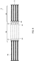
- (A) to (D) of FIG. 8 are schematic views showing the state of irradiating the analysis chip 3A with light emitted from the light source units 12a and 12b of the analysis device 1 and detecting the reactions in the reaction flow channels by the detection units 14 of the analysis device 1 after the analysis chip 3A has set in the analysis device 1.
- While (A) to (D) of FIG. 8 are plan views showing the state where the analysis chip 3A is set in the analysis device 1, in order to make the state of light irradiation clearly understandable, the top surface of the analysis device is not shown and the top surface of the analysis chip 3A is exposed.
- the analysis device 1 and the analysis chip 3A including a reaction system (reaction solution) obtained by mixing a sample and a reagent are prepared in the manner as described above. Then, as shown in (B) and (C) of FIG. 7 , the analysis chip 3A is inserted into the analysis device 1 in the direction of the arrow shown in (A) of FIG. 7 .
- the analysis chip 3A is heated by the heating unit 13 of the analysis device 1 to cause the sample and the reagent to react with each other in each of the reaction flow channels 31A to 36A.
- the reaction includes a nucleic acid amplification reaction using a primer, for example.
- the nucleic acid amplification reaction is not limited to a particular type, and examples of the nucleic acid amplification reaction include the PCR method, TMA method, NASBA method, LAMP method, ICAN method, RCA method, SDA method, HDA method, and SmartAmp method. Among them, an isothermal amplification method such as the SmartAmp method is preferable because it allows treatment at a constant temperature.
- the analysis chip 3A set in the analysis device 1 as shown in (A) of FIG. 8 is irradiated with linear light emitted from the light source unit 12a in the direction of arrow A as shown in (B) of FIG. 8 .
- the linear light emitted from the light source unit 12a is converted into surface light, and the parallel surface at the upper side of the analysis chip 3A is irradiated with the surface light as shown in (C) of FIG. 8 .
- linear light is also emitted from the light source unit 12b in the same manner, the light is converted into surface light, and the parallel surface at the lower side of the analysis chip 3A is irradiated with the converted surface light.
- each of the detection units 14 detects the reaction of a corresponding reaction flow channel (correspondence relationship is indicated by the arrow).
- the detection results obtained by the detection units 14 may be displayed on the analysis device 1 or on an external indicator (e.g., a personal computer, a cellular phone, a smartphone, a tablet, or the like) connected to the analysis device, for example.
- FIG. 9 is a plan view schematically showing an example of the analysis chip of the present invention.
- an analysis chip 9 includes a sample adding unit 9B and a reaction detection unit 9A each composed of a parallel flow channel, and a pair of parallel pistons 4B and 4A corresponding to the sample adding unit 9B and the reaction detection unit 9A.
- the sample adding unit 9B is in communication and is formed in one piece with the reaction detection unit 9A.
- Each flow channel of the sample adding unit 9B includes a sample feeding port 91 at one end, and a primer is disposed inside each flow channel at the other end as a reagent 92.
- a transparent lens-like movable piece 95 is disposed inside each flow channel of the reaction detection unit 9A.
- the line 93 indicates the upper limit of the amount of a sample to be added from the sample feeding port 91
- the line 94 indicates a stop line at the time of inserting the parallel piston 4B into the sample adding unit 9B.
- a dropper 100 including a nozzle is prepared.
- a pretreated specimen and some of reagents for amplification e.g. reaction buffer, enzyme, and the like
- the mixed sample is injected to the sample feeding port 91 of the analysis chip 9 using the dropper 100.
- the mixed sample is injected to the line 93 of the sample adding unit 9B of the analysis chip 9.
- the sample feeding port 91 of the analysis chip 9 is sealed with a sticker 101, and then the parallel pistons 4A and 4B are pushed alternately to further mix the mixed sample and the primer in the analysis chip 9, thereby preparing a reaction solution.
- the movable piece 95 of the reaction detection unit 9A of the analysis chip 9 is moved in response to the movement of the parallel piston 4A.
- the parallel piston 4B is pushed to the line 94, and the parallel piston 4A is taken out. At this time, the movable piece 95 is stopped at the end of the reaction detection unit 9A.
- the reaction detection unit 9A of the analysis chip 9 is inserted into the analysis device 1 including a USB connector 102. Then, using the analysis device 1, the reaction detection unit 9A is heated to carry out a reaction, and the reaction is detected by a detection unit (not shown).
- an analysis device can be downsized.
- the present invention allows, for example, an analyst to analyze a target in a sample easily by preliminarily mixing a sample and a reagent using the reaction system preparation chip of the present invention to prepare a reaction system, separating the analysis chip of the present invention from the reaction system preparation chip, and simply inserting the analysis chip into the analysis device of the present invention.
- viral infection due to an influenza virus and the like and sexually transmitted diseases such as HIV, chlamydia, and the like can be analyzed easily.
- the present invention allows an analyst to analyze a target easily by himself/herself without going to an inspection agency such as a hospital or the like, for example, because the analysis device can be downsized.
Landscapes
- Chemical & Material Sciences (AREA)
- Health & Medical Sciences (AREA)
- Life Sciences & Earth Sciences (AREA)
- Organic Chemistry (AREA)
- Engineering & Computer Science (AREA)
- General Health & Medical Sciences (AREA)
- Zoology (AREA)
- Wood Science & Technology (AREA)
- Biochemistry (AREA)
- Bioinformatics & Cheminformatics (AREA)
- Analytical Chemistry (AREA)
- Biotechnology (AREA)
- Immunology (AREA)
- Chemical Kinetics & Catalysis (AREA)
- Genetics & Genomics (AREA)
- General Engineering & Computer Science (AREA)
- Physics & Mathematics (AREA)
- Proteomics, Peptides & Aminoacids (AREA)
- Microbiology (AREA)
- Clinical Laboratory Science (AREA)
- Molecular Biology (AREA)
- Dispersion Chemistry (AREA)
- Sustainable Development (AREA)
- Biophysics (AREA)
- Pathology (AREA)
- General Physics & Mathematics (AREA)
- Biomedical Technology (AREA)
- Hematology (AREA)
- Medicinal Chemistry (AREA)
- Virology (AREA)
- Automatic Analysis And Handling Materials Therefor (AREA)
- Apparatus Associated With Microorganisms And Enzymes (AREA)
- Investigating Or Analysing Materials By The Use Of Chemical Reactions (AREA)
- Measuring Or Testing Involving Enzymes Or Micro-Organisms (AREA)
- Optical Measuring Cells (AREA)
Applications Claiming Priority (2)
| Application Number | Priority Date | Filing Date | Title |
|---|---|---|---|
| JP2015014849 | 2015-01-28 | ||
| PCT/JP2016/052530 WO2016121886A1 (fr) | 2015-01-28 | 2016-01-28 | Dispositif d'analyse, puce d'analyse, kit d'analyse, et procédé d'analyse les utilisant |
Publications (2)
| Publication Number | Publication Date |
|---|---|
| EP3144380A1 true EP3144380A1 (fr) | 2017-03-22 |
| EP3144380A4 EP3144380A4 (fr) | 2018-04-25 |
Family
ID=56543491
Family Applications (1)
| Application Number | Title | Priority Date | Filing Date |
|---|---|---|---|
| EP16743489.3A Withdrawn EP3144380A4 (fr) | 2015-01-28 | 2016-01-28 | Dispositif d'analyse, puce d'analyse, kit d'analyse, et procédé d'analyse les utilisant |
Country Status (5)
| Country | Link |
|---|---|
| US (1) | US20170197216A1 (fr) |
| EP (1) | EP3144380A4 (fr) |
| JP (1) | JPWO2016121886A1 (fr) |
| RU (1) | RU2016151351A (fr) |
| WO (1) | WO2016121886A1 (fr) |
Families Citing this family (4)
| Publication number | Priority date | Publication date | Assignee | Title |
|---|---|---|---|---|
| JP6759841B2 (ja) * | 2016-08-15 | 2020-09-23 | 住友ゴム工業株式会社 | マイクロ流路チップ |
| GB201615320D0 (en) * | 2016-09-09 | 2016-10-26 | Invitron Ltd | Point of care platform test |
| EP3572498A4 (fr) * | 2017-01-18 | 2020-11-18 | Shinko Chemical Co., Ltd. | Dispositif d'évaluation de substances chimiques et méthode d'évaluation de substances chimiques |
| CN112834497B (zh) * | 2021-02-22 | 2025-03-18 | 杉木(深圳)生物科技有限公司 | 微流控芯片、尿液分析方法及装置、马桶 |
Family Cites Families (20)
| Publication number | Priority date | Publication date | Assignee | Title |
|---|---|---|---|---|
| US6977145B2 (en) * | 1999-07-28 | 2005-12-20 | Serono Genetics Institute S.A. | Method for carrying out a biochemical protocol in continuous flow in a microreactor |
| JP2004208512A (ja) * | 2002-12-27 | 2004-07-29 | Asahi Kasei Corp | 核酸検出用カートリッジ |
| JP2004305009A (ja) * | 2003-04-02 | 2004-11-04 | Hitachi Ltd | 核酸増幅装置及び核酸増幅方法 |
| FR2857099B1 (fr) * | 2003-07-04 | 2005-10-07 | Jean Marie Billiotte | Procede et dispositif d'analyse chimique ou biologique par senseur a chambre monolithique en gerbe multi-micro-tubulaire et transducteur lateral de mesure integrale |
| JP2012085659A (ja) * | 2004-05-02 | 2012-05-10 | Fluidigm Corp | 熱反応デバイスおよびその熱反応デバイスの使用方法 |
| WO2006106643A1 (fr) * | 2005-04-01 | 2006-10-12 | Konica Minolta Medical & Graphic, Inc. | Micro système d’analyse globale, puce d’examen et procédé d’examen |
| EP1910688A4 (fr) * | 2005-08-04 | 2010-03-03 | Helicos Biosciences Corp | Cellules a circulation multicanaux |
| JP4519794B2 (ja) * | 2006-03-16 | 2010-08-04 | 日本電信電話株式会社 | マイクロ流路素子 |
| WO2008005241A2 (fr) * | 2006-06-30 | 2008-01-10 | Canon U.S. Life Sciences, Inc. | Systèmes et procédés servant à suivre l'amplification et le comportement de dissociation de molécules d'adn |
| JP2008148690A (ja) * | 2006-11-22 | 2008-07-03 | Fujifilm Corp | マイクロチップを用いた核酸増幅方法およびマイクロチップ、それを用いた核酸増幅システム |
| CN101541962A (zh) * | 2007-03-23 | 2009-09-23 | 株式会社东芝 | 核酸检测盒以及核酸检测装置 |
| US8105783B2 (en) * | 2007-07-13 | 2012-01-31 | Handylab, Inc. | Microfluidic cartridge |
| CN101910399B (zh) * | 2007-10-30 | 2015-11-25 | 考利达基因组股份有限公司 | 用于核酸高通量测序的装置 |
| JP2009268432A (ja) * | 2008-05-09 | 2009-11-19 | Canon Inc | 標的核酸の測定方法 |
| JP5268444B2 (ja) * | 2008-06-23 | 2013-08-21 | 株式会社日立ハイテクノロジーズ | 単分子リアルタイムシーケンス装置,核酸分析装置及び単分子リアルタイムシーケンス方法 |
| EP4512526A3 (fr) * | 2008-09-23 | 2025-06-04 | Bio-Rad Laboratories, Inc. | Système de dosage à base de gouttelettes |
| EP2391883B1 (fr) * | 2009-01-30 | 2018-03-07 | Micronics, Inc. | Système portable de détection de fluorescence à gain élevé |
| CA3016967C (fr) * | 2010-04-16 | 2021-08-31 | Opko Diagnostics, Llc | Systemes et appareils d'analyse d'echantillons |
| US20110312537A1 (en) * | 2010-06-17 | 2011-12-22 | Geneasys Pty Ltd | Loc device for amplifying and detecting target nucleic acid sequences using electrochemiluminescent resonant energy transfer, linear probes with covalently attached primers |
| JP6068227B2 (ja) * | 2013-03-29 | 2017-01-25 | 株式会社日立ハイテクノロジーズ | 核酸分析装置 |
-
2016
- 2016-01-28 RU RU2016151351A patent/RU2016151351A/ru not_active Application Discontinuation
- 2016-01-28 JP JP2016572154A patent/JPWO2016121886A1/ja not_active Withdrawn
- 2016-01-28 EP EP16743489.3A patent/EP3144380A4/fr not_active Withdrawn
- 2016-01-28 US US15/314,373 patent/US20170197216A1/en not_active Abandoned
- 2016-01-28 WO PCT/JP2016/052530 patent/WO2016121886A1/fr not_active Ceased
Also Published As
| Publication number | Publication date |
|---|---|
| US20170197216A1 (en) | 2017-07-13 |
| JPWO2016121886A1 (ja) | 2017-11-02 |
| RU2016151351A (ru) | 2019-02-28 |
| EP3144380A4 (fr) | 2018-04-25 |
| RU2016151351A3 (fr) | 2019-06-11 |
| WO2016121886A1 (fr) | 2016-08-04 |
Similar Documents
| Publication | Publication Date | Title |
|---|---|---|
| US10315195B2 (en) | Device, system and method processing a sample | |
| US20090061450A1 (en) | System and method for diagnosis of infectious diseases | |
| AU2014298179B2 (en) | Fluidic cartridge for nucleic acid amplification and detection | |
| ES2635330T3 (es) | Un cartucho de fluido y un procedimiento para procesar una muestra de liquido | |
| WO2007106552A2 (fr) | Systeme et procede de diagnostic de maladies infectieuses | |
| EP3495824A1 (fr) | Cellule d'analyse, dispositif d'analyse, équipement d'analyse et système d'analyse | |
| BRPI0717552A2 (pt) | Sistema de cartucho, método para formar um cartucho, cartucho, sistema de ensaio, método de análise para um ou mais analitos em uma amostra, componente de reagente para armazenar um ou mais reagentes, e, uso de um sistema de cartucho, cartucho, sistema de ensaio e/ou componente de reagente | |
| CN110325652A (zh) | 使用流动池检测分子的装置和方法 | |
| BR112012021202B1 (pt) | aparelho e métodos para preparação, reação e detecção integradas de amostras | |
| KR20170024827A (ko) | 미세유로 필름 반응기, 핵산 추출 모듈 및 qPCR 반응조성물 모듈이 구비된 qPCR 카트리지 및 이를 이용한 고속 qPCR 시스템 | |
| EP2705130A2 (fr) | Appareil et procédé pour la préparation, la réaction et la détection intégrées d'échantillons | |
| CN107083319A (zh) | 具有集成传送模块的测试盒 | |
| EP3144380A1 (fr) | Dispositif d'analyse, puce d'analyse, kit d'analyse, et procédé d'analyse les utilisant | |
| EP3327444A1 (fr) | Kit d'analyse et procédé d'analyse l'utilisant | |
| KR20240053619A (ko) | 샘플 테스트를 위해 밀봉부를 피어싱하는 방법 | |
| EP1371419A1 (fr) | Procédé et dispositif pour détecter la présence d'un analyte dans un échantillon | |
| CN107683330A (zh) | 用于样品收集的装置和方法 | |
| WO2025056079A1 (fr) | Amorce pour la détection de micro-organismes pathogènes utilisant le système rpa-crispr/cas12a et utilisation de l'amorce | |
| WO2025103360A1 (fr) | Puce microfluidique capable de commuter de façon flexible de multiples échantillons et de multiples indicateurs en quantité, et système de détection intelligent | |
| CN104946505A (zh) | 实现pcr的微流控芯片及实时pcr的病毒快速检测装置 | |
| US20180282794A1 (en) | Sample Preparation Vessels, Microfluidic Circuits, and Systems and Methods for Sample Preparation, Extraction, and Analysis | |
| KR20240045179A (ko) | 챔버 밀폐가 가능한 타깃 분석물 검출 카트리지 | |
| US20230256432A1 (en) | Nucleic acid extraction container and nucleic acid extraction method | |
| IT201900012345A1 (it) | Dispositivo diagnostico e suoi usi | |
| US20260092319A1 (en) | Rotatable discs and systems and methods for sample analysis |
Legal Events
| Date | Code | Title | Description |
|---|---|---|---|
| STAA | Information on the status of an ep patent application or granted ep patent |
Free format text: STATUS: THE INTERNATIONAL PUBLICATION HAS BEEN MADE |
|
| PUAI | Public reference made under article 153(3) epc to a published international application that has entered the european phase |
Free format text: ORIGINAL CODE: 0009012 |
|
| STAA | Information on the status of an ep patent application or granted ep patent |
Free format text: STATUS: REQUEST FOR EXAMINATION WAS MADE |
|
| 17P | Request for examination filed |
Effective date: 20161216 |
|
| AK | Designated contracting states |
Kind code of ref document: A1 Designated state(s): AL AT BE BG CH CY CZ DE DK EE ES FI FR GB GR HR HU IE IS IT LI LT LU LV MC MK MT NL NO PL PT RO RS SE SI SK SM TR |
|
| AX | Request for extension of the european patent |
Extension state: BA ME |
|
| RIC1 | Information provided on ipc code assigned before grant |
Ipc: G01N 37/00 20060101ALI20171214BHEP Ipc: B01L 7/00 20060101ALI20171214BHEP Ipc: C12Q 1/68 20180101ALI20171214BHEP Ipc: G01N 35/08 20060101ALI20171214BHEP Ipc: C12M 1/34 20060101AFI20171214BHEP Ipc: C12M 1/00 20060101ALI20171214BHEP |
|
| A4 | Supplementary search report drawn up and despatched |
Effective date: 20180327 |
|
| RIC1 | Information provided on ipc code assigned before grant |
Ipc: C12M 1/34 20060101AFI20180321BHEP Ipc: B01L 7/00 20060101ALI20180321BHEP Ipc: G01N 37/00 20060101ALI20180321BHEP Ipc: C12Q 1/68 20060101ALI20180321BHEP Ipc: G01N 35/08 20060101ALI20180321BHEP Ipc: C12M 1/00 20060101ALI20180321BHEP |
|
| DAV | Request for validation of the european patent (deleted) | ||
| DAX | Request for extension of the european patent (deleted) | ||
| STAA | Information on the status of an ep patent application or granted ep patent |
Free format text: STATUS: EXAMINATION IS IN PROGRESS |
|
| 17Q | First examination report despatched |
Effective date: 20181123 |
|
| STAA | Information on the status of an ep patent application or granted ep patent |
Free format text: STATUS: THE APPLICATION IS DEEMED TO BE WITHDRAWN |
|
| 18D | Application deemed to be withdrawn |
Effective date: 20191001 |