EP3144436B1 - Procede et systeme de fonctionnement d'un dispositif sanitaire - Google Patents
Procede et systeme de fonctionnement d'un dispositif sanitaire Download PDFInfo
- Publication number
- EP3144436B1 EP3144436B1 EP16001893.3A EP16001893A EP3144436B1 EP 3144436 B1 EP3144436 B1 EP 3144436B1 EP 16001893 A EP16001893 A EP 16001893A EP 3144436 B1 EP3144436 B1 EP 3144436B1
- Authority
- EP
- European Patent Office
- Prior art keywords
- sanitary
- sanitary device
- sensor device
- zones
- sensor
- Prior art date
- Legal status (The legal status is an assumption and is not a legal conclusion. Google has not performed a legal analysis and makes no representation as to the accuracy of the status listed.)
- Active
Links
Images


Classifications
-
- G—PHYSICS
- G05—CONTROLLING; REGULATING
- G05B—CONTROL OR REGULATING SYSTEMS IN GENERAL; FUNCTIONAL ELEMENTS OF SUCH SYSTEMS; MONITORING OR TESTING ARRANGEMENTS FOR SUCH SYSTEMS OR ELEMENTS
- G05B15/00—Systems controlled by a computer
- G05B15/02—Systems controlled by a computer electric
-
- A—HUMAN NECESSITIES
- A47—FURNITURE; DOMESTIC ARTICLES OR APPLIANCES; COFFEE MILLS; SPICE MILLS; SUCTION CLEANERS IN GENERAL
- A47K—SANITARY EQUIPMENT; ACCESSORIES THEREFOR, e.g. TOILET ACCESSORIES
- A47K3/00—Baths; Showers; Appurtenances therefor
- A47K3/28—Showers or bathing douches
- A47K3/281—Accessories for showers or bathing douches, e.g. cleaning devices for walls or floors of showers
-
- E—FIXED CONSTRUCTIONS
- E03—WATER SUPPLY; SEWERAGE
- E03C—DOMESTIC PLUMBING INSTALLATIONS FOR FRESH WATER OR WASTE WATER; SINKS
- E03C1/00—Domestic plumbing installations for fresh water or waste water; Sinks
- E03C1/02—Plumbing installations for fresh water
- E03C1/05—Arrangements of devices on wash-basins, baths, sinks, or the like for remote control of taps
- E03C1/055—Electrical control devices, e.g. with push buttons, control panels or the like
- E03C1/057—Electrical control devices, e.g. with push buttons, control panels or the like touchless, i.e. using sensors
-
- E—FIXED CONSTRUCTIONS
- E03—WATER SUPPLY; SEWERAGE
- E03C—DOMESTIC PLUMBING INSTALLATIONS FOR FRESH WATER OR WASTE WATER; SINKS
- E03C1/00—Domestic plumbing installations for fresh water or waste water; Sinks
- E03C1/12—Plumbing installations for waste water; Basins or fountains connected thereto; Sinks
- E03C1/18—Sinks, whether or not connected to the waste-pipe
-
- E—FIXED CONSTRUCTIONS
- E03—WATER SUPPLY; SEWERAGE
- E03D—WATER-CLOSETS OR URINALS WITH FLUSHING DEVICES; FLUSHING VALVES THEREFOR
- E03D13/00—Urinals ; Means for connecting the urinal to the flushing pipe and the wastepipe; Splashing shields for urinals
- E03D13/005—Accessories specially adapted for urinals
-
- E—FIXED CONSTRUCTIONS
- E03—WATER SUPPLY; SEWERAGE
- E03D—WATER-CLOSETS OR URINALS WITH FLUSHING DEVICES; FLUSHING VALVES THEREFOR
- E03D5/00—Special constructions of flushing devices, e.g. closed flushing system
- E03D5/10—Special constructions of flushing devices, e.g. closed flushing system operated electrically, e.g. by a photo-cell; also combined with devices for opening or closing shutters in the bowl outlet and/or with devices for raising/or lowering seat and cover and/or for swiveling the bowl
- E03D5/105—Special constructions of flushing devices, e.g. closed flushing system operated electrically, e.g. by a photo-cell; also combined with devices for opening or closing shutters in the bowl outlet and/or with devices for raising/or lowering seat and cover and/or for swiveling the bowl touchless, e.g. using sensors
-
- E—FIXED CONSTRUCTIONS
- E03—WATER SUPPLY; SEWERAGE
- E03D—WATER-CLOSETS OR URINALS WITH FLUSHING DEVICES; FLUSHING VALVES THEREFOR
- E03D9/00—Sanitary or other accessories for lavatories ; Devices for cleaning or disinfecting the toilet room or the toilet bowl; Devices for eliminating smells
Definitions
- the present invention relates to a method for operating a sanitary device and an arrangement comprising at least one sensor device and one sanitary device.
- a method and an arrangement are described with which an automatic or demand-oriented operation of the sanitary facility is made possible, in particular the initiation of actions preceding and / or after the use of the sanitary facility.
- sanitary facilities increasingly wants additional functions or actions in sanitary facilities to be carried out completely independently before and / or after the actual use.
- a water closet it may be desirable for the lid to be raised, for the seat cover to be preheated and / or disinfected, or for cleaning to be carried out.
- showers it may be desirable that the jet nozzle, the shape of the jet, the lighting in the shower cubicle, the underfloor heating, etc. are operated as required and are therefore energy and water-saving.
- a washstand for example, it is desired that it is automatically recognized which water connection is selected from a plurality of water connections for contactless operation.
- a urinal There is also a similar requirement with regard to a urinal, as has already been described in connection with the water closet.
- the WO 99/04283 A describes a system for controlling a sanitary fitting with a plurality of sensors, each provided with a receiver and a controller and coupled in such a way that a control signal can be generated in response to the received signals.
- a method for controlling sanitary fittings is described, wherein actuators of the sanitary fittings selected by a central controller are operated on the basis of detection signals from the sensors.
- the US2015020299A1 relates to an intelligent toilet with multiple detection fields, which are formed with two or more electrical fields with capacitive proximity detection.
- a flushing control unit of the toilet which receives proximity capacity detection information, can control the bowl area flushing according to one or more logic operations.
- Sensor elements that can trigger a part of this function independently have already been proposed for the execution of such functions or actions by the sanitary device without specific cooperation by the user, such as the actuation of buttons.
- distance sensors, touch sensors and / or motion sensors have been presented.
- a disadvantage of these sensors, however, is that they often only provide binary signals, ie either the "on” state or the "off” state. In other words, in order to be able to fully control the sanitary facilities shown above, complicated, sometimes unnatural or uncomfortable operating concepts must be implemented and / or a large number of sensors must be used.
- a method for operating a sanitary facility is to be specified, with a less technical effort, possibly avoiding special negative environmental influences, making it possible to perform these "service functions" in sanitary facilities as required and / or automatically.
- the arrangement for this purpose should be particularly set up, so that in particular also with regard to the simplest possible technical structure and a robust signal evaluation should be ensured.
- a method for operating a sanitary device with at least one sensor device contributes to achieving the above-mentioned object, the sanitary device having a control unit for setting at least one actuator of the sanitary device, the sensor device having a measuring unit for determining environmental situations of the sanitary device, the measuring unit is connected in a data-conducting manner to the control unit, the sensor device comprising a plurality of infrared LED light emitters, which can separately reach several zones in the vicinity of the sanitary device, and at least one light receiver.
- the object of the method is in particular to carry out actions independently or automatically before, during and / or after the actual use of the sanitary facility.
- a so-called environmental analysis is preferably carried out in accordance with step a).
- the surrounding area in or around the sanitary facility is divided into several zones, which can then be monitored independently.
- the zones are, in particular, those flat or spatial areas of the environment that can be detected by sensors, in particular by separate or separately responsible sensor units of a sensor device. It is essential that a plurality of zones is set up in a near surrounding area of the sanitary facility and in a far surrounding area of the sanitary facility. For example, at least 2, 3 or 4 zones, preferably at least 12 zones or even more zones, can be set up.
- half of the zones relate to the near surrounding area and the other half to the far surrounding area.
- the setting of the zones can be set taking into account the surroundings of the sanitary device and / or can be predetermined by the structure of the sensor device.
- the zones are freely configurable and can overlap if necessary.
- step b) the current environmental situation is now detected by means of a sensor device.
- a sensor device This includes, in particular, that each of the several zones is individually sensed by means of the sensor device.
- This serves in particular the purpose of determining malfunctions and / or recording to what extent the sensor-sensed environment of the sanitary facility or the several zones are not fully accessible due to structural conditions (wall projections, furniture, windows, sloping ceilings, curtains, etc.).
- step b) it is also possible for step b) to be carried out several times in order to obtain security about the current environmental situation (without users).
- Step c) has the result that the so-called standard environmental situation is determined.
- this standard environmental situation is used for later comparisons and / or Basis for the subsequent evaluation saved by the sensor device. This now clarifies which zones can be passed through freely and to what extent for a user, or which standard measured values are to be recorded by the sensor device if the sanitary device is not to be used.
- this preparatory and / or checking process comprises steps a), b) and c)
- the actual monitoring period can begin.
- the sensor device is now used to monitor the several zones.
- the main objective of the monitoring is that changes within the several zones lead to changed measurement results, which can then be analyzed and evaluated.
- the sensor device is thus active during step d).
- step e a predetermined action of the sanitary device can be triggered (step e)).
- a change in the environmental situation is "characterizable" in particular when the sensor device or measuring units or control units in contact with it are able to assign the identified measured values to a specific behavior of the user, so that an action which may have been specifically selected for this purpose is carried out.
- step c) it can be determined where an entrance door and the sanitary facility itself are located with regard to this sanitary facility or the sanitary facility.
- step d) If it follows from the monitoring according to step d) that an object is moving from the entrance door to the sanitary facility, it can be concluded that the sanitary facility will soon be used, so that, for example, a toilet lid is raised and / or a preliminary cleaning is carried out. If, for example, a user accesses the toilet paper, this can also be characterized and a further action by the sanitary facility, for example a cleaning process and / or an odor extraction, can be initiated.
- a further action by the sanitary facility for example a cleaning process and / or an odor extraction
- an immediate interpretation of the detected change in the environmental situation takes place on the basis of predetermined change schemes or learned in the course of operating the sanitary device.
- the specified change schemes can also be learned on site.
- the user can specify motion sequences and / or gestures in a "learning mode" of the sensor device, which are then available for selection in later actual operation of the sanitary device.
- this also means in particular that the change in the environmental situation detected by the sensor device is tracked or interpreted and is compared in terms of measurement technology with various stored or previously known change schemes. If there is sufficient correspondence here, a specific (already saved or retrievable) change scheme is selected and the action to actuate the sanitary facility, which is also filed or held, is carried out.
- the operation of the sanitary facility does not have to be a single action, but may also include several, in particular timed, actions. It is also important that the monitoring scheme of the sensor device is then adapted as a function of the selected and suitable change scheme, in particular if it is expected that the user will then behave in a predetermined manner.
- step b) and in step d) a plurality of zones with sensor units of the sensor device respectively assigned be scanned.
- the sensor assemblies work without contact and a sensor assembly is specifically assigned to only a part of the actually provided multiple zones.
- a sensor unit monitors or scans a zone, two zones or a maximum of three zones. In this respect, a zone-specific analysis of the environmental situation of the sanitary facility can take place.
- zones be scanned with the sensor device at different times.
- the respective responsible sensor units can be triggered at different times, so that the levels are monitored or scanned zone by zone, in particular from one zone to the adjacent zone.
- the order or frequency of the acquisition of measurement data within a zone or from adjacent zones can then be adjusted if a corresponding change is currently given in specific zones. This method is particularly useful when the sensor units access a common receiver or a common measuring unit.
- the characterizable change is a movement or gesture by a user of the sanitary facility.
- a “movement” of the user is understood here to mean the sequence of movements customary for the use of the sanitary facility. This applies, for example, to running towards or into the sanitary facility, reaching for accessories (soap dispenser, dryer, light switch, etc.) and / or the user staying at a predetermined position in the vicinity of the sanitary facility.
- a “gesture” of the user is understood to mean, for example, a predefined posture of the user, for example the arms or hands of the user, which is concrete are specified. In this way, individual commands can be recognized, for example by gestures, or a selection made from an operating menu. The gestures can be defined within a zone or across zones.
- step d) includes the activation of an actuator for moving a component of the sanitary device.
- the actuator can be mechanical and / or electronic.
- components for supplying or dispensing fluids by means of the sanitary device are considered as components (such as valves, thermostats, heating devices, jet formers, etc.), but also external components that enable or support the use.
- Such external components can be ventilation, heating, a lid, a flap or the like.
- steps b) and c) are repeated intermittently and step d) is carried out more frequently or continuously.
- the monitoring of the multiple zones is preferably carried out continuously or significantly more frequently, for example several times per minute or even several times per second. It is also possible that it is necessary to initiate step d) beforehand, for example when the light in the room is switched on or when a door is opened, from which it can be seen that use of the sanitary facility could only now be imminent.
- an arrangement which comprises at least one sensor device and one sanitary device.
- the sanitary device has a control unit for setting (or regulating) at least one actuator of the sanitary device.
- the sensor device has a measuring unit for determining environmental situations of the sanitary device.
- the measuring unit is also connected to the control unit (electronically or electrically) in a data-conducting manner.
- the arrangement is suitable and set up to carry out the method presented here. With this arrangement, there is in particular a (spatial) separation of the evaluation of the signals of the sensor device. While measuring or electronic conversion of measured values takes place within the sensor device by means of the measuring unit, these measured data are then passed on to a control unit, which is preferably part of the sanitary device itself.
- Step e) is carried out in particular in the control device, the sub-processes i., Ii., And iii. preferably be carried out.
- the measurement values are then analyzed or interpreted in the control unit of the sanitary facility.
- the control unit can be an element of the individual sanitary facility or also a higher-level control unit for using or operating a number of sanitary facilities.
- the sensor device has a plurality of light emitters, which can separately reach several zones in the vicinity of the sanitary device, and at least one light receiver. Consequently, it is very particularly preferred that a light emitter is responsible for one or more zones and can reach them (alone or separately).
- a (single) light receiver is then provided, which the reflective Can then absorb and process light rays from the area surrounding the sanitary facility.
- the sensor device comprises infrared LED as a light emitter.
- the sensor device is in particular set up on the basis of measuring the transit time of light pulses, in particular light from light-emitting diodes (LED) in the visible or infrared spectrum, the position of users or objects in the vicinity of the sanitary device and preferably also their distance from the sanitary device or the sensor device to determine.
- the LEDs preferably generate an expanding or diffuse light beam that covers a wider area (a zone) of the surroundings.
- the light receiver detects the light components scattered back by the objects or the user in the beam of the LED and independently analyzes their signal form.
- the distance or the type of movement is determined on the basis of the duration that the light beam takes to return from the respective object or the user to the light receiver (transit time).
- the LEDs are used in particular to generate very short light signals, typically 100,000 pulses per second.
- the so-called "time-of-flight” principle essentially consists of measuring the time that a light pulse takes to get from the light emitter to an object or a user of the sanitary facility and from there back to the light receiver (round trip time).
- c the speed of light in a vacuum
- n the refractive index of the medium (air) in which the light pulse spreads).
- Absorption, total reflection or diffuse (scattered) reflection of the emitted light there are: Absorption, total reflection or diffuse (scattered) reflection of the emitted light.
- the echo pulse arrives at the light receiver with different intensity, which is measured there.
- the measured intensity is therefore dependent on the measured distance and the angle of incidence, which can be determined with the aid of an image-capturing optical system that focuses the reflecting light beam.
- the zone or the beam width can in particular be selected with the following angular ranges starting from a central point in the vicinity of the sanitary device: 3 °, 9 °, 18 °, 24 ° , 34 °.
- This solution is used particularly in a sanitary facility that is selected from the following group: water closet, shower, washstand, urinal.
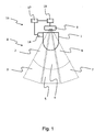
- Fig. 1 shows an arrangement 16 for carrying out an operating method of a sanitary device 1 explained here.
- the sanitary device 1 is shown here in the manner of a water closet, but the principle illustrated can equally be transferred to a shower, a washstand and / or a urinal without the need for the sanitary specialist mentioned here, special additional supplements are required.
- a (central) sensor device 9, which comprises a measuring unit 18, is provided above the sanitary device 1.
- the measuring unit 18 can comprise, for example, a microprocessor or an electronic data processing unit.
- the measuring unit 18 is connected in a data-conducting manner to a control unit 17 which is connected to an actuator 14 of the sanitary device 1.
- the latter connection can in turn be electrical in nature, but a mechanical coupling would also be possible.
- the control unit 17 can comprise, for example, a microprocessor or an electronic data processing unit.
- Component 15 can be, for example, a heating element for the water closet and / or lid opening device.
- a plurality of zones can be detected by sensor or measurement technology by means of the sensor device 9.
- the sensor device 9 of the arrangement 16 is designed in such a way that these form three essentially opening zones, each of which is subdivided into a near area and a far area.
- Fig. 1 Shown on the left is a first near zone 2 and a first distant zone 3. Adjacent to this and in the central area a second near zone 4 and a second distant zone 5 are formed.
- the monitoring area again closes with a third near zone 6 and a third distant zone 7.
- the sensor device 9 is now set up and equipped such that it detects objects / users or movements within these zones 2, 3, 4, 5, 6 , 7 can determine or record.
- Fig. 2 a special situation is now shown during use.
- the arrangement 16 is equipped with a sensor device 9 which has a separate sensor unit for each zone region.
- a first sensor assembly 10 is provided for the first near / distant zone, a second sensor assembly 11 for the second near / distant zone and a third sensor assembly 12 for the third near / distant zone.
- These monitor their zones independently and independently of one another.
- an object 23 is placed in the area of the first removed zone 3. This is, for example, a cabinet in the bathroom, which is immovable and at least immovably placed there for a longer period of time. In steps a), b) and c), this is determined to be an unchangeable object and is therefore not taken into account for the subsequent evaluation or monitoring in accordance with steps d) and e). In other words, this object 23 is switched "blind".
- measuring unit 18 realizes a characteristic change in the environmental situation (step d)). Proceeding from this, it compares the detected change in the environmental situation with a predefined change scheme, for example stored in the control unit 17, the appropriate change scheme then being selected and an action to be carried out depending on the identified change scheme, for example lifting the lid.
- a predefined change scheme for example stored in the control unit 17, the appropriate change scheme then being selected and an action to be carried out depending on the identified change scheme, for example lifting the lid.
- Fig. 3 illustrates in particular the situation that the zones can be designed not only horizontally but also, if necessary, vertically.
- the sensor device comprises a plurality of light emitters (first light emitter 19, second light emitter 20, third light emitter 21) and a common light receiver 22.
- measuring unit 18 and control unit 17 interact directly with one another, for example on a common data processing system.
- the actuation of actuators 14 by the control unit 17 can then take place as required on the different components 15 of the sanitary device 1.
- a valve for flushing, energizing the electric seat heating, initiating air extraction, triggering fragrances, sending entertainment information, etc. can take place automatically.
Landscapes
- Public Health (AREA)
- Health & Medical Sciences (AREA)
- Engineering & Computer Science (AREA)
- Water Supply & Treatment (AREA)
- Life Sciences & Earth Sciences (AREA)
- Hydrology & Water Resources (AREA)
- Epidemiology (AREA)
- General Health & Medical Sciences (AREA)
- Aviation & Aerospace Engineering (AREA)
- Environmental & Geological Engineering (AREA)
- General Engineering & Computer Science (AREA)
- Physics & Mathematics (AREA)
- General Physics & Mathematics (AREA)
- Automation & Control Theory (AREA)
- Bidet-Like Cleaning Device And Other Flush Toilet Accessories (AREA)
- Domestic Plumbing Installations (AREA)
Claims (8)
- Procédé, destiné à faire fonctionner un dispositif sanitaire (1) pourvu d'au moins un dispositif de capteurs (9), le dispositif sanitaire (1) ayant une unité de contrôle (17) destinée au réglage d'au moins un actionneur (14) du dispositif sanitaire (1), le dispositif de capteurs (9) ayant une unité de mesure (18), destinée à évaluer des situations environnantes du dispositif sanitaire (1), l'unité de mesure (18) étant connectée en transmission de données avec l'unité de contrôle (17), le dispositif de capteurs (9) comprenant une pluralité d'émetteurs lumineux (19, 20, 21) à LED infrarouge, susceptible d'atteindre séparément plusieurs zones (2, 3, 4, 5, 6, 7) de l'environnement (8) du dispositif sanitaire (1) et au moins un récepteur lumineux (22), comprenant au moins les étapes suivantes, consistant à :a) déterminer plusieurs zones (2, 3, 4, 5, 6, 7) d'un environnement (8) du dispositif sanitaire (1), dans une région environnante proche du dispositif sanitaire (1) ainsi que dans une région environnante éloignée du dispositif sanitaire (1) étant aménagée respectivement une pluralité de zones, et les zones étant formées d'un faisceau lumineux s'élargissant, qui est généré par la LED infrarouge ;b) détecter une situation environnante actuelle au moyen d'un dispositif de capteurs (9) ;c) déterminer une situation environnante standard ;d) superviser les plusieurs zones (2, 3, 4, 5, 6, 7) au moyen du dispositif de capteurs (9) ;e) déclencher une action du dispositif sanitaire (1), si dans l'étape d), une modification caractéristique de la situation environnante est détectée, l'étape e) comprenant au moins les processus partiels suivants, consistant à :i. comparer la modification détectée de la situation environnante avec des schémas de modifications prédéfinis, appris dans le cadre du fonctionnement du dispositif sanitaire (1) ;ii. sélectionner un schéma de modification adapté mémorisé ou interrogeable ;iii. sélectionner au moins une action destinée à actionner le dispositif sanitaire (1) en fonction du schéma de modification ; etiv. ajuster le schéma de supervision dans l'étape d) en fonction des schémas de modification adaptés sélectionnés si l'on en attend que par la suite, l'utilisateur va se comporter d'une manière prédéfinie.
- Procédé selon la revendication 1, lors duquel dans l'étape b) et dans l'étape d) on numérise plusieurs zones (2, 3, 4, 5, 6, 7) avec des groupes de capteurs (10, 11, 12) respectivement associés du dispositif de capteurs (9).
- Procédé selon la revendication 1 ou 2, lors duquel on numérise avec un décalage dans le temps plusieurs zones (2, 3, 4, 5, 6, 7) avec le dispositif de capteurs (9).
- Procédé selon l'une quelconque des revendications précédentes, lors duquel la modification susceptible d'être caractérisée est un déplacement ou un geste d'un utilisateur (13) du dispositif sanitaire (1).
- Procédé selon l'une quelconque des revendications précédentes, l'étape e) comprenant l'activation d'un actionneur (14) pour le déplacement d'un élément structurel (15) du dispositif sanitaire (1).
- Procédé selon l'une quelconque des revendications précédentes, les étapes b) et c) étant réitérées par intermittence et l'étape d) étant réalisée plus souvent ou en continu.
- Ensemble (16), comprenant au moins un dispositif de capteurs (9) et un dispositif sanitaire (1), le dispositif sanitaire (1) ayant une unité de contrôle (17) pour le réglage d'au moins un actionneur (14) du dispositif sanitaire (1), le dispositif de capteurs (9) ayant une unité de mesure (18) pour déterminer des situations environnantes du dispositif sanitaire (1), l'unité de mesure (18) étant connectée en transmission de données avec l'unité de contrôle (17), le dispositif de capteurs (9) comprenant une pluralité d'émetteurs lumineux (19, 20, 21) à LED infrarouge, susceptible d'atteindre séparément plusieurs zones (2, 3, 4, 5, 6, 7) de l'environnement (8) du dispositif sanitaire (1), et au moins un récepteur lumineux (22), et l'ensemble (16) étant apte à et aménagé pour réaliser un procédé selon l'une quelconque des revendications précédentes .
- Ensemble (16) selon la revendication 7, le dispositif sanitaire (1) étant sélectionné dans le groupe suivant, comprenant : toilettes, douche, lavabo, urinoir.
Applications Claiming Priority (1)
| Application Number | Priority Date | Filing Date | Title |
|---|---|---|---|
| DE102015011386.0A DE102015011386A1 (de) | 2015-09-04 | 2015-09-04 | Verfahren und Anordnung zum Betrieb einer Sanitäreinrichtung |
Publications (2)
| Publication Number | Publication Date |
|---|---|
| EP3144436A1 EP3144436A1 (fr) | 2017-03-22 |
| EP3144436B1 true EP3144436B1 (fr) | 2020-06-10 |
Family
ID=56893643
Family Applications (1)
| Application Number | Title | Priority Date | Filing Date |
|---|---|---|---|
| EP16001893.3A Active EP3144436B1 (fr) | 2015-09-04 | 2016-08-30 | Procede et systeme de fonctionnement d'un dispositif sanitaire |
Country Status (3)
| Country | Link |
|---|---|
| US (1) | US20170068228A1 (fr) |
| EP (1) | EP3144436B1 (fr) |
| DE (1) | DE102015011386A1 (fr) |
Families Citing this family (11)
| Publication number | Priority date | Publication date | Assignee | Title |
|---|---|---|---|---|
| US9032565B2 (en) | 2009-12-16 | 2015-05-19 | Kohler Co. | Touchless faucet assembly and method of operation |
| US10301801B2 (en) | 2014-12-18 | 2019-05-28 | Delta Faucet Company | Faucet including capacitive sensors for hands free fluid flow control |
| US11078652B2 (en) | 2014-12-18 | 2021-08-03 | Delta Faucet Company | Faucet including capacitive sensors for hands free fluid flow control |
| US10527191B2 (en) * | 2015-12-15 | 2020-01-07 | Sdb Ip Holdings, Llc | System, method, and apparatus for monitoring restroom appliances |
| CN109031976A (zh) * | 2018-09-19 | 2018-12-18 | 珠海格力电器股份有限公司 | 一种智能家居系统 |
| TWI724453B (zh) * | 2018-09-19 | 2021-04-11 | 仁寶電腦工業股份有限公司 | 智能衛浴系統及其控制方法 |
| CN109212992A (zh) * | 2018-10-18 | 2019-01-15 | 珠海格力电器股份有限公司 | 一种基于智能马桶的智能家居控制方法与智能马桶 |
| DE102018133312B4 (de) | 2018-12-21 | 2021-08-05 | Irlbacher Blickpunkt Glas Gmbh | Vorrichtung zur abstandsabhängigen Erkennung eines mobilen Objektes sowie Verfahren zu deren Betrieb |
| DE102021117431A1 (de) | 2021-07-06 | 2023-01-12 | Grohe Ag | Sanitärarmatur und Verfahren zur Steuerung einer Sanitärarmatur |
| EP4159939A1 (fr) * | 2021-09-30 | 2023-04-05 | Siemens Mobility GmbH | Véhicule ferroviaire avec dispositif de chasse d'eau |
| US12493355B2 (en) | 2022-04-14 | 2025-12-09 | Kohler Co. | Touchless plumbing control system |
Family Cites Families (13)
| Publication number | Priority date | Publication date | Assignee | Title |
|---|---|---|---|---|
| JP2585087Y2 (ja) * | 1993-10-14 | 1998-11-11 | 宇呂電子工業株式会社 | 自動洗浄装置 |
| US5868311A (en) * | 1997-09-03 | 1999-02-09 | Cretu-Petra; Eugen | Water faucet with touchless controls |
| AU8404398A (en) * | 1997-07-18 | 1999-02-10 | Kohler Company | Advanced touchless plumbing systems |
| DE20014027U1 (de) * | 1999-10-06 | 2000-11-16 | Geberit Technik AG, Jona, St.Gallen | Berührungslose Spüleinrichtung für eine WC-Anlage |
| US6618864B2 (en) * | 2000-04-06 | 2003-09-16 | Bennie N Veal | Automatic flushing and seat raising arrangements for toilets |
| US7107631B2 (en) * | 2000-10-03 | 2006-09-19 | Edo Lang | Device for controlling and/or regulating the supply of a medium, devices of this type comprising washing or drying units and a corresponding method |
| US7921480B2 (en) * | 2001-11-20 | 2011-04-12 | Parsons Natan E | Passive sensors and control algorithms for faucets and bathroom flushers |
| US20060200897A1 (en) * | 2005-03-09 | 2006-09-14 | Brent Taylor | System for extracting odors |
| US7797769B2 (en) * | 2006-08-01 | 2010-09-21 | Debra Lynn Ozenick | Sanitary, user activated, water saving, motion sensing flushing method and device |
| MX2009003903A (es) * | 2006-10-13 | 2009-06-11 | Sloan Valve Co | Fluxometro automatico programable. |
| US8418993B2 (en) * | 2010-02-02 | 2013-04-16 | Chung-Chia Chen | System and method of touch free automatic faucet |
| TWI547622B (zh) * | 2013-07-16 | 2016-09-01 | 許今彥 | 多感應場智慧小便斗 |
| TWI547623B (zh) * | 2013-07-16 | 2016-09-01 | 許今彥 | 多感應場智慧馬桶 |
-
2015
- 2015-09-04 DE DE102015011386.0A patent/DE102015011386A1/de not_active Withdrawn
-
2016
- 2016-08-30 EP EP16001893.3A patent/EP3144436B1/fr active Active
- 2016-09-06 US US15/256,935 patent/US20170068228A1/en not_active Abandoned
Non-Patent Citations (1)
| Title |
|---|
| None * |
Also Published As
| Publication number | Publication date |
|---|---|
| DE102015011386A1 (de) | 2017-03-09 |
| US20170068228A1 (en) | 2017-03-09 |
| EP3144436A1 (fr) | 2017-03-22 |
Similar Documents
| Publication | Publication Date | Title |
|---|---|---|
| EP3144436B1 (fr) | Procede et systeme de fonctionnement d'un dispositif sanitaire | |
| DE69320549T2 (de) | Toilettengarnitur | |
| EP2095394B1 (fr) | Commande d'arc à plasma décentralisée | |
| EP2208831A1 (fr) | Procédé et dispositif de commande électronique destinés à la commande sans contact d'une installation sanitaire | |
| EP1601841B1 (fr) | Procede pour commander l'amenee d'eau a une installation sanitaire | |
| EP3312351B1 (fr) | Dispositif de surveillance pour une installation sanitaire | |
| DE10256464B4 (de) | Verfahren zur Steuerung eines elektrischen Geräts sowie Gerätesteuerung für elektrische Geräte | |
| DE102013200457B4 (de) | Bedienvorrichtung für ein Kraftfahrzeug mit einer Gestenüberwachungseinheit | |
| EP2972698A1 (fr) | Procédé permettant de faire fonctionner un système de commande tactile et dispositif pourvu d'un tel système de commande | |
| EP3795762A2 (fr) | Procédé de fonctionnement d'un système d'urinoir, système d'urinoir et système de consommation d'eau doté d'un système d'urinoir | |
| DE102020106686A1 (de) | Höhenverstellbare Pendelleuchte | |
| EP3453803B1 (fr) | Dispositif d'actionnement permettant de faire fonctionner un dispositif de verrouillage destiné au verrouillage d'une ouverture d'écoulement | |
| EP2784398A2 (fr) | Appareil de cuisson doté d'entraînement de porte et de détecteur sans contact | |
| WO2020260378A1 (fr) | Système de réglage et procédé pour le réglage actionné par une force extérieure d'une pièce de réglage d'un véhicule au moyen d'un dispositif de détection | |
| DE202019104268U1 (de) | Verstellsystem zum fremdkraftbetätigten Verstellen eines Fahrzeugverstellteils mithilfe einer optischen Erfassungseinrichtung | |
| EP2453426B2 (fr) | Capteur de surveillance doté d'un autotest | |
| EP2207937B1 (fr) | Procédé et système pour identifier des scènes dans un espace de détection | |
| EP2322748A1 (fr) | Procédé d'économie d'énergie dans une installation d'actionnement de porte et installation d'actionnement de porte | |
| DE102020108234A1 (de) | Sanitäreinrichtung | |
| DE102012100950A1 (de) | Sensor zur Erfassung eines Objekts | |
| EP3625665B1 (fr) | Commande d'un appareil ménager accessible | |
| EP1339923B1 (fr) | Dispositif de chasse sans contact pour w.-c., et procede d'actionnement sans contact d'une chasse de w.-c. | |
| DE60308688T2 (de) | Anpassungsverfahren zwischen einem befehlssender und einem befehlsempfänger | |
| DE102004027948C5 (de) | Sanitärarmatur mit einer Schaltungsanordnung | |
| DE102021107400A1 (de) | Verfahren zum Betrieb eines ToF-Sensorelements, Verwendung eines ToF-Sensorelements, Sanitären Einrichtung und Computerprogramm |
Legal Events
| Date | Code | Title | Description |
|---|---|---|---|
| PUAI | Public reference made under article 153(3) epc to a published international application that has entered the european phase |
Free format text: ORIGINAL CODE: 0009012 |
|
| STAA | Information on the status of an ep patent application or granted ep patent |
Free format text: STATUS: THE APPLICATION HAS BEEN PUBLISHED |
|
| AK | Designated contracting states |
Kind code of ref document: A1 Designated state(s): AL AT BE BG CH CY CZ DE DK EE ES FI FR GB GR HR HU IE IS IT LI LT LU LV MC MK MT NL NO PL PT RO RS SE SI SK SM TR |
|
| AX | Request for extension of the european patent |
Extension state: BA ME |
|
| STAA | Information on the status of an ep patent application or granted ep patent |
Free format text: STATUS: REQUEST FOR EXAMINATION WAS MADE |
|
| 17P | Request for examination filed |
Effective date: 20170922 |
|
| RBV | Designated contracting states (corrected) |
Designated state(s): AL AT BE BG CH CY CZ DE DK EE ES FI FR GB GR HR HU IE IS IT LI LT LU LV MC MK MT NL NO PL PT RO RS SE SI SK SM TR |
|
| STAA | Information on the status of an ep patent application or granted ep patent |
Free format text: STATUS: EXAMINATION IS IN PROGRESS |
|
| 17Q | First examination report despatched |
Effective date: 20190613 |
|
| GRAP | Despatch of communication of intention to grant a patent |
Free format text: ORIGINAL CODE: EPIDOSNIGR1 |
|
| STAA | Information on the status of an ep patent application or granted ep patent |
Free format text: STATUS: GRANT OF PATENT IS INTENDED |
|
| GRAS | Grant fee paid |
Free format text: ORIGINAL CODE: EPIDOSNIGR3 |
|
| INTG | Intention to grant announced |
Effective date: 20200408 |
|
| GRAA | (expected) grant |
Free format text: ORIGINAL CODE: 0009210 |
|
| STAA | Information on the status of an ep patent application or granted ep patent |
Free format text: STATUS: THE PATENT HAS BEEN GRANTED |
|
| AK | Designated contracting states |
Kind code of ref document: B1 Designated state(s): AL AT BE BG CH CY CZ DE DK EE ES FI FR GB GR HR HU IE IS IT LI LT LU LV MC MK MT NL NO PL PT RO RS SE SI SK SM TR |
|
| REG | Reference to a national code |
Ref country code: GB Ref legal event code: FG4D Free format text: NOT ENGLISH |
|
| REG | Reference to a national code |
Ref country code: CH Ref legal event code: EP Ref country code: AT Ref legal event code: REF Ref document number: 1279307 Country of ref document: AT Kind code of ref document: T Effective date: 20200615 |
|
| REG | Reference to a national code |
Ref country code: DE Ref legal event code: R096 Ref document number: 502016010157 Country of ref document: DE |
|
| REG | Reference to a national code |
Ref country code: IE Ref legal event code: FG4D Free format text: LANGUAGE OF EP DOCUMENT: GERMAN |
|
| REG | Reference to a national code |
Ref country code: FI Ref legal event code: FGE |
|
| REG | Reference to a national code |
Ref country code: LT Ref legal event code: MG4D |
|
| PG25 | Lapsed in a contracting state [announced via postgrant information from national office to epo] |
Ref country code: SE Free format text: LAPSE BECAUSE OF FAILURE TO SUBMIT A TRANSLATION OF THE DESCRIPTION OR TO PAY THE FEE WITHIN THE PRESCRIBED TIME-LIMIT Effective date: 20200610 Ref country code: LT Free format text: LAPSE BECAUSE OF FAILURE TO SUBMIT A TRANSLATION OF THE DESCRIPTION OR TO PAY THE FEE WITHIN THE PRESCRIBED TIME-LIMIT Effective date: 20200610 Ref country code: NO Free format text: LAPSE BECAUSE OF FAILURE TO SUBMIT A TRANSLATION OF THE DESCRIPTION OR TO PAY THE FEE WITHIN THE PRESCRIBED TIME-LIMIT Effective date: 20200910 Ref country code: GR Free format text: LAPSE BECAUSE OF FAILURE TO SUBMIT A TRANSLATION OF THE DESCRIPTION OR TO PAY THE FEE WITHIN THE PRESCRIBED TIME-LIMIT Effective date: 20200911 |
|
| REG | Reference to a national code |
Ref country code: NL Ref legal event code: MP Effective date: 20200610 |
|
| PG25 | Lapsed in a contracting state [announced via postgrant information from national office to epo] |
Ref country code: LV Free format text: LAPSE BECAUSE OF FAILURE TO SUBMIT A TRANSLATION OF THE DESCRIPTION OR TO PAY THE FEE WITHIN THE PRESCRIBED TIME-LIMIT Effective date: 20200610 Ref country code: RS Free format text: LAPSE BECAUSE OF FAILURE TO SUBMIT A TRANSLATION OF THE DESCRIPTION OR TO PAY THE FEE WITHIN THE PRESCRIBED TIME-LIMIT Effective date: 20200610 Ref country code: HR Free format text: LAPSE BECAUSE OF FAILURE TO SUBMIT A TRANSLATION OF THE DESCRIPTION OR TO PAY THE FEE WITHIN THE PRESCRIBED TIME-LIMIT Effective date: 20200610 Ref country code: BG Free format text: LAPSE BECAUSE OF FAILURE TO SUBMIT A TRANSLATION OF THE DESCRIPTION OR TO PAY THE FEE WITHIN THE PRESCRIBED TIME-LIMIT Effective date: 20200910 |
|
| PG25 | Lapsed in a contracting state [announced via postgrant information from national office to epo] |
Ref country code: NL Free format text: LAPSE BECAUSE OF FAILURE TO SUBMIT A TRANSLATION OF THE DESCRIPTION OR TO PAY THE FEE WITHIN THE PRESCRIBED TIME-LIMIT Effective date: 20200610 Ref country code: AL Free format text: LAPSE BECAUSE OF FAILURE TO SUBMIT A TRANSLATION OF THE DESCRIPTION OR TO PAY THE FEE WITHIN THE PRESCRIBED TIME-LIMIT Effective date: 20200610 |
|
| PG25 | Lapsed in a contracting state [announced via postgrant information from national office to epo] |
Ref country code: RO Free format text: LAPSE BECAUSE OF FAILURE TO SUBMIT A TRANSLATION OF THE DESCRIPTION OR TO PAY THE FEE WITHIN THE PRESCRIBED TIME-LIMIT Effective date: 20200610 Ref country code: IT Free format text: LAPSE BECAUSE OF FAILURE TO SUBMIT A TRANSLATION OF THE DESCRIPTION OR TO PAY THE FEE WITHIN THE PRESCRIBED TIME-LIMIT Effective date: 20200610 Ref country code: CZ Free format text: LAPSE BECAUSE OF FAILURE TO SUBMIT A TRANSLATION OF THE DESCRIPTION OR TO PAY THE FEE WITHIN THE PRESCRIBED TIME-LIMIT Effective date: 20200610 Ref country code: PT Free format text: LAPSE BECAUSE OF FAILURE TO SUBMIT A TRANSLATION OF THE DESCRIPTION OR TO PAY THE FEE WITHIN THE PRESCRIBED TIME-LIMIT Effective date: 20201012 Ref country code: ES Free format text: LAPSE BECAUSE OF FAILURE TO SUBMIT A TRANSLATION OF THE DESCRIPTION OR TO PAY THE FEE WITHIN THE PRESCRIBED TIME-LIMIT Effective date: 20200610 Ref country code: EE Free format text: LAPSE BECAUSE OF FAILURE TO SUBMIT A TRANSLATION OF THE DESCRIPTION OR TO PAY THE FEE WITHIN THE PRESCRIBED TIME-LIMIT Effective date: 20200610 Ref country code: SM Free format text: LAPSE BECAUSE OF FAILURE TO SUBMIT A TRANSLATION OF THE DESCRIPTION OR TO PAY THE FEE WITHIN THE PRESCRIBED TIME-LIMIT Effective date: 20200610 |
|
| PG25 | Lapsed in a contracting state [announced via postgrant information from national office to epo] |
Ref country code: SK Free format text: LAPSE BECAUSE OF FAILURE TO SUBMIT A TRANSLATION OF THE DESCRIPTION OR TO PAY THE FEE WITHIN THE PRESCRIBED TIME-LIMIT Effective date: 20200610 Ref country code: PL Free format text: LAPSE BECAUSE OF FAILURE TO SUBMIT A TRANSLATION OF THE DESCRIPTION OR TO PAY THE FEE WITHIN THE PRESCRIBED TIME-LIMIT Effective date: 20200610 Ref country code: IS Free format text: LAPSE BECAUSE OF FAILURE TO SUBMIT A TRANSLATION OF THE DESCRIPTION OR TO PAY THE FEE WITHIN THE PRESCRIBED TIME-LIMIT Effective date: 20201010 |
|
| REG | Reference to a national code |
Ref country code: DE Ref legal event code: R097 Ref document number: 502016010157 Country of ref document: DE |
|
| PG25 | Lapsed in a contracting state [announced via postgrant information from national office to epo] |
Ref country code: MC Free format text: LAPSE BECAUSE OF FAILURE TO SUBMIT A TRANSLATION OF THE DESCRIPTION OR TO PAY THE FEE WITHIN THE PRESCRIBED TIME-LIMIT Effective date: 20200610 |
|
| PLBE | No opposition filed within time limit |
Free format text: ORIGINAL CODE: 0009261 |
|
| STAA | Information on the status of an ep patent application or granted ep patent |
Free format text: STATUS: NO OPPOSITION FILED WITHIN TIME LIMIT |
|
| PG25 | Lapsed in a contracting state [announced via postgrant information from national office to epo] |
Ref country code: LU Free format text: LAPSE BECAUSE OF NON-PAYMENT OF DUE FEES Effective date: 20200830 Ref country code: DK Free format text: LAPSE BECAUSE OF FAILURE TO SUBMIT A TRANSLATION OF THE DESCRIPTION OR TO PAY THE FEE WITHIN THE PRESCRIBED TIME-LIMIT Effective date: 20200610 |
|
| 26N | No opposition filed |
Effective date: 20210311 |
|
| GBPC | Gb: european patent ceased through non-payment of renewal fee |
Effective date: 20200910 |
|
| REG | Reference to a national code |
Ref country code: BE Ref legal event code: MM Effective date: 20200831 |
|
| PG25 | Lapsed in a contracting state [announced via postgrant information from national office to epo] |
Ref country code: SI Free format text: LAPSE BECAUSE OF FAILURE TO SUBMIT A TRANSLATION OF THE DESCRIPTION OR TO PAY THE FEE WITHIN THE PRESCRIBED TIME-LIMIT Effective date: 20200610 |
|
| PG25 | Lapsed in a contracting state [announced via postgrant information from national office to epo] |
Ref country code: GB Free format text: LAPSE BECAUSE OF NON-PAYMENT OF DUE FEES Effective date: 20200910 Ref country code: IE Free format text: LAPSE BECAUSE OF NON-PAYMENT OF DUE FEES Effective date: 20200830 Ref country code: BE Free format text: LAPSE BECAUSE OF NON-PAYMENT OF DUE FEES Effective date: 20200831 |
|
| PG25 | Lapsed in a contracting state [announced via postgrant information from national office to epo] |
Ref country code: TR Free format text: LAPSE BECAUSE OF FAILURE TO SUBMIT A TRANSLATION OF THE DESCRIPTION OR TO PAY THE FEE WITHIN THE PRESCRIBED TIME-LIMIT Effective date: 20200610 Ref country code: MT Free format text: LAPSE BECAUSE OF FAILURE TO SUBMIT A TRANSLATION OF THE DESCRIPTION OR TO PAY THE FEE WITHIN THE PRESCRIBED TIME-LIMIT Effective date: 20200610 Ref country code: CY Free format text: LAPSE BECAUSE OF FAILURE TO SUBMIT A TRANSLATION OF THE DESCRIPTION OR TO PAY THE FEE WITHIN THE PRESCRIBED TIME-LIMIT Effective date: 20200610 |
|
| PG25 | Lapsed in a contracting state [announced via postgrant information from national office to epo] |
Ref country code: MK Free format text: LAPSE BECAUSE OF FAILURE TO SUBMIT A TRANSLATION OF THE DESCRIPTION OR TO PAY THE FEE WITHIN THE PRESCRIBED TIME-LIMIT Effective date: 20200610 |
|
| REG | Reference to a national code |
Ref country code: AT Ref legal event code: MM01 Ref document number: 1279307 Country of ref document: AT Kind code of ref document: T Effective date: 20210830 |
|
| PG25 | Lapsed in a contracting state [announced via postgrant information from national office to epo] |
Ref country code: AT Free format text: LAPSE BECAUSE OF NON-PAYMENT OF DUE FEES Effective date: 20210830 |
|
| P01 | Opt-out of the competence of the unified patent court (upc) registered |
Effective date: 20230526 |
|
| PGFP | Annual fee paid to national office [announced via postgrant information from national office to epo] |
Ref country code: FI Payment date: 20250811 Year of fee payment: 10 |
|
| PGFP | Annual fee paid to national office [announced via postgrant information from national office to epo] |
Ref country code: DE Payment date: 20250806 Year of fee payment: 10 |
|
| PGFP | Annual fee paid to national office [announced via postgrant information from national office to epo] |
Ref country code: FR Payment date: 20250801 Year of fee payment: 10 |
|
| PGFP | Annual fee paid to national office [announced via postgrant information from national office to epo] |
Ref country code: CH Payment date: 20250901 Year of fee payment: 10 |