EP3144457B1 - Système pour rangement avec un ensemble de rail coulissant avec dispositif de verrouillage - Google Patents
Système pour rangement avec un ensemble de rail coulissant avec dispositif de verrouillage Download PDFInfo
- Publication number
- EP3144457B1 EP3144457B1 EP16182136.8A EP16182136A EP3144457B1 EP 3144457 B1 EP3144457 B1 EP 3144457B1 EP 16182136 A EP16182136 A EP 16182136A EP 3144457 B1 EP3144457 B1 EP 3144457B1
- Authority
- EP
- European Patent Office
- Prior art keywords
- rail
- slide rail
- interlock device
- rail assembly
- rack system
- Prior art date
- Legal status (The legal status is an assumption and is not a legal conclusion. Google has not performed a legal analysis and makes no representation as to the accuracy of the status listed.)
- Active
Links
Images






Classifications
-
- A—HUMAN NECESSITIES
- A47—FURNITURE; DOMESTIC ARTICLES OR APPLIANCES; COFFEE MILLS; SPICE MILLS; SUCTION CLEANERS IN GENERAL
- A47B—TABLES; DESKS; OFFICE FURNITURE; CABINETS; DRAWERS; GENERAL DETAILS OF FURNITURE
- A47B88/00—Drawers for tables, cabinets or like furniture; Guides for drawers
- A47B88/50—Safety devices or the like for drawers
-
- H—ELECTRICITY
- H05—ELECTRIC TECHNIQUES NOT OTHERWISE PROVIDED FOR
- H05K—PRINTED CIRCUITS; CASINGS OR CONSTRUCTIONAL DETAILS OF ELECTRIC APPARATUS; MANUFACTURE OF ASSEMBLAGES OF ELECTRICAL COMPONENTS
- H05K7/00—Constructional details common to different types of electric apparatus
- H05K7/14—Mounting supporting structure in casing or on frame or rack
- H05K7/1485—Servers; Data center rooms, e.g. 19-inch computer racks
- H05K7/1488—Cabinets therefor, e.g. chassis or racks or mechanical interfaces between blades and support structures
- H05K7/1489—Cabinets therefor, e.g. chassis or racks or mechanical interfaces between blades and support structures characterized by the mounting of blades therein, e.g. brackets, rails, trays
-
- E—FIXED CONSTRUCTIONS
- E05—LOCKS; KEYS; WINDOW OR DOOR FITTINGS; SAFES
- E05B—LOCKS; ACCESSORIES THEREFOR; HANDCUFFS
- E05B65/00—Locks or fastenings for special use
- E05B65/46—Locks or fastenings for special use for drawers
- E05B65/462—Locks or fastenings for special use for drawers for two or more drawers
- E05B65/463—Drawer interlock or anti-tilt mechanisms, i.e. when one drawer is open, at least one of the remaining drawers is locked
-
- A—HUMAN NECESSITIES
- A47—FURNITURE; DOMESTIC ARTICLES OR APPLIANCES; COFFEE MILLS; SPICE MILLS; SUCTION CLEANERS IN GENERAL
- A47B—TABLES; DESKS; OFFICE FURNITURE; CABINETS; DRAWERS; GENERAL DETAILS OF FURNITURE
- A47B97/00—Furniture or accessories for furniture, not provided for in other groups of this subclass
- A47B2097/008—Anti-tip devices
Definitions
- the present invention relates to a rack system with a slide rail assembly with an interlock device.
- a cabinet configured to carry a plurality of objects is equipped with a plurality of slide rail assemblies so that each object can be pulled out of and pushed back into the cabinet via moving rails of the corresponding slide rail assemblies.
- the cabinet may topple as the center of gravity of the cabinet, including all the objects it carries, is shifted out of the cabinet. To prevent this from happening, it is common practice to limit the number of objects that can be pulled out simultaneously, or the objects are kept from being pulled out all at once.
- a rack-mounted computer system for example, plural pieces of electronic equipment can be pulled out of and retracted into a cabinet via their respective slide rail assemblies, and to avoid overbalancing, US Patent No.
- 8,297,723 B2 has disclosed an interlock device for use with slide rail assemblies, in which an interlock mechanism can lock a moving rail of a slide rail assembly against pulling when a moving rail of another slide rail assembly is pulled out with respect to a fixed rail.
- an interlock mechanism can lock a moving rail of a slide rail assembly against pulling when a moving rail of another slide rail assembly is pulled out with respect to a fixed rail.
- the present invention relates to a rack system with the features of claim 1.
- a rack system which includes a first equipment including a first slide rail assembly, a first interlock device, a rack, a chassis, and a linking member, and in which the chassis has a wall provided with an opening.
- the first slide rail assembly includes a first rail and a second rail which can be displaced with respect to the first rail.
- the first interlock device is provided between the first rail of the first slide rail assembly and the linking member through the opening. While the second rail of the first slide rail assembly is displaced from a retracted position with respect to the first rail of the first slide rail assembly to a predetermined position in an opening direction, the first interlock device is driven by the second rail of the first slide rail assembly to displace the linking member from a first position to a second position.
- a seat member is mounted to a supporting frame of the first slide rail assembly and a first locking member of the first interlock device is movably mounted between the supporting frame and the seat member.
- the seat member includes at least two wall portions forming a space therebetween through which the first locking member is movable.
- a first engaging member of the first interlock device is movably mounted to a supporting rail via a mount, and the mount or the supporting rail has at least one guiding feature.
- the mount is movably mounted to the supporting rail by at least one connecting feature extending through a portion of the at least one guiding feature, wherein the first engaging member of the first interlocking device can be arranged to the mount via at least one supporting feature.
- the first locking member is movably connected to the first rail of the first slide rail assembly.
- the first engaging member extends through the opening and is provided between the first locking member and the linking member.
- the supporting frame is connected to the first rail of the first slide rail assembly at a position adjacent to an end portion of the first rail, and the first locking member of the first interlock device can be moved with respect to the supporting frame.
- the supporting frame has an opening, that the first locking member of the first interlock device corresponds to the opening of the supporting frame, and that the first engaging member of the first interlock device is inserted through the opening of the supporting frame.
- one of the second rail of the first slide rail assembly and the first locking member of the first interlock device includes a guiding portion for guiding the second rail of the first slide rail assembly to push the first locking member of the first interlock device.
- the guiding portion has an inclined section.
- the slide rail assembly with the interlock device further includes an elastic member for applying an elastic force to the first engaging member of the first interlock device.
- the rack system further includes a second slide rail assembly and a second interlock device.
- the second slide rail assembly includes a first rail and a second rail which can be moved with respect to the first rail.
- the second interlock device has a blocking portion for blocking the second rail of the second slide rail assembly in response to displacement of the linking member from the first position to the second position.
- the second interlock device includes a second locking member and a second engaging member.
- the second locking member is movably connected to the first rail of the second slide rail assembly and is provided with the blocking portion.
- the second engaging member is provided between the second locking member and the linking member. While the linking member is displaced from the first position to the second position, the second engaging member drives the second locking member in order for the blocking portion of the second locking member to block the second rail of the second slide rail assembly.
- the slide rail assembly with the interlock device further includes a supporting rail mounted on the rack in order to carry the chassis.
- the first slide rail assembly is mounted on the wall of the chassis.
- the second rail of the first slide rail assembly is configured to carry an object.
- a slide rail assembly includes a supporting rail, a first rail, a second rail which can be displaced with respect to the first rail, and an interlock device which is movably provided between the first rail and the supporting rail.
- the second rail displaces the interlock device while being displaced from a retracted position with respect to the first rail to a predetermined position in an opening direction.
- the interlock device includes a locking member and an engaging member.
- the locking member is movably connected to the first rail
- the engaging member is movably connected to the supporting rail. While being displaced from the retracted position with respect to the first rail to the predetermined position, the second rail drives the locking member in order to displace the engaging member.
- each of the first rail and the supporting rail has an opening
- the engaging member includes a first portion and a second portion connected to the first portion.
- the first portion of the engaging member is inserted through the locking member via the opening of the first rail.
- the second portion of the engaging member is inserted through the opening of the supporting rail.
- a rack system 30 includes a rack 32, a linking member 34, and at least one piece of equipment, such as first equipment 36 and second equipment 38.
- the rack 32 includes a plurality of posts 40a, 40b, 40c, and 40d.
- the linking member 34 is provided adjacent to one of the posts 40a, 40b, 40c, and 40d of the rack 32.
- the first equipment 36 includes a first chassis 42 and a first slide rail assembly 46.
- the first chassis 42 has a first wall 44 arranged between the two posts 40a and 40b of the rack 32 and located at a first height HI.
- the first slide rail assembly 46 is mounted on the first wall 44 and includes a first rail 48 and a second rail 50.
- the second rail 50 can be displaced with respect to the first rail 48 and is configured to carry a first object 52 so that the first object 52 can be displaced with respect to the first chassis 42.
- the second equipment 38 includes a second chassis 54 and a second slide rail assembly 58.
- the second chassis 54 has a second wall 56 arranged between the two posts 40a and 40b of the rack 32 and located at a second height H2.
- the second height H2 is greater than the first height HI.
- the second slide rail assembly 58 is mounted on the second wall 56 and includes a first rail 60 and a second rail 62.
- the second rail 62 can be displaced with respect to the first rail 60 and is configured to carry a second object 64 so that the second object 64 can be displaced with respect to the second chassis 54.
- the first equipment 36 and the second equipment 38 have substantially the same structural arrangement.
- the first rail 48 of the first slide rail assembly 46 of the first equipment 36 has at least one first mounting feature 66, and the first wall 44 of the first chassis 42 has at least one second mounting feature 68.
- the first rail 48 of the first slide rail assembly 46 is mounted to the first wall 44 of the first chassis 4 via the at least one first mounting feature 66 and the at least one second mounting feature 68.
- the first wall 44 has a first opening 70.
- the first equipment 36 further includes a first interlock device 72 which is provided between the first slide rail assembly 46 and the linking member 34 through the first opening 70. More specifically, the first interlock device 72 includes a first locking member 74 and a first engaging member 76.
- the first locking member 74 is movably connected to the first rail 48 of the first slide rail assembly 46.
- the first engaging member 76 is configured to extend through the first opening 70 and be provided between the first locking member 74 and the linking member 34.
- FIG. 4 further shows that the first rail 48 of the first slide rail assembly 46 has a channel 78.
- the first slide rail assembly 46 also includes a supporting frame 80 connected to the first rail 48 at a position adjacent to an end portion 82 of the first rail 48 such that the supporting frame 80 can be viewed as a part of the first rail 48.
- the first locking member 74 of the first interlock device 72 is movably connected to the supporting frame 80.
- the second rail 50 is movably mounted in the channel 78 of the first rail 48.
- one of the first locking member 74 of the first interlock device 72 and the second rail 50 of the first slide rail assembly 46 includes a guiding portion.
- the first locking member 74 includes at least one first guiding portion 84
- the second rail 50 includes at least one second guiding portion 86
- each of the at least one first guiding portion 84 and the at least one second guiding portion 86 has an inclined section 88.
- first locking member 74 of the first interlock device 72 has a blocking portion 90
- second rail 50 of the first slide rail assembly 46 has a disengaging portion 92
- the blocking portion 90 has a disengaging surface 94a while the disengaging portion 92 has a disengaging surface 94b.
- the two disengaging surfaces 94a and 94b are inclined surfaces by way of example.
- a seat member 96 is mounted to the supporting frame 80 of the first rail 48 of the first slide rail assembly 46, and the first locking member 74 of the first interlock device 72 is movably mounted between the supporting frame 80 and the seat member 96.
- the seat member 96 includes at least two wall portions 98a and 98b. The at least two wall portions 98a and 98b form a space 100 therebetween through which the first locking member 74 can be moved.
- the supporting frame 80 has a second opening 102
- the first locking member 74 of the first interlock device 72 has a mounting hole 104 which corresponds to the second opening 102 and through which the first engaging member 76 of the first interlock device 72 can be inserted.
- the first wall 44 of the first chassis 42 of the first equipment 36 is to be connected between the two posts 40a and 40b of the rack 32 via a supporting rail 106.
- the first engaging member 76 of the first interlock device 72 can extend through the first opening 70 in the first wall 44 of the first chassis 42.
- the supporting rail 106 has a third opening 108.
- the first engaging member 76 of the first interlock device 72 is movably mounted to the supporting rail 106 via a mount 110.
- one of the mount 110 and the supporting rail 106 has at least one guiding feature 112 such as a slot, and the mount 110 is movably mounted to the supporting rail 106 by at least one connecting feature 114 extending through a portion of the at least one guiding feature 112.
- the first engaging member 76 of the first interlock device 72 can be arranged to the mount 110 via at least one supporting feature 116.
- the first engaging member 76 includes a first portion 118 and a second portion 120 connected to the first portion 118.
- the first portion 118 has at least one guiding section 122 such as a curved surface, and the second portion 120 extends through the mount 110 and the third opening 108 of the supporting rail 106.
- an elastic member 124 is further provided, such as a spring mounted between the mount 110 and the second portion 120 of the first engaging member 76.
- the rack system 30 further includes an auxiliary frame 126 and at least one mounting member 128 connected to the auxiliary frame 126.
- the auxiliary frame 126 is located adjacent to the post 40a of the rack 32, and the linking member 34 is movably mounted on the auxiliary frame 126.
- One of the at least one mounting member 128 and the linking member 34 has at least one guide hole 130.
- the linking member 34 is movably mounted to the auxiliary frame 126 by at least one connecting member 131 extending through a portion of the guide hole 130.
- the linking member 34 has a plurality of features such as a first feature 132 and a second feature 134.
- the first feature 132 and the second features 134 can be holes, grooves, or recessed structures and are holes in this embodiment by way of example.
- the second portion 120 of the first engaging member 76 is inserted through the first feature 132 of the linking member 34.
- the first equipment 36 is displaced in a first direction D1.
- the first wall 44 of the first chassis 42 of the first equipment 36 is guided by the at least one guiding section 122 of the first engaging member 76 to push and thus displace the first engaging member 76.
- the elastic member 124 generates and stores an elastic force in response to displacement of the first engaging member 76.
- the first opening 70 in the first wall 44 of the first equipment 36 will correspond to the first engaging member 76 of the first interlock device 72 such that the first engaging member 76 extends through the first opening 70 of the first wall 44 in response to the elastic force of the elastic member 124.
- the first engaging member 76 further extends through the second opening 102 of the supporting frame 80 and is thus mounted in the mounting hole 104 of the first locking member 74.
- the linking member 34 is at a first position PI with respect to the post 40a.
- the second rail 50 of the first slide rail assembly 46 of the first equipment 36 is displaced in a second direction D2, such as an opening direction, from a retracted position L1 with respect to the first rail 48.
- the inclined section 88 of the second guiding portion 86 of the second rail 50 is pressed against the inclined section 88 of the first guiding portion 84 of the first locking member 74 and thereby pushes the first locking member 74.
- the second rail 50 of the first slide rail assembly 46 is further displaced in the second direction D2 and reaches a predetermined position L2.
- the second rail 50 of the first slide rail assembly 46 displaces the first locking member 74 of the first interlock device 72 in a third direction D3.
- the first locking member 74 drives the first engaging member 76
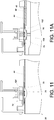
- the first engaging member 76 drives the linking member 34 into displacement in the third direction D3 (see FIG. 11 and FIG. 11A for the linkage therebetween). Consequently, the linking member 34 is displaced from the first position PI to a second position P2 with respect to the post 40a.
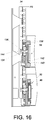
- the linking member 34 will also displace the second locking member 138 of the second interlock device 136 of the second equipment 38 in the third direction D3, thereby blocking a moving path of the second rail 62 of the second slide rail assembly 58 (as described in more detail below with reference to FIG. 15 and FIG. 16 ).
- the second locking member 138 of the second interlock device 136 has a blocking portion 140 for blocking a disengaging portion 142 of the second rail 62 of the second slide rail assembly 58 so that the second interlock device 136 can block the second rail 62 of the second slide rail assembly 58 with the blocking portion 140 in response to displacement of the linking member 34 from the first position PI to the second position P2, with a view to limiting the movement of the second rail 62 of the second slide rail assembly 58 with respect to the first rail 60 in the second direction D2.
- the second rail 50 of the first slide rail assembly 46 can drive the first locking 74 of the first interlock device 72 and thereby displace the linking member 34 from the second position P2 to the first position PI, thanks to the disengaging surface 94b of the disengaging portion 92 of the second rail 50 and the disengaging surface 94a of the blocking portion 90 of the first locking member 74 of the first interlock device 72.
- the second locking member 138 of the second interlock device 136 will not block the second rail 62 of the second slide rail assembly 58 of the second equipment 38.
- the linking member 34 is displaced from the first position PI to the second position P2.
- the second engaging member 144 of the second interlock device 136 (the second engaging member 144 being inserted through the second feature 134 of the linking member 34) is displaced in the third direction D3 along with the linking member 34 and drives the second locking member 138 of the second interlock device 136 in order for the blocking portion 140 of the second locking member 138 of the second interlock device 136 to block the disengaging portion 142 of the second rail 62 of the second slide rail assembly 58.
- FIG. 17 and FIG. 18 show the rack system in the exemplary embodiment that is not forming part of the present invention.
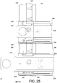
- the exemplary embodiment is different from the first embodiment generally in that the first engaging member 204 of the first interlock device 202 of the first equipment 200 is movably mounted to the supporting rail 208 via an elastic member 206 such as an elastic plate. More specifically, the elastic member 206 is movably connected to the supporting rail 208 and has a hole 212 while the supporting rail 208 has the third opening 210. The first portion 214 of the first engaging member 204 extends through the third opening 210. Referring to FIG. 19 , the first engaging member 204 has a projecting section 216 mounted in the hole 212 of the elastic member 206, and the second portion 218 of the first engaging member 204 is inserted through the first feature 222 of the linking member 220.
- the first equipment 200 is displaced in the first direction D1.
- the first wall 224 of the first equipment 200 is guided by the at least one guiding section 226 (e.g., an inclined surface) of the first engaging member 204 to push and thereby displace the first engaging member 204.
- the elastic member 206 generates and stores an elastic force in response to displacement of the first engaging member 204.
- the first opening 227in the first wall 224 of the first equipment 200 will correspond to the first engaging member 204 such that the first engaging member 204 extends through the first opening 227of the first wall 224 in response to the elastic force of the elastic member 206.
- the linking member 220 is at the first position PI with respect to the first post 228.
- the inclined section 236 of the second guiding portion 234 of the second rail 232 is pressed against the first guiding portion 238 of the first locking member 237 of the first interlock device 202.
- the second rail 232 of the first equipment 200 is further displaced in the second direction D2 and reaches the predetermined position L2 with respect to the first rail 240.
- the second rail 232 of the first equipment 200 is pressed against the first locking member 237 of the first interlock device 202 and thereby displaces the first locking member 237 of the first interlock device 202 in the third direction D3. Consequently, the first engaging member 204 and the elastic member 206 are displaced, driving the linking member 220 from the first position PI to the second position P2 with respect to the first post 228.
- the second engaging member 244 of the second interlock device 242 drives the second locking member 246 of the second interlock device 242 into displacement in the third direction D3, thereby blocking the second rail 250 of the second slide rail assembly 248.
- the second locking member 246 of the second interlock device 242 has a blocking portion 252 for blocking the disengaging portion 254 of the second rail 250 of the second slide rail assembly 248.
Landscapes
- Engineering & Computer Science (AREA)
- Computer Hardware Design (AREA)
- General Engineering & Computer Science (AREA)
- Microelectronics & Electronic Packaging (AREA)
- Drawers Of Furniture (AREA)
- Warehouses Or Storage Devices (AREA)
Claims (14)
- Système de rack (30) caractérisé par le fait qu'il comprend un rack (32), un élément de liaison (34), et un premier équipement (36) incluant un premier ensemble de rails coulissants (46),le premier ensemble de rails coulissants (46) comprend un premier rail (48) et un second rail (50) mobile par rapport au premier rail (48) ;le système de rack caractérisé par le fait qu'il comprend en outre un premier dispositif de verrouillage (72) disposé entre le premier rail (48) du premier ensemble de rails coulissants (46) et l'élément de liaison (34) à travers l'ouverture (70) ;en étant déplacé depuis une position rétractée (L1) par rapport au premier rail (48) du premier ensemble de rails coulissants (46) vers une position prédéterminée (L2) dans une direction d'ouverture, le second rail (50) du premier ensemble de rails coulissants (46) entraîne le premier dispositif de verrouillage (72) et déplace ainsi l'élément de liaison (34) depuis une première position (P1) vers une seconde position (P2) ; etun élément de siège (96) est monté sur un cadre de support (80) du premier rail (48) du premier ensemble de rails coulissants (46), et un premier élément de verrouillage (74) du premier dispositif de verrouillage (72) est monté de manière mobile entre le cadre de support (80) et l'élément de siège (96), et l'élément de siège (96) inclut au moins deux parties de paroi (98a) et (98b) formant un espace (100) entre eux à travers lequel le premier élément de verrouillage (74) est mobile ;caractérisé en ce quele premier équipement (36) inclut un boîtier (42), le boîtier (42) présente une paroi (44, 224), et la paroi (44, 224) présente une ouverture (70, 227), et en ce queun premier élément d'engagement (76) du premier dispositif de verrouillage (72) est monté de manière mobile sur un rail de support (106) via une monture (110), et la monture (110) ou le rail de support (106) présente au moins une fonctionnalité de guidage (112) ; et en ce quela monture (110) est montée de manière mobile sur le rail de support (106) par au moins une fonctionnalité de liaison (114) s'étendant à travers la ou les fonctionnalités de guidage (112), le premier élément d'engagement (76) du premier dispositif de verrouillage (72) peut être disposé sur la monture (110) via au moins une fonctionnalité de support (116).
- Système de rack (30) selon la revendication 1, le premier élément d'engagement (76) inclut une première partie (118) et une deuxième partie (120) reliée à la première partie (118) et la première partie (118) présente au moins une section de guidage (122) étant une surface incurvée, et la seconde partie (120) s'étend à travers la monture (110) et une ouverture (108) du rail de support (106).
- Système de rack (30) selon la revendication 1 ou 2, le système de rack (30) inclut en outre un cadre auxiliaire (126) et au moins un élément de montage (128) relié au cadre auxiliaire (126), le cadre auxiliaire (126) est situé à côté d'un montant (40a) du rack (32), et l'élément de liaison (34) est monté de manière mobile sur le cadre auxiliaire (126), et le ou les éléments de montage (128) ou l'élément de liaison (34) présente au moins un trou de guidage (130) et l'élément de liaison (34) est monté de manière mobile sur le cadre auxiliaire (126) par au moins un élément de liaison (131) s'étendant à travers une partie du trou de guidage (130), et l'élément de liaison (34) présente une pluralité de fonctionnalités telles qu'une première fonctionnalité (132) et une deuxième fonctionnalité (134) et la seconde partie du premier élément d'engagement (76) est insérée à travers la première fonctionnalité (132) de l'élément de liaison (34).
- Système de rack (30) selon l'une quelconque des revendications précédentes, caractérisé par le fait que le premier élément de verrouillage (74) est relié de manière mobile au premier rail (48) du premier ensemble de rails coulissants (46, 230), et le premier élément d'engagement (76) s'étend à travers l'ouverture (70) et est disposé entre le premier élément de verrouillage (74) et l'élément de liaison (34).
- Système de rack (30) selon l'une quelconque des revendications précédentes, caractérisé par le fait que le cadre de support (80) est relié au premier rail (48) du premier ensemble de rails coulissants (46) à une position adjacente à une partie d'extrémité (82) du premier rail (48), le premier élément de verrouillage (74) du premier dispositif de verrouillage (72) étant mobile par rapport au cadre de support (80).
- Système de rack (30) selon l'une quelconque des revendications précédentes, caractérisé par le fait que l'un du second rail (50) du premier ensemble de rails coulissants (46) et du premier élément de verrouillage (74) du premier dispositif de verrouillage (72) comprend une partie de guidage (84, 86) pour guider le second rail (50) du premier ensemble de rails coulissants (46) pour pousser le premier élément de verrouillage (74) du premier dispositif de verrouillage (72).
- Système de rack (30) selon l'une quelconque des revendications précédentes, caractérisé par le fait que la partie de guidage (84, 86) présente une section inclinée (88).
- Système de rack (30) selon l'une quelconque des revendications précédentes, caractérisé par le fait qu'il comprend en outre un second ensemble de rails coulissants (58) et un second dispositif de verrouillage (136), le second ensemble de rails coulissants (58) comprenant un premier rail (60) et un second rail (62) mobile par rapport au premier rail (60), le second dispositif de verrouillage (136) comportant une partie de blocage (140) pour bloquer le second rail (62, 250) du second ensemble de rails coulissants (58) en réponse au déplacement de l'élément de liaison (34) depuis la première position (P1) vers la seconde position (P2).
- Système de rack (30) selon l'une quelconque des revendications précédentes, caractérisé par le fait que le second dispositif de verrouillage (136) comprend un second élément de verrouillage (138) et un second élément d'engagement (144), le second élément de verrouillage (138) est relié de manière mobile au premier rail (60) du second ensemble de rails coulissants (58) et est muni de la partie de blocage (140), et le second élément d'engagement (144) est disposé entre le second élément de verrouillage (138) et l'élément de liaison (34) de sorte que, lorsque l'élément de liaison (34) est déplacé depuis la première position (P1) vers la seconde position (P2), le second élément d'engagement (144) entraîne le second élément de verrouillage (138) de manière à ce que la partie de blocage (140) du second élément de verrouillage (138) bloque le second rail (62) du second ensemble de rails coulissants (58).
- Système de rack (30) selon l'une quelconque des revendications précédentes, caractérisé par le fait que le cadre de support (80) présente une ouverture (102), le premier élément de verrouillage (74) du premier dispositif de verrouillage (72) correspond à l'ouverture (102) du cadre de support (80), et le premier élément d'engagement (76) du premier dispositif de verrouillage (72, 202) est inséré à travers l'ouverture (102) du cadre de support (80).
- Système de rack (30) selon l'une quelconque des revendications précédentes, caractérisé par le fait que le rail de support (106) est monté sur le rack (32) de manière à porter le boîtier (42).
- Système de rack (30) selon l'une quelconque des revendications précédentes, caractérisé par le fait que le premier ensemble de rails coulissants (46) est monté sur la paroi (44) du boîtier (42).
- Système de rack (30) selon l'une quelconque des revendications précédentes, caractérisé par le fait que le second rail (50) du premier ensemble de rails coulissants (46) est configuré pour porter un objet.
- Système de rack (30) selon l'une quelconque des revendications précédentes, caractérisé par le fait qu'il comprend en outre un élément élastique (124) permettant d'appliquer une force élastique sur le premier élément d'engagement (76) du premier dispositif de verrouillage (72).
Applications Claiming Priority (1)
| Application Number | Priority Date | Filing Date | Title |
|---|---|---|---|
| TW104131079A TWI598026B (zh) | 2015-09-18 | 2015-09-18 | 具有連環鎖裝置的滑軌總成 |
Publications (2)
| Publication Number | Publication Date |
|---|---|
| EP3144457A1 EP3144457A1 (fr) | 2017-03-22 |
| EP3144457B1 true EP3144457B1 (fr) | 2019-10-23 |
Family
ID=56800140
Family Applications (1)
| Application Number | Title | Priority Date | Filing Date |
|---|---|---|---|
| EP16182136.8A Active EP3144457B1 (fr) | 2015-09-18 | 2016-08-01 | Système pour rangement avec un ensemble de rail coulissant avec dispositif de verrouillage |
Country Status (4)
| Country | Link |
|---|---|
| US (1) | US9861196B2 (fr) |
| EP (1) | EP3144457B1 (fr) |
| JP (1) | JP6383762B2 (fr) |
| TW (1) | TWI598026B (fr) |
Families Citing this family (15)
| Publication number | Priority date | Publication date | Assignee | Title |
|---|---|---|---|---|
| TWI633829B (zh) * | 2017-08-28 | 2018-08-21 | 川湖科技股份有限公司 | 滑軌總成及滑軌的安裝方法 |
| JP7012499B2 (ja) * | 2017-10-18 | 2022-01-28 | 日本通信電材株式会社 | トレイユニット |
| TWI639377B (zh) * | 2017-12-18 | 2018-10-21 | 川湖科技股份有限公司 | 應用在機架系統的支撐總成 |
| CN109984494B (zh) * | 2018-01-03 | 2021-03-12 | 川湖科技股份有限公司 | 滑轨总成及其滑轨套件 |
| CN110973874A (zh) * | 2019-11-22 | 2020-04-10 | 湖南恺嘉智能科技有限公司 | 一种自锁式滑轨 |
| US12000177B2 (en) * | 2020-02-12 | 2024-06-04 | Raytheon Company | Drawer system and drawer lock |
| CN114135579B (zh) * | 2020-09-03 | 2023-05-12 | 川湖科技股份有限公司 | 滑轨总成及其滑轨套件 |
| TWI751080B (zh) * | 2021-05-04 | 2021-12-21 | 川湖科技股份有限公司 | 滑軌總成及其滑軌套件 |
| US11419226B1 (en) * | 2021-06-18 | 2022-08-16 | ZT Group Int'l, Inc. | Rack-chassis interlock system |
| US12004319B1 (en) * | 2021-12-13 | 2024-06-04 | ZT Group Int'l, Inc. | Rack interlock limiting the withdrawal of chassis |
| US12250784B2 (en) * | 2022-12-20 | 2025-03-11 | Microsoft Technology Licensing, Llc | Equipment locking device |
| TWI834485B (zh) * | 2023-01-19 | 2024-03-01 | 川湖科技股份有限公司 | 滑軌機構 |
| TWI847899B (zh) * | 2023-10-24 | 2024-07-01 | 川湖科技股份有限公司 | 滑軌套件 |
| US20250127301A1 (en) * | 2023-10-24 | 2025-04-24 | Vertiv Corporation | Shelf safety pin for cabinet |
| TWI870191B (zh) * | 2024-01-03 | 2025-01-11 | 川湖科技股份有限公司 | 滑軌機構 |
Family Cites Families (13)
| Publication number | Priority date | Publication date | Assignee | Title |
|---|---|---|---|---|
| US3733113A (en) * | 1971-01-15 | 1973-05-15 | J Glassford | Drawer assembly |
| US4355851A (en) * | 1980-11-28 | 1982-10-26 | Herman Miller, Inc. | Drawer interlock system |
| JPS5958175U (ja) * | 1982-10-13 | 1984-04-16 | 山本 恵一 | 家具 |
| DE29701427U1 (de) * | 1997-01-29 | 1997-03-20 | BSW-Anlagenbau GmbH, 48351 Everswinkel | Krankenhaus-Nachttisch mit gegeneinander verriegelbaren Schubladen |
| US6634726B1 (en) * | 2001-05-30 | 2003-10-21 | Snap-On Technologies, Inc. | Multiple drawer cabinet allowing one drawer opened at a time |
| US6644481B2 (en) * | 2002-02-11 | 2003-11-11 | Hewlett-Packard Development Company, L.P. | Apparatus and method for rackmounting a chassis |
| US7484817B2 (en) | 2002-11-27 | 2009-02-03 | Knape & Vogt Manufacturing Co. | Interlock mechanism for lateral file cabinets |
| GB2429492A (en) * | 2005-08-23 | 2007-02-28 | Kuo-Chan Weng | Linked locking apparatus for drawers |
| US7540573B2 (en) * | 2006-08-30 | 2009-06-02 | Ching-Hsiang Lin | Cabinet with a safety device |
| US8348357B2 (en) * | 2009-07-12 | 2013-01-08 | Matthew Briggs | Drawer assembly locking mechanism |
| TWI411416B (zh) * | 2011-01-21 | 2013-10-11 | King Slide Works Co Ltd | 滑軌連環鎖總成 |
| US8297723B2 (en) | 2011-01-21 | 2012-10-30 | King Slide Works Co., Ltd. | Interlock device for slide assembly |
| CN105578833B (zh) * | 2014-10-14 | 2019-06-28 | 鸿富锦精密电子(天津)有限公司 | 滑轨连锁装置及设有该滑轨连锁装置的电子装置 |
-
2015
- 2015-09-18 TW TW104131079A patent/TWI598026B/zh active
-
2016
- 2016-07-19 US US15/213,645 patent/US9861196B2/en active Active
- 2016-08-01 EP EP16182136.8A patent/EP3144457B1/fr active Active
- 2016-08-05 JP JP2016154297A patent/JP6383762B2/ja active Active
Non-Patent Citations (1)
| Title |
|---|
| None * |
Also Published As
| Publication number | Publication date |
|---|---|
| EP3144457A1 (fr) | 2017-03-22 |
| US9861196B2 (en) | 2018-01-09 |
| TW201713196A (zh) | 2017-04-01 |
| JP6383762B2 (ja) | 2018-08-29 |
| JP2017057707A (ja) | 2017-03-23 |
| TWI598026B (zh) | 2017-09-01 |
| US20170079428A1 (en) | 2017-03-23 |
Similar Documents
| Publication | Publication Date | Title |
|---|---|---|
| EP3144457B1 (fr) | Système pour rangement avec un ensemble de rail coulissant avec dispositif de verrouillage | |
| EP3068199B1 (fr) | Ensemble de rail de glissement | |
| US9723746B2 (en) | Slide rail assembly | |
| EP3082387B1 (fr) | Ensemble de rail de glissement | |
| EP3122164B1 (fr) | Ensemble rail coulissant et son dispositif de support | |
| EP3253189B1 (fr) | Ensemble glissière | |
| EP3398481B1 (fr) | Ensemble de rails de glissement | |
| EP3322269A1 (fr) | Dispositif de support et ensemble de rail coulissant comprenant celui-ci | |
| EP3091824B1 (fr) | Dispositif de support | |
| EP3157312B1 (fr) | Ensemble de rail coulissant et kit de rail de celui-ci | |
| EP3176351B1 (fr) | Rail coulissant et son dispositif de verrouillage | |
| EP3735859B1 (fr) | Ensemble de rails coulissants | |
| EP3231325B1 (fr) | Dispositif de support | |
| EP3352547B1 (fr) | Ensemble de rails de glissement | |
| JP6759404B2 (ja) | スライドレールアセンブリ | |
| EP3153065B1 (fr) | Pièce de montage pour ensemble de rail coulissant | |
| EP3225132B1 (fr) | Mécanisme et procédé de guidage d'éléments de meubles | |
| EP3417740A1 (fr) | Rail télescopique avec mécanisme de blocage | |
| EP3440961A1 (fr) | Ensemble rail de glissière et kit rail de celui-ci | |
| EP2893838B1 (fr) | Ensemble coulissant comprenant une ferrure ajustable | |
| EP3073811A1 (fr) | Ensemble de rail de glissement | |
| EP3167755A1 (fr) | Ensemble de coulisse de tiroir | |
| EP3403530A1 (fr) | Mécanisme d'entraînement, dispositif de protection et procédé de commande applicable au mobilier | |
| CN106559966A (zh) | 具有连环锁装置的滑轨总成 | |
| EP2979582B1 (fr) | Ensemble de rail de glissement |
Legal Events
| Date | Code | Title | Description |
|---|---|---|---|
| PUAI | Public reference made under article 153(3) epc to a published international application that has entered the european phase |
Free format text: ORIGINAL CODE: 0009012 |
|
| STAA | Information on the status of an ep patent application or granted ep patent |
Free format text: STATUS: THE APPLICATION HAS BEEN PUBLISHED |
|
| AK | Designated contracting states |
Kind code of ref document: A1 Designated state(s): AL AT BE BG CH CY CZ DE DK EE ES FI FR GB GR HR HU IE IS IT LI LT LU LV MC MK MT NL NO PL PT RO RS SE SI SK SM TR |
|
| AX | Request for extension of the european patent |
Extension state: BA ME |
|
| STAA | Information on the status of an ep patent application or granted ep patent |
Free format text: STATUS: REQUEST FOR EXAMINATION WAS MADE |
|
| 17P | Request for examination filed |
Effective date: 20170602 |
|
| RBV | Designated contracting states (corrected) |
Designated state(s): AL AT BE BG CH CY CZ DE DK EE ES FI FR GB GR HR HU IE IS IT LI LT LU LV MC MK MT NL NO PL PT RO RS SE SI SK SM TR |
|
| GRAP | Despatch of communication of intention to grant a patent |
Free format text: ORIGINAL CODE: EPIDOSNIGR1 |
|
| STAA | Information on the status of an ep patent application or granted ep patent |
Free format text: STATUS: GRANT OF PATENT IS INTENDED |
|
| INTG | Intention to grant announced |
Effective date: 20190515 |
|
| GRAS | Grant fee paid |
Free format text: ORIGINAL CODE: EPIDOSNIGR3 |
|
| GRAA | (expected) grant |
Free format text: ORIGINAL CODE: 0009210 |
|
| STAA | Information on the status of an ep patent application or granted ep patent |
Free format text: STATUS: THE PATENT HAS BEEN GRANTED |
|
| AK | Designated contracting states |
Kind code of ref document: B1 Designated state(s): AL AT BE BG CH CY CZ DE DK EE ES FI FR GB GR HR HU IE IS IT LI LT LU LV MC MK MT NL NO PL PT RO RS SE SI SK SM TR |
|
| REG | Reference to a national code |
Ref country code: GB Ref legal event code: FG4D |
|
| REG | Reference to a national code |
Ref country code: CH Ref legal event code: EP |
|
| REG | Reference to a national code |
Ref country code: IE Ref legal event code: FG4D |
|
| REG | Reference to a national code |
Ref country code: AT Ref legal event code: REF Ref document number: 1193800 Country of ref document: AT Kind code of ref document: T Effective date: 20191115 |
|
| REG | Reference to a national code |
Ref country code: DE Ref legal event code: R096 Ref document number: 602016022804 Country of ref document: DE |
|
| REG | Reference to a national code |
Ref country code: NL Ref legal event code: MP Effective date: 20191023 |
|
| REG | Reference to a national code |
Ref country code: LT Ref legal event code: MG4D |
|
| PG25 | Lapsed in a contracting state [announced via postgrant information from national office to epo] |
Ref country code: FI Free format text: LAPSE BECAUSE OF FAILURE TO SUBMIT A TRANSLATION OF THE DESCRIPTION OR TO PAY THE FEE WITHIN THE PRESCRIBED TIME-LIMIT Effective date: 20191023 Ref country code: NO Free format text: LAPSE BECAUSE OF FAILURE TO SUBMIT A TRANSLATION OF THE DESCRIPTION OR TO PAY THE FEE WITHIN THE PRESCRIBED TIME-LIMIT Effective date: 20200123 Ref country code: BG Free format text: LAPSE BECAUSE OF FAILURE TO SUBMIT A TRANSLATION OF THE DESCRIPTION OR TO PAY THE FEE WITHIN THE PRESCRIBED TIME-LIMIT Effective date: 20200123 Ref country code: PT Free format text: LAPSE BECAUSE OF FAILURE TO SUBMIT A TRANSLATION OF THE DESCRIPTION OR TO PAY THE FEE WITHIN THE PRESCRIBED TIME-LIMIT Effective date: 20200224 Ref country code: LV Free format text: LAPSE BECAUSE OF FAILURE TO SUBMIT A TRANSLATION OF THE DESCRIPTION OR TO PAY THE FEE WITHIN THE PRESCRIBED TIME-LIMIT Effective date: 20191023 Ref country code: SE Free format text: LAPSE BECAUSE OF FAILURE TO SUBMIT A TRANSLATION OF THE DESCRIPTION OR TO PAY THE FEE WITHIN THE PRESCRIBED TIME-LIMIT Effective date: 20191023 Ref country code: PL Free format text: LAPSE BECAUSE OF FAILURE TO SUBMIT A TRANSLATION OF THE DESCRIPTION OR TO PAY THE FEE WITHIN THE PRESCRIBED TIME-LIMIT Effective date: 20191023 Ref country code: NL Free format text: LAPSE BECAUSE OF FAILURE TO SUBMIT A TRANSLATION OF THE DESCRIPTION OR TO PAY THE FEE WITHIN THE PRESCRIBED TIME-LIMIT Effective date: 20191023 Ref country code: GR Free format text: LAPSE BECAUSE OF FAILURE TO SUBMIT A TRANSLATION OF THE DESCRIPTION OR TO PAY THE FEE WITHIN THE PRESCRIBED TIME-LIMIT Effective date: 20200124 Ref country code: LT Free format text: LAPSE BECAUSE OF FAILURE TO SUBMIT A TRANSLATION OF THE DESCRIPTION OR TO PAY THE FEE WITHIN THE PRESCRIBED TIME-LIMIT Effective date: 20191023 |
|
| PG25 | Lapsed in a contracting state [announced via postgrant information from national office to epo] |
Ref country code: HR Free format text: LAPSE BECAUSE OF FAILURE TO SUBMIT A TRANSLATION OF THE DESCRIPTION OR TO PAY THE FEE WITHIN THE PRESCRIBED TIME-LIMIT Effective date: 20191023 Ref country code: RS Free format text: LAPSE BECAUSE OF FAILURE TO SUBMIT A TRANSLATION OF THE DESCRIPTION OR TO PAY THE FEE WITHIN THE PRESCRIBED TIME-LIMIT Effective date: 20191023 Ref country code: IS Free format text: LAPSE BECAUSE OF FAILURE TO SUBMIT A TRANSLATION OF THE DESCRIPTION OR TO PAY THE FEE WITHIN THE PRESCRIBED TIME-LIMIT Effective date: 20200224 |
|
| PG25 | Lapsed in a contracting state [announced via postgrant information from national office to epo] |
Ref country code: AL Free format text: LAPSE BECAUSE OF FAILURE TO SUBMIT A TRANSLATION OF THE DESCRIPTION OR TO PAY THE FEE WITHIN THE PRESCRIBED TIME-LIMIT Effective date: 20191023 |
|
| REG | Reference to a national code |
Ref country code: DE Ref legal event code: R097 Ref document number: 602016022804 Country of ref document: DE |
|
| PG2D | Information on lapse in contracting state deleted |
Ref country code: IS |
|
| PG25 | Lapsed in a contracting state [announced via postgrant information from national office to epo] |
Ref country code: ES Free format text: LAPSE BECAUSE OF FAILURE TO SUBMIT A TRANSLATION OF THE DESCRIPTION OR TO PAY THE FEE WITHIN THE PRESCRIBED TIME-LIMIT Effective date: 20191023 Ref country code: DK Free format text: LAPSE BECAUSE OF FAILURE TO SUBMIT A TRANSLATION OF THE DESCRIPTION OR TO PAY THE FEE WITHIN THE PRESCRIBED TIME-LIMIT Effective date: 20191023 Ref country code: EE Free format text: LAPSE BECAUSE OF FAILURE TO SUBMIT A TRANSLATION OF THE DESCRIPTION OR TO PAY THE FEE WITHIN THE PRESCRIBED TIME-LIMIT Effective date: 20191023 Ref country code: CZ Free format text: LAPSE BECAUSE OF FAILURE TO SUBMIT A TRANSLATION OF THE DESCRIPTION OR TO PAY THE FEE WITHIN THE PRESCRIBED TIME-LIMIT Effective date: 20191023 Ref country code: RO Free format text: LAPSE BECAUSE OF FAILURE TO SUBMIT A TRANSLATION OF THE DESCRIPTION OR TO PAY THE FEE WITHIN THE PRESCRIBED TIME-LIMIT Effective date: 20191023 Ref country code: IS Free format text: LAPSE BECAUSE OF FAILURE TO SUBMIT A TRANSLATION OF THE DESCRIPTION OR TO PAY THE FEE WITHIN THE PRESCRIBED TIME-LIMIT Effective date: 20200223 |
|
| REG | Reference to a national code |
Ref country code: AT Ref legal event code: MK05 Ref document number: 1193800 Country of ref document: AT Kind code of ref document: T Effective date: 20191023 |
|
| PLBE | No opposition filed within time limit |
Free format text: ORIGINAL CODE: 0009261 |
|
| STAA | Information on the status of an ep patent application or granted ep patent |
Free format text: STATUS: NO OPPOSITION FILED WITHIN TIME LIMIT |
|
| PG25 | Lapsed in a contracting state [announced via postgrant information from national office to epo] |
Ref country code: SK Free format text: LAPSE BECAUSE OF FAILURE TO SUBMIT A TRANSLATION OF THE DESCRIPTION OR TO PAY THE FEE WITHIN THE PRESCRIBED TIME-LIMIT Effective date: 20191023 Ref country code: IT Free format text: LAPSE BECAUSE OF FAILURE TO SUBMIT A TRANSLATION OF THE DESCRIPTION OR TO PAY THE FEE WITHIN THE PRESCRIBED TIME-LIMIT Effective date: 20191023 Ref country code: SM Free format text: LAPSE BECAUSE OF FAILURE TO SUBMIT A TRANSLATION OF THE DESCRIPTION OR TO PAY THE FEE WITHIN THE PRESCRIBED TIME-LIMIT Effective date: 20191023 |
|
| 26N | No opposition filed |
Effective date: 20200724 |
|
| PG25 | Lapsed in a contracting state [announced via postgrant information from national office to epo] |
Ref country code: AT Free format text: LAPSE BECAUSE OF FAILURE TO SUBMIT A TRANSLATION OF THE DESCRIPTION OR TO PAY THE FEE WITHIN THE PRESCRIBED TIME-LIMIT Effective date: 20191023 Ref country code: SI Free format text: LAPSE BECAUSE OF FAILURE TO SUBMIT A TRANSLATION OF THE DESCRIPTION OR TO PAY THE FEE WITHIN THE PRESCRIBED TIME-LIMIT Effective date: 20191023 |
|
| PG25 | Lapsed in a contracting state [announced via postgrant information from national office to epo] |
Ref country code: MC Free format text: LAPSE BECAUSE OF FAILURE TO SUBMIT A TRANSLATION OF THE DESCRIPTION OR TO PAY THE FEE WITHIN THE PRESCRIBED TIME-LIMIT Effective date: 20191023 |
|
| REG | Reference to a national code |
Ref country code: CH Ref legal event code: PL |
|
| PG25 | Lapsed in a contracting state [announced via postgrant information from national office to epo] |
Ref country code: LU Free format text: LAPSE BECAUSE OF NON-PAYMENT OF DUE FEES Effective date: 20200801 Ref country code: LI Free format text: LAPSE BECAUSE OF NON-PAYMENT OF DUE FEES Effective date: 20200831 Ref country code: CH Free format text: LAPSE BECAUSE OF NON-PAYMENT OF DUE FEES Effective date: 20200831 |
|
| REG | Reference to a national code |
Ref country code: BE Ref legal event code: MM Effective date: 20200831 |
|
| PG25 | Lapsed in a contracting state [announced via postgrant information from national office to epo] |
Ref country code: FR Free format text: LAPSE BECAUSE OF NON-PAYMENT OF DUE FEES Effective date: 20200831 |
|
| PG25 | Lapsed in a contracting state [announced via postgrant information from national office to epo] |
Ref country code: BE Free format text: LAPSE BECAUSE OF NON-PAYMENT OF DUE FEES Effective date: 20200831 |
|
| PG25 | Lapsed in a contracting state [announced via postgrant information from national office to epo] |
Ref country code: TR Free format text: LAPSE BECAUSE OF FAILURE TO SUBMIT A TRANSLATION OF THE DESCRIPTION OR TO PAY THE FEE WITHIN THE PRESCRIBED TIME-LIMIT Effective date: 20191023 Ref country code: MT Free format text: LAPSE BECAUSE OF FAILURE TO SUBMIT A TRANSLATION OF THE DESCRIPTION OR TO PAY THE FEE WITHIN THE PRESCRIBED TIME-LIMIT Effective date: 20191023 Ref country code: CY Free format text: LAPSE BECAUSE OF FAILURE TO SUBMIT A TRANSLATION OF THE DESCRIPTION OR TO PAY THE FEE WITHIN THE PRESCRIBED TIME-LIMIT Effective date: 20191023 |
|
| PG25 | Lapsed in a contracting state [announced via postgrant information from national office to epo] |
Ref country code: MK Free format text: LAPSE BECAUSE OF FAILURE TO SUBMIT A TRANSLATION OF THE DESCRIPTION OR TO PAY THE FEE WITHIN THE PRESCRIBED TIME-LIMIT Effective date: 20191023 |
|
| PGFP | Annual fee paid to national office [announced via postgrant information from national office to epo] |
Ref country code: GB Payment date: 20250606 Year of fee payment: 10 |
|
| PGFP | Annual fee paid to national office [announced via postgrant information from national office to epo] |
Ref country code: IE Payment date: 20250616 Year of fee payment: 10 |
|
| PGFP | Annual fee paid to national office [announced via postgrant information from national office to epo] |
Ref country code: DE Payment date: 20250611 Year of fee payment: 10 |