EP3176351B1 - Rail coulissant et son dispositif de verrouillage - Google Patents
Rail coulissant et son dispositif de verrouillage Download PDFInfo
- Publication number
- EP3176351B1 EP3176351B1 EP16188890.4A EP16188890A EP3176351B1 EP 3176351 B1 EP3176351 B1 EP 3176351B1 EP 16188890 A EP16188890 A EP 16188890A EP 3176351 B1 EP3176351 B1 EP 3176351B1
- Authority
- EP
- European Patent Office
- Prior art keywords
- rail
- engaging
- respect
- engaging member
- releasing
- Prior art date
- Legal status (The legal status is an assumption and is not a legal conclusion. Google has not performed a legal analysis and makes no representation as to the accuracy of the status listed.)
- Active
Links
Images


Classifications
-
- A—HUMAN NECESSITIES
- A47—FURNITURE; DOMESTIC ARTICLES OR APPLIANCES; COFFEE MILLS; SPICE MILLS; SUCTION CLEANERS IN GENERAL
- A47B—TABLES; DESKS; OFFICE FURNITURE; CABINETS; DRAWERS; GENERAL DETAILS OF FURNITURE
- A47B96/00—Details of cabinets, racks or shelf units not covered by a single one of groups A47B43/00 - A47B95/00; General details of furniture
- A47B96/06—Brackets or similar supporting means for cabinets, racks or shelves
- A47B96/07—Brackets or similar supporting means for cabinets, racks or shelves adjustable in themselves
-
- E—FIXED CONSTRUCTIONS
- E05—LOCKS; KEYS; WINDOW OR DOOR FITTINGS; SAFES
- E05B—LOCKS; ACCESSORIES THEREFOR; HANDCUFFS
- E05B65/00—Locks or fastenings for special use
- E05B65/46—Locks or fastenings for special use for drawers
- E05B65/462—Locks or fastenings for special use for drawers for two or more drawers
- E05B65/463—Drawer interlock or anti-tilt mechanisms, i.e. when one drawer is open, at least one of the remaining drawers is locked
-
- A—HUMAN NECESSITIES
- A47—FURNITURE; DOMESTIC ARTICLES OR APPLIANCES; COFFEE MILLS; SPICE MILLS; SUCTION CLEANERS IN GENERAL
- A47B—TABLES; DESKS; OFFICE FURNITURE; CABINETS; DRAWERS; GENERAL DETAILS OF FURNITURE
- A47B96/00—Details of cabinets, racks or shelf units not covered by a single one of groups A47B43/00 - A47B95/00; General details of furniture
- A47B96/06—Brackets or similar supporting means for cabinets, racks or shelves
- A47B96/067—Horizontal rails as suspension means in a cantilever arrangement
-
- E—FIXED CONSTRUCTIONS
- E05—LOCKS; KEYS; WINDOW OR DOOR FITTINGS; SAFES
- E05B—LOCKS; ACCESSORIES THEREFOR; HANDCUFFS
- E05B65/00—Locks or fastenings for special use
- E05B65/46—Locks or fastenings for special use for drawers
-
- E—FIXED CONSTRUCTIONS
- E05—LOCKS; KEYS; WINDOW OR DOOR FITTINGS; SAFES
- E05C—BOLTS OR FASTENING DEVICES FOR WINGS, SPECIALLY FOR DOORS OR WINDOWS
- E05C3/00—Fastening devices with bolts moving pivotally or rotatively
- E05C3/02—Fastening devices with bolts moving pivotally or rotatively without latching action
- E05C3/06—Fastening devices with bolts moving pivotally or rotatively without latching action with operating handle or equivalent member moving otherwise than rigidly with the bolt
-
- E—FIXED CONSTRUCTIONS
- E05—LOCKS; KEYS; WINDOW OR DOOR FITTINGS; SAFES
- E05C—BOLTS OR FASTENING DEVICES FOR WINGS, SPECIALLY FOR DOORS OR WINDOWS
- E05C3/00—Fastening devices with bolts moving pivotally or rotatively
- E05C3/12—Fastening devices with bolts moving pivotally or rotatively with latching action
-
- A—HUMAN NECESSITIES
- A47—FURNITURE; DOMESTIC ARTICLES OR APPLIANCES; COFFEE MILLS; SPICE MILLS; SUCTION CLEANERS IN GENERAL
- A47B—TABLES; DESKS; OFFICE FURNITURE; CABINETS; DRAWERS; GENERAL DETAILS OF FURNITURE
- A47B2210/00—General construction of drawers, guides and guide devices
- A47B2210/0002—Guide construction for drawers
- A47B2210/0018—Buffers, stop blocks or latches for single drawer slides
Definitions
- the present invention relates to a slide rail assembly and more particularly to a slide rail assembly whose unlocking operation and interlocking operation are carried out separately.
- US Patent No. 8,282,176 B1 granted to Chen et al. discloses a locking mechanism for locking a slide rail assembly in the retracted state.
- the locking mechanism includes a stop, a locking member, a release member, and a resilient member.
- the stop is located at a first rail.
- the locking member is pivotally connected to a second rail.
- the release member has a window for receiving the locking member, wherein an inside of the window has an inclined surface corresponding to the locking member.
- the resilient member is in contact between the locking member and an inner edge of the window of the release member so as to keep the locking member corresponding to the stop.
- the second rail is retracted with respect to the first rail, the locking member and the stop are engaged with each other, with the resilient member in resilient contact with the locking member.
- the operation portion of the release member is pulled outward, the locking member is guided by the inclined surface of the window of the release member and thus pivoted out of engagement with the stop.
- the ' 176 patent discloses an operation method
- US Patent No. 8,297,723 B2 granted to Chen et al. , discloses an interlock device configured for a slide rail assembly and including an outer rail, an intermediate rail, an inner rail, a base, a driving member, a stop, and a locking member.
- the base is fixedly connected to one end of the outer rail and includes a top room and a bottom room corresponding to the top room.
- the driving member is movably connected to the base and includes a driving portion, an engaging portion corresponding to the driving portion, and a co-moving portion between the driving portion and the engaging portion.
- the driving portion is located in the top room of the base and is partially exposed from the top room.
- the engaging portion is located in the bottom room of the base.
- the stop is connected to either the inner rail or the intermediate rail.
- the locking member is connected to the co-moving portion.
- the driving portion of the driving member is pushed by the intermediate rail and thus retracted into the top room of the base.
- the co-moving portion is moved from a first position to a second position to shift the locking member, and the engaging portion extends out of the bottom room of the base.
- the '723 patent discloses an interlock device whereby, when a rail is pulled out, all the other rails to be controlled by the interlock device are kept from being pulled out at the same time.
- US 2012/187816 A1 discloses an interlock device having an outer rail, an inner rail, a base, a driving member, a stop and a locking member.
- the base is connected to one end of the outer rail and includes a top room and a bottom room.
- the driving member is movable and includes a driving portion, an engaging portion and a co-moving portion.
- the driving portion is located in the top room and partially exposed from the top room.
- the engaging portion is located in the bottom room.
- the stop is connected to the inner rail.
- the locking member is connected to the co-moving portion.
- WO 2008/076873 A1 and US 2011/121701A1 each disclose a slide rail assembly according to the preamble of claim 1.
- the slide rail assembly comprises a first rail, a second rail displaceable between a retracted position and an extended position with respect to the first rail, a stop and a locking device, the stop being connected to the first rail.
- the locking device comprises a first engaging member and a first releasing member. The first engaging member is pivotally connected to the second rail, and when the second rail is at the retracted position with respect to the first rail, the first engaging member is at an engaged position with respect to the stop.
- the first releasing member is configured to operatively drive the first engaging member away from the engaged position, thereby allowing the second rail to be displaced from the retracted position toward the extended position with respect to the first rail.
- the slide rail assembly further comprises an elastic member for applying an elastic force to the first engaging member.
- the present invention relates to a slide rail assembly configured to be unlocked and perform an interlocking operation separately.
- a slide rail assembly includes a first rail, a second rail, a stop, a first engaging member, and a first releasing member.
- the second rail can be displaced between a retracted position and an extended position with respect to the first rail.
- the stop is located at the first rail.
- the first engaging member is movably connected to the second rail, and when the second rail is at the retracted position with respect to the first rail, the first engaging member is at an engaged positon with respect to the stop.
- the first releasing member is configured to operatively drive the first engaging member away from the engaged position, thereby allowing the second rail to be displaced from the retracted position toward the extended position with respect to the first rail.
- the locking device further comprises an elastic member for applying an elastic force to the first engaging member.
- the slide rail assembly further comprises a bracket and the locking device further includes a second releasing member connected to the second rail and a second engaging member.
- the slide rail assembly is configured to be mounted to a rack, and the bracket is connected to the first rail and has an opening and is connectable to the rack and the second engaging member is movably mounted on the bracket, has an engaging projection jutting out of the opening of the bracket, and is configured to be driven by the second releasing member so that the engaging projection of the second engaging member is displaced and drives a driven member which is movably mounted on the rack into displacement.
- the stop is connected to the first rail via the bracket.
- the elastic member is pressed against the stop of the bracket such that the first engaging member returns to the engaged position due to the elastic force of the elastic member and thus displaces the first releasing member with respect to the second releasing member.
- the elastic member applies the elastic force to the first engaging member so that the first engaging member stays at the engaged position in response to the elastic force of the elastic member.
- the first releasing member is vertically movably mounted above the second releasing member.
- the slide rail assembly further includes a third rail movably connected between the first rail and the second rail.
- the second releasing member has a first inclined guide portion
- the second engaging member has a second inclined guide portion matching the first inclined guide portion so that, when displaced with respect to the second engaging member, the second releasing member can displace the second engaging member with ease.
- a locking device of a slide rail assembly wherein the slide rail assembly includes a first rail, a second rail displaceable between a retracted positon and an extended position with respect to the first rail, a bracket connected to the first rail, and a stop located at the bracket.
- the locking device includes a first engaging member pivotally connectable to the second rail, an elastic member for applying an elastic force to the first engaging member in order for the first engaging member to stay at an engaged position in response to the elastic force of the elastic member, a first releasing member, and a second releasing member connected to the second rail, wherein the first releasing member is movable with respect to the second releasing member.
- the first releasing member is configured to operatively drive the first engaging member away from the engaged position, thereby allowing the second rail to be displaced from the retracted position toward the extended position with respect to the first rail.
- the locking device further includes a third rail movably connected between the first rail and the second rail.
- the slide rail assembly 10 in an embodiment of the present invention is mounted on a rack 12.
- the slide rail assembly 10 includes a first rail 14, a second rail 16, a third rail 18, and a locking device 20. More specifically, the first rail 14 is the outer rail, the second rail 16 is the inner rail, and the third rail 18 is the intermediate rail.
- the third rail 18 is movably connected between the first rail 14 and the second rail 16 to increase the distance by which the second rail 16 can be displaced with respect to the first rail 14.
- the locking device 20 is configured to lock the second rail 16 in position with respect to the first rail 14 when the second rail 16 is retracted with respect to the first rail 14.
- This embodiment further includes a bracket 22 connected to the first rail 14, and the slide rail assembly 10 is mounted to the rack 12 via the bracket 22.
- the bracket 22 is connected to the first rail 14 and thus increases the length of the first rail 14. From the perspective of practical use and structural equivalence, therefore, the bracket 22 can be viewed as a portion of the first rail 14.
- the bracket 22 includes a stop 24 and an opening 26.
- the locking device 20 includes a first engaging member 28 and an elastic member 30.
- the first engaging member 28 is movably, e.g., pivotally, connected to the second rail 16.
- the elastic member 30 applies an elastic force to the first engaging member 28, and in response to the elastic force of the elastic member 30, the first engaging member 28 stays at an engaged position L with respect to the stop 24.
- the elastic member 30, which can be a torsion spring for example, has an elastic portion 32 corresponding in position to the stop 24.
- the locking device 20 includes a first releasing member 34 and a second releasing member 36.
- the first releasing member 34 is movably mounted with respect to the second releasing member 36.
- the first releasing member 34 is vertically movably mounted above the second releasing member 36 and corresponds to a portion of the first engaging member 28.
- the second releasing member 36 is connected to the second rail 16.
- the slide rail assembly 10 in this state is locked, meaning the second rail 16 is at a retracted position P1 with respect to the first rail 14 and cannot be pulled away from the retracted position P1.
- the first releasing member 34 drives the first engaging member 28 away from the engaged position L such that the slide rail assembly 10 is released from the locked state, allowing the second rail 16 to be pulled in a direction D from the retracted position P1 to an extended position P2, or even farther, with respect to the first rail 14.
- the elastic portion 32 of the elastic member 30 is pressed against the stop 24 of the bracket 22. Consequently, the first engaging member 28 is pivoted by the elastic force of the elastic member 30 and thus displaces the first releasing member 34 with respect to the second releasing member 36, bringing the first releasing member 34 back to the state in FIG. 2 with respect to the second releasing member 36, i.e., the state in which the first releasing member 34 is located above the second releasing member 36 and propped up by the first engaging member 28.
- this embodiment further includes a second engaging member 38 movably mounted on the bracket 22.
- the second engaging member 38 has an engaging projection 40 jutting out of the opening 26 of the bracket 22, as shown in FIG. 5 .
- the second releasing member 36 has a first inclined guide portion 42
- the second engaging member 38 has a second inclined guide portion 44 matching the first inclined guide portion 42 so that, when the second releasing member 36 is displaced with respect to the second engaging member 38, the second engaging member 38 can be displaced by the second releasing member 36 with ease.
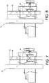
- this embodiment includes a driven member 46 movably mounted on the rack 12. While the second rail 16 is being pulled out with respect to the first rail 14, the second engaging member 38 is displaced by the second releasing member 36; as a result, the engaging projection 40 of the second engaging member 3 8 drives the driven member 46 into displacement. More specifically, the driven member 46 is displaced from a first position X1 to a second position X2, as shown in FIG. 7 and FIG. 8 .
- the driven member 46 movably mounted on the rack 12 is configured to lock all the slide rail assemblies on the rack 12 other than the one pulled out. Therefore, when one of a plurality of slide rail assemblies mounted on the rack 12 is pulled out, the remaining slide rail assemblies on the rack 12 are locked and prevented from being pulled out.
- the interlocking technique employed is well known in the art and has been described above in the Background of the Invention section, no further description is provided herein.
- the present invention is so designed that unlocking precedes the interlocking operation, and this design effectively avoids problems associated with simultaneous unlocking and interlocking.
- the present invention thus enables safer and more reliable operation than the prior art.
Landscapes
- Engineering & Computer Science (AREA)
- Mechanical Engineering (AREA)
- Drawers Of Furniture (AREA)
Claims (6)
- Ensemble coulissant de rails (10), caractérisé par le fait qu'il comprend :un premier rail (14) ;un deuxième rail (16) déplaçable entre une position rétractée (P1) et une position déployée (P2) par rapport au premier rail (14) ;une butée (24) et un dispositif de verrouillage (20), la butée (24) étant raccordée au premier rail (14) ;le dispositif de verrouillage (20) comprend un premier élément de mise en prise (28) et un premier élément de libération (34) ;le premier élément de mise en prise (28) est raccordé de manière pivotante au deuxième rail (16), et lorsque le deuxième rail (16) est sur la position rétractée (P1) par rapport au premier rail (14), le premier élément de mise en prise (28) est dans une position de mise en prise (L) par rapport à la butée (24) ; etle premier élément de libération (34) est configuré pour entraîner fonctionnellement le premier élément de mise en prise (28) à l'écart de la position de mise en prise (L), permettant ainsi au deuxième rail (16) d'être déplacé depuis la position rétractée (P1) vers la position déployée (P2) par rapport au premier rail (14), etle dispositif de verrouillage (20) comprend en outre un élément résilient (30) pour appliquer une force résiliente au premier élément de mise en prise (28) caractérisé en ce quel'ensemble coulissant de rails (10) comprend en outre un support (22), et le dispositif de verrouillage (20) comprend en outre un second élément de libération (36) raccordé au deuxième rail (16) et un second élément de mise en prise (38), et en ce quel'ensemble coulissant de rails (10) est configuré pour être monté sur un rack (12), et le support (22) est raccordé au premier rail (14) et comporte une ouverture (26) et est connectable au rack (12), et le second élément de mise en prise (38) est monté de manière mobile sur le support (22), comporte une saillie de prise (40) en saillie par rapport à l'ouverture (26) du support (22), et est configuré pour être entraîné par le second élément de libération (36) de sorte que la saillie de prise (40) du second élément de mise en prise (38) est déplacée et déplace un élément entraîné (46) qui est monté de manière mobile sur le rack (12), et en ce quela butée (24) est raccordée au premier rail (14) via le support (22) ; et en ce queune fois que le deuxième rail (16) est déplacé depuis la position déployée (P2) vers la position rétractée (P1) par rapport au premier rail (14) et atteint une position prédéterminée, l'élément résilient (30) est pressé contre la butée (24) du support (22) de sorte que le premier élément de mise en prise (28) retourne vers la position de mise en prise (L) du fait de la force résiliente de l'élément résilient (30) et déplace alors le premier élément de libération (34) par rapport au second élément de libération (36).
- Ensemble coulissant de rails (10) selon la revendication 1, l'élément résilient (30) applique la force résiliente au premier élément de mise en prise (28) pour que le premier élément de mise en prise (28) reste sur la position de mise en prise (L) en réponse à la force résiliente de l'élément résilient (30).
- Ensemble coulissant de rails (10) selon la revendication 1, caractérisé par le fait que le premier élément de libération (34) est monté verticalement de manière mobile au dessus du second élément de libération (36).
- Ensemble coulissant de rails (10) selon la revendication 1, caractérisé par le fait que le premier élément de libération (34) est monté de manière mobile par rapport au second élément de libération (36).
- Ensemble coulissant de rails (10) selon l'une quelconque des revendications 1 et 4, caractérisé par le fait qu'il comprend en outre un troisième rail (18) raccordé de manière mobile entre le premier rail (14) et le deuxième rail (16).
- Ensemble coulissant de rails (10) selon la revendication 1, caractérisé par le fait que le second élément de libération (36) comporte une première partie de guidage inclinée (42), et le second élément de mise en prise (38) comporte une seconde partie de guidage inclinée (44) correspondant à la première partie de guidage inclinée (42) pour faciliter le déplacement du second élément de mise en prise (38) par le second élément de libération (36) lorsque le second élément de libération (36) est déplacé par rapport au second élément de mise en prise (38).
Applications Claiming Priority (1)
| Application Number | Priority Date | Filing Date | Title |
|---|---|---|---|
| TW104140668A TWI587814B (zh) | 2015-12-03 | 2015-12-03 | 滑軌總成及其鎖定裝置 |
Publications (2)
| Publication Number | Publication Date |
|---|---|
| EP3176351A1 EP3176351A1 (fr) | 2017-06-07 |
| EP3176351B1 true EP3176351B1 (fr) | 2018-06-27 |
Family
ID=56985458
Family Applications (1)
| Application Number | Title | Priority Date | Filing Date |
|---|---|---|---|
| EP16188890.4A Active EP3176351B1 (fr) | 2015-12-03 | 2016-09-15 | Rail coulissant et son dispositif de verrouillage |
Country Status (4)
| Country | Link |
|---|---|
| US (1) | US10098459B2 (fr) |
| EP (1) | EP3176351B1 (fr) |
| JP (1) | JP6393717B2 (fr) |
| TW (1) | TWI587814B (fr) |
Families Citing this family (14)
| Publication number | Priority date | Publication date | Assignee | Title |
|---|---|---|---|---|
| US10492321B2 (en) * | 2017-02-09 | 2019-11-26 | Western Digital Technologies, Inc. | Self-actuating latch for a rack mounted drive chassis |
| US10206504B2 (en) * | 2017-04-06 | 2019-02-19 | American Bolt & Screw Mfg. Inc. | Locking recreational vehicle drawer |
| US10356931B1 (en) * | 2017-05-26 | 2019-07-16 | King Slide Works Co., Ltd. | Rack mounting system |
| CN116439520B (zh) * | 2017-09-08 | 2026-04-24 | 川湖科技股份有限公司 | 滑轨总成及其滑轨机构 |
| US10383248B1 (en) * | 2018-06-15 | 2019-08-13 | Super Micro Computer Inc. | Locking mechanism and server having the same |
| WO2021146348A1 (fr) * | 2020-01-13 | 2021-07-22 | Accuride International Inc. | Verrouillage de glissière |
| CN113923922B (zh) * | 2020-07-07 | 2023-06-13 | 金竣企业股份有限公司 | 服务器滑轨与服务器机架的安装结构 |
| AT524352B1 (de) * | 2020-09-28 | 2022-07-15 | Fulterer Ag & Co Kg | Ausziehsperrvorrichtung für Schubladen |
| TWI733625B (zh) * | 2020-11-24 | 2021-07-11 | 川湖科技股份有限公司 | 滑軌總成 |
| CN114554772B (zh) * | 2020-11-27 | 2024-12-27 | 川湖科技股份有限公司 | 滑轨总成 |
| TWI852817B (zh) * | 2022-09-02 | 2024-08-11 | 恒昌行精密工業有限公司 | 機箱快拆裝置 |
| TWI861632B (zh) * | 2022-12-13 | 2024-11-11 | 川湖科技股份有限公司 | 滑軌總成 |
| TWI847902B (zh) * | 2023-10-30 | 2024-07-01 | 川湖科技股份有限公司 | 滑軌總成 |
| TWI847910B (zh) * | 2023-11-09 | 2024-07-01 | 川湖科技股份有限公司 | 滑軌總成 |
Family Cites Families (24)
| Publication number | Priority date | Publication date | Assignee | Title |
|---|---|---|---|---|
| US5634701A (en) * | 1994-08-31 | 1997-06-03 | Fireking International, Inc. | Multi-drawer cabinet having a drawer lock-out mechanism |
| US6702412B2 (en) * | 2001-09-19 | 2004-03-09 | Hewlett-Packard Development Company, L.P. | Expandable slide and rail assembly for a rack and method of installing same |
| US6749276B2 (en) * | 2001-10-01 | 2004-06-15 | Jonathan Manufacturing Corp. | Sequencing mechanism for slide assembly |
| US6773080B2 (en) * | 2002-12-06 | 2004-08-10 | King Slide Works, Co., Ltd. | Bracket device for a track assembly |
| US6997528B2 (en) * | 2003-10-29 | 2006-02-14 | Jun-Long Yang | Rail assembly for furniture |
| US20060066187A1 (en) * | 2004-09-27 | 2006-03-30 | Ching-Chang Chang | Lock mechanism for cabinet |
| JP3109546U (ja) * | 2004-12-24 | 2005-05-19 | 丸信實業股▲ふん▼有限公司 | スライド棚板位置決め装置 |
| US7144092B1 (en) * | 2006-01-11 | 2006-12-05 | Ting-Wei Chang | Arresting apparatus of multilayer drawers |
| TWI297596B (en) * | 2006-09-21 | 2008-06-11 | Sun Chain Metal Industry Co Ltd | Interlocking device for a drawer guideway |
| MX2009006400A (es) | 2006-12-14 | 2009-11-11 | Waterloo Ind Inc | Cerrojo para cajon. |
| US7703734B2 (en) * | 2007-12-27 | 2010-04-27 | King Slide Works Co., Ltd. | Slide mounting bracket structure |
| TWI346861B (en) * | 2008-05-28 | 2011-08-11 | King Slide Works Co Ltd | Slide assembly for a rack |
| CN101606790B (zh) * | 2008-06-19 | 2012-05-30 | 鸿富锦精密工业(深圳)有限公司 | 滑轨固定装置 |
| TWI402046B (zh) * | 2009-04-10 | 2013-07-21 | King Slide Works Co Ltd | 用於滑軌組件之彈性機構 |
| TWM379377U (en) * | 2009-11-25 | 2010-05-01 | ting-yu Zhang | Latching structure of cabinet drawer |
| US8220879B2 (en) * | 2010-01-19 | 2012-07-17 | Martas Precision Slide Co., Ltd. | Interlocking device for slide rail |
| IT1402559B1 (it) * | 2010-11-08 | 2013-09-13 | Unifor Spa | Meccanismo di chiusura di sportelli scorrevoli |
| US8297723B2 (en) * | 2011-01-21 | 2012-10-30 | King Slide Works Co., Ltd. | Interlock device for slide assembly |
| US8282176B1 (en) * | 2011-06-10 | 2012-10-09 | King Slide Works Co., Ltd. | Slide assembly having locking mechanism |
| US8231188B1 (en) * | 2011-07-15 | 2012-07-31 | King Slide Works Co., Ltd. | Support mechanism for slide assembly |
| TWI428102B (zh) * | 2011-07-21 | 2014-03-01 | Sun Chain Metal Industry Co Ltd | 抽屜滑軌之連動互鎖結構 |
| TWI448263B (zh) * | 2012-05-30 | 2014-08-11 | King Slide Works Co Ltd | 滑軌總成 |
| TWI590784B (zh) * | 2015-03-12 | 2017-07-11 | King Slide Works Co | 滑軌總成 |
| TWI598019B (zh) * | 2015-07-15 | 2017-09-01 | King Slide Works Co Ltd | 滑軌總成及其托架裝置 |
-
2015
- 2015-12-03 TW TW104140668A patent/TWI587814B/zh active
-
2016
- 2016-09-02 US US15/255,510 patent/US10098459B2/en active Active
- 2016-09-13 JP JP2016178320A patent/JP6393717B2/ja active Active
- 2016-09-15 EP EP16188890.4A patent/EP3176351B1/fr active Active
Non-Patent Citations (1)
| Title |
|---|
| None * |
Also Published As
| Publication number | Publication date |
|---|---|
| TW201720342A (zh) | 2017-06-16 |
| JP2017099851A (ja) | 2017-06-08 |
| US10098459B2 (en) | 2018-10-16 |
| US20170156498A1 (en) | 2017-06-08 |
| EP3176351A1 (fr) | 2017-06-07 |
| JP6393717B2 (ja) | 2018-09-19 |
| TWI587814B (zh) | 2017-06-21 |
Similar Documents
| Publication | Publication Date | Title |
|---|---|---|
| EP3176351B1 (fr) | Rail coulissant et son dispositif de verrouillage | |
| EP3144457B1 (fr) | Système pour rangement avec un ensemble de rail coulissant avec dispositif de verrouillage | |
| EP3387950B1 (fr) | Ensemble de rails de glissement | |
| EP3068199B1 (fr) | Ensemble de rail de glissement | |
| EP3679833B1 (fr) | Ensemble de rail coulissant | |
| CN107075885B (zh) | 进退移动装置 | |
| EP2915939B1 (fr) | Serrure | |
| EP3112217B1 (fr) | Support de charge comprenant un agencement de serrure | |
| EP3488733B1 (fr) | Ensemble rail de glissière et kit rail de celui-ci | |
| CN104873012A (zh) | 滑轨和设备安装架 | |
| EP4386161B1 (fr) | Ensemble rail coulissant | |
| EP2440726B1 (fr) | Mécanisme de verrouillage à goupilles | |
| EP3440961B1 (fr) | Ensemble rail de glissière et kit rail de celui-ci | |
| US8491065B2 (en) | Showcase-forming cabinet with locking for at least one sliding glass door | |
| EP3132713A1 (fr) | Dispositif destine a deplacer un element de meuble mobile | |
| CN110603366B (zh) | 家具铰链、配置系统和家具 | |
| EP2058464B1 (fr) | Serrure supplémentaire automatique pour un dispositif à plusieurs points de condamnation | |
| EP3069770B1 (fr) | Structure de verrouillage-déverrouillage pour arrêter un corps de levage, qui est soulevé et descendu par des actions de poussée répétées, dans un état de levage et pour libérer un état d'arrêt de corps de levage | |
| JP6207166B2 (ja) | 可動ホーム柵扉 | |
| CN111263559B (zh) | 滑轨总成 | |
| EP3041328B1 (fr) | Ensemble de rail de glissement | |
| KR20080097142A (ko) | 변위가능 요소용 인입 및 댐핑 장치 | |
| EP3403530B1 (fr) | Mécanisme d'entraînement, dispositif de protection et procédé de commande applicable au mobilier | |
| CN107642521B (zh) | 联锁式组装机构 | |
| DE102010036582A1 (de) | Rastmechanismus |
Legal Events
| Date | Code | Title | Description |
|---|---|---|---|
| AK | Designated contracting states |
Kind code of ref document: A1 Designated state(s): AL AT BE BG CH CY CZ DE DK EE ES FI FR GB GR HR HU IE IS IT LI LT LU LV MC MK MT NL NO PL PT RO RS SE SI SK SM TR |
|
| AX | Request for extension of the european patent |
Extension state: BA ME |
|
| PUAI | Public reference made under article 153(3) epc to a published international application that has entered the european phase |
Free format text: ORIGINAL CODE: 0009012 |
|
| 17P | Request for examination filed |
Effective date: 20170713 |
|
| RBV | Designated contracting states (corrected) |
Designated state(s): AL AT BE BG CH CY CZ DE DK EE ES FI FR GB GR HR HU IE IS IT LI LT LU LV MC MK MT NL NO PL PT RO RS SE SI SK SM TR |
|
| GRAP | Despatch of communication of intention to grant a patent |
Free format text: ORIGINAL CODE: EPIDOSNIGR1 |
|
| INTG | Intention to grant announced |
Effective date: 20180125 |
|
| GRAS | Grant fee paid |
Free format text: ORIGINAL CODE: EPIDOSNIGR3 |
|
| GRAA | (expected) grant |
Free format text: ORIGINAL CODE: 0009210 |
|
| AK | Designated contracting states |
Kind code of ref document: B1 Designated state(s): AL AT BE BG CH CY CZ DE DK EE ES FI FR GB GR HR HU IE IS IT LI LT LU LV MC MK MT NL NO PL PT RO RS SE SI SK SM TR |
|
| REG | Reference to a national code |
Ref country code: GB Ref legal event code: FG4D |
|
| REG | Reference to a national code |
Ref country code: AT Ref legal event code: REF Ref document number: 1012504 Country of ref document: AT Kind code of ref document: T Effective date: 20180715 |
|
| REG | Reference to a national code |
Ref country code: IE Ref legal event code: FG4D |
|
| REG | Reference to a national code |
Ref country code: DE Ref legal event code: R096 Ref document number: 602016003807 Country of ref document: DE |
|
| PG25 | Lapsed in a contracting state [announced via postgrant information from national office to epo] |
Ref country code: SE Free format text: LAPSE BECAUSE OF FAILURE TO SUBMIT A TRANSLATION OF THE DESCRIPTION OR TO PAY THE FEE WITHIN THE PRESCRIBED TIME-LIMIT Effective date: 20180627 Ref country code: NO Free format text: LAPSE BECAUSE OF FAILURE TO SUBMIT A TRANSLATION OF THE DESCRIPTION OR TO PAY THE FEE WITHIN THE PRESCRIBED TIME-LIMIT Effective date: 20180927 Ref country code: FI Free format text: LAPSE BECAUSE OF FAILURE TO SUBMIT A TRANSLATION OF THE DESCRIPTION OR TO PAY THE FEE WITHIN THE PRESCRIBED TIME-LIMIT Effective date: 20180627 Ref country code: BG Free format text: LAPSE BECAUSE OF FAILURE TO SUBMIT A TRANSLATION OF THE DESCRIPTION OR TO PAY THE FEE WITHIN THE PRESCRIBED TIME-LIMIT Effective date: 20180927 Ref country code: LT Free format text: LAPSE BECAUSE OF FAILURE TO SUBMIT A TRANSLATION OF THE DESCRIPTION OR TO PAY THE FEE WITHIN THE PRESCRIBED TIME-LIMIT Effective date: 20180627 |
|
| REG | Reference to a national code |
Ref country code: NL Ref legal event code: MP Effective date: 20180627 |
|
| REG | Reference to a national code |
Ref country code: LT Ref legal event code: MG4D |
|
| PG25 | Lapsed in a contracting state [announced via postgrant information from national office to epo] |
Ref country code: HR Free format text: LAPSE BECAUSE OF FAILURE TO SUBMIT A TRANSLATION OF THE DESCRIPTION OR TO PAY THE FEE WITHIN THE PRESCRIBED TIME-LIMIT Effective date: 20180627 Ref country code: RS Free format text: LAPSE BECAUSE OF FAILURE TO SUBMIT A TRANSLATION OF THE DESCRIPTION OR TO PAY THE FEE WITHIN THE PRESCRIBED TIME-LIMIT Effective date: 20180627 Ref country code: GR Free format text: LAPSE BECAUSE OF FAILURE TO SUBMIT A TRANSLATION OF THE DESCRIPTION OR TO PAY THE FEE WITHIN THE PRESCRIBED TIME-LIMIT Effective date: 20180928 Ref country code: LV Free format text: LAPSE BECAUSE OF FAILURE TO SUBMIT A TRANSLATION OF THE DESCRIPTION OR TO PAY THE FEE WITHIN THE PRESCRIBED TIME-LIMIT Effective date: 20180627 |
|
| REG | Reference to a national code |
Ref country code: AT Ref legal event code: MK05 Ref document number: 1012504 Country of ref document: AT Kind code of ref document: T Effective date: 20180627 |
|
| PG25 | Lapsed in a contracting state [announced via postgrant information from national office to epo] |
Ref country code: NL Free format text: LAPSE BECAUSE OF FAILURE TO SUBMIT A TRANSLATION OF THE DESCRIPTION OR TO PAY THE FEE WITHIN THE PRESCRIBED TIME-LIMIT Effective date: 20180627 |
|
| PG25 | Lapsed in a contracting state [announced via postgrant information from national office to epo] |
Ref country code: CZ Free format text: LAPSE BECAUSE OF FAILURE TO SUBMIT A TRANSLATION OF THE DESCRIPTION OR TO PAY THE FEE WITHIN THE PRESCRIBED TIME-LIMIT Effective date: 20180627 Ref country code: RO Free format text: LAPSE BECAUSE OF FAILURE TO SUBMIT A TRANSLATION OF THE DESCRIPTION OR TO PAY THE FEE WITHIN THE PRESCRIBED TIME-LIMIT Effective date: 20180627 Ref country code: IS Free format text: LAPSE BECAUSE OF FAILURE TO SUBMIT A TRANSLATION OF THE DESCRIPTION OR TO PAY THE FEE WITHIN THE PRESCRIBED TIME-LIMIT Effective date: 20181027 Ref country code: AT Free format text: LAPSE BECAUSE OF FAILURE TO SUBMIT A TRANSLATION OF THE DESCRIPTION OR TO PAY THE FEE WITHIN THE PRESCRIBED TIME-LIMIT Effective date: 20180627 Ref country code: EE Free format text: LAPSE BECAUSE OF FAILURE TO SUBMIT A TRANSLATION OF THE DESCRIPTION OR TO PAY THE FEE WITHIN THE PRESCRIBED TIME-LIMIT Effective date: 20180627 Ref country code: SK Free format text: LAPSE BECAUSE OF FAILURE TO SUBMIT A TRANSLATION OF THE DESCRIPTION OR TO PAY THE FEE WITHIN THE PRESCRIBED TIME-LIMIT Effective date: 20180627 Ref country code: PL Free format text: LAPSE BECAUSE OF FAILURE TO SUBMIT A TRANSLATION OF THE DESCRIPTION OR TO PAY THE FEE WITHIN THE PRESCRIBED TIME-LIMIT Effective date: 20180627 |
|
| PG25 | Lapsed in a contracting state [announced via postgrant information from national office to epo] |
Ref country code: IT Free format text: LAPSE BECAUSE OF FAILURE TO SUBMIT A TRANSLATION OF THE DESCRIPTION OR TO PAY THE FEE WITHIN THE PRESCRIBED TIME-LIMIT Effective date: 20180627 Ref country code: SM Free format text: LAPSE BECAUSE OF FAILURE TO SUBMIT A TRANSLATION OF THE DESCRIPTION OR TO PAY THE FEE WITHIN THE PRESCRIBED TIME-LIMIT Effective date: 20180627 Ref country code: ES Free format text: LAPSE BECAUSE OF FAILURE TO SUBMIT A TRANSLATION OF THE DESCRIPTION OR TO PAY THE FEE WITHIN THE PRESCRIBED TIME-LIMIT Effective date: 20180627 |
|
| REG | Reference to a national code |
Ref country code: DE Ref legal event code: R097 Ref document number: 602016003807 Country of ref document: DE |
|
| PG25 | Lapsed in a contracting state [announced via postgrant information from national office to epo] |
Ref country code: MC Free format text: LAPSE BECAUSE OF FAILURE TO SUBMIT A TRANSLATION OF THE DESCRIPTION OR TO PAY THE FEE WITHIN THE PRESCRIBED TIME-LIMIT Effective date: 20180627 |
|
| PLBE | No opposition filed within time limit |
Free format text: ORIGINAL CODE: 0009261 |
|
| STAA | Information on the status of an ep patent application or granted ep patent |
Free format text: STATUS: NO OPPOSITION FILED WITHIN TIME LIMIT |
|
| PG25 | Lapsed in a contracting state [announced via postgrant information from national office to epo] |
Ref country code: DK Free format text: LAPSE BECAUSE OF FAILURE TO SUBMIT A TRANSLATION OF THE DESCRIPTION OR TO PAY THE FEE WITHIN THE PRESCRIBED TIME-LIMIT Effective date: 20180627 |
|
| 26N | No opposition filed |
Effective date: 20190328 |
|
| REG | Reference to a national code |
Ref country code: BE Ref legal event code: MM Effective date: 20180930 |
|
| PG25 | Lapsed in a contracting state [announced via postgrant information from national office to epo] |
Ref country code: LU Free format text: LAPSE BECAUSE OF NON-PAYMENT OF DUE FEES Effective date: 20180915 |
|
| PG25 | Lapsed in a contracting state [announced via postgrant information from national office to epo] |
Ref country code: BE Free format text: LAPSE BECAUSE OF NON-PAYMENT OF DUE FEES Effective date: 20180930 Ref country code: FR Free format text: LAPSE BECAUSE OF NON-PAYMENT OF DUE FEES Effective date: 20180930 Ref country code: SI Free format text: LAPSE BECAUSE OF FAILURE TO SUBMIT A TRANSLATION OF THE DESCRIPTION OR TO PAY THE FEE WITHIN THE PRESCRIBED TIME-LIMIT Effective date: 20180627 |
|
| PG25 | Lapsed in a contracting state [announced via postgrant information from national office to epo] |
Ref country code: AL Free format text: LAPSE BECAUSE OF FAILURE TO SUBMIT A TRANSLATION OF THE DESCRIPTION OR TO PAY THE FEE WITHIN THE PRESCRIBED TIME-LIMIT Effective date: 20180627 |
|
| PG25 | Lapsed in a contracting state [announced via postgrant information from national office to epo] |
Ref country code: MT Free format text: LAPSE BECAUSE OF NON-PAYMENT OF DUE FEES Effective date: 20180915 |
|
| PG25 | Lapsed in a contracting state [announced via postgrant information from national office to epo] |
Ref country code: TR Free format text: LAPSE BECAUSE OF FAILURE TO SUBMIT A TRANSLATION OF THE DESCRIPTION OR TO PAY THE FEE WITHIN THE PRESCRIBED TIME-LIMIT Effective date: 20180627 |
|
| PG25 | Lapsed in a contracting state [announced via postgrant information from national office to epo] |
Ref country code: PT Free format text: LAPSE BECAUSE OF FAILURE TO SUBMIT A TRANSLATION OF THE DESCRIPTION OR TO PAY THE FEE WITHIN THE PRESCRIBED TIME-LIMIT Effective date: 20180627 |
|
| REG | Reference to a national code |
Ref country code: CH Ref legal event code: PL |
|
| PG25 | Lapsed in a contracting state [announced via postgrant information from national office to epo] |
Ref country code: CY Free format text: LAPSE BECAUSE OF FAILURE TO SUBMIT A TRANSLATION OF THE DESCRIPTION OR TO PAY THE FEE WITHIN THE PRESCRIBED TIME-LIMIT Effective date: 20180627 Ref country code: HU Free format text: LAPSE BECAUSE OF FAILURE TO SUBMIT A TRANSLATION OF THE DESCRIPTION OR TO PAY THE FEE WITHIN THE PRESCRIBED TIME-LIMIT; INVALID AB INITIO Effective date: 20160915 Ref country code: MK Free format text: LAPSE BECAUSE OF NON-PAYMENT OF DUE FEES Effective date: 20180627 |
|
| PG25 | Lapsed in a contracting state [announced via postgrant information from national office to epo] |
Ref country code: CH Free format text: LAPSE BECAUSE OF NON-PAYMENT OF DUE FEES Effective date: 20190930 Ref country code: LI Free format text: LAPSE BECAUSE OF NON-PAYMENT OF DUE FEES Effective date: 20190930 |
|
| PGFP | Annual fee paid to national office [announced via postgrant information from national office to epo] |
Ref country code: DE Payment date: 20250714 Year of fee payment: 10 |
|
| PGFP | Annual fee paid to national office [announced via postgrant information from national office to epo] |
Ref country code: GB Payment date: 20250708 Year of fee payment: 10 |
|
| PGFP | Annual fee paid to national office [announced via postgrant information from national office to epo] |
Ref country code: IE Payment date: 20250715 Year of fee payment: 10 |