EP3144531B1 - Pumpe mit system zur kompensation des innendrucks - Google Patents
Pumpe mit system zur kompensation des innendrucks Download PDFInfo
- Publication number
- EP3144531B1 EP3144531B1 EP16188469.7A EP16188469A EP3144531B1 EP 3144531 B1 EP3144531 B1 EP 3144531B1 EP 16188469 A EP16188469 A EP 16188469A EP 3144531 B1 EP3144531 B1 EP 3144531B1
- Authority
- EP
- European Patent Office
- Prior art keywords
- pump
- fluid
- compensating
- wall
- gear
- Prior art date
- Legal status (The legal status is an assumption and is not a legal conclusion. Google has not performed a legal analysis and makes no representation as to the accuracy of the status listed.)
- Active
Links
Images


Classifications
-
- F—MECHANICAL ENGINEERING; LIGHTING; HEATING; WEAPONS; BLASTING
- F04—POSITIVE - DISPLACEMENT MACHINES FOR LIQUIDS; PUMPS FOR LIQUIDS OR ELASTIC FLUIDS
- F04C—ROTARY-PISTON, OR OSCILLATING-PISTON, POSITIVE-DISPLACEMENT MACHINES FOR LIQUIDS; ROTARY-PISTON, OR OSCILLATING-PISTON, POSITIVE-DISPLACEMENT PUMPS
- F04C15/00—Component parts, details or accessories of machines, pumps or pumping installations, not provided for in groups F04C2/00 - F04C14/00
- F04C15/0042—Systems for the equilibration of forces acting on the machines or pump
-
- F—MECHANICAL ENGINEERING; LIGHTING; HEATING; WEAPONS; BLASTING
- F04—POSITIVE - DISPLACEMENT MACHINES FOR LIQUIDS; PUMPS FOR LIQUIDS OR ELASTIC FLUIDS
- F04C—ROTARY-PISTON, OR OSCILLATING-PISTON, POSITIVE-DISPLACEMENT MACHINES FOR LIQUIDS; ROTARY-PISTON, OR OSCILLATING-PISTON, POSITIVE-DISPLACEMENT PUMPS
- F04C23/00—Combinations of two or more pumps, each being of rotary-piston or oscillating-piston type, specially adapted for elastic fluids; Pumping installations specially adapted for elastic fluids; Multi-stage pumps specially adapted for elastic fluids
- F04C23/008—Hermetic pumps
-
- F—MECHANICAL ENGINEERING; LIGHTING; HEATING; WEAPONS; BLASTING
- F04—POSITIVE - DISPLACEMENT MACHINES FOR LIQUIDS; PUMPS FOR LIQUIDS OR ELASTIC FLUIDS
- F04C—ROTARY-PISTON, OR OSCILLATING-PISTON, POSITIVE-DISPLACEMENT MACHINES FOR LIQUIDS; ROTARY-PISTON, OR OSCILLATING-PISTON, POSITIVE-DISPLACEMENT PUMPS
- F04C14/00—Control of, monitoring of, or safety arrangements for, machines, pumps or pumping installations
- F04C14/18—Control of, monitoring of, or safety arrangements for, machines, pumps or pumping installations characterised by varying the volume of the working chamber
- F04C14/20—Control of, monitoring of, or safety arrangements for, machines, pumps or pumping installations characterised by varying the volume of the working chamber by changing the form of the inner or outer contour of the working chamber
-
- F—MECHANICAL ENGINEERING; LIGHTING; HEATING; WEAPONS; BLASTING
- F04—POSITIVE - DISPLACEMENT MACHINES FOR LIQUIDS; PUMPS FOR LIQUIDS OR ELASTIC FLUIDS
- F04C—ROTARY-PISTON, OR OSCILLATING-PISTON, POSITIVE-DISPLACEMENT MACHINES FOR LIQUIDS; ROTARY-PISTON, OR OSCILLATING-PISTON, POSITIVE-DISPLACEMENT PUMPS
- F04C15/00—Component parts, details or accessories of machines, pumps or pumping installations, not provided for in groups F04C2/00 - F04C14/00
- F04C15/0042—Systems for the equilibration of forces acting on the machines or pump
- F04C15/0049—Equalization of pressure pulses
-
- F—MECHANICAL ENGINEERING; LIGHTING; HEATING; WEAPONS; BLASTING
- F04—POSITIVE - DISPLACEMENT MACHINES FOR LIQUIDS; PUMPS FOR LIQUIDS OR ELASTIC FLUIDS
- F04C—ROTARY-PISTON, OR OSCILLATING-PISTON, POSITIVE-DISPLACEMENT MACHINES FOR LIQUIDS; ROTARY-PISTON, OR OSCILLATING-PISTON, POSITIVE-DISPLACEMENT PUMPS
- F04C15/00—Component parts, details or accessories of machines, pumps or pumping installations, not provided for in groups F04C2/00 - F04C14/00
- F04C15/0057—Driving elements, brakes, couplings, transmission specially adapted for machines or pumps
- F04C15/0061—Means for transmitting movement from the prime mover to driven parts of the pump, e.g. clutches, couplings, transmissions
- F04C15/0069—Magnetic couplings
-
- F—MECHANICAL ENGINEERING; LIGHTING; HEATING; WEAPONS; BLASTING
- F04—POSITIVE - DISPLACEMENT MACHINES FOR LIQUIDS; PUMPS FOR LIQUIDS OR ELASTIC FLUIDS
- F04C—ROTARY-PISTON, OR OSCILLATING-PISTON, POSITIVE-DISPLACEMENT MACHINES FOR LIQUIDS; ROTARY-PISTON, OR OSCILLATING-PISTON, POSITIVE-DISPLACEMENT PUMPS
- F04C2/00—Rotary-piston machines or pumps
- F04C2/08—Rotary-piston machines or pumps of intermeshing-engagement type, i.e. with engagement of co-operating members similar to that of toothed gearing
- F04C2/082—Details specially related to intermeshing engagement type machines or pumps
- F04C2/086—Carter
-
- F—MECHANICAL ENGINEERING; LIGHTING; HEATING; WEAPONS; BLASTING
- F04—POSITIVE - DISPLACEMENT MACHINES FOR LIQUIDS; PUMPS FOR LIQUIDS OR ELASTIC FLUIDS
- F04C—ROTARY-PISTON, OR OSCILLATING-PISTON, POSITIVE-DISPLACEMENT MACHINES FOR LIQUIDS; ROTARY-PISTON, OR OSCILLATING-PISTON, POSITIVE-DISPLACEMENT PUMPS
- F04C2/00—Rotary-piston machines or pumps
- F04C2/08—Rotary-piston machines or pumps of intermeshing-engagement type, i.e. with engagement of co-operating members similar to that of toothed gearing
- F04C2/10—Rotary-piston machines or pumps of intermeshing-engagement type, i.e. with engagement of co-operating members similar to that of toothed gearing of internal-axis type with the outer member having more teeth or tooth-equivalents, e.g. rollers, than the inner member
-
- F—MECHANICAL ENGINEERING; LIGHTING; HEATING; WEAPONS; BLASTING
- F04—POSITIVE - DISPLACEMENT MACHINES FOR LIQUIDS; PUMPS FOR LIQUIDS OR ELASTIC FLUIDS
- F04C—ROTARY-PISTON, OR OSCILLATING-PISTON, POSITIVE-DISPLACEMENT MACHINES FOR LIQUIDS; ROTARY-PISTON, OR OSCILLATING-PISTON, POSITIVE-DISPLACEMENT PUMPS
- F04C2/00—Rotary-piston machines or pumps
- F04C2/08—Rotary-piston machines or pumps of intermeshing-engagement type, i.e. with engagement of co-operating members similar to that of toothed gearing
- F04C2/12—Rotary-piston machines or pumps of intermeshing-engagement type, i.e. with engagement of co-operating members similar to that of toothed gearing of other than internal-axis type
- F04C2/14—Rotary-piston machines or pumps of intermeshing-engagement type, i.e. with engagement of co-operating members similar to that of toothed gearing of other than internal-axis type with toothed rotary pistons
- F04C2/18—Rotary-piston machines or pumps of intermeshing-engagement type, i.e. with engagement of co-operating members similar to that of toothed gearing of other than internal-axis type with toothed rotary pistons with similar tooth forms
-
- F—MECHANICAL ENGINEERING; LIGHTING; HEATING; WEAPONS; BLASTING
- F04—POSITIVE - DISPLACEMENT MACHINES FOR LIQUIDS; PUMPS FOR LIQUIDS OR ELASTIC FLUIDS
- F04C—ROTARY-PISTON, OR OSCILLATING-PISTON, POSITIVE-DISPLACEMENT MACHINES FOR LIQUIDS; ROTARY-PISTON, OR OSCILLATING-PISTON, POSITIVE-DISPLACEMENT PUMPS
- F04C2240/00—Components
- F04C2240/30—Casings or housings
-
- F—MECHANICAL ENGINEERING; LIGHTING; HEATING; WEAPONS; BLASTING
- F05—INDEXING SCHEMES RELATING TO ENGINES OR PUMPS IN VARIOUS SUBCLASSES OF CLASSES F01-F04
- F05C—INDEXING SCHEME RELATING TO MATERIALS, MATERIAL PROPERTIES OR MATERIAL CHARACTERISTICS FOR MACHINES, ENGINES OR PUMPS OTHER THAN NON-POSITIVE-DISPLACEMENT MACHINES OR ENGINES
- F05C2201/00—Metals
- F05C2201/04—Heavy metals
- F05C2201/0433—Iron group; Ferrous alloys, e.g. steel
- F05C2201/0448—Steel
-
- F—MECHANICAL ENGINEERING; LIGHTING; HEATING; WEAPONS; BLASTING
- F05—INDEXING SCHEMES RELATING TO ENGINES OR PUMPS IN VARIOUS SUBCLASSES OF CLASSES F01-F04
- F05C—INDEXING SCHEME RELATING TO MATERIALS, MATERIAL PROPERTIES OR MATERIAL CHARACTERISTICS FOR MACHINES, ENGINES OR PUMPS OTHER THAN NON-POSITIVE-DISPLACEMENT MACHINES OR ENGINES
- F05C2251/00—Material properties
- F05C2251/02—Elasticity
-
- F—MECHANICAL ENGINEERING; LIGHTING; HEATING; WEAPONS; BLASTING
- F05—INDEXING SCHEMES RELATING TO ENGINES OR PUMPS IN VARIOUS SUBCLASSES OF CLASSES F01-F04
- F05C—INDEXING SCHEME RELATING TO MATERIALS, MATERIAL PROPERTIES OR MATERIAL CHARACTERISTICS FOR MACHINES, ENGINES OR PUMPS OTHER THAN NON-POSITIVE-DISPLACEMENT MACHINES OR ENGINES
- F05C2251/00—Material properties
- F05C2251/08—Shape memory
Definitions
- the present invention refers in general to an operating machine for non-compressible fluids and, more specifically, to a gear pump provided with a system for compensating the internal pressure.
- gear pump which has become increasingly popular in the market thanks to its characteristics of compactness, quietness, reliability and cleanliness, especially in the management of the fluid medium.
- gear pump allows keeping the fluid confined and isolated in a specific part of the pump body, close to the gears, with a guarantee of cleanliness of the fluid itself.
- Gear pumps have been adopted in different technological fields, including applications that require extreme accuracy and reliability of distribution of the fluid. Consequently, gear pumps are widely used in medical apparatuses and in scientific instruments, as well as in professional equipment for ink printing.
- Gear pumps are also used in the automotive industry. Gear pumps for automotive applications are characterised by different technical constraints, among which size, reliability, ease of assembly and efficiency. In particular, reliability concerns specific requirements of "long life", resistance to vibrations and maintenance of performance in the absence of losses of the pumped fluid. In addition, there are the difficult environmental conditions in which these pumps operate. Consequently, these pumps must also possess characteristics of resistance to corrosion, as well as the ability to operate in a wide range of temperatures.
- one of the operative conditions in which the pumps must operate includes temperatures below the freezing point of the pumped fluid, typically consisting of water or other water-based liquids.
- the pumped fluid typically consisting of water or other water-based liquids.
- water and many water-based solutions tend to increase in volume in the liquid-solid change of state by freezing.
- the static pressure can reach very high values. This pressure can cause substantial damage also to a pump that is directly coupled to a hydraulic circuit exposed to the freezing temperatures of the fluid.
- the simplest solution that can be proposed is to add a suitable anti-freeze liquid to the fluid to be pressurised, so as to move the freezing point towards lower temperatures.
- this solution is not always applicable, because by changing the composition of the fluid, other important chemical properties of the fluid itself are altered, with the risk of making it ineffective for the purpose of the application.
- document WO 2009/029858 A1 illustrates a magnetically-driven gear pump in which, inside the pumping body, a predefined space is obtained where to house a particular element placed in direct contact with the fluid.
- This element is configured to absorb the increase in pressure of the fluid thanks to its own negative volumetric deformation.
- This element is typically manufactured with a compact elastomeric material having very low hardness, or with a closed-cell foamed material, for example silicone-based.
- the purpose of the present invention is therefore to make an operating machine for non-compressible fluids and, more specifically, a gear pump provided with a system for compensating the internal pressures that is capable of solving the aforementioned drawbacks of the prior art in an extremely simple, cost-effective and particularly functional manner.
- a purpose of the present invention is to make a gear pump provided with a system for compensating the internal pressure that is particularly small in size.
- Another purpose of the present invention is to make a gear pump provided with a system for compensating the internal pressure that has high compensation characteristics.
- a further purpose of the present invention is to make a gear pump provided with a system for compensating the internal pressure that is reliable and simple to make.
- the gear pump according to the present invention is provided with a system for compensating the internal pressure consisting of an element made of superelastic material that has the ability to withstand great deformations in the elastic field, at the same time ensuring the mechanical and chemical reliability of a conventional metal alloy.
- SMA Shape Memory Alloys
- shape memory alloys When they are at low temperatures, shape memory alloys take up a martensitic configuration and possess low energy and can easily be deformed. When they are brought to higher temperatures, on the other hand, shape memory alloys take up another crystalline structure, of the austenitic type, going back to their original shape again.
- Martensitic transformation indicates the process through which the shape memory alloy passes from an austenitic configuration to a martensitic configuration through a cooling process.
- the temperature below which martensitic transformation begins to occur is indicated with M s (" martensite start ”) and can be modified through appropriate heat treatments.
- the graph of figure 4 shows the deformation ⁇ , as a function of the stress ⁇ , of a shape memory alloy having superelastic properties.
- the use in the pump of a system for compensating the internal pressure consisting of an element made of superelastic material has the advantage of being able to compensate for big static pressure variations when it exceeds critical values due to the expansion in volume through the effect of freezing.
- the element made of superelastic material behaves like a normal metal, with the reliability deriving therefrom, when in the normal dynamic pressure operating conditions.
- the pump 10 comprises a casing 12 that encloses a pumping group 14 and on which at least one inlet conduit (not shown) for inletting a fluid F and at least one outlet conduit (not shown) for outletting such a fluid F are obtained.
- the pumping group 14 comprises a pair of perfectly mutually coupled toothed-wheels or gears, each mounted on a respective support shaft.
- the relative movement of the first gear with respect to the second gear defines a pumping chamber having variable volume inside the pumping group 14, so as to suck the fluid F from the suction conduit to expel it through the delivery conduit. In other words, the pressurisation of the fluid F takes place inside the pumping group 14.
- the support shafts are oriented along respective axes that are parallel to one another.
- One of the support shafts for example the shaft 16, is operatively connected to an actuator assembly 18, for example of the magnetic type, so that the respective gear can operate as a driving gear to set the other gear in rotation, which thus acts as driven gear.
- the actuator assembly 18 is preferably housed inside the casing 12.
- At least one deformable element 20 is also housed inside the casing 12 and arranged in direct contact with the fluid F.
- This deformable element 20 operates as an element for compensating the increase in volume of the fluid F and/or the increase in pressure inside the pump 10 due to the freezing of the fluid F itself.
- the deformable element 20 can be manufactured with a compact elastomer or with a closed-cells foamed one, as disclosed in document WO 2009/029858 A1 .
- WO 2009/029858 A1 it should immediately be noted that, in order to obtain acceptable performance, it is necessary for the deformable element 20 to have considerable thickness and volume, using a substantial amount of elastomeric material, all at the expense of the compactness of the pump 10 and of the pumping system in which it is inserted.
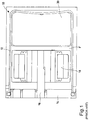
- a gear pump made according to the present invention is shown, still wholly indicated with reference numeral 10.
- the pump 10 comprises most of the technical components of known magnetically-driven gear pumps described so far.
- the pump 10 is provided with at least one element 20 for compensating the pressure/volume at least partially manufactured with a shape memory metal alloy having superelastic properties.
- the element 20 for compensating the pressure/volume comprises a first wall 22, manufactured with a shape memory metal alloy having superelastic properties and configured to be placed in direct contact with the fluid F flowing inside the casing 12.
- the element 20 for compensating the pressure/volume also comprises a second wall 24 manufactured with a non-deformable material, typically metallic, like for example steel. Between the first deformable wall 22 and the second non-deformable wall 24 a chamber 26 is obtained that is configured to form a hollow cavity, inside which the superelastic material that constitutes the first wall 22 can deform in critical load conditions. As shown in figure 3 , the second non-deformable wall 24 is configured to be placed in direct contact with a wall inside the casing 12.
- both the first deformable wall 22, and the second non-deformable wall 24 are made in the form of discs mutually coupled through calking. At least one sealing ring 28 of the O-ring type is interposed between the two discs.
- the gear pump provided with a system for compensating the internal pressure according to the present invention achieves the purposes outlined earlier, being advantageous particularly in terms of size with respect to known deformable elements.
- the element 20 for compensating the pressure/volume according to the present invention does not indeed impact upon the normal operation of the pump 10 and, thanks to the ability of the superelastic disc 22 to carry out large deformations whilst being manufactured with a metal alloy, the system is particularly strong and reliable.
- the system for compensating the internal pressure according to the present invention is simple to make, because it is made up of three elements: a disc 22 made of superelastic alloy, a sealing O-ring 28 and a drawn and calked counter-disc 24, manufactured in simple steel.
- a small hollow cavity 26 is formed, ensured by the static O-ring seal, inside which the superelastic disc 22 can deform, compensating for the increase in volume due to the expansion of the fluid by freezing. Therefore, the uncontrolled rise in pressure is avoided through a reliable and compact system, which still remains rigid in the operating steps at nominal pressure of the pump 10.
- the gear pump provided with a system for compensating the internal pressure of the present invention thus conceived can in any case undergo numerous modifications and variants, all of which are covered by the same inventive concept; moreover, all of the details can be replaced by technically equivalent elements.
- the materials used, as well as the shapes and sizes, can be whatever according to the technical needs.
Landscapes
- Engineering & Computer Science (AREA)
- Mechanical Engineering (AREA)
- General Engineering & Computer Science (AREA)
- Details And Applications Of Rotary Liquid Pumps (AREA)
- Rotary Pumps (AREA)
Claims (10)
- Pumpe (10), umfassend ein Gehäuse (12), das eine Pumpengruppe (14), wenigstens eine Einlassleitung zum Einlassen eines Fluids (F) und wenigstens eine Auslassleitung zum Auslassen des Fluids (F) umschließt, die in dem Gehäuse (12) herausgearbeitet sind, wobei die Pumpengruppe (14) ein Paar von miteinander gekoppelten Zahnrädern umfasst, die jeweils auf einer jeweiligen Stützwelle montiert sind, wobei die relative Bewegung eines ersten Zahnrads in Bezug auf das zweite Zahnrad eine Pumpenkammer mit variablem Volumen im Inneren der Pumpengruppe (14) definiert, um das Fluid (F) aus der Ansaugleitung anzusaugen und es durch die Ausgabeleitung auszustoßen, wobei eine erste Stützwelle (16) mit einer Betätigungsanordnung (18) wirkverbunden ist, so dass das erste Zahnrad als Antriebszahnrad fungieren kann, um das zweite Zahnrad in Drehung zu versetzen, wobei die Pumpe (10) wenigstens ein Element (20) umfasst, um die Erhöhung des Volumens des Fluids (F) und/oder die Erhöhung der Drücke im Inneren der Pumpe (10) auszugleichen, wobei die Pumpe (10) dadurch gekennzeichnet ist, dass das Element (20) zum Ausgleichen des Drucks/Volumens wenigstens teilweise aus einer Formgedächtnis-Metalllegierung mit superelastischen Eigenschaften hergestellt ist.
- Pumpe (10) nach Anspruch 1, dadurch gekennzeichnet, dass das wenigstens eine Element (20) zum Ausgleichen des Drucks/Volumens eine erste Wand (22) umfasst, die aus einer Formgedächtnis-Metalllegierung mit superelastischen Eigenschaften hergestellt und ausgebildet ist, um in direktem Kontakt mit dem im Inneren des Gehäuses (12) zirkulierenden Fluid (F) angeordnet zu werden.
- Pumpe (10) nach Anspruch 2, dadurch gekennzeichnet, dass das wenigstens eine Element (20) zum Ausgleichen des Drucks/Volumens weiter eine zweite, aus einem nicht verformbaren Material hergestellte Wand (24) umfasst, wobei eine Kammer (26) zwischen der ersten, verformbaren Wand (22) und der zweiten, nicht verformbaren Wand (24) herausgearbeitet ist, die angeordnet ist, um einen Hohlraum zu bilden, in dem das die erste Wand (22) bildende, superelastische Material sich unter kritischen Lastbedingungen verformen kann.
- Pumpe (10) nach Anspruch 3, dadurch gekennzeichnet, dass die zweite, nicht verformbare Wand (24) ausgebildet ist, um in direktem Kontakt mit einer inneren Wand des Gehäuses (12) angeordnet zu werden.
- Pumpe (10) nach Anspruch 3 oder 4, dadurch gekennzeichnet, dass das nicht verformbare Material ein Metallmaterial ist.
- Pumpe (10) nach Anspruch 5, dadurch gekennzeichnet, dass das Metallmaterial Stahl ist.
- Pumpe (10) nach Anspruch 3 bis 6, dadurch gekennzeichnet, dass sowohl die erste verformbare Wand (22) als auch die zweite nicht verformbare Wand (24) in Form von Scheiben hergestellt sind, die durch Verstemmen miteinander gekoppelt sind.
- Pumpe (10) nach Anspruch 7, dadurch gekennzeichnet, dass wenigstens ein Dichtungsring (28) des O-Ring-Typs zwischen den beiden Scheiben eingefügt ist.
- Pumpe nach einem der vorstehenden Ansprüche, dadurch gekennzeichnet, dass die Betätigungsanordnung (18) im Inneren des Gehäuses (12) untergebracht ist.
- Pumpe nach einem der vorstehenden Ansprüche, dadurch gekennzeichnet, dass die Betätigungsanordnung (18) vom magnetischen Typ ist.
Applications Claiming Priority (1)
| Application Number | Priority Date | Filing Date | Title |
|---|---|---|---|
| ITUB2015A003739A ITUB20153739A1 (it) | 2015-09-18 | 2015-09-18 | Pompa provvista di un sistema di compensazione della pressione interna. |
Publications (2)
| Publication Number | Publication Date |
|---|---|
| EP3144531A1 EP3144531A1 (de) | 2017-03-22 |
| EP3144531B1 true EP3144531B1 (de) | 2018-04-18 |
Family
ID=55069998
Family Applications (1)
| Application Number | Title | Priority Date | Filing Date |
|---|---|---|---|
| EP16188469.7A Active EP3144531B1 (de) | 2015-09-18 | 2016-09-13 | Pumpe mit system zur kompensation des innendrucks |
Country Status (3)
| Country | Link |
|---|---|
| US (1) | US10113547B2 (de) |
| EP (1) | EP3144531B1 (de) |
| IT (1) | ITUB20153739A1 (de) |
Families Citing this family (1)
| Publication number | Priority date | Publication date | Assignee | Title |
|---|---|---|---|---|
| US10890179B2 (en) * | 2015-12-24 | 2021-01-12 | Fluid-O-Tech Group S.R.L. | Container assembly for a pump |
Family Cites Families (8)
| Publication number | Priority date | Publication date | Assignee | Title |
|---|---|---|---|---|
| GB1172579A (en) * | 1966-08-15 | 1969-12-03 | Borg Warner | Pressure Loaded Hydraulic Gear Pumps or Motors |
| DE1553008C3 (de) * | 1966-11-29 | 1974-11-14 | Danfoss A/S, Nordborg (Daenemark) | Rotationskolbenpumpe, insbesondere Heizolpumpe |
| US3348492A (en) * | 1966-12-05 | 1967-10-24 | Borg Warner | Reversible wear plate pump |
| US4111614A (en) * | 1977-01-24 | 1978-09-05 | Micropump Corporation | Magnetically coupled gear pump construction |
| EP2000709B1 (de) * | 2007-06-04 | 2009-08-12 | C.R.F. Società Consortile per Azioni | Dichtring |
| EP2191104B1 (de) * | 2007-08-30 | 2019-12-04 | Micropump. Inc. | Pumpen und pumpenköpfe mit innendruckabsorptionsglied |
| ITMI20090188U1 (it) * | 2009-06-08 | 2010-12-09 | Fluid O Tech Srl | Assieme di contenimento per una pompa volumetrica |
| US8734139B2 (en) * | 2010-07-01 | 2014-05-27 | Micropump, Inc. | Pumps and pump heads comprising volume-compensation feature |
-
2015
- 2015-09-18 IT ITUB2015A003739A patent/ITUB20153739A1/it unknown
-
2016
- 2016-09-13 EP EP16188469.7A patent/EP3144531B1/de active Active
- 2016-09-16 US US15/267,333 patent/US10113547B2/en active Active
Non-Patent Citations (1)
| Title |
|---|
| None * |
Also Published As
| Publication number | Publication date |
|---|---|
| ITUB20153739A1 (it) | 2017-03-18 |
| EP3144531A1 (de) | 2017-03-22 |
| US10113547B2 (en) | 2018-10-30 |
| US20170082105A1 (en) | 2017-03-23 |
Similar Documents
| Publication | Publication Date | Title |
|---|---|---|
| JP6471218B2 (ja) | 内部圧力吸収部材を有するポンプ及びポンプヘッド | |
| US11268520B2 (en) | Centrifugal pump with adaptive pump stages | |
| CN102112785B (zh) | 机械密封件 | |
| EP3144531B1 (de) | Pumpe mit system zur kompensation des innendrucks | |
| EP3284940B1 (de) | Dichtung für eine kolbenstange | |
| US20070009367A1 (en) | Close fit cylinder and plunger | |
| US4186929A (en) | Hydraulic pump with an improved sealing arrangement | |
| CN107654381B (zh) | 自冷却真空泵系统 | |
| KR102724762B1 (ko) | 펌프용 메카니컬 씰 | |
| RU94644U1 (ru) | Многоступенчатый насос | |
| EP3480460B1 (de) | Volumetrische pumpe | |
| EP0919724A2 (de) | Hydraulisch angetriebene Doppelmembranpumpe | |
| EP3225846B1 (de) | Elastisches pumpengehäuse | |
| CN107269520A (zh) | 磁力补偿浮动侧板组合件 | |
| EP2921713B1 (de) | Pumpe mit einer schutzeinheit gegen wasserschlag | |
| RU99835U1 (ru) | Вертикальный центробежный насос | |
| CN204961379U (zh) | 一种干式泵轴承支架 | |
| CN204985034U (zh) | 一种干式泵轴承支架 | |
| RU83552U1 (ru) | Крыльчатка насоса системы жидкостного охлаждения двигателя внутреннего сгорания | |
| RU94645U1 (ru) | Центробежный насос | |
| HCP’s | Dewatering range for groundworks | |
| RU70322U1 (ru) | Моноблочный насосный агрегат | |
| KR101687333B1 (ko) | 기어펌프 어셈블리 | |
| RU49908U1 (ru) | Насос для системы охлаждения двигателя внутреннего сгорания | |
| US20210372399A1 (en) | High pressure pump |
Legal Events
| Date | Code | Title | Description |
|---|---|---|---|
| PUAI | Public reference made under article 153(3) epc to a published international application that has entered the european phase |
Free format text: ORIGINAL CODE: 0009012 |
|
| STAA | Information on the status of an ep patent application or granted ep patent |
Free format text: STATUS: THE APPLICATION HAS BEEN PUBLISHED |
|
| AK | Designated contracting states |
Kind code of ref document: A1 Designated state(s): AL AT BE BG CH CY CZ DE DK EE ES FI FR GB GR HR HU IE IS IT LI LT LU LV MC MK MT NL NO PL PT RO RS SE SI SK SM TR |
|
| AX | Request for extension of the european patent |
Extension state: BA ME |
|
| STAA | Information on the status of an ep patent application or granted ep patent |
Free format text: STATUS: REQUEST FOR EXAMINATION WAS MADE |
|
| REG | Reference to a national code |
Ref country code: DE Ref legal event code: R079 Ref document number: 602016002584 Country of ref document: DE Free format text: PREVIOUS MAIN CLASS: F04C0002080000 Ipc: F04C0014200000 |
|
| 17P | Request for examination filed |
Effective date: 20170915 |
|
| RBV | Designated contracting states (corrected) |
Designated state(s): AL AT BE BG CH CY CZ DE DK EE ES FI FR GB GR HR HU IE IS IT LI LT LU LV MC MK MT NL NO PL PT RO RS SE SI SK SM TR |
|
| GRAP | Despatch of communication of intention to grant a patent |
Free format text: ORIGINAL CODE: EPIDOSNIGR1 |
|
| STAA | Information on the status of an ep patent application or granted ep patent |
Free format text: STATUS: GRANT OF PATENT IS INTENDED |
|
| RIC1 | Information provided on ipc code assigned before grant |
Ipc: F04C 23/00 20060101ALI20171017BHEP Ipc: F04C 2/18 20060101ALI20171017BHEP Ipc: F04C 2/08 20060101ALI20171017BHEP Ipc: F04C 2/10 20060101ALI20171017BHEP Ipc: F04C 14/20 20060101AFI20171017BHEP Ipc: F04C 15/00 20060101ALI20171017BHEP |
|
| INTG | Intention to grant announced |
Effective date: 20171107 |
|
| GRAS | Grant fee paid |
Free format text: ORIGINAL CODE: EPIDOSNIGR3 |
|
| GRAA | (expected) grant |
Free format text: ORIGINAL CODE: 0009210 |
|
| STAA | Information on the status of an ep patent application or granted ep patent |
Free format text: STATUS: THE PATENT HAS BEEN GRANTED |
|
| AK | Designated contracting states |
Kind code of ref document: B1 Designated state(s): AL AT BE BG CH CY CZ DE DK EE ES FI FR GB GR HR HU IE IS IT LI LT LU LV MC MK MT NL NO PL PT RO RS SE SI SK SM TR |
|
| REG | Reference to a national code |
Ref country code: GB Ref legal event code: FG4D |
|
| REG | Reference to a national code |
Ref country code: CH Ref legal event code: EP |
|
| REG | Reference to a national code |
Ref country code: AT Ref legal event code: REF Ref document number: 990793 Country of ref document: AT Kind code of ref document: T Effective date: 20180515 |
|
| REG | Reference to a national code |
Ref country code: IE Ref legal event code: FG4D |
|
| REG | Reference to a national code |
Ref country code: DE Ref legal event code: R096 Ref document number: 602016002584 Country of ref document: DE |
|
| REG | Reference to a national code |
Ref country code: NL Ref legal event code: MP Effective date: 20180418 |
|
| REG | Reference to a national code |
Ref country code: LT Ref legal event code: MG4D |
|
| PG25 | Lapsed in a contracting state [announced via postgrant information from national office to epo] |
Ref country code: NL Free format text: LAPSE BECAUSE OF FAILURE TO SUBMIT A TRANSLATION OF THE DESCRIPTION OR TO PAY THE FEE WITHIN THE PRESCRIBED TIME-LIMIT Effective date: 20180418 |
|
| PG25 | Lapsed in a contracting state [announced via postgrant information from national office to epo] |
Ref country code: SE Free format text: LAPSE BECAUSE OF FAILURE TO SUBMIT A TRANSLATION OF THE DESCRIPTION OR TO PAY THE FEE WITHIN THE PRESCRIBED TIME-LIMIT Effective date: 20180418 Ref country code: ES Free format text: LAPSE BECAUSE OF FAILURE TO SUBMIT A TRANSLATION OF THE DESCRIPTION OR TO PAY THE FEE WITHIN THE PRESCRIBED TIME-LIMIT Effective date: 20180418 Ref country code: LT Free format text: LAPSE BECAUSE OF FAILURE TO SUBMIT A TRANSLATION OF THE DESCRIPTION OR TO PAY THE FEE WITHIN THE PRESCRIBED TIME-LIMIT Effective date: 20180418 Ref country code: FI Free format text: LAPSE BECAUSE OF FAILURE TO SUBMIT A TRANSLATION OF THE DESCRIPTION OR TO PAY THE FEE WITHIN THE PRESCRIBED TIME-LIMIT Effective date: 20180418 Ref country code: BG Free format text: LAPSE BECAUSE OF FAILURE TO SUBMIT A TRANSLATION OF THE DESCRIPTION OR TO PAY THE FEE WITHIN THE PRESCRIBED TIME-LIMIT Effective date: 20180718 Ref country code: PL Free format text: LAPSE BECAUSE OF FAILURE TO SUBMIT A TRANSLATION OF THE DESCRIPTION OR TO PAY THE FEE WITHIN THE PRESCRIBED TIME-LIMIT Effective date: 20180418 Ref country code: NO Free format text: LAPSE BECAUSE OF FAILURE TO SUBMIT A TRANSLATION OF THE DESCRIPTION OR TO PAY THE FEE WITHIN THE PRESCRIBED TIME-LIMIT Effective date: 20180718 Ref country code: AL Free format text: LAPSE BECAUSE OF FAILURE TO SUBMIT A TRANSLATION OF THE DESCRIPTION OR TO PAY THE FEE WITHIN THE PRESCRIBED TIME-LIMIT Effective date: 20180418 |
|
| PG25 | Lapsed in a contracting state [announced via postgrant information from national office to epo] |
Ref country code: GR Free format text: LAPSE BECAUSE OF FAILURE TO SUBMIT A TRANSLATION OF THE DESCRIPTION OR TO PAY THE FEE WITHIN THE PRESCRIBED TIME-LIMIT Effective date: 20180719 Ref country code: LV Free format text: LAPSE BECAUSE OF FAILURE TO SUBMIT A TRANSLATION OF THE DESCRIPTION OR TO PAY THE FEE WITHIN THE PRESCRIBED TIME-LIMIT Effective date: 20180418 Ref country code: HR Free format text: LAPSE BECAUSE OF FAILURE TO SUBMIT A TRANSLATION OF THE DESCRIPTION OR TO PAY THE FEE WITHIN THE PRESCRIBED TIME-LIMIT Effective date: 20180418 Ref country code: RS Free format text: LAPSE BECAUSE OF FAILURE TO SUBMIT A TRANSLATION OF THE DESCRIPTION OR TO PAY THE FEE WITHIN THE PRESCRIBED TIME-LIMIT Effective date: 20180418 |
|
| REG | Reference to a national code |
Ref country code: AT Ref legal event code: MK05 Ref document number: 990793 Country of ref document: AT Kind code of ref document: T Effective date: 20180418 |
|
| REG | Reference to a national code |
Ref country code: DE Ref legal event code: R097 Ref document number: 602016002584 Country of ref document: DE |
|
| PG25 | Lapsed in a contracting state [announced via postgrant information from national office to epo] |
Ref country code: CZ Free format text: LAPSE BECAUSE OF FAILURE TO SUBMIT A TRANSLATION OF THE DESCRIPTION OR TO PAY THE FEE WITHIN THE PRESCRIBED TIME-LIMIT Effective date: 20180418 Ref country code: SK Free format text: LAPSE BECAUSE OF FAILURE TO SUBMIT A TRANSLATION OF THE DESCRIPTION OR TO PAY THE FEE WITHIN THE PRESCRIBED TIME-LIMIT Effective date: 20180418 Ref country code: RO Free format text: LAPSE BECAUSE OF FAILURE TO SUBMIT A TRANSLATION OF THE DESCRIPTION OR TO PAY THE FEE WITHIN THE PRESCRIBED TIME-LIMIT Effective date: 20180418 Ref country code: AT Free format text: LAPSE BECAUSE OF FAILURE TO SUBMIT A TRANSLATION OF THE DESCRIPTION OR TO PAY THE FEE WITHIN THE PRESCRIBED TIME-LIMIT Effective date: 20180418 Ref country code: DK Free format text: LAPSE BECAUSE OF FAILURE TO SUBMIT A TRANSLATION OF THE DESCRIPTION OR TO PAY THE FEE WITHIN THE PRESCRIBED TIME-LIMIT Effective date: 20180418 Ref country code: EE Free format text: LAPSE BECAUSE OF FAILURE TO SUBMIT A TRANSLATION OF THE DESCRIPTION OR TO PAY THE FEE WITHIN THE PRESCRIBED TIME-LIMIT Effective date: 20180418 |
|
| PLBE | No opposition filed within time limit |
Free format text: ORIGINAL CODE: 0009261 |
|
| STAA | Information on the status of an ep patent application or granted ep patent |
Free format text: STATUS: NO OPPOSITION FILED WITHIN TIME LIMIT |
|
| PG25 | Lapsed in a contracting state [announced via postgrant information from national office to epo] |
Ref country code: SM Free format text: LAPSE BECAUSE OF FAILURE TO SUBMIT A TRANSLATION OF THE DESCRIPTION OR TO PAY THE FEE WITHIN THE PRESCRIBED TIME-LIMIT Effective date: 20180418 Ref country code: IT Free format text: LAPSE BECAUSE OF FAILURE TO SUBMIT A TRANSLATION OF THE DESCRIPTION OR TO PAY THE FEE WITHIN THE PRESCRIBED TIME-LIMIT Effective date: 20180418 |
|
| 26N | No opposition filed |
Effective date: 20190121 |
|
| PG25 | Lapsed in a contracting state [announced via postgrant information from national office to epo] |
Ref country code: MC Free format text: LAPSE BECAUSE OF FAILURE TO SUBMIT A TRANSLATION OF THE DESCRIPTION OR TO PAY THE FEE WITHIN THE PRESCRIBED TIME-LIMIT Effective date: 20180418 |
|
| PG25 | Lapsed in a contracting state [announced via postgrant information from national office to epo] |
Ref country code: SI Free format text: LAPSE BECAUSE OF FAILURE TO SUBMIT A TRANSLATION OF THE DESCRIPTION OR TO PAY THE FEE WITHIN THE PRESCRIBED TIME-LIMIT Effective date: 20180418 |
|
| REG | Reference to a national code |
Ref country code: BE Ref legal event code: MM Effective date: 20180930 |
|
| REG | Reference to a national code |
Ref country code: IE Ref legal event code: MM4A |
|
| PG25 | Lapsed in a contracting state [announced via postgrant information from national office to epo] |
Ref country code: LU Free format text: LAPSE BECAUSE OF NON-PAYMENT OF DUE FEES Effective date: 20180913 |
|
| PG25 | Lapsed in a contracting state [announced via postgrant information from national office to epo] |
Ref country code: IE Free format text: LAPSE BECAUSE OF NON-PAYMENT OF DUE FEES Effective date: 20180913 |
|
| PG25 | Lapsed in a contracting state [announced via postgrant information from national office to epo] |
Ref country code: FR Free format text: LAPSE BECAUSE OF NON-PAYMENT OF DUE FEES Effective date: 20180930 Ref country code: BE Free format text: LAPSE BECAUSE OF NON-PAYMENT OF DUE FEES Effective date: 20180930 |
|
| PG25 | Lapsed in a contracting state [announced via postgrant information from national office to epo] |
Ref country code: MT Free format text: LAPSE BECAUSE OF NON-PAYMENT OF DUE FEES Effective date: 20180913 |
|
| PG25 | Lapsed in a contracting state [announced via postgrant information from national office to epo] |
Ref country code: TR Free format text: LAPSE BECAUSE OF FAILURE TO SUBMIT A TRANSLATION OF THE DESCRIPTION OR TO PAY THE FEE WITHIN THE PRESCRIBED TIME-LIMIT Effective date: 20180418 |
|
| PG25 | Lapsed in a contracting state [announced via postgrant information from national office to epo] |
Ref country code: PT Free format text: LAPSE BECAUSE OF FAILURE TO SUBMIT A TRANSLATION OF THE DESCRIPTION OR TO PAY THE FEE WITHIN THE PRESCRIBED TIME-LIMIT Effective date: 20180418 |
|
| REG | Reference to a national code |
Ref country code: CH Ref legal event code: PL |
|
| PG25 | Lapsed in a contracting state [announced via postgrant information from national office to epo] |
Ref country code: HU Free format text: LAPSE BECAUSE OF FAILURE TO SUBMIT A TRANSLATION OF THE DESCRIPTION OR TO PAY THE FEE WITHIN THE PRESCRIBED TIME-LIMIT; INVALID AB INITIO Effective date: 20160913 Ref country code: MK Free format text: LAPSE BECAUSE OF NON-PAYMENT OF DUE FEES Effective date: 20180418 Ref country code: CY Free format text: LAPSE BECAUSE OF FAILURE TO SUBMIT A TRANSLATION OF THE DESCRIPTION OR TO PAY THE FEE WITHIN THE PRESCRIBED TIME-LIMIT Effective date: 20180418 |
|
| PG25 | Lapsed in a contracting state [announced via postgrant information from national office to epo] |
Ref country code: CH Free format text: LAPSE BECAUSE OF NON-PAYMENT OF DUE FEES Effective date: 20190930 Ref country code: LI Free format text: LAPSE BECAUSE OF NON-PAYMENT OF DUE FEES Effective date: 20190930 Ref country code: IS Free format text: LAPSE BECAUSE OF FAILURE TO SUBMIT A TRANSLATION OF THE DESCRIPTION OR TO PAY THE FEE WITHIN THE PRESCRIBED TIME-LIMIT Effective date: 20180818 |
|
| GBPC | Gb: european patent ceased through non-payment of renewal fee |
Effective date: 20200913 |
|
| PG25 | Lapsed in a contracting state [announced via postgrant information from national office to epo] |
Ref country code: GB Free format text: LAPSE BECAUSE OF NON-PAYMENT OF DUE FEES Effective date: 20200913 |
|
| PGFP | Annual fee paid to national office [announced via postgrant information from national office to epo] |
Ref country code: DE Payment date: 20250702 Year of fee payment: 10 |