EP3144551B1 - Dispositif de déplacement - Google Patents
Dispositif de déplacement Download PDFInfo
- Publication number
- EP3144551B1 EP3144551B1 EP15792681.7A EP15792681A EP3144551B1 EP 3144551 B1 EP3144551 B1 EP 3144551B1 EP 15792681 A EP15792681 A EP 15792681A EP 3144551 B1 EP3144551 B1 EP 3144551B1
- Authority
- EP
- European Patent Office
- Prior art keywords
- piece
- moving body
- passage
- accommodation portion
- block
- Prior art date
- Legal status (The legal status is an assumption and is not a legal conclusion. Google has not performed a legal analysis and makes no representation as to the accuracy of the status listed.)
- Active
Links
Images






Classifications
-
- F—MECHANICAL ENGINEERING; LIGHTING; HEATING; WEAPONS; BLASTING
- F16—ENGINEERING ELEMENTS AND UNITS; GENERAL MEASURES FOR PRODUCING AND MAINTAINING EFFECTIVE FUNCTIONING OF MACHINES OR INSTALLATIONS; THERMAL INSULATION IN GENERAL
- F16C—SHAFTS; FLEXIBLE SHAFTS; ELEMENTS OR CRANKSHAFT MECHANISMS; ROTARY BODIES OTHER THAN GEARING ELEMENTS; BEARINGS
- F16C29/00—Bearings for parts moving only linearly
- F16C29/04—Ball or roller bearings
- F16C29/06—Ball or roller bearings in which the rolling bodies circulate partly without carrying load
- F16C29/0614—Ball or roller bearings in which the rolling bodies circulate partly without carrying load with a shoe type bearing body, e.g. a body facing one side of the guide rail or track only
- F16C29/0621—Ball or roller bearings in which the rolling bodies circulate partly without carrying load with a shoe type bearing body, e.g. a body facing one side of the guide rail or track only for supporting load in essentially two directions, e.g. by multiple points of contact or two rows of rolling elements
- F16C29/0623—Ball or roller bearings in which the rolling bodies circulate partly without carrying load with a shoe type bearing body, e.g. a body facing one side of the guide rail or track only for supporting load in essentially two directions, e.g. by multiple points of contact or two rows of rolling elements with balls
-
- F—MECHANICAL ENGINEERING; LIGHTING; HEATING; WEAPONS; BLASTING
- F16—ENGINEERING ELEMENTS AND UNITS; GENERAL MEASURES FOR PRODUCING AND MAINTAINING EFFECTIVE FUNCTIONING OF MACHINES OR INSTALLATIONS; THERMAL INSULATION IN GENERAL
- F16C—SHAFTS; FLEXIBLE SHAFTS; ELEMENTS OR CRANKSHAFT MECHANISMS; ROTARY BODIES OTHER THAN GEARING ELEMENTS; BEARINGS
- F16C29/00—Bearings for parts moving only linearly
- F16C29/04—Ball or roller bearings
- F16C29/06—Ball or roller bearings in which the rolling bodies circulate partly without carrying load
-
- F—MECHANICAL ENGINEERING; LIGHTING; HEATING; WEAPONS; BLASTING
- F16—ENGINEERING ELEMENTS AND UNITS; GENERAL MEASURES FOR PRODUCING AND MAINTAINING EFFECTIVE FUNCTIONING OF MACHINES OR INSTALLATIONS; THERMAL INSULATION IN GENERAL
- F16C—SHAFTS; FLEXIBLE SHAFTS; ELEMENTS OR CRANKSHAFT MECHANISMS; ROTARY BODIES OTHER THAN GEARING ELEMENTS; BEARINGS
- F16C29/00—Bearings for parts moving only linearly
- F16C29/04—Ball or roller bearings
- F16C29/06—Ball or roller bearings in which the rolling bodies circulate partly without carrying load
- F16C29/0602—Details of the bearing body or carriage or parts thereof, e.g. methods for manufacturing or assembly
- F16C29/0604—Details of the bearing body or carriage or parts thereof, e.g. methods for manufacturing or assembly of the load bearing section
- F16C29/0607—Details of the bearing body or carriage or parts thereof, e.g. methods for manufacturing or assembly of the load bearing section of parts or members for retaining the rolling elements, i.e. members to prevent the rolling elements from falling out of the bearing body or carriage
-
- F—MECHANICAL ENGINEERING; LIGHTING; HEATING; WEAPONS; BLASTING
- F16—ENGINEERING ELEMENTS AND UNITS; GENERAL MEASURES FOR PRODUCING AND MAINTAINING EFFECTIVE FUNCTIONING OF MACHINES OR INSTALLATIONS; THERMAL INSULATION IN GENERAL
- F16C—SHAFTS; FLEXIBLE SHAFTS; ELEMENTS OR CRANKSHAFT MECHANISMS; ROTARY BODIES OTHER THAN GEARING ELEMENTS; BEARINGS
- F16C29/00—Bearings for parts moving only linearly
- F16C29/04—Ball or roller bearings
- F16C29/06—Ball or roller bearings in which the rolling bodies circulate partly without carrying load
- F16C29/0602—Details of the bearing body or carriage or parts thereof, e.g. methods for manufacturing or assembly
- F16C29/0609—Details of the bearing body or carriage or parts thereof, e.g. methods for manufacturing or assembly of the ends of the bearing body or carriage where the rolling elements change direction, e.g. end caps
-
- F—MECHANICAL ENGINEERING; LIGHTING; HEATING; WEAPONS; BLASTING
- F16—ENGINEERING ELEMENTS AND UNITS; GENERAL MEASURES FOR PRODUCING AND MAINTAINING EFFECTIVE FUNCTIONING OF MACHINES OR INSTALLATIONS; THERMAL INSULATION IN GENERAL
- F16C—SHAFTS; FLEXIBLE SHAFTS; ELEMENTS OR CRANKSHAFT MECHANISMS; ROTARY BODIES OTHER THAN GEARING ELEMENTS; BEARINGS
- F16C43/00—Assembling bearings
- F16C43/04—Assembling rolling-contact bearings
Definitions
- the present invention relates to a movement device.
- a movement device such as a linear guide includes a track body, a moving body, and a roller.
- the moving body includes a load roller rolling passage, a no-load roller rolling passage, and a roller direction-change passage.
- the moving body is formed by mounting a cover body on both end surfaces of a moving body main body.
- the roller endlessly circulates between the track body and the moving body, and the track body and the moving body move relative to each other.
- Roller direction-change passages are formed in both the moving body main body and the cover body in the moving body.
- Patent Document 1 discloses a moving body in which an inner peripheral portion of a roller direction-change passage is formed on an end surface of a moving body main body and an outer peripheral portion of the roller direction-change passage is formed in a cover body mounted on the end surface.
- JP H07317762 A shows a movement device according to the preamble of claim 1.
- Patent Document 1 Japanese Examined Patent Application, Second Publication No. H 1-44925
- Mating surfaces of the inner peripheral portion and the outer peripheral portion of the roller direction-change passage disclosed in Patent Document 1 are flat surfaces. Accordingly, when the moving body is assembled, it is necessary to perform positioning adjustment between the moving body main body and the cover body, and much time is required to perform the assembly.
- the connection portions are chamfered, and corners which become steps are rounded. Accordingly, if the roller collides with the chamfered portions, there is a concern that positional deviation between the moving body main body and the cover body may occur due to a great collision load generated at the time of the collision.
- the cover body is attached to the end surface of the moving body main body using only one bolt, and the position of the cover body may easily deviate in a direction in which the cover body rotates about the bolt of the moving body.
- An object of the present invention is to provide a movement device capable of improving assembling characteristics of a moving body and preventing positional deviation between a moving body main body and a cover body when the movement device receives a collision load or the like.
- the movement device of the aspect of the present invention it is possible to improve assembling characteristics of the moving body, and it is possible to prevent positional deviation between the moving body main body and the cover body when the movement device receives a collision load or the like.
- a linear guide 1 according to an embodiment of the present invention will be described with reference to the drawings.
- FIG. 1 is a perspective view showing the linear guide 1 according to the embodiment of the present invention.
- FIG. 2 is a front view (a partially sectional view) showing the linear guide 1.
- the linear guide (movement device) 1 includes a track rail 10 and a slider 20.
- the linear guide (movement device) 1 which includes a pair of track rails 10 and multiple (four) sliders 20 is described.
- the number of the track rails 10 and the sliders 20 may be appropriately modified according to the use or the like.
- sliders 20 are mounted on the pair of track rails 10 so as to be movable relative to the track rails 10 along the pair of track rails 10. Two sliders 20 are mounted on one track rail 10. Four sliders 20 are connected to each other via a connection member or the like (not shown).
- a direction (movement direction of the slider 20) in which the track rail 10 extends is referred to as an X direction.
- a direction in which the track rail 10 and the slider 20 overlap each other is referred to as a Y direction (thickness direction).
- a direction perpendicular to the X direction and the Y direction is referred to as a Z direction (width direction).
- the X direction, the Y direction, and the Z direction are perpendicular to each other.
- the center of the slider 20 in the X direction indicates the direction which is toward a screw hole 33 of the block 21, and the outside of the slider 20 in the X direction indicates the direction which is separated from the screw hole 33 of the block 21.
- the center of the slider 20 in the Y direction or the Z direction is the direction which is toward the screw hole 32 of the block 21, and the outside of the slider 20 in the Y direction or the Z direction indicates the direction which is separated from the screw hole 32 of the block 21.
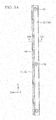
- FIG. 3A is a top view showing the track rail 10
- FIG. 3B is a sectional view taken along line IIIb-IIIb of the track rail 10 of FIG. 3A .
- the pair of the track rails 10 have a shape which is linearly symmetrical in the X direction.
- a track rail 10A (refer to FIG. 1 ) of the pair of track rails 10 will be described.
- the track rail (track body) 10 is a steel member which extends in the X direction, and a cross-section of the track rail 10 perpendicular to the X direction is formed in an approximately rectangular shape.
- a protrusion portion 15 which has an approximately triangular shape in a cross-section perpendicular to the X direction and protrudes in the +Y direction is provided on an inner surface 11 facing the +Y direction of the outer peripheral surfaces of the track rail 10A.
- a pair of roller rolling surfaces 16 extending in the X direction are provided on the protrusion portion 15. The pair of roller rolling surfaces 16 are formed so as to be back to back to each other at approximately 90° in the protrusion portion 15.
- Multiple bolt attachment holes 18 penetrating the track rail 10A in the Z direction are provided with gaps in the X direction in the track rail 10A.
- the track rail 10A is fixed (installed) to a base member or the like (not shown) by bolts (not shown) inserted into the bolt attachment holes 18.
- the two track rails 10 are installed to be parallel to each other such that the inner surfaces 11 face each other.
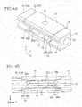
- FIG. 4A is a perspective view showing the slider 20, and FIG. 4B is an inner side view thereof.
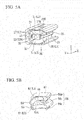
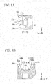
- FIG. 5A is a perspective view showing the block 21, and FIG. 5B is a perspective view showing the end plate 41.
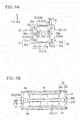
- FIG. 6A is a front view showing the block 21, FIG. 6B is a sectional view taken along line VIIIb-VIIIb of the block 21 of FIG. 6A , and FIG. 6C is a sectional view taken along line VIIIc-VIIIc.
- FIG. 7A is a front view showing the end plate 41
- FIG. 7B is a top view thereof
- FIG. 7C is an inner side view thereof
- FIG. 7D is a rear view thereof.
- the four sliders (moving bodies) 20 have the same shape as each other.
- a slider 20A (refer to FIG. 1 ) among the four sliders 20 will be described.
- the pair of end plates 41 have the same shape as each other.
- an end plate 41A (refer to FIGS. 4A and 4B ) among the pair of end plates 41 will be described.
- the slider 20 includes a rectangular parallelepiped block 21, the pair of end plates 41, or the like.
- the pair of end plates 41 are attached to both end surfaces 22 of the block 21 in the X direction.
- the slider 20 further includes multiple balls 60.
- Two endless circulation passages L which are endless oblong spaces or endless elliptical spaces are formed inside the slider 20.
- the multiple balls 60 are held so as to be rolled inside the two endless circulation passages L.
- Each of the endless circulation passage L is configured of a pair of linear portions extending in the X direction, and a pair of semicircular curved portions which connects end portions of the pair of linear portions to each other.
- One of the linear portions is a load roller passage L1, and the other thereof is a no-load roller passage L2.
- the pair of semicircular curved portions are roller direction-change passages L3.
- the block (moving body main body) 21 is a metal member extending in the X direction and has an approximately rectangular shape in a cross-section perpendicular to the X direction.
- the protrusion portion 15 of the track rail 10 is disposed so as to have a slight gap with respect to the recessed portion 25.
- a pair of roller rolling surfaces 26 extending in the X direction are provided on the recessed portion 25.
- the pair of roller rolling surfaces 26 are formed so as to be back to back to each other at approximately 90° in the recessed portion 25.
- Two circular no-load roller passages L2 (through holes 27) extending in the X direction are formed so as to penetrate the block 21.
- the direction-change passage inner peripheral surface 31 is formed so as to continuously connect the roller rolling surface 26 (load roller passage L1) and the no-load roller passage L2 to each other.
- the two roller rolling surfaces 16 of the track rail 10 and the two roller rolling surfaces 26 of the block 21 are disposed so as to face each other.
- a space (a circular hole extending in the X direction) which is formed between each of the roller rolling surfaces 16 and each of the roller rolling surfaces 26 becomes the load roller passage L1.
- the end plate (cover body) 41 is a flat-plated resin molded member and is fixed to the end surface 22 of the block 21.
- the end plate 41 has an approximately rectangular shape in a cross-section perpendicular to the X direction.
- a recessed portion 45 which faces the protrusion portion 15 of the track rail 10 and is recessed in the +Y direction so as to have an approximately triangular shape in a cross-section perpendicular to the X direction, is provided on an inner surface 43 of the end plate 41 in the X direction.
- the protrusion portion 15 of the track rail 10 is disposed so as to have a slight gap with respect to the recessed portion 45.
- a rear surface (facing surface) 44 of the end plate 41 is a surface which faces the end surface 22 of the block 21.
- the direction-change passage inner peripheral surface 31 of the block 21 and the direction-change passage outer peripheral surface 51 of the end plate 41 are overlapped so as to face each other.
- the direction-change passage outer peripheral surface 51 is coupled so as to continuously connect the load roller passage L1 and the no-load roller passage L2 of the block 21 to each other.
- a space (a circular hole which is bent in a semicircular shape), which is formed of the direction-change passage inner peripheral surface 31 and the direction-change passage outer peripheral surface 51, becomes the roller direction-change passage L3.
- a ball (roller) 40 is a metal spherical member. Multiple balls 60 are interposed between (load roller passage L1) the track rail 10 and the slider 20, and cause the slider 20 to smoothly move with respect to the track rail 10.
- the multiple balls 60 are disposed inside the endless circulation passage L with almost no gaps, and circulate through the endless circulation passage L.
- the slider 20 is supported so as to be reciprocated along the track rail 10 via the multiple balls 60.
- the shape of the end surface 22 facing the +X direction is the same as the shape of the end surface 22 facing the -X direction.
- the shape of an end surface 22A (refer to FIG. 5A ) of the block 21 facing the -X direction will be described.
- a screw hole 32 is provided on the center of the end surface 22A of the block 21.
- a bolt (not shown) is screwed to the screw hole 32 when the end plate 41A is attached.
- Two no-load roller passages L2 (through holes 27) are open in the +Y direction of the end surface 22A so as to be arranged in the Z direction.
- Two load roller passages L1 (roller rolling surfaces 26) are open in the -Y direction of the end surface 22A so as to be arranged in the Z direction.
- the two roller rolling surfaces 26 are open in an arc shape at an angle exceeding 180° on the end surface 22A.
- Two direction-change passage inner peripheral surfaces 31 of the two roller direction-change passages L3 is opened (exposed) to the end surface 22A in the Y direction.
- the two direction-change passage inner peripheral surfaces 31 are formed so as to be linearly symmetrical on both side in the Z direction in a state where the screw hole 32 is interposed therebetween.
- the two discharge-change passage inner peripheral surfaces 31 are bent in arc shapes.
- Each of the two direction-change passage inner peripheral surfaces 31 includes a linear shape (inner peripheral surface 31f) at the center of the end surface 22A in the Y direction, and arc shapes (inner peripheral surfaces 31g) on the outer sides of the end surface 22A in the Y direction.
- the direction-change passage inner peripheral surface 31 is continuously connected to the through hole 27 and the roller rolling surface 26.
- two load roller passages L1 (roller rolling surfaces 26) are linearly formed on the recessed portion 25 in the X direction.
- the direction-change passage inner peripheral surface 31 (inner peripheral surface 31g) of the roller direction-change passage L3 is continuously connected to each of both ends of the roller rolling surfaces 26.
- the direction-change passage inner peripheral surface 31 (inner peripheral surface 31g) is gradually directed toward the outside in the Z direction as it is directed toward the outside in the X direction with respect to the recessed portion 25. That is, the two direction-change passage inner peripheral surfaces 31 are directed in the direction separated from each other.
- the screw hole 33 is provided at the center of the block 21.
- a bolt (not shown) is screwed to the screw hole 33 when a connection member or the like (not shown) is attached to the block 21 (slider 20).
- the no-load roller passage L2 (through hole 27) is linearly formed in the X direction in the +Y direction of the block 21.
- the load roller passage L1 (roller rolling surface 26) is linearly formed in the X direction in the -Y direction of the block 21.
- the direction-change passage inner peripheral surface 31 (inner peripheral surface 31g) of the roller direction-change passage L3 is continuously connected to each of both ends of the load roller passage L1 and the no-load roller passage L2.
- the direction-change passage inner peripheral surface 31 (inner peripheral surface 31g) is formed so as to be gradually directed toward the center (inner peripheral surface 31f) in the Y direction as it is directed toward the outside in the X direction.
- the direction-change passage inner peripheral surface 31 of the roller direction-change passage L3 is viewed in the Z direction, the direction-change passage inner peripheral surface 31 is formed in a semicircular curved shape which is continuously connected to the load roller passage L1 (roller rolling surface 26) and the no-load roller passage L2 (through hole 27).
- the center (inner peripheral surface 31f) of the direction-change passage inner peripheral surface 31 is formed in a linear shape, and the outer side (inner peripheral surface 31g) thereof is curved in an arc shape.
- a space (guide piece accommodation portion (circulation piece accommodation portion) 35) which is formed so as to be recessed from the end surface 22A in the X direction is provided outside the through hole 27 and the inner peripheral surface 31g.
- the guide piece accommodation portion 35 is formed in a shape in which two arcs are connected to each other.
- the guide piece accommodation portion 35 is formed along the inner peripheral surface 31g, the guide piece accommodation portion 35 is formed so as to be gradually cut more deeply in the X direction as it is directed toward the outside in the Y direction.
- the scooping piece accommodation portion 36 is provided outside the roller rolling surface 26 in the Z direction.
- the second abutment surface (tip surface) 56t abuts on the second abutment surface 36t of the scooping piece accommodation portion 36 of the block 21.
- the guide piece 55 is formed so as to further protrude in the +X direction than the scooping piece 56. That is, the guide piece 55 on the no-load roller passage L2 is provided so as to further protrude than the scooping piece 56 on the load roller passage L1 side. Accordingly, when the end plate 41 is attached to the block 21, the guide piece 55 is accommodated in the guide piece accommodation portion 35 before the scooping piece 56 is accommodated in the scooping piece accommodation portion 36. Accordingly, when the end plate 41 is attached to the block 21, the guide piece 55 and the guide piece accommodation portion 35 function as guide mechanisms.
- inclined surfaces 58A and 58B which gradually protrude in the +X direction are respectively provided on the outsides of the two positioned members 57A and 57B in the Y direction.
- the inclined surface 58A is formed such that the positioned member 57A and the guide piece 55 are integrally connected with respect to each other.
- the sliding surface 35s (guide piece accommodation portion 35) which is formed in a shape in which two arcs are connected to each other is provided on the outer peripheral side of the through hole 27. Accordingly, the ball 60 which has been inserted into one through hole 27 is not inserted into the other adjacent through hole 27. Since the ball 60 which has been inserted into one through hole 27 falls along the sliding surface 35s, the ball is not falsely inserted into the other adjacent through hole 27.
- the pair of positioned members 57A and 57B of the end plate 41A are fitted to the pair of positioning members 37A and 37B of the block 21. Since the positioned members 57A and 57B are fitted to the positioning members 37A and 37B, the end plate 41A is positioned to the block 21. Accordingly, the movement in the Y direction and the rotation in the X direction of the end plate 41A with respect to the block 21 are prevented.
- the outer surface 56s of the outer piece 56p of the scooping piece 56 abuts on the first abutment surface 36s of the scooping piece accommodation portion 36. Simultaneously, the tip surface 56t of the outer piece 56p of the scooping piece 56 abuts on the second abutment surface 36t of the scooping piece accommodation portion 36.
- the outer piece 56p of the scooping piece 56 receives forces directed to the outsides in the Y direction and the Z direction from the balls 60.
- the outer piece 56p of the scooping piece 56 is accommodated in the scooping piece accommodation portion 36 of the block 21.
- the outer surface 56s abuts on the first abutment surface 36s, and the tip surface 56t abuts on the second abutment surface 36t. Accordingly, even when the outer piece 56p of the scooping piece 56 receives the forces from the balls 60, the outer piece 56p is supported by the scooping piece accommodation portion 36 (first abutment surface 36s and second abutment surface 36t). Accordingly, the outer piece 56p is not damaged (deformed). In addition, the balls 60 do not fall from the endless circulation passage L.
- the center piece 56q of the scooping piece 56 is not accommodated in the scooping piece accommodation portion 36.
- the inclined surface 38B is provided on the block 21. Accordingly, the center piece 56q can be formed so as to be gradually thickened toward the side opposite to the side on which the center piece 56q protrudes toward the block 21. Accordingly, even when the center piece 56q of the scooping piece 56 receives the forces from the balls 60, the center piece 56q is not damaged (deformed). Therefore, the balls 60 do not fall from the endless circulation passage L.
- the end plate 41 is positioned to the block 21. Accordingly, the direction-change passage inner peripheral surface 31 and the direction-change passage outer peripheral surface 51 are overlapped so as to correctly face to each other, and the smooth roller direction-change passage L3 is formed. In addition, the roller direction-change passage L3 is correctly connected to the load roller passage L1 and the no-load roller passage L2, and the endless circulation passage L without steps is formed. Accordingly, it is possible to improve assembling characteristics of the slider 20, and it is possible to prevent positional deviation between the block 21 and the end plate 41 due to a collision load or the like.
- the roller is not limited to the roller, and may be a ball.
- a retainer may not be provided.
Landscapes
- Engineering & Computer Science (AREA)
- General Engineering & Computer Science (AREA)
- Mechanical Engineering (AREA)
- Bearings For Parts Moving Linearly (AREA)
Claims (4)
- Dispositif de déplacement (1) comprenant :un corps de parcours (10) ; etun corps mobile qui comprend :
une pluralité de passages de circulation sans fin (L) ; et des rouleaux (60) configurés pour rouler dans la pluralité de passages de circulation sans fin (L), le corps mobile (20) étant mobile par rapport au corps de parcours (10) via les rouleaux (60) disposés entre le corps de parcours (10) et le corps mobile (20), dans lequel le corps mobile (20) comprend en outre :un corps principal de corps mobile (21) dans lequel des parties périphériques intérieures (31) de passages de changement de direction de rouleau (L3) configurant les passages de circulation sans fin adjacents (L) sont formées pour être adjacentes les unes aux autres sur une surface d'extrémité (22) dans une direction de déplacement dans laquelle le corps mobile (20) se déplace ; etun corps de couvercle (41) qui est attaché à la surface d'extrémité (22) du corps principal de corps mobile (21) et dans lequel des parties périphériques extérieures (51) de passages de changement de direction de rouleau (L3) configurant les passages de circulation sans fin adjacents (L) sont formées pour être adjacentes les unes aux autres,dans lequel le corps principal de corps mobile (21) et le corps de couvercle (41) sont positionnés en venant en prise avec une partie de positionnement (37A, 37B) disposée entre les parties périphériques intérieures adjacentes du corps principal de corps mobile (21) avec une partie de positionnement (57A, 57B) entre les parties périphériques extérieures adjacentes du corps de couvercle,dans lequel l'une des parties de positionnement comprend une paire de parties en retrait qui est disposée sur l'un parmi le corps principal de corps mobile (21) et le corps de couvercle (41),dans lequel une autre des parties de positionnement comprend une paire de parties en saillie qui est disposée sur un autre parmi le corps principal de corps mobile (21) et le corps de couvercle (41) et vient buter sur la partie en retrait,dans lequel les parties en retrait définissent deux éléments de positionnement (37A, 37B),dans lequel les parties en saillie définissent deux éléments positionnés (57A, 57B),dans lequel les éléments de positionnement (37A, 37B) et les éléments positionnés (57A, 57B) sont configurés par deux surfaces parallèles l'une à l'autre,dans lequel la paire de parties en retrait est formée de manière à être dos à dos l'une et l'autre sur les deux côtés d'un trou de vis (33) formé dans la surface d'extrémité (22) du corps mobile (20), etdans lequel la paire de parties en saillie est formée de manière à se faire face côté avant l'une et l'autre sur chaque côté d'un trou d'insertion de boulon (52) qui est formé dans une surface arrière du corps de couvercle (41) de manière à pénétrer dans le corps de couvercle (41), dans lequel la surface arrière est adoptée pour faire face à la surface d'extrémité (44) du corps mobile (20),caractérisé en ce que des surfaces inclinées (38A, 38B) sont disposées sur l'extérieur respectif des deux éléments de positionnement (37A, 37B) de telle sorte qu'elles sont connectées à une partie inférieure respective d'un élément de positionnement respectif (37A, 37B), et en ce qued'autres surfaces inclinées (58A, 58B) sont disposées sur l'extérieur respectif des deux éléments positionnés (57A, 57B), de sorte que les autres surfaces inclinées (58A, 58B) sont formées le long des surfaces inclinées (38A, 38B). - Dispositif de déplacement (1) selon la revendication 1, dans lequel
chacun des passages de circulation sans fin (L) comprend un passage de rouleau à charge (L1), un passage de rouleau sans charge (L2), et une partie de logement de pièce de circulation (36), la partie de logement de pièce de circulation (36) étant formée sur au moins au moins l'un parmi le passage de rouleau à charge (L1) et le passage de rouleau sans charge (L2),
le corps de couvercle (41) comprend une pièce de circulation (55) qui fait saillie vers le corps mobile (21), forme une partie de la partie périphérique extérieure, et est logée dans la partie de logement de pièce de circulation (36), et
les parties en saillie sont agencés d'un seul tenant par rapport à la pièce de circulation (55). - Dispositif de déplacement (1) selon la revendication 2, dans lequel
le passage de rouleau sans charge (L2) comprend la partie de logement de pièce de circulation (36) dans laquelle la pièce de circulation (55) est logée, et
la pièce de circulation (55) comprend des surfaces de guidage en forme d'arc qui sont formées à l'extérieur des parties périphériques extérieures adjacentes et sont continues les unes par rapport aux autres. - Dispositif de déplacement (1) selon la revendication 2 ou 3, dans lequel
le passage de rouleau à charge (L1) et le passage de rouleau sans charge (L2) comprennent tous deux la partie de logement de pièce de circulation (36) dans laquelle la pièce de circulation (55) est logée,
la pièce de circulation (55) qui est logée dans la partie de logement de pièce de circulation (36) du passage de rouleau à charge (L1) comprend une partie de ramassage qui ramasse le rouleau dans le passage de changement de direction de rouleau (L3), et
la pièce de circulation (55) qui est logée dans la partie de logement de pièce de circulation (36) du passage de rouleau sans charge (L2) est agencée pour faire saillie depuis la pièce de circulation (55) qui est logée dans la partie de logement de pièce de circulation (36) du passage du rouleau à charge (L1).
Applications Claiming Priority (2)
| Application Number | Priority Date | Filing Date | Title |
|---|---|---|---|
| JP2014101678A JP6162641B2 (ja) | 2014-05-15 | 2014-05-15 | 運動装置 |
| PCT/JP2015/064077 WO2015174528A1 (fr) | 2014-05-15 | 2015-05-15 | Dispositif de déplacement |
Publications (3)
| Publication Number | Publication Date |
|---|---|
| EP3144551A1 EP3144551A1 (fr) | 2017-03-22 |
| EP3144551A4 EP3144551A4 (fr) | 2018-01-17 |
| EP3144551B1 true EP3144551B1 (fr) | 2020-06-24 |
Family
ID=54480063
Family Applications (1)
| Application Number | Title | Priority Date | Filing Date |
|---|---|---|---|
| EP15792681.7A Active EP3144551B1 (fr) | 2014-05-15 | 2015-05-15 | Dispositif de déplacement |
Country Status (5)
| Country | Link |
|---|---|
| US (1) | US9777768B2 (fr) |
| EP (1) | EP3144551B1 (fr) |
| JP (1) | JP6162641B2 (fr) |
| TW (1) | TWI658218B (fr) |
| WO (1) | WO2015174528A1 (fr) |
Families Citing this family (4)
| Publication number | Priority date | Publication date | Assignee | Title |
|---|---|---|---|---|
| USD835492S1 (en) * | 2015-02-24 | 2018-12-11 | Thk Co., Ltd. | Slide rail |
| JP7190298B2 (ja) * | 2018-09-18 | 2022-12-15 | キヤノン株式会社 | 位置決め装置および露光装置 |
| DE102020202872B4 (de) * | 2020-03-06 | 2022-02-03 | Festo Se & Co. Kg | Linearführungseinrichtung |
| JP1696218S (fr) * | 2021-03-29 | 2021-10-04 |
Family Cites Families (21)
| Publication number | Priority date | Publication date | Assignee | Title |
|---|---|---|---|---|
| JPS58142020A (ja) | 1982-02-13 | 1983-08-23 | Hiroshi Teramachi | 無限摺動ベアリングと該ベアリングユニツト |
| JPS5920023U (ja) * | 1982-07-21 | 1984-02-07 | 寺町 博 | 無限摺動ベアリング |
| JPS59208218A (ja) * | 1983-05-11 | 1984-11-26 | Hiroshi Teramachi | 旋回ベアリング |
| JPH03144114A (ja) * | 1990-10-19 | 1991-06-19 | Hiroshi Teramachi | アンギュラー型直線摺動用ベアリング |
| JPH0544724A (ja) * | 1991-08-12 | 1993-02-23 | Koyo Seiko Co Ltd | 直動形ガイド装置 |
| JP3412914B2 (ja) * | 1994-05-20 | 2003-06-03 | Thk株式会社 | 転がり案内装置および転がり案内装置の移動ブロックの製造方法 |
| JP4026864B2 (ja) * | 1995-08-02 | 2007-12-26 | Thk株式会社 | 転がり案内装置 |
| JPH09296821A (ja) * | 1996-05-07 | 1997-11-18 | Thk Kk | 直線案内装置のスライダの製造方法 |
| TW483991B (en) * | 1999-03-31 | 2002-04-21 | Chieftech Prec Co Ltd | Linear motion rolling guide device |
| JP3950686B2 (ja) * | 2001-12-25 | 2007-08-01 | 日本トムソン株式会社 | 転動体間にセパレータを備えた直動案内ユニット |
| JP2004036786A (ja) * | 2002-07-04 | 2004-02-05 | Nsk Ltd | 直動装置 |
| JP4173420B2 (ja) * | 2003-09-04 | 2008-10-29 | 日本精工株式会社 | リニアガイド |
| DE10342841B4 (de) * | 2003-09-17 | 2010-02-25 | Tollo Linear Ab | Wälzkörperführung |
| US20060231335A1 (en) * | 2004-02-06 | 2006-10-19 | Hiwin Technologies Corp. | Lubrication system for a linear guideway |
| US7585112B2 (en) * | 2007-03-20 | 2009-09-08 | Hiwin Technologies Corp. | Linear motion guide apparatus |
| JP2008275069A (ja) * | 2007-04-27 | 2008-11-13 | Nsk Ltd | エンドキャップ及びそれを備えたリニアガイド |
| CN101994759B (zh) * | 2009-08-27 | 2012-11-14 | 上银科技股份有限公司 | 线性滑轨的回流系统 |
| JP2012082879A (ja) * | 2010-10-08 | 2012-04-26 | Thk Co Ltd | 運動案内装置 |
| CN103890424B (zh) * | 2011-11-04 | 2016-10-12 | Thk株式会社 | 运动引导装置 |
| JP5724894B2 (ja) * | 2012-01-31 | 2015-05-27 | 日本精工株式会社 | リニアガイド装置 |
| US9234544B2 (en) * | 2013-11-06 | 2016-01-12 | Hiwin Technologies Corp. | Lubricating structure for linear motion guide apparatus |
-
2014
- 2014-05-15 JP JP2014101678A patent/JP6162641B2/ja active Active
-
2015
- 2015-05-15 TW TW104115699A patent/TWI658218B/zh active
- 2015-05-15 US US15/309,288 patent/US9777768B2/en active Active
- 2015-05-15 EP EP15792681.7A patent/EP3144551B1/fr active Active
- 2015-05-15 WO PCT/JP2015/064077 patent/WO2015174528A1/fr not_active Ceased
Non-Patent Citations (1)
| Title |
|---|
| None * |
Also Published As
| Publication number | Publication date |
|---|---|
| TWI658218B (zh) | 2019-05-01 |
| JP6162641B2 (ja) | 2017-07-12 |
| US20170074318A1 (en) | 2017-03-16 |
| WO2015174528A1 (fr) | 2015-11-19 |
| TW201600743A (zh) | 2016-01-01 |
| JP2015218792A (ja) | 2015-12-07 |
| US9777768B2 (en) | 2017-10-03 |
| EP3144551A4 (fr) | 2018-01-17 |
| EP3144551A1 (fr) | 2017-03-22 |
Similar Documents
| Publication | Publication Date | Title |
|---|---|---|
| EP3144551B1 (fr) | Dispositif de déplacement | |
| CA3089574C (fr) | Dispositif de verification de porte de vehicule | |
| EP3115633B1 (fr) | Dispositif de guidage de mouvement linéaire | |
| US8632248B2 (en) | Linear guide device | |
| EP2634442B1 (fr) | Rail latéral pour dispositif de guidage linéaire et dispositif de guidage linéaire | |
| US10436248B2 (en) | Motion guide device | |
| US20160341247A1 (en) | Linear Motion Guiding Device | |
| TW202314136A (zh) | 有限行程型之直線導引裝置 | |
| US7980763B2 (en) | Motion guide device | |
| US9028148B2 (en) | Motion guide device | |
| US7121723B2 (en) | Linear guide apparatus | |
| JP5672895B2 (ja) | 直動案内装置の仮軸用アタッチメント | |
| CN110494663A (zh) | 运动引导装置 | |
| EP1403541B1 (fr) | Palier à roulement linéaire avec rouleaux retenus dans une cage flexible | |
| US20050115096A1 (en) | Linear guide apparatus | |
| EP3135930B1 (fr) | Dispositif à mouvement | |
| US8419280B2 (en) | Thin slide unit | |
| JPS61274117A (ja) | 直線案内ベアリングのボ−ル保持器 | |
| US11767882B2 (en) | Motion guide apparatus | |
| WO2005038276A1 (fr) | Dispositif de guidage lineaire | |
| US20150016759A1 (en) | Rolling guide device | |
| JP5817190B2 (ja) | リニアガイド装置用サイドシール | |
| TWI712749B (zh) | 具有入料口的扣具 | |
| JP2007285315A (ja) | 直動案内軸受装置のストッパ | |
| JP2008032165A (ja) | リニアガイド装置 |
Legal Events
| Date | Code | Title | Description |
|---|---|---|---|
| STAA | Information on the status of an ep patent application or granted ep patent |
Free format text: STATUS: THE INTERNATIONAL PUBLICATION HAS BEEN MADE |
|
| PUAI | Public reference made under article 153(3) epc to a published international application that has entered the european phase |
Free format text: ORIGINAL CODE: 0009012 |
|
| STAA | Information on the status of an ep patent application or granted ep patent |
Free format text: STATUS: REQUEST FOR EXAMINATION WAS MADE |
|
| 17P | Request for examination filed |
Effective date: 20161108 |
|
| AK | Designated contracting states |
Kind code of ref document: A1 Designated state(s): AL AT BE BG CH CY CZ DE DK EE ES FI FR GB GR HR HU IE IS IT LI LT LU LV MC MK MT NL NO PL PT RO RS SE SI SK SM TR |
|
| AX | Request for extension of the european patent |
Extension state: BA ME |
|
| DAV | Request for validation of the european patent (deleted) | ||
| DAX | Request for extension of the european patent (deleted) | ||
| A4 | Supplementary search report drawn up and despatched |
Effective date: 20171215 |
|
| RIC1 | Information provided on ipc code assigned before grant |
Ipc: F16C 29/06 20060101AFI20171211BHEP Ipc: F16C 43/04 20060101ALI20171211BHEP |
|
| STAA | Information on the status of an ep patent application or granted ep patent |
Free format text: STATUS: EXAMINATION IS IN PROGRESS |
|
| 17Q | First examination report despatched |
Effective date: 20190219 |
|
| GRAP | Despatch of communication of intention to grant a patent |
Free format text: ORIGINAL CODE: EPIDOSNIGR1 |
|
| STAA | Information on the status of an ep patent application or granted ep patent |
Free format text: STATUS: GRANT OF PATENT IS INTENDED |
|
| INTG | Intention to grant announced |
Effective date: 20200203 |
|
| GRAS | Grant fee paid |
Free format text: ORIGINAL CODE: EPIDOSNIGR3 |
|
| GRAA | (expected) grant |
Free format text: ORIGINAL CODE: 0009210 |
|
| STAA | Information on the status of an ep patent application or granted ep patent |
Free format text: STATUS: THE PATENT HAS BEEN GRANTED |
|
| AK | Designated contracting states |
Kind code of ref document: B1 Designated state(s): AL AT BE BG CH CY CZ DE DK EE ES FI FR GB GR HR HU IE IS IT LI LT LU LV MC MK MT NL NO PL PT RO RS SE SI SK SM TR |
|
| REG | Reference to a national code |
Ref country code: GB Ref legal event code: FG4D |
|
| REG | Reference to a national code |
Ref country code: CH Ref legal event code: EP |
|
| REG | Reference to a national code |
Ref country code: AT Ref legal event code: REF Ref document number: 1284179 Country of ref document: AT Kind code of ref document: T Effective date: 20200715 |
|
| REG | Reference to a national code |
Ref country code: DE Ref legal event code: R096 Ref document number: 602015054777 Country of ref document: DE |
|
| REG | Reference to a national code |
Ref country code: IE Ref legal event code: FG4D |
|
| PG25 | Lapsed in a contracting state [announced via postgrant information from national office to epo] |
Ref country code: SE Free format text: LAPSE BECAUSE OF FAILURE TO SUBMIT A TRANSLATION OF THE DESCRIPTION OR TO PAY THE FEE WITHIN THE PRESCRIBED TIME-LIMIT Effective date: 20200624 Ref country code: NO Free format text: LAPSE BECAUSE OF FAILURE TO SUBMIT A TRANSLATION OF THE DESCRIPTION OR TO PAY THE FEE WITHIN THE PRESCRIBED TIME-LIMIT Effective date: 20200924 Ref country code: FI Free format text: LAPSE BECAUSE OF FAILURE TO SUBMIT A TRANSLATION OF THE DESCRIPTION OR TO PAY THE FEE WITHIN THE PRESCRIBED TIME-LIMIT Effective date: 20200624 Ref country code: LT Free format text: LAPSE BECAUSE OF FAILURE TO SUBMIT A TRANSLATION OF THE DESCRIPTION OR TO PAY THE FEE WITHIN THE PRESCRIBED TIME-LIMIT Effective date: 20200624 Ref country code: GR Free format text: LAPSE BECAUSE OF FAILURE TO SUBMIT A TRANSLATION OF THE DESCRIPTION OR TO PAY THE FEE WITHIN THE PRESCRIBED TIME-LIMIT Effective date: 20200925 |
|
| REG | Reference to a national code |
Ref country code: LT Ref legal event code: MG4D |
|
| PG25 | Lapsed in a contracting state [announced via postgrant information from national office to epo] |
Ref country code: BG Free format text: LAPSE BECAUSE OF FAILURE TO SUBMIT A TRANSLATION OF THE DESCRIPTION OR TO PAY THE FEE WITHIN THE PRESCRIBED TIME-LIMIT Effective date: 20200924 Ref country code: LV Free format text: LAPSE BECAUSE OF FAILURE TO SUBMIT A TRANSLATION OF THE DESCRIPTION OR TO PAY THE FEE WITHIN THE PRESCRIBED TIME-LIMIT Effective date: 20200624 Ref country code: RS Free format text: LAPSE BECAUSE OF FAILURE TO SUBMIT A TRANSLATION OF THE DESCRIPTION OR TO PAY THE FEE WITHIN THE PRESCRIBED TIME-LIMIT Effective date: 20200624 Ref country code: HR Free format text: LAPSE BECAUSE OF FAILURE TO SUBMIT A TRANSLATION OF THE DESCRIPTION OR TO PAY THE FEE WITHIN THE PRESCRIBED TIME-LIMIT Effective date: 20200624 |
|
| REG | Reference to a national code |
Ref country code: NL Ref legal event code: MP Effective date: 20200624 |
|
| REG | Reference to a national code |
Ref country code: AT Ref legal event code: MK05 Ref document number: 1284179 Country of ref document: AT Kind code of ref document: T Effective date: 20200624 |
|
| PG25 | Lapsed in a contracting state [announced via postgrant information from national office to epo] |
Ref country code: NL Free format text: LAPSE BECAUSE OF FAILURE TO SUBMIT A TRANSLATION OF THE DESCRIPTION OR TO PAY THE FEE WITHIN THE PRESCRIBED TIME-LIMIT Effective date: 20200624 Ref country code: AL Free format text: LAPSE BECAUSE OF FAILURE TO SUBMIT A TRANSLATION OF THE DESCRIPTION OR TO PAY THE FEE WITHIN THE PRESCRIBED TIME-LIMIT Effective date: 20200624 |
|
| PG25 | Lapsed in a contracting state [announced via postgrant information from national office to epo] |
Ref country code: EE Free format text: LAPSE BECAUSE OF FAILURE TO SUBMIT A TRANSLATION OF THE DESCRIPTION OR TO PAY THE FEE WITHIN THE PRESCRIBED TIME-LIMIT Effective date: 20200624 Ref country code: SM Free format text: LAPSE BECAUSE OF FAILURE TO SUBMIT A TRANSLATION OF THE DESCRIPTION OR TO PAY THE FEE WITHIN THE PRESCRIBED TIME-LIMIT Effective date: 20200624 Ref country code: AT Free format text: LAPSE BECAUSE OF FAILURE TO SUBMIT A TRANSLATION OF THE DESCRIPTION OR TO PAY THE FEE WITHIN THE PRESCRIBED TIME-LIMIT Effective date: 20200624 Ref country code: IT Free format text: LAPSE BECAUSE OF FAILURE TO SUBMIT A TRANSLATION OF THE DESCRIPTION OR TO PAY THE FEE WITHIN THE PRESCRIBED TIME-LIMIT Effective date: 20200624 Ref country code: PT Free format text: LAPSE BECAUSE OF FAILURE TO SUBMIT A TRANSLATION OF THE DESCRIPTION OR TO PAY THE FEE WITHIN THE PRESCRIBED TIME-LIMIT Effective date: 20201026 Ref country code: RO Free format text: LAPSE BECAUSE OF FAILURE TO SUBMIT A TRANSLATION OF THE DESCRIPTION OR TO PAY THE FEE WITHIN THE PRESCRIBED TIME-LIMIT Effective date: 20200624 Ref country code: CZ Free format text: LAPSE BECAUSE OF FAILURE TO SUBMIT A TRANSLATION OF THE DESCRIPTION OR TO PAY THE FEE WITHIN THE PRESCRIBED TIME-LIMIT Effective date: 20200624 Ref country code: ES Free format text: LAPSE BECAUSE OF FAILURE TO SUBMIT A TRANSLATION OF THE DESCRIPTION OR TO PAY THE FEE WITHIN THE PRESCRIBED TIME-LIMIT Effective date: 20200624 |
|
| PG25 | Lapsed in a contracting state [announced via postgrant information from national office to epo] |
Ref country code: PL Free format text: LAPSE BECAUSE OF FAILURE TO SUBMIT A TRANSLATION OF THE DESCRIPTION OR TO PAY THE FEE WITHIN THE PRESCRIBED TIME-LIMIT Effective date: 20200624 Ref country code: SK Free format text: LAPSE BECAUSE OF FAILURE TO SUBMIT A TRANSLATION OF THE DESCRIPTION OR TO PAY THE FEE WITHIN THE PRESCRIBED TIME-LIMIT Effective date: 20200624 Ref country code: IS Free format text: LAPSE BECAUSE OF FAILURE TO SUBMIT A TRANSLATION OF THE DESCRIPTION OR TO PAY THE FEE WITHIN THE PRESCRIBED TIME-LIMIT Effective date: 20201024 |
|
| REG | Reference to a national code |
Ref country code: DE Ref legal event code: R097 Ref document number: 602015054777 Country of ref document: DE |
|
| PG25 | Lapsed in a contracting state [announced via postgrant information from national office to epo] |
Ref country code: DK Free format text: LAPSE BECAUSE OF FAILURE TO SUBMIT A TRANSLATION OF THE DESCRIPTION OR TO PAY THE FEE WITHIN THE PRESCRIBED TIME-LIMIT Effective date: 20200624 |
|
| PLBE | No opposition filed within time limit |
Free format text: ORIGINAL CODE: 0009261 |
|
| STAA | Information on the status of an ep patent application or granted ep patent |
Free format text: STATUS: NO OPPOSITION FILED WITHIN TIME LIMIT |
|
| 26N | No opposition filed |
Effective date: 20210325 |
|
| PG25 | Lapsed in a contracting state [announced via postgrant information from national office to epo] |
Ref country code: SI Free format text: LAPSE BECAUSE OF FAILURE TO SUBMIT A TRANSLATION OF THE DESCRIPTION OR TO PAY THE FEE WITHIN THE PRESCRIBED TIME-LIMIT Effective date: 20200624 |
|
| REG | Reference to a national code |
Ref country code: CH Ref legal event code: PL |
|
| GBPC | Gb: european patent ceased through non-payment of renewal fee |
Effective date: 20210515 |
|
| PG25 | Lapsed in a contracting state [announced via postgrant information from national office to epo] |
Ref country code: CH Free format text: LAPSE BECAUSE OF NON-PAYMENT OF DUE FEES Effective date: 20210531 Ref country code: MC Free format text: LAPSE BECAUSE OF FAILURE TO SUBMIT A TRANSLATION OF THE DESCRIPTION OR TO PAY THE FEE WITHIN THE PRESCRIBED TIME-LIMIT Effective date: 20200624 Ref country code: LU Free format text: LAPSE BECAUSE OF NON-PAYMENT OF DUE FEES Effective date: 20210515 Ref country code: LI Free format text: LAPSE BECAUSE OF NON-PAYMENT OF DUE FEES Effective date: 20210531 |
|
| REG | Reference to a national code |
Ref country code: BE Ref legal event code: MM Effective date: 20210531 |
|
| PG25 | Lapsed in a contracting state [announced via postgrant information from national office to epo] |
Ref country code: IE Free format text: LAPSE BECAUSE OF NON-PAYMENT OF DUE FEES Effective date: 20210515 Ref country code: GB Free format text: LAPSE BECAUSE OF NON-PAYMENT OF DUE FEES Effective date: 20210515 |
|
| PG25 | Lapsed in a contracting state [announced via postgrant information from national office to epo] |
Ref country code: BE Free format text: LAPSE BECAUSE OF NON-PAYMENT OF DUE FEES Effective date: 20210531 |
|
| PG25 | Lapsed in a contracting state [announced via postgrant information from national office to epo] |
Ref country code: HU Free format text: LAPSE BECAUSE OF FAILURE TO SUBMIT A TRANSLATION OF THE DESCRIPTION OR TO PAY THE FEE WITHIN THE PRESCRIBED TIME-LIMIT; INVALID AB INITIO Effective date: 20150515 |
|
| PG25 | Lapsed in a contracting state [announced via postgrant information from national office to epo] |
Ref country code: CY Free format text: LAPSE BECAUSE OF FAILURE TO SUBMIT A TRANSLATION OF THE DESCRIPTION OR TO PAY THE FEE WITHIN THE PRESCRIBED TIME-LIMIT Effective date: 20200624 |
|
| PG25 | Lapsed in a contracting state [announced via postgrant information from national office to epo] |
Ref country code: MK Free format text: LAPSE BECAUSE OF FAILURE TO SUBMIT A TRANSLATION OF THE DESCRIPTION OR TO PAY THE FEE WITHIN THE PRESCRIBED TIME-LIMIT Effective date: 20200624 |
|
| PG25 | Lapsed in a contracting state [announced via postgrant information from national office to epo] |
Ref country code: TR Free format text: LAPSE BECAUSE OF FAILURE TO SUBMIT A TRANSLATION OF THE DESCRIPTION OR TO PAY THE FEE WITHIN THE PRESCRIBED TIME-LIMIT Effective date: 20200624 |
|
| PG25 | Lapsed in a contracting state [announced via postgrant information from national office to epo] |
Ref country code: MT Free format text: LAPSE BECAUSE OF FAILURE TO SUBMIT A TRANSLATION OF THE DESCRIPTION OR TO PAY THE FEE WITHIN THE PRESCRIBED TIME-LIMIT Effective date: 20200624 |
|
| PGFP | Annual fee paid to national office [announced via postgrant information from national office to epo] |
Ref country code: DE Payment date: 20250521 Year of fee payment: 11 |
|
| PGFP | Annual fee paid to national office [announced via postgrant information from national office to epo] |
Ref country code: FR Payment date: 20250528 Year of fee payment: 11 |