EP3144618A1 - Chariot pour lyophilisateurs et lyophilisateur - Google Patents
Chariot pour lyophilisateurs et lyophilisateur Download PDFInfo
- Publication number
- EP3144618A1 EP3144618A1 EP16191639.0A EP16191639A EP3144618A1 EP 3144618 A1 EP3144618 A1 EP 3144618A1 EP 16191639 A EP16191639 A EP 16191639A EP 3144618 A1 EP3144618 A1 EP 3144618A1
- Authority
- EP
- European Patent Office
- Prior art keywords
- drying
- freeze
- carriage
- guides
- drying equipment
- Prior art date
- Legal status (The legal status is an assumption and is not a legal conclusion. Google has not performed a legal analysis and makes no representation as to the accuracy of the status listed.)
- Granted
Links
Images









Classifications
-
- F—MECHANICAL ENGINEERING; LIGHTING; HEATING; WEAPONS; BLASTING
- F26—DRYING
- F26B—DRYING SOLID MATERIALS OR OBJECTS BY REMOVING LIQUID THEREFROM
- F26B25/00—Details of general application not covered by group F26B21/00 or F26B23/00
- F26B25/001—Handling, e.g. loading or unloading arrangements
-
- F—MECHANICAL ENGINEERING; LIGHTING; HEATING; WEAPONS; BLASTING
- F26—DRYING
- F26B—DRYING SOLID MATERIALS OR OBJECTS BY REMOVING LIQUID THEREFROM
- F26B5/00—Drying solid materials or objects by processes not involving the application of heat
- F26B5/04—Drying solid materials or objects by processes not involving the application of heat by evaporation or sublimation of moisture under reduced pressure, e.g. in a vacuum
- F26B5/06—Drying solid materials or objects by processes not involving the application of heat by evaporation or sublimation of moisture under reduced pressure, e.g. in a vacuum the process involving freezing
Definitions
- the invention relates to a freeze dryer slide and a freeze dryer.
- Freeze-drying plants are designed in many cases for discontinuous operation and consist predominantly of a drying chamber and a connected thereto via a closable opening condenser chamber, wherein the material to be dried is received in a plurality of drying vessels, vials, ampoules or trays to carry out drying on a footprint within a drying chamber.
- a plurality of such shelves are arranged vertically displaceable one above the other in a frame at a distance.
- a freeze-drying plant in which the drying vessels are transported on a conveyor belt in a position in front of the inlet opening of the housing of this system, to be subsequently introduced in rows in a direction perpendicular to the feed direction of the conveyor belt for the purpose of carrying out the drying process in the housing.
- a device which consists of two on either side of a located in a loading position extending guides mounted, interconnected by a sliding bar carriage, the sliding bar both set up for insertion of the drying vessels and for pushing out the drying vessels after drying is.
- the sliding bar is thus first pivoted to the inactive position, retracted above the drying vessels in the housing and finally pivoted on the opposite side of the input opening back of the group of drying vessels in its active position, in which it is available for pushing out .
- the problem due to the running over of the drying vessels, in particular due to unavoidable abrasion, is the maintenance of aseptic conditions.
- a slider for rowwise insertion into the housing of the first on a conveyor belt drying vessels in a direction perpendicular to the feed direction of the conveyor belt, a slider is provided, wherein additionally a sliding bar is arranged, which extends parallel to the slide and by means of two laterally along the guided in the loading and unloading position guided chain hoists in the housing and is extendable from this.
- the sliding bar is in turn pivotable about a horizontal axis at its ends between a lowered active, that is, to rest against the group of upstanding drying vessels applied position and a raised inactive, that is to say for driving over the group position.
- a further freeze-drying plant in which for the serial insertion of drying vessels in the system, a retractable into the housing through the inlet opening slider is provided, wherein in the housing inserted group of drying vessels during insertion rests against a likewise retractable into the housing bar, which causes a stabilization of the upright position of the drying vessels.
- the beam is supported at both ends on a respective carriage and at this pivotable between a lower active, applied to the drying vessel position and an upper inactive, for driving over the group of drying vessels position determined.
- the slider and the bar can be moved out of the housing completely. During a pushing out of the drying vessels, the beam acts as an ejector, whereas the slide performs a stabilizing function.
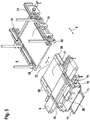
- a freeze-drying plant referred to, inter alia, consisting of a housing 3 arranged in a drying chamber 2 and a slidably mounted on rails 4 in the direction of arrows 5, a loading and unloading device carrying unit 6 is.
- the assembly 6 together with rails and the housing 3 are arranged on a common base plate 7 and it is the assembly 6 - apart from maintenance - usually firmly docked to the housing.
- Carriage 15 receiving guides 16 carries.
- a loading bridge 17 which also carries guides 18 on the upper side, the function of which will be explained below.
- the carriage 15 can be moved along the mutually identical guides 16, 18.
- the guides 16, 18 are dimensioned and arranged in conjunction with the displaceability of the guide unit 14 and the loading bridge 17 in the direction of the arrows 5 with the proviso that the carriage 15 in a front-side limit position or loading position on the side facing away from the housing 3 of the conveyor belt 8 is displaceable.
- the drying chamber 2 is equipped in a conventional manner with an arrangement of mutually parallel, horizontally extending shelves 19 which are held vertically movable in a frame 20 and each serve to set up a drying substance containing drying vessels and after completion of the drying process from the Are to lead out drying chamber 2.
- each of the shelves is movable in this displacement plane.
- This is the height position within the drying chamber in which, with the door open, 12 drying vessels can be introduced or carried out into the drying chamber 2 in a manner which will be explained below, by means of the slide 15.
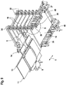
- the top view according Fig. 2 as well as the representation according to Fig. 3 show an adjusting plate 19, which is located in the loading position.
- this displacement plane there are further guides 21, 22, the nature of which corresponds to that of the guides 16, 18.
- the guides 21, 22 are slidably disposed within the housing 3 in its longitudinal direction, whereas their height position is fixed.
- the in Fig. 4 shown, laterally held in the guides 16 carriage 15 is characterized on its front side 23 and on this opposite in the direction of the arrows 5 back 24 by mutually identical guide surfaces, which are intended to bear on the on orparticularlyschiebenden drying vessels.
- the bearing of the carriage 15 in the guides 16 is effected by wheels 25 which are connected by a toothed belt 26 with each other, wherein the timing belt 26 additionally has an external toothing, which with a corresponding profiling of the guides 16 and other guides 18, 21, 22 in Intervention is. All drive and control components of the carriage 15 are housed in a flat housing 27 whose height corresponds approximately to that of the guides 16 and thus less than that of a drying vessel fails.
- a battery-powered electric drive can be used, to charge it in the loading position a non-contact, z.
- B. inductively effective charging station 28 is set up. ( Fig. 1 )
- the width of the surface available for standing up should correspond to an integer multiple of the diameter or a comparable dimension of a drying vessel.
- the individual, pushed onto the loading bridge 17 rows of drying vessels should be laterally offset by half a diameter measure to each other to achieve optimum packing density. In this way, a mutual support effect of the drying vessels can be represented with each other.
- Fig. 5 the loading bridge 17 with side guides 29 and the footprint 19 with side guides 30, 31 equipped. These each form lateral guide edges for the drying vessels and are arranged so as to be displaceable transversely to the insertion direction, thus in the direction of the arrows 32, so that insofar adjustment to different dimensions of the drying vessels is possible.
- each drives are provided for the lateral adjustment of the side guides 29 to 31.
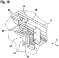
- Each of the shelves 19 is provided in the corner region of its rectangular base with outstanding also rectangular, extending in the plane of the respective footprint 19 lugs 33, each of which is provided with an approximately semicircular, open to the peripheral outside recess 34.
- These recesses 34 serve in conjunction with vertically extending rods 35 of the frame 20 of the vertical guidance of the shelves 19. In this way, an exact vertical guidance of the shelves 19 is shown.
- the longitudinal displaceability of the guides 21, 22 given in this way is set up with the proviso that in an in Fig. 6 shown first boundary position, the opposite end faces of two successive guides 21, 22 are spaced from each other, whereas in a second limit position these end faces lie directly against each other, thus forming a continuous approximately continuous guide path for the carriage 15.
- the first limit position is characterized in that the shelves 19 are vertically freely displaced.
- the second limit position is characterized in that a footprint 19 is located in the above-mentioned loading and unloading or displacement plane and is secured in this form-fitting manner.
- Fig. 8 shows the carriage 36 in the first limit position, wherein it can be seen that a vertical movement of the shelves 19 is not hindered by the bolt 41.
- Fig. 10 shows the carriage in the second limit position, wherein it can be seen that now a bolt 41 facing portion of a projection 33 rests on the bolt 41, thus preventing further downward movement of the adjusting plate 9.
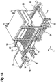
- Fig. 11 the door 12 of the housing 3 has been moved vertically to its open position, wherein, as Fig. 12 shows, the guides 21, 22 are shifted to their second limit position, thus frontally adjacent to each other and forming a continuous guide for the carriage 15 within the drying chamber 2.
- the guide unit 14 is also displaced together with the loading bridge 17 in the direction of the arrows 5, with the proviso that the loading bridge 17 and thus their guides 18 abut the end face on the guides 21 within the drying chamber 2, so that the loading bridge 17 partially into the drying chamber. 2 has been moved into it.
- a first row of drying vessels 42 passes via the conveyor belt 8 into a position in front of the carriage 15, which is thus located on the side facing away from the housing 3 of the conveyor belt 8.
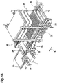
- Fig. 15 is then the carriage 15 in the rearward direction, that is moved from the on the latter footprint 19 away, and then this process is repeated after transfer of the next footprint 19 in the loading position until all shelves 19 are loaded to the initial lowest and after Retraction of the loading bridge 17 from the drying chamber 2 and closing the door 12, the method of freeze-drying can be carried out in a conventional manner.
- the carriage 15 is now driven for the purpose of pushing out the drying vessels on the loading bridge 17 on the conveyor belt 8, on which the treated by freeze drying drying vessels 42 are discharged in the direction of arrow 9.
- the carriage 15 is then retracted after emptying the bottom shelf 19 along a now empty shelf 19 again in the drying chamber 2 to its rear end position, in this case the next to be unloaded footprint 19 underfahrend.
- the latter footprint is then lowered into the unloading position and secured in this form-fitting, whereupon the unloading process is continued with the cooperation of the carriage 15 and the conveyor belt 8.
- the shelves 19 are thus unloaded successively by means of only one carriage, wherein the carriage 15 is always under loaded loading surfaces 19, so that in this respect aseptic conditions are respected.
- the freeze-drying plant has a drying chamber 2 set up in a housing 3 and an arrangement of displaceably arranged in the drying position 2 in a rack 20 for setting up drying vessels 42 containing drying surfaces.
- the housing 3 has at least one opening 13 which can be closed by a door 12.
- 2 equipped carriage 15 has. Due to the height position of the opening 13, at least one horizontal displacement plane is defined, in which the guides 16, 18, 21, 22, occupying a fixed height position, extend.
- the arrangement of the adjusting plates 19 is vertically displaceable with the proviso within the drying chamber 2, that in the displacement plane insertion of the carriage 15 by under driving loaded shelves 19, thus avoiding a direct or indirect driving over loaded shelves 19 into a rear-side limit position in the drying chamber 2 and after lowering each of the next higher loaded shelf 19 in the displacement plane a possibility of pushing out the drying vessels 42 through the opening 13 from the drying chamber 2 out by means of a second movable leading edge forming front side 23 of the carriage 15 is shown.
- the displacement plane in the drying chamber 2 and on the loading and unloading device is preferably defined by the fixed height position of the guides 16, 18, 21, 22.
- the loading and unloading device comprises a conveyor belt 8, whose conveying direction extends transversely to a direction of insertion of the drying vessels 42 in or the pushing out of the drying vessels 42 from the drying chamber 2.
- the loading and unloading device has a loading bridge 17 carrying the guides 18, which can be inserted into the drying chamber 2 for the purpose of connection to the guides 21.
- a front-side limit position of the carriage 15 is arranged on the loading and unloading device.
- the front-side limit position is located on a side of the conveyor belt 8 opposite the drying chamber 2.
- the loading and unloading device is supported on a structural unit 6, which is arranged in a direction away from the drying chamber 2 or in the direction of this movable.
- By cyclically lifting, namely transferring the next shelves 19 in the displacement plane of the loading process following shelves 19 is continued until completion of the loading of the drying chamber 2.
- the carriage 15 is retracted in the displacement plane by moving under loading loaded shelves 19 to its rear limit position in the drying chamber 2 after completion of the drying process.
- the respectively undershot footprint 19 is lowered into the displacement plane.
- the standing on the located in the displacement plane footprint 19 drying vessels 42 are by means of the front side 23 of the carriage 15 on the Opening 13 is ejected.
- the process of inserting the carriage 15 in the displacement plane in the drying chamber 2 by respectively driving under a loaded, located above the sliding plane shelf 19 to the rear limit position, lowering the loaded shelf 19 in the sliding plane and pushing out the drying vessels 42 on the Opening 13 cyclically until the completion of the unloading operation of the drying chamber 2 is then repeated.
- a displacement plane which may be an empty shelf, the pressure plate of the arrangement of shelves or the space below the pressure plate.
- the floor space to be unloaded is initially undercut and then lowered into the displacement plane, whereupon the unloading process follows.
- the guides intended to support the carriage are arranged in a fixed height position and define the position of the displacement plane.
- a conveyor belt forms part of the loading and unloading device, the conveying direction of which extends transversely to the entry or extension direction.
- a conveyor belt and a trolley may be used, the size of which depends on the footprint and in addition to the said guides also has a specific for the carriage parking position.
- Such a trolley has no conveyor belt.
- the loading and unloading device comprises, for a further embodiment, a loading bridge whose guides interact during storage of the carriage with the guides within the drying chamber.
- the carriage preferably has a second limit position located outside the drying chamber. This position can be used as parking position during the drying process. It is set up starting from the drying chamber beyond the conveyor belt if it is also to be used for loading at the same time. In other cases, it can also be set up on the dock leveler.
- a drive of the carriage is possible.
- an electric drive is used, which may also be a linear drive.
- a preferably inductive charging station may be arranged in the second limit position.
- Further embodiments relate to the drive including the guides associated therewith.
- a traction with the guides is thereafter preferably mediated via a toothed belt, which surrounds a plurality of wheels and in this way is also suitable for driving over gaps in segments of the guides.
- the drive has a flat-building, all components including a control receiving housing whose height corresponds to that of the guides.
- the housing of the carriage is preferably designed as a hermetically sealed, in particular watertight unit, which is accessible within the drying chamber a CIP cleaning process (clean in place).
- Both carriages can have a parking position on the loading and unloading device and it can be spent in the sliding plane always one of the two carriages in a sliding position and the other in a suitable position for performing a counter holding function.
- An advantage may be the exercise of a counter holding function in drying vessels with a low resistance to riot.
- a further embodiment relates to the guides intended for receiving the carriage. These are segmented in the longitudinal direction and displaceable relative to each other. They can simultaneously be designed as lateral guide edges for the drying vessels, so that in conjunction with an additional displaceable arrangement perpendicular to their longitudinal extension a simple adaptation to different dimensions of the drying vessels is possible, thus mediating a safe Aufstandposition this in the transverse direction to a pushing in or pushing out and at the same time preventing jamming and wedging, thus producing less rejects at the drying vessels.
- the guides depending on the shape of the drying vessels, eg. As in a shell drying, a gap remain that corresponds to the space required for the suspension of the shelves.
- the guides must therefore not necessarily be moved to a frontal investment position. Also, as previously stated, the carriage is to some extent suitable for traversing spaces between segments of the guides.
- vacuum-tight encapsulated gear units are provided, which are arranged outside the drying chamber arranged drive units.
- the displacement movement of said segments can also be represented structurally in a different manner, for example linked to the drive of the carriage.
- an intermediate space between two segments can be bridged by moving telescopically extendable intermediate elements in these intermediate spaces.
- This assembly may be provided for Auflagerung the loading and unloading unit particular unit, which is arranged in the direction of the drying chamber and away from this, thus movable parallel to the direction of a pushing in or out.
- This embodiment can be used particularly advantageously for maintenance purposes.
- This assembly may be arranged displaceably on rails, for example.
- the freeze dryer has been described above in connection with a drying chamber that is loaded and unloaded through only one orifice.
- the subject invention can also be used in such a system, which is designed for a passthrough operation and is therefore provided with two opposing openings, each associated with a loading and unloading.
- the further embodiment of the freeze-drying plant is directed to the known representation of a system of requirements for the located in the displacement plane footprint. This allows independent height positioning of the displacement plane in the drying chamber and is exemplified by an arrangement of bolts, which is fulfilled between an active position in which a support function is fulfilled, and an inactive position in which no support function, relative to the footprint in the displacement plane are movable.
Landscapes
- Engineering & Computer Science (AREA)
- Mechanical Engineering (AREA)
- General Engineering & Computer Science (AREA)
- Health & Medical Sciences (AREA)
- Life Sciences & Earth Sciences (AREA)
- Molecular Biology (AREA)
- Drying Of Solid Materials (AREA)
Applications Claiming Priority (3)
| Application Number | Priority Date | Filing Date | Title |
|---|---|---|---|
| DE102011117628.8A DE102011117628B4 (de) | 2011-11-04 | 2011-11-04 | Gefriertrockungsanlage mit einer Be- und Entladevorrichtung |
| EP12786840.4A EP2773913B1 (fr) | 2011-11-04 | 2012-11-03 | Installation de lyophilisation équipée d'un dispositif de chargement et déchargement |
| PCT/EP2012/004595 WO2013064266A1 (fr) | 2011-11-04 | 2012-11-03 | Installation de lyophilisation équipée d'un dispositif de chargement et déchargement |
Related Parent Applications (2)
| Application Number | Title | Priority Date | Filing Date |
|---|---|---|---|
| EP12786840.4A Division EP2773913B1 (fr) | 2011-11-04 | 2012-11-03 | Installation de lyophilisation équipée d'un dispositif de chargement et déchargement |
| EP12786840.4A Division-Into EP2773913B1 (fr) | 2011-11-04 | 2012-11-03 | Installation de lyophilisation équipée d'un dispositif de chargement et déchargement |
Publications (3)
| Publication Number | Publication Date |
|---|---|
| EP3144618A1 true EP3144618A1 (fr) | 2017-03-22 |
| EP3144618B1 EP3144618B1 (fr) | 2017-06-21 |
| EP3144618B2 EP3144618B2 (fr) | 2020-04-01 |
Family
ID=47178567
Family Applications (2)
| Application Number | Title | Priority Date | Filing Date |
|---|---|---|---|
| EP16191639.0A Active EP3144618B2 (fr) | 2011-11-04 | 2012-11-03 | Lyophilisateur |
| EP12786840.4A Active EP2773913B1 (fr) | 2011-11-04 | 2012-11-03 | Installation de lyophilisation équipée d'un dispositif de chargement et déchargement |
Family Applications After (1)
| Application Number | Title | Priority Date | Filing Date |
|---|---|---|---|
| EP12786840.4A Active EP2773913B1 (fr) | 2011-11-04 | 2012-11-03 | Installation de lyophilisation équipée d'un dispositif de chargement et déchargement |
Country Status (6)
| Country | Link |
|---|---|
| US (2) | US11236942B2 (fr) |
| EP (2) | EP3144618B2 (fr) |
| CN (1) | CN103857969B (fr) |
| DE (2) | DE102011117628B4 (fr) |
| ES (2) | ES2638237T5 (fr) |
| WO (1) | WO2013064266A1 (fr) |
Families Citing this family (22)
| Publication number | Priority date | Publication date | Assignee | Title |
|---|---|---|---|---|
| NL2003338C2 (en) * | 2009-08-07 | 2011-02-08 | Ima Life Srl | Method and assembly for handling containers in a freeze dryer. |
| CN104302996B (zh) * | 2012-03-14 | 2017-05-17 | I·M·A·工业机械自动装置股份公司 | 用于移动容器的装置 |
| ITMI20121275A1 (it) * | 2012-07-23 | 2014-01-24 | I M A Ind Macchine Automatic He S P A | Apparato di movimentazione di piani di carico per macchine liofilizzatrici |
| ITMI20130841A1 (it) * | 2013-05-23 | 2014-11-24 | I M A Ind Macchine Automatic He S P A | Dispositivo introduttore di flaconi |
| JP6173495B2 (ja) | 2013-05-29 | 2017-08-02 | ゲア・プロセス・エンジニアリング・アクティーゼルスカブ | トロリに収容されたトレイ内の製品の直列滅菌凍結乾燥を実現する方法、方法を実施するためのシステム、および方法の使用 |
| ITMI20131447A1 (it) * | 2013-09-04 | 2015-03-05 | I M A Ind Macchine Automatic He S P A | Macchina liofilizzatrice comprendente almeno un organo di guida per dispositivi di carico |
| ITUA20161823A1 (it) * | 2016-03-18 | 2017-09-18 | I M A Industria Macch Automatiche S P A In Sigla Ima S P A | Apparato per caricare e scaricare un liofilizzatore. |
| US11268759B2 (en) * | 2017-03-24 | 2022-03-08 | Azbil Corporation | Housing device |
| JP7110360B2 (ja) | 2017-10-09 | 2022-08-01 | テルモ ビーシーティー バイオテクノロジーズ,エルエルシー | 凍結乾燥方法 |
| EP3473959B1 (fr) | 2017-10-20 | 2020-02-12 | Martin Christ Gefriertrocknungsanlagen GmbH | Procédé de détermination basé sur la pression d'un paramètre de produit dans un congélateur, congélateur et produit logiciel |
| ES2787019T3 (es) | 2017-12-15 | 2020-10-14 | Martin Christ Gefriertrocknungsanlagen Gmbh | Liofilizador, instalación de liofilización, procedimiento de funcionamiento un liofilizador y nuevo uso de un carro |
| CN113597532B (zh) * | 2019-03-14 | 2023-02-17 | 泰尔茂比司特生物技术有限公司 | 冻干容器填充固定装置、系统及使用方法 |
| CN110159721A (zh) * | 2019-06-04 | 2019-08-23 | 深圳市时代高科技设备股份有限公司 | 传动机构及粉体干燥加热炉 |
| CN110220370B (zh) * | 2019-06-26 | 2023-11-17 | 东莞市德瑞精密设备有限公司 | 货架式锂电池烘烤设备 |
| CN111219978B (zh) * | 2020-03-18 | 2024-09-03 | 无锡先导智能装备股份有限公司 | 中转装置及烘干设备 |
| CN113803984B (zh) * | 2021-08-16 | 2023-02-17 | 上海奥星制药技术装备有限公司 | 一种原料药自动进出料装置 |
| CN114294929B (zh) * | 2022-01-14 | 2023-03-10 | 深圳市信亿德科技有限公司 | 一种具有升降机构的快速均匀烘烤的工业用烤箱 |
| DE102022103429B3 (de) | 2022-02-14 | 2023-05-04 | Martin Christ Gefriertrocknungsanlagen Gmbh | Be- und Entladeeinrichtung für einen Gefriertrockner, Verfahren und Gefriertrocknungsanlage |
| CN116812474A (zh) * | 2023-07-06 | 2023-09-29 | 浙江同景冻干科技有限公司 | 一种冻干自动输送系统 |
| CN117589670B (zh) * | 2024-01-18 | 2024-04-09 | 江苏永成汽车零部件股份有限公司 | 用于汽车门饰板的喷漆表面质量检测系统 |
| CN118776262B (zh) * | 2024-09-12 | 2024-11-19 | 赣州职业技术学院 | 一种宠物饲料自动冻干设备 |
| CN119845009B (zh) * | 2025-03-24 | 2025-05-27 | 山西晋享印刷包装有限公司 | 一种纸浆模塑烘干加热装置 |
Citations (6)
| Publication number | Priority date | Publication date | Assignee | Title |
|---|---|---|---|---|
| DE10307571A1 (de) | 2003-02-22 | 2004-09-02 | Steris Gmbh | Einrichtung mit einer Stellfläche |
| WO2005121671A1 (fr) | 2004-06-11 | 2005-12-22 | The Boc Group Plc | Lyophilisateur |
| DE602004003692T2 (de) | 2004-07-22 | 2007-10-04 | Ima-Telstar S.L. | Vorrichtung zum Laden und Entladen von Behältern |
| DE202008012379U1 (de) * | 2008-09-18 | 2008-12-24 | Gea Lyophil Gmbh | Transfervorrichtung für eine Gefriertrocknungsanlage |
| FR2918653A1 (fr) * | 2007-07-13 | 2009-01-16 | Usifroid Sa Sa | Dispositif de dechargement d'une armoire de traitement de produits |
| WO2011045008A1 (fr) * | 2009-10-12 | 2011-04-21 | Martin Christ Gefriertrocknungsanlagen Gmbh | Dispositif de chargement et de déchargement pour une installation de lyophilisation |
Family Cites Families (12)
| Publication number | Priority date | Publication date | Assignee | Title |
|---|---|---|---|---|
| US4781067A (en) * | 1987-04-30 | 1988-11-01 | Sonoscan, Inc. | Balanced scanning mechanism |
| DE9001612U1 (de) * | 1989-04-07 | 1990-04-19 | Finn-Aqua Santasalo-Sohlberg GmbH, 50354 Hürth | Vorrichtung zum Beschicken und Entladen einer Gefriertrocknungseinrichtung |
| US5014583A (en) * | 1989-08-29 | 1991-05-14 | Webb William J | Push feed system for a saw |
| US6331744B1 (en) | 1998-02-10 | 2001-12-18 | Light Sciences Corporation | Contactless energy transfer apparatus |
| US7051660B2 (en) | 2003-04-04 | 2006-05-30 | Metso Minerals Industries, Inc. | Carriage assembly for positioning railroad cars |
| EA008205B1 (ru) | 2003-08-25 | 2007-04-27 | Джеффри А. Спрей | Расширяемые трубные изделия для использования в геологических структурах, способы расширения трубных изделий и способы их изготовления |
| GB0413115D0 (en) | 2004-06-11 | 2004-07-14 | Boc Group Plc | Freeze dryer |
| JP2006226633A (ja) * | 2005-02-18 | 2006-08-31 | Kyowa Shinku Gijutsu Kk | 凍結乾燥機における小容器のローディング方法とローディング装置 |
| ES2422210T3 (es) * | 2006-07-18 | 2013-09-09 | Telstar Technologies S L U | Aparato para mover recipientes |
| DE102007034197B4 (de) * | 2007-07-23 | 2013-06-06 | Accurro Gmbh | Vorrichtung zum Be- und Entladen einer Stellplatte einer Gefriertrocknungsanlage und ein Verfahren hierfür |
| DE102008046538B4 (de) | 2008-09-10 | 2014-08-07 | Sommer Antriebs- Und Funktechnik Gmbh | Antriebssystem für ein Tor |
| NL2003338C2 (en) | 2009-08-07 | 2011-02-08 | Ima Life Srl | Method and assembly for handling containers in a freeze dryer. |
-
2011
- 2011-11-04 DE DE102011117628.8A patent/DE102011117628B4/de not_active Expired - Fee Related
-
2012
- 2012-11-03 EP EP16191639.0A patent/EP3144618B2/fr active Active
- 2012-11-03 DE DE202012013409.4U patent/DE202012013409U1/de not_active Expired - Lifetime
- 2012-11-03 ES ES16191639T patent/ES2638237T5/es active Active
- 2012-11-03 US US14/345,913 patent/US11236942B2/en active Active
- 2012-11-03 EP EP12786840.4A patent/EP2773913B1/fr active Active
- 2012-11-03 CN CN201280046823.7A patent/CN103857969B/zh active Active
- 2012-11-03 ES ES12786840.4T patent/ES2624146T3/es active Active
- 2012-11-03 WO PCT/EP2012/004595 patent/WO2013064266A1/fr not_active Ceased
-
2016
- 2016-10-21 US US15/299,803 patent/US11236943B2/en active Active
Patent Citations (6)
| Publication number | Priority date | Publication date | Assignee | Title |
|---|---|---|---|---|
| DE10307571A1 (de) | 2003-02-22 | 2004-09-02 | Steris Gmbh | Einrichtung mit einer Stellfläche |
| WO2005121671A1 (fr) | 2004-06-11 | 2005-12-22 | The Boc Group Plc | Lyophilisateur |
| DE602004003692T2 (de) | 2004-07-22 | 2007-10-04 | Ima-Telstar S.L. | Vorrichtung zum Laden und Entladen von Behältern |
| FR2918653A1 (fr) * | 2007-07-13 | 2009-01-16 | Usifroid Sa Sa | Dispositif de dechargement d'une armoire de traitement de produits |
| DE202008012379U1 (de) * | 2008-09-18 | 2008-12-24 | Gea Lyophil Gmbh | Transfervorrichtung für eine Gefriertrocknungsanlage |
| WO2011045008A1 (fr) * | 2009-10-12 | 2011-04-21 | Martin Christ Gefriertrocknungsanlagen Gmbh | Dispositif de chargement et de déchargement pour une installation de lyophilisation |
Also Published As
| Publication number | Publication date |
|---|---|
| DE102011117628B4 (de) | 2015-10-22 |
| US11236942B2 (en) | 2022-02-01 |
| ES2638237T5 (es) | 2021-01-18 |
| EP3144618B1 (fr) | 2017-06-21 |
| CN103857969B (zh) | 2016-03-09 |
| EP2773913B1 (fr) | 2017-03-01 |
| EP3144618B2 (fr) | 2020-04-01 |
| DE202012013409U1 (de) | 2016-11-09 |
| ES2638237T3 (es) | 2017-10-19 |
| EP2773913A1 (fr) | 2014-09-10 |
| DE102011117628A1 (de) | 2013-05-08 |
| US20170059246A1 (en) | 2017-03-02 |
| CN103857969A (zh) | 2014-06-11 |
| US11236943B2 (en) | 2022-02-01 |
| US20140230265A1 (en) | 2014-08-21 |
| ES2624146T3 (es) | 2017-07-13 |
| WO2013064266A1 (fr) | 2013-05-10 |
Similar Documents
| Publication | Publication Date | Title |
|---|---|---|
| EP3144618B1 (fr) | Chariot pour lyophilisateurs et lyophilisateur | |
| DE3320848C2 (fr) | ||
| EP2613995B2 (fr) | Installation de traitement de surface de carrosseries de véhicules | |
| EP2488808B1 (fr) | Dispositif de chargement et de déchargement pour une installation de lyophilisation | |
| EP2085490B1 (fr) | Dispositif pour le recuit d'objets | |
| DE102010047744A1 (de) | Be- und Entladevorrichtung für eine Gefriertrocknungsanlage | |
| EP0359014A2 (fr) | Dispositif d'évacuation de pièces injectées d'une machine à mouler des matières plastiques par injection | |
| EP3499160B1 (fr) | Lyophilisateur, installation de lyophilisateur, procédé de fonctionnement d'un lyophilisateur et nouvelle utilisation d'un chariot | |
| DE3208019A1 (de) | Automatische wiegevorrichtung fuer fruechte od.dgl. | |
| EP0246398A2 (fr) | Dispositif de changement de moule pour un groupe de machine à injecter les matières plastiques | |
| DE10318082A1 (de) | Einheit zur Montage von Bauteilen auf Paneelen aus Holz oder ähnlichen Werkstoffen | |
| EP1837295B1 (fr) | Dispositif doté d'aires de stockage, en particulier pour la réception de portes-pièces, tout comme système doté d'une bande convoyeuse et d'un dispositif destiné à la réception de portes-pièces | |
| DE2441095A1 (de) | Werkstueckspeicher fuer werkzeugmaschinen, insbesondere verzahnmaschinen | |
| DE102005046821A1 (de) | Horizontal-Umlauflagersystem | |
| CH665378A5 (de) | Vorrichtung zum exakten positionieren eines werkstuecks. | |
| DE2409725C3 (de) | Gefrieranlage | |
| CH370563A (de) | Einrichtung zum Lagern von Gegenständen | |
| EP4059850A1 (fr) | Dispositif de remplissage pour un réservoir de tubes d'une machine d'emballage et procédé de remplissage d'un réservoir de tubes | |
| AT339028B (de) | Heb- und senkbare formlingsbeschickungs- und pressunterlagen-entleerungsvorrichtung fur eine mehretagenpresse | |
| EP0890880B1 (fr) | Appareil pour le traitement de plaques d'impression | |
| DE1558017B1 (de) | Chargierwagen | |
| DE3013014A1 (de) | Einrichtung zur herstellung und verpackung von zigaretten | |
| DE2222599C3 (de) | Vorrichtung zum selbsttätigen Beladen eines Hordenwagens | |
| DE2220846A1 (de) | Verfahren und vorrichtung zum zerlegen von ziegelstapeln | |
| DE2245280A1 (de) | Turm-trocknungsvorrichtung fuer plattenmaterial |
Legal Events
| Date | Code | Title | Description |
|---|---|---|---|
| PUAI | Public reference made under article 153(3) epc to a published international application that has entered the european phase |
Free format text: ORIGINAL CODE: 0009012 |
|
| STAA | Information on the status of an ep patent application or granted ep patent |
Free format text: STATUS: THE APPLICATION HAS BEEN PUBLISHED |
|
| STAA | Information on the status of an ep patent application or granted ep patent |
Free format text: STATUS: REQUEST FOR EXAMINATION WAS MADE |
|
| AC | Divisional application: reference to earlier application |
Ref document number: 2773913 Country of ref document: EP Kind code of ref document: P |
|
| AK | Designated contracting states |
Kind code of ref document: A1 Designated state(s): AL AT BE BG CH CY CZ DE DK EE ES FI FR GB GR HR HU IE IS IT LI LT LU LV MC MK MT NL NO PL PT RO RS SE SI SK SM TR |
|
| 17P | Request for examination filed |
Effective date: 20170224 |
|
| RBV | Designated contracting states (corrected) |
Designated state(s): AL AT BE BG CH CY CZ DE DK EE ES FI FR GB GR HR HU IE IS IT LI LT LU LV MC MK MT NL NO PL PT RO RS SE SI SK SM TR |
|
| GRAP | Despatch of communication of intention to grant a patent |
Free format text: ORIGINAL CODE: EPIDOSNIGR1 |
|
| STAA | Information on the status of an ep patent application or granted ep patent |
Free format text: STATUS: GRANT OF PATENT IS INTENDED |
|
| INTG | Intention to grant announced |
Effective date: 20170420 |
|
| RIN1 | Information on inventor provided before grant (corrected) |
Inventor name: CHRIST, MARTIN |
|
| GRAS | Grant fee paid |
Free format text: ORIGINAL CODE: EPIDOSNIGR3 |
|
| GRAA | (expected) grant |
Free format text: ORIGINAL CODE: 0009210 |
|
| STAA | Information on the status of an ep patent application or granted ep patent |
Free format text: STATUS: THE PATENT HAS BEEN GRANTED |
|
| AC | Divisional application: reference to earlier application |
Ref document number: 2773913 Country of ref document: EP Kind code of ref document: P |
|
| AK | Designated contracting states |
Kind code of ref document: B1 Designated state(s): AL AT BE BG CH CY CZ DE DK EE ES FI FR GB GR HR HU IE IS IT LI LT LU LV MC MK MT NL NO PL PT RO RS SE SI SK SM TR |
|
| REG | Reference to a national code |
Ref country code: GB Ref legal event code: FG4D Free format text: NOT ENGLISH |
|
| REG | Reference to a national code |
Ref country code: CH Ref legal event code: EP |
|
| REG | Reference to a national code |
Ref country code: IE Ref legal event code: FG4D Free format text: LANGUAGE OF EP DOCUMENT: GERMAN |
|
| REG | Reference to a national code |
Ref country code: AT Ref legal event code: REF Ref document number: 903342 Country of ref document: AT Kind code of ref document: T Effective date: 20170715 |
|
| REG | Reference to a national code |
Ref country code: DE Ref legal event code: R096 Ref document number: 502012010622 Country of ref document: DE |
|
| REG | Reference to a national code |
Ref country code: NL Ref legal event code: FP |
|
| REG | Reference to a national code |
Ref country code: ES Ref legal event code: FG2A Ref document number: 2638237 Country of ref document: ES Kind code of ref document: T3 Effective date: 20171019 |
|
| PG25 | Lapsed in a contracting state [announced via postgrant information from national office to epo] |
Ref country code: HR Free format text: LAPSE BECAUSE OF FAILURE TO SUBMIT A TRANSLATION OF THE DESCRIPTION OR TO PAY THE FEE WITHIN THE PRESCRIBED TIME-LIMIT Effective date: 20170621 Ref country code: LT Free format text: LAPSE BECAUSE OF FAILURE TO SUBMIT A TRANSLATION OF THE DESCRIPTION OR TO PAY THE FEE WITHIN THE PRESCRIBED TIME-LIMIT Effective date: 20170621 Ref country code: GR Free format text: LAPSE BECAUSE OF FAILURE TO SUBMIT A TRANSLATION OF THE DESCRIPTION OR TO PAY THE FEE WITHIN THE PRESCRIBED TIME-LIMIT Effective date: 20170922 Ref country code: NO Free format text: LAPSE BECAUSE OF FAILURE TO SUBMIT A TRANSLATION OF THE DESCRIPTION OR TO PAY THE FEE WITHIN THE PRESCRIBED TIME-LIMIT Effective date: 20170921 Ref country code: FI Free format text: LAPSE BECAUSE OF FAILURE TO SUBMIT A TRANSLATION OF THE DESCRIPTION OR TO PAY THE FEE WITHIN THE PRESCRIBED TIME-LIMIT Effective date: 20170621 |
|
| REG | Reference to a national code |
Ref country code: LT Ref legal event code: MG4D |
|
| REG | Reference to a national code |
Ref country code: FR Ref legal event code: PLFP Year of fee payment: 6 |
|
| PG25 | Lapsed in a contracting state [announced via postgrant information from national office to epo] |
Ref country code: LV Free format text: LAPSE BECAUSE OF FAILURE TO SUBMIT A TRANSLATION OF THE DESCRIPTION OR TO PAY THE FEE WITHIN THE PRESCRIBED TIME-LIMIT Effective date: 20170621 Ref country code: RS Free format text: LAPSE BECAUSE OF FAILURE TO SUBMIT A TRANSLATION OF THE DESCRIPTION OR TO PAY THE FEE WITHIN THE PRESCRIBED TIME-LIMIT Effective date: 20170621 Ref country code: SE Free format text: LAPSE BECAUSE OF FAILURE TO SUBMIT A TRANSLATION OF THE DESCRIPTION OR TO PAY THE FEE WITHIN THE PRESCRIBED TIME-LIMIT Effective date: 20170621 Ref country code: BG Free format text: LAPSE BECAUSE OF FAILURE TO SUBMIT A TRANSLATION OF THE DESCRIPTION OR TO PAY THE FEE WITHIN THE PRESCRIBED TIME-LIMIT Effective date: 20170921 |
|
| PG25 | Lapsed in a contracting state [announced via postgrant information from national office to epo] |
Ref country code: EE Free format text: LAPSE BECAUSE OF FAILURE TO SUBMIT A TRANSLATION OF THE DESCRIPTION OR TO PAY THE FEE WITHIN THE PRESCRIBED TIME-LIMIT Effective date: 20170621 Ref country code: SK Free format text: LAPSE BECAUSE OF FAILURE TO SUBMIT A TRANSLATION OF THE DESCRIPTION OR TO PAY THE FEE WITHIN THE PRESCRIBED TIME-LIMIT Effective date: 20170621 Ref country code: CZ Free format text: LAPSE BECAUSE OF FAILURE TO SUBMIT A TRANSLATION OF THE DESCRIPTION OR TO PAY THE FEE WITHIN THE PRESCRIBED TIME-LIMIT Effective date: 20170621 |
|
| PG25 | Lapsed in a contracting state [announced via postgrant information from national office to epo] |
Ref country code: IS Free format text: LAPSE BECAUSE OF FAILURE TO SUBMIT A TRANSLATION OF THE DESCRIPTION OR TO PAY THE FEE WITHIN THE PRESCRIBED TIME-LIMIT Effective date: 20171021 Ref country code: SM Free format text: LAPSE BECAUSE OF FAILURE TO SUBMIT A TRANSLATION OF THE DESCRIPTION OR TO PAY THE FEE WITHIN THE PRESCRIBED TIME-LIMIT Effective date: 20170621 Ref country code: PL Free format text: LAPSE BECAUSE OF FAILURE TO SUBMIT A TRANSLATION OF THE DESCRIPTION OR TO PAY THE FEE WITHIN THE PRESCRIBED TIME-LIMIT Effective date: 20170621 |
|
| REG | Reference to a national code |
Ref country code: DE Ref legal event code: R026 Ref document number: 502012010622 Country of ref document: DE |
|
| PLBI | Opposition filed |
Free format text: ORIGINAL CODE: 0009260 |
|
| PLAX | Notice of opposition and request to file observation + time limit sent |
Free format text: ORIGINAL CODE: EPIDOSNOBS2 |
|
| 26 | Opposition filed |
Opponent name: MOLNIA, DAVID Effective date: 20180320 Opponent name: I.M.A. INDUSTRIA MACCHINE AUTOMATICHE SPA Effective date: 20180321 |
|
| PG25 | Lapsed in a contracting state [announced via postgrant information from national office to epo] |
Ref country code: DK Free format text: LAPSE BECAUSE OF FAILURE TO SUBMIT A TRANSLATION OF THE DESCRIPTION OR TO PAY THE FEE WITHIN THE PRESCRIBED TIME-LIMIT Effective date: 20170621 |
|
| PG25 | Lapsed in a contracting state [announced via postgrant information from national office to epo] |
Ref country code: MC Free format text: LAPSE BECAUSE OF FAILURE TO SUBMIT A TRANSLATION OF THE DESCRIPTION OR TO PAY THE FEE WITHIN THE PRESCRIBED TIME-LIMIT Effective date: 20170621 |
|
| PG25 | Lapsed in a contracting state [announced via postgrant information from national office to epo] |
Ref country code: CH Free format text: LAPSE BECAUSE OF NON-PAYMENT OF DUE FEES Effective date: 20171130 Ref country code: LI Free format text: LAPSE BECAUSE OF NON-PAYMENT OF DUE FEES Effective date: 20171130 |
|
| PG25 | Lapsed in a contracting state [announced via postgrant information from national office to epo] |
Ref country code: SI Free format text: LAPSE BECAUSE OF FAILURE TO SUBMIT A TRANSLATION OF THE DESCRIPTION OR TO PAY THE FEE WITHIN THE PRESCRIBED TIME-LIMIT Effective date: 20170621 Ref country code: LU Free format text: LAPSE BECAUSE OF NON-PAYMENT OF DUE FEES Effective date: 20171103 |
|
| REG | Reference to a national code |
Ref country code: BE Ref legal event code: MM Effective date: 20171130 |
|
| REG | Reference to a national code |
Ref country code: IE Ref legal event code: MM4A |
|
| PLBB | Reply of patent proprietor to notice(s) of opposition received |
Free format text: ORIGINAL CODE: EPIDOSNOBS3 |
|
| PG25 | Lapsed in a contracting state [announced via postgrant information from national office to epo] |
Ref country code: MT Free format text: LAPSE BECAUSE OF FAILURE TO SUBMIT A TRANSLATION OF THE DESCRIPTION OR TO PAY THE FEE WITHIN THE PRESCRIBED TIME-LIMIT Effective date: 20170621 |
|
| PG25 | Lapsed in a contracting state [announced via postgrant information from national office to epo] |
Ref country code: IE Free format text: LAPSE BECAUSE OF NON-PAYMENT OF DUE FEES Effective date: 20171103 |
|
| PG25 | Lapsed in a contracting state [announced via postgrant information from national office to epo] |
Ref country code: BE Free format text: LAPSE BECAUSE OF NON-PAYMENT OF DUE FEES Effective date: 20171130 |
|
| REG | Reference to a national code |
Ref country code: AT Ref legal event code: MM01 Ref document number: 903342 Country of ref document: AT Kind code of ref document: T Effective date: 20171103 |
|
| PLBP | Opposition withdrawn |
Free format text: ORIGINAL CODE: 0009264 |
|
| PG25 | Lapsed in a contracting state [announced via postgrant information from national office to epo] |
Ref country code: AT Free format text: LAPSE BECAUSE OF NON-PAYMENT OF DUE FEES Effective date: 20171103 |
|
| PG25 | Lapsed in a contracting state [announced via postgrant information from national office to epo] |
Ref country code: HU Free format text: LAPSE BECAUSE OF FAILURE TO SUBMIT A TRANSLATION OF THE DESCRIPTION OR TO PAY THE FEE WITHIN THE PRESCRIBED TIME-LIMIT; INVALID AB INITIO Effective date: 20121103 |
|
| PG25 | Lapsed in a contracting state [announced via postgrant information from national office to epo] |
Ref country code: RO Free format text: LAPSE BECAUSE OF FAILURE TO SUBMIT A TRANSLATION OF THE DESCRIPTION OR TO PAY THE FEE WITHIN THE PRESCRIBED TIME-LIMIT Effective date: 20170621 |
|
| PG25 | Lapsed in a contracting state [announced via postgrant information from national office to epo] |
Ref country code: CY Free format text: LAPSE BECAUSE OF FAILURE TO SUBMIT A TRANSLATION OF THE DESCRIPTION OR TO PAY THE FEE WITHIN THE PRESCRIBED TIME-LIMIT Effective date: 20170621 |
|
| PG25 | Lapsed in a contracting state [announced via postgrant information from national office to epo] |
Ref country code: MK Free format text: LAPSE BECAUSE OF FAILURE TO SUBMIT A TRANSLATION OF THE DESCRIPTION OR TO PAY THE FEE WITHIN THE PRESCRIBED TIME-LIMIT Effective date: 20170621 |
|
| PUAH | Patent maintained in amended form |
Free format text: ORIGINAL CODE: 0009272 |
|
| STAA | Information on the status of an ep patent application or granted ep patent |
Free format text: STATUS: PATENT MAINTAINED AS AMENDED |
|
| PG25 | Lapsed in a contracting state [announced via postgrant information from national office to epo] |
Ref country code: TR Free format text: LAPSE BECAUSE OF FAILURE TO SUBMIT A TRANSLATION OF THE DESCRIPTION OR TO PAY THE FEE WITHIN THE PRESCRIBED TIME-LIMIT Effective date: 20170621 |
|
| 27A | Patent maintained in amended form |
Effective date: 20200401 |
|
| AK | Designated contracting states |
Kind code of ref document: B2 Designated state(s): AL AT BE BG CH CY CZ DE DK EE ES FI FR GB GR HR HU IE IS IT LI LT LU LV MC MK MT NL NO PL PT RO RS SE SI SK SM TR |
|
| REG | Reference to a national code |
Ref country code: DE Ref legal event code: R102 Ref document number: 502012010622 Country of ref document: DE |
|
| PG25 | Lapsed in a contracting state [announced via postgrant information from national office to epo] |
Ref country code: PT Free format text: LAPSE BECAUSE OF FAILURE TO SUBMIT A TRANSLATION OF THE DESCRIPTION OR TO PAY THE FEE WITHIN THE PRESCRIBED TIME-LIMIT Effective date: 20170621 |
|
| REG | Reference to a national code |
Ref country code: NL Ref legal event code: FP |
|
| PG25 | Lapsed in a contracting state [announced via postgrant information from national office to epo] |
Ref country code: AL Free format text: LAPSE BECAUSE OF FAILURE TO SUBMIT A TRANSLATION OF THE DESCRIPTION OR TO PAY THE FEE WITHIN THE PRESCRIBED TIME-LIMIT Effective date: 20170621 |
|
| REG | Reference to a national code |
Ref country code: ES Ref legal event code: DC2A Ref document number: 2638237 Country of ref document: ES Kind code of ref document: T5 Effective date: 20210118 |
|
| P01 | Opt-out of the competence of the unified patent court (upc) registered |
Effective date: 20230529 |
|
| PGFP | Annual fee paid to national office [announced via postgrant information from national office to epo] |
Ref country code: NL Payment date: 20241120 Year of fee payment: 13 |
|
| PGFP | Annual fee paid to national office [announced via postgrant information from national office to epo] |
Ref country code: GB Payment date: 20241121 Year of fee payment: 13 |
|
| PGFP | Annual fee paid to national office [announced via postgrant information from national office to epo] |
Ref country code: FR Payment date: 20241120 Year of fee payment: 13 |
|
| PGFP | Annual fee paid to national office [announced via postgrant information from national office to epo] |
Ref country code: DE Payment date: 20250819 Year of fee payment: 14 |
|
| PGFP | Annual fee paid to national office [announced via postgrant information from national office to epo] |
Ref country code: IT Payment date: 20251128 Year of fee payment: 14 |
|
| PGFP | Annual fee paid to national office [announced via postgrant information from national office to epo] |
Ref country code: ES Payment date: 20251216 Year of fee payment: 14 |