EP3144724A1 - Dispositif de conversion de longueur d'onde, système source de lumière et système de projection - Google Patents
Dispositif de conversion de longueur d'onde, système source de lumière et système de projection Download PDFInfo
- Publication number
- EP3144724A1 EP3144724A1 EP15792223.8A EP15792223A EP3144724A1 EP 3144724 A1 EP3144724 A1 EP 3144724A1 EP 15792223 A EP15792223 A EP 15792223A EP 3144724 A1 EP3144724 A1 EP 3144724A1
- Authority
- EP
- European Patent Office
- Prior art keywords
- wavelength conversion
- thermally
- layer
- conversion device
- material layer
- Prior art date
- Legal status (The legal status is an assumption and is not a legal conclusion. Google has not performed a legal analysis and makes no representation as to the accuracy of the status listed.)
- Granted
Links
Images

Classifications
-
- F—MECHANICAL ENGINEERING; LIGHTING; HEATING; WEAPONS; BLASTING
- F21—LIGHTING
- F21V—FUNCTIONAL FEATURES OR DETAILS OF LIGHTING DEVICES OR SYSTEMS THEREOF; STRUCTURAL COMBINATIONS OF LIGHTING DEVICES WITH OTHER ARTICLES, NOT OTHERWISE PROVIDED FOR
- F21V9/00—Elements for modifying spectral properties, polarisation or intensity of the light emitted, e.g. filters
- F21V9/20—Dichroic filters, i.e. devices operating on the principle of wave interference to pass specific ranges of wavelengths while cancelling others
-
- G—PHYSICS
- G02—OPTICS
- G02F—OPTICAL DEVICES OR ARRANGEMENTS FOR THE CONTROL OF LIGHT BY MODIFICATION OF THE OPTICAL PROPERTIES OF THE MEDIA OF THE ELEMENTS INVOLVED THEREIN; NON-LINEAR OPTICS; FREQUENCY-CHANGING OF LIGHT; OPTICAL LOGIC ELEMENTS; OPTICAL ANALOGUE/DIGITAL CONVERTERS
- G02F1/00—Devices or arrangements for the control of the intensity, colour, phase, polarisation or direction of light arriving from an independent light source, e.g. switching, gating or modulating; Non-linear optics
- G02F1/35—Non-linear optics
- G02F1/353—Frequency conversion, i.e. wherein a light beam is generated with frequency components different from those of the incident light beams
-
- F—MECHANICAL ENGINEERING; LIGHTING; HEATING; WEAPONS; BLASTING
- F21—LIGHTING
- F21V—FUNCTIONAL FEATURES OR DETAILS OF LIGHTING DEVICES OR SYSTEMS THEREOF; STRUCTURAL COMBINATIONS OF LIGHTING DEVICES WITH OTHER ARTICLES, NOT OTHERWISE PROVIDED FOR
- F21V29/00—Protecting lighting devices from thermal damage; Cooling or heating arrangements specially adapted for lighting devices or systems
- F21V29/50—Cooling arrangements
- F21V29/502—Cooling arrangements characterised by the adaptation for cooling of specific components
-
- F—MECHANICAL ENGINEERING; LIGHTING; HEATING; WEAPONS; BLASTING
- F21—LIGHTING
- F21V—FUNCTIONAL FEATURES OR DETAILS OF LIGHTING DEVICES OR SYSTEMS THEREOF; STRUCTURAL COMBINATIONS OF LIGHTING DEVICES WITH OTHER ARTICLES, NOT OTHERWISE PROVIDED FOR
- F21V29/00—Protecting lighting devices from thermal damage; Cooling or heating arrangements specially adapted for lighting devices or systems
- F21V29/85—Protecting lighting devices from thermal damage; Cooling or heating arrangements specially adapted for lighting devices or systems characterised by the material
- F21V29/86—Ceramics or glass
-
- F—MECHANICAL ENGINEERING; LIGHTING; HEATING; WEAPONS; BLASTING
- F21—LIGHTING
- F21V—FUNCTIONAL FEATURES OR DETAILS OF LIGHTING DEVICES OR SYSTEMS THEREOF; STRUCTURAL COMBINATIONS OF LIGHTING DEVICES WITH OTHER ARTICLES, NOT OTHERWISE PROVIDED FOR
- F21V9/00—Elements for modifying spectral properties, polarisation or intensity of the light emitted, e.g. filters
- F21V9/08—Elements for modifying spectral properties, polarisation or intensity of the light emitted, e.g. filters for producing coloured light, e.g. monochromatic; for reducing intensity of light
-
- G—PHYSICS
- G02—OPTICS
- G02B—OPTICAL ELEMENTS, SYSTEMS OR APPARATUS
- G02B26/00—Optical devices or arrangements for the control of light using movable or deformable optical elements
- G02B26/007—Optical devices or arrangements for the control of light using movable or deformable optical elements the movable or deformable optical element controlling the colour, i.e. a spectral characteristic, of the light
-
- G—PHYSICS
- G02—OPTICS
- G02F—OPTICAL DEVICES OR ARRANGEMENTS FOR THE CONTROL OF LIGHT BY MODIFICATION OF THE OPTICAL PROPERTIES OF THE MEDIA OF THE ELEMENTS INVOLVED THEREIN; NON-LINEAR OPTICS; FREQUENCY-CHANGING OF LIGHT; OPTICAL LOGIC ELEMENTS; OPTICAL ANALOGUE/DIGITAL CONVERTERS
- G02F1/00—Devices or arrangements for the control of the intensity, colour, phase, polarisation or direction of light arriving from an independent light source, e.g. switching, gating or modulating; Non-linear optics
- G02F1/35—Non-linear optics
-
- G—PHYSICS
- G03—PHOTOGRAPHY; CINEMATOGRAPHY; ANALOGOUS TECHNIQUES USING WAVES OTHER THAN OPTICAL WAVES; ELECTROGRAPHY; HOLOGRAPHY
- G03B—APPARATUS OR ARRANGEMENTS FOR TAKING PHOTOGRAPHS OR FOR PROJECTING OR VIEWING THEM; APPARATUS OR ARRANGEMENTS EMPLOYING ANALOGOUS TECHNIQUES USING WAVES OTHER THAN OPTICAL WAVES; ACCESSORIES THEREFOR
- G03B21/00—Projectors or projection-type viewers; Accessories therefor
- G03B21/14—Details
-
- G—PHYSICS
- G03—PHOTOGRAPHY; CINEMATOGRAPHY; ANALOGOUS TECHNIQUES USING WAVES OTHER THAN OPTICAL WAVES; ELECTROGRAPHY; HOLOGRAPHY
- G03B—APPARATUS OR ARRANGEMENTS FOR TAKING PHOTOGRAPHS OR FOR PROJECTING OR VIEWING THEM; APPARATUS OR ARRANGEMENTS EMPLOYING ANALOGOUS TECHNIQUES USING WAVES OTHER THAN OPTICAL WAVES; ACCESSORIES THEREFOR
- G03B21/00—Projectors or projection-type viewers; Accessories therefor
- G03B21/14—Details
- G03B21/16—Cooling; Preventing overheating
-
- G—PHYSICS
- G03—PHOTOGRAPHY; CINEMATOGRAPHY; ANALOGOUS TECHNIQUES USING WAVES OTHER THAN OPTICAL WAVES; ELECTROGRAPHY; HOLOGRAPHY
- G03B—APPARATUS OR ARRANGEMENTS FOR TAKING PHOTOGRAPHS OR FOR PROJECTING OR VIEWING THEM; APPARATUS OR ARRANGEMENTS EMPLOYING ANALOGOUS TECHNIQUES USING WAVES OTHER THAN OPTICAL WAVES; ACCESSORIES THEREFOR
- G03B21/00—Projectors or projection-type viewers; Accessories therefor
- G03B21/14—Details
- G03B21/20—Lamp housings
- G03B21/2006—Lamp housings characterised by the light source
-
- G—PHYSICS
- G03—PHOTOGRAPHY; CINEMATOGRAPHY; ANALOGOUS TECHNIQUES USING WAVES OTHER THAN OPTICAL WAVES; ELECTROGRAPHY; HOLOGRAPHY
- G03B—APPARATUS OR ARRANGEMENTS FOR TAKING PHOTOGRAPHS OR FOR PROJECTING OR VIEWING THEM; APPARATUS OR ARRANGEMENTS EMPLOYING ANALOGOUS TECHNIQUES USING WAVES OTHER THAN OPTICAL WAVES; ACCESSORIES THEREFOR
- G03B21/00—Projectors or projection-type viewers; Accessories therefor
- G03B21/14—Details
- G03B21/20—Lamp housings
- G03B21/2006—Lamp housings characterised by the light source
- G03B21/2033—LED or laser light sources
- G03B21/204—LED or laser light sources using secondary light emission, e.g. luminescence or fluorescence
-
- H—ELECTRICITY
- H10—SEMICONDUCTOR DEVICES; ELECTRIC SOLID-STATE DEVICES NOT OTHERWISE PROVIDED FOR
- H10H—INORGANIC LIGHT-EMITTING SEMICONDUCTOR DEVICES HAVING POTENTIAL BARRIERS
- H10H20/00—Individual inorganic light-emitting semiconductor devices having potential barriers, e.g. light-emitting diodes [LED]
- H10H20/80—Constructional details
- H10H20/85—Packages
- H10H20/851—Wavelength conversion means
- H10H20/8515—Wavelength conversion means not being in contact with the bodies
-
- H—ELECTRICITY
- H10—SEMICONDUCTOR DEVICES; ELECTRIC SOLID-STATE DEVICES NOT OTHERWISE PROVIDED FOR
- H10H—INORGANIC LIGHT-EMITTING SEMICONDUCTOR DEVICES HAVING POTENTIAL BARRIERS
- H10H20/00—Individual inorganic light-emitting semiconductor devices having potential barriers, e.g. light-emitting diodes [LED]
- H10H20/80—Constructional details
- H10H20/85—Packages
- H10H20/858—Means for heat extraction or cooling
- H10H20/8583—Means for heat extraction or cooling not being in contact with the bodies
-
- H—ELECTRICITY
- H10—SEMICONDUCTOR DEVICES; ELECTRIC SOLID-STATE DEVICES NOT OTHERWISE PROVIDED FOR
- H10H—INORGANIC LIGHT-EMITTING SEMICONDUCTOR DEVICES HAVING POTENTIAL BARRIERS
- H10H20/00—Individual inorganic light-emitting semiconductor devices having potential barriers, e.g. light-emitting diodes [LED]
- H10H20/80—Constructional details
- H10H20/84—Coatings, e.g. passivation layers or antireflective coatings
-
- H—ELECTRICITY
- H10—SEMICONDUCTOR DEVICES; ELECTRIC SOLID-STATE DEVICES NOT OTHERWISE PROVIDED FOR
- H10H—INORGANIC LIGHT-EMITTING SEMICONDUCTOR DEVICES HAVING POTENTIAL BARRIERS
- H10H20/00—Individual inorganic light-emitting semiconductor devices having potential barriers, e.g. light-emitting diodes [LED]
- H10H20/80—Constructional details
- H10H20/85—Packages
- H10H20/851—Wavelength conversion means
Definitions
- the present invention generally relates to the field of light source system and, more particularly, relates to a wavelength conversion device, a light source system, and a projection system.
- the light sources may be applied in image projection of rear-projection televisions or projectors, or used as illumination lamps for vehicles, vessels, or aircraft.
- Different application fields have different requirements on the color (or wavelength) of a light source.
- an excitation light source (having excitation light with a pre-determined wavelength) is used to illuminate a wavelength conversion device to excite the wavelength conversion material in the wavelength conversion device, thus obtaining light with a designated color (or wavelength).
- Common excitation light sources include traditional high pressure mercury light sources, and emerging semiconductor light sources (LED light sources) and solid-state laser sources.
- the brightness of the semiconductor light sources is insufficient, making it difficult for the semiconductor light sources to replace the traditional high pressure mercury light sources. Due to high brightness and high stability, the solid-state laser sources are gradually developed to be one of the main techniques among all excitation light sources.
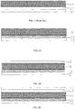
- FIG. 1 illustrates a schematic view of a structure of an existing wavelength conversion device.
- the existing wavelength conversion device includes a wavelength conversion material layer 10', a light-filtering layer 30', and a dielectric layer 20'.
- the wavelength conversion material layer 10' is configured on one side of an excitation light source
- the light-filtering layer 30' is disposed on one side of the wavelength conversion material layer 10' facing towards the excitation light source
- the dielectric layer 20' is sandwiched between the wavelength conversion material layer 10' and the light-filtering layer 30'.
- An operation process of the above-described wavelength conversion device is as follows. Excitation light emitted by the excitation light source traverses the light-filtering layer to illuminate the wavelength conversion material layer and excite the wavelength conversion material layer to generate excited light; a part of the excited light traverses the wavelength conversion material layer and emitted there-out, and the rest of the excited light as well as the excitation light unabsorbed by the wavelength conversion material are scattered to the light-filtering layer by the diffuse reflection effect and are further reflected back to the wavelength conversion material layer via the light-filtering layer. Accordingly, the rest of the excited light and the excitation light unabsorbed by the wavelength conversion material can be secondarily utilized, thus improving the utilization rate of the excitation light and the excited light.
- the dielectric layer has a relatively low refractivity and can utilize all reflection to reflect large-angle light (including unabsorbed excitation light unabsorbed) from the wavelength conversion material layer back to the wavelength conversion material layer. Accordingly, excitation light unabsorbed by the wavelength conversion material layer can be secondarily utilized, thus further improving the conversion efficiency of the wavelength conversion device.
- the present disclosure aims at providing a wavelength conversion device, a light source system and a projection system to solve the issues in existing techniques that the heat generated by the wavelength conversion material layer is hardly to be conducted out.
- the present disclosure provides a wavelength conversion device including a wavelength conversion material layer and a first light-filtering layer disposed on a first side of the wavelength conversion material layer.
- the wavelength conversion device also includes a first thermally-conductive dielectric layer configured between the wavelength conversion material layer and the first light-filtering layer.
- the thermal conductivity of the first thermally-conductive dielectric layer is greater than or equal to the thermal conductivity of the wavelength conversion material layer, and the refractivity of the first thermally-conductive dielectric layer is less than the refractivity of the wavelength conversion material layer.
- the first thermally-conductive dielectric layer is a porous structure layer containing thermally-conductive particles.
- the first thermally-conductive dielectric layer covers the surface of the first light-filtering layer, and the contact area between the thermally-conductive particles and the first light-filtering layer accounts for 10%-50% of the total area of the first light-filtering layer.
- the thickness of the first thermally-conductive dielectric layer is less than 40 ⁇ m, and more preferentially less than 20 ⁇ m.
- the first thermally-conductive dielectric layer is made of thermally-conductive dielectric composites containing thermally-conductive particles and glass powders.
- the first thermally-conductive dielectric layer is made of thermally-conductive particles treated by a silane coupling agent.
- the volume fraction of the silane coupling agent on surface of the thermally-conductive particles in the first thermally-conductive dielectric layer is 0.1 %-1 %, and the silane coupling agent is preferentially KH550, KH560, or KH570.
- the wavelength conversion material layer is a silica gel-phosphor powder layer made of phosphor powders and silica gel.
- the wavelength conversion material layer is a luminescent glass made of phosphor powders and glass powders.
- the thermal conductivity of the thermally-conductive particles is greater than 10 W/mK.
- the thermally-conductive particles are one or more materials selected from diamond, carbon nanotubes, graphene, aluminum nitride, silicon nitride, silicon carbide, boron nitride, aluminum oxide, zinc oxide, and barium sulfate.
- the thermally-conductive particles are flake-like or fiber-like, and the thermally-conductive particles are white or transparent.
- the particle size of the thermally-conductive particles is 0.1 ⁇ m-20 ⁇ m.
- the wavelength conversion device also includes a second light-filtering layer disposed on a second side of the wavelength conversion material layer.
- the wavelength conversion device also includes a dielectric layer sandwiched between the wavelength conversion material layer and the second light-filtering layer, and the refractivity of the dielectric layer is less than the refractivity of the wavelength conversion material layer.
- the wavelength conversion device also includes a second thermally-conductive dielectric layer sandwiched between the wavelength conversion material layer and the second thermally-conductive dielectric layer, the thermal conductivity of the second thermally-conductive dielectric layer is greater than or equal to the thermal conductivity of the wavelength conversion material layer, and the refractivity of the second thermally-conductive dielectric layer is less than the refractivity of the wavelength conversion material layer.
- the second thermally-conductive dielectric layer has the same feature as the first thermally-conductive dielectric layer described above in the present disclosure.
- the present disclosure also provides a light source system including an excitation light source and a wavelength conversion device.
- the wavelength conversion device is a wavelength conversion device described above in the present disclosure.
- the present disclosure also provides a projection system including a projection unit and a light source system.
- the light source system is a light source system described above in the present disclosure.
- a first thermally-conductive dielectric layer is configured between the wavelength conversion material layer and the first light-filtering layer.
- the refractivity of the first thermally-conductive dielectric layer is less than the refractivity of the wavelength conversion material layer, and the thermal conductivity of the first thermally-conductive dielectric layer is greater than or equal to the thermal conductivity of the wavelength conversion material layer.
- spatially relative terms such as “on”, “above”, “on surface of”, “upper” may be used to describe the spatial relationship between one device or features and other devices or features illustrated in the figures. It should be understood that, spatially relative terms are intended to encompass different orientations of the device in use or operation in addition to the orientation depicted in the figures. For example, if the device in the figures is turned over, the device described as “above other devices or configurations” or “on other devices or configurations” will later, be defined as “below other devices or configurations", or “beneath other devices or configurations”. Accordingly, the exemplary term “above” may include both an orientation of “above” or “below”. The device may be otherwise oriented (rotated by 90 degrees or at other orientations), and the spatially relative descriptors used herein may be interpreted accordingly.
- the wavelength conversion device may include a wavelength conversion material layer 10 and a first light-filtering layer 30 disposed on a first side of the wavelength conversion material layer 10.
- the wavelength conversion device may also include a first thermally-conductive dielectric layer 20 sandwiched between the wavelength conversion material layer 10 and the first light-filtering layer 30.
- the thermal conductivity of the first thermally-conductive dielectric layer 20 may be greater than or equal to the thermal conductivity of the wavelength conversion material layer 10.
- the refractivity of the first thermally-conductive dielectric layer 20 may be less than the refractivity of the wavelength conversion material layer 10.
- the first side may refer to the light incident side of the wavelength conversion material layer.
- heat generated by the wavelength conversion material layer 10 may be conducted towards the first side of the wavelength conversion material layer 10 via the first thermally-conductive dielectric layer 20. Accordingly, the heat generated by the wavelength conversion material layer 10 may be timely conducted out, and brightness and stability of the excited light produced by the wavelength conversion device may be further improved.
- the refractivity of the first thermally-conductive dielectric layer 20 may be less than the refractivity of the wavelength conversion material layer 10, such that large-angle light (including excitation light) from the wavelength conversion material layer 10 may be reflected back to the wavelength conversion material layer 10. Accordingly, excitation light unabsorbed by the wavelength conversion material layer 10 may be secondarily utilized, thus improving the conversion efficiency of the excitation light generated by the wavelength conversion device.
- the first thermally-conductive dielectric layer 20 may be a porous structural layer containing thermally-conductive particles.
- the thermally-conductive particles may be stacked and connected with one another to form a reticular structure, and porous structures may form between the thermally-conductive particles.
- the reticular structure in the first thermally-conductive dielectric layer 20 may timely conduct out the heat generated by the wavelength conversion material layer 10, thus avoiding deterioration of the wavelength conversion material caused by high temperature. Accordingly, the brightness of the excited light generated by the wavelength conversion device and the thermal stability of the wavelength conversion material layer 10 may be improved. Meanwhile, the porous structures may ensure that the excitation light and the excited light can traverse the first thermally-conductive dielectric layer 20 to illuminate the wavelength conversion material layer 10. Further, the excitation light and the excited light may be scattered to the first light-filtering layer 30 by the diffuse reflection effect of the wavelength conversion material layer 10, and further be reflected back to the wavelength conversion material layer 10 by the first light-filtering layer 30.
- the excited light may be secondarily utilized, thus improving the conversion efficiency of the excitation light.
- the pores in the first thermally-conductive dielectric layer 20 may be filled with air, thus improving the reflection effect of the interface between the first thermally-conductive dielectric layer 20 and the wavelength conversion material layer 10 on the large-angle light from the wavelength conversion material layer 10.
- the heat generated by the wavelength conversion material layer 10 may be conducted mainly through the contact area between the thermally-conductive particles in the first thermally-conductive dielectric layer 20 and the first light-filtering layer 30.
- the larger the contact area the better the thermal conductive (heat dissipation) effect of the first thermally-conductive dielectric layer 20, and the poorer the reflection effects of the first light-filtering layer towards the excited light, which is not beneficial for light to traverse the first thermally-conductive dielectric layer 20.
- the contact area between the thermally-conductive particles in the first thermally-conductive dielectric layer 20 and the first light-filtering layer 30 may be 10%-50% of the total area of the first light-filtering layer 30.
- the thickness of the first thermally-conductive dielectric layer 20 may be less than 40 ⁇ m, and more preferentially less than 20 ⁇ m.
- the first thermally-conductive dielectric layer 20 with an above-described thickness may show better thermal conductive (heat dissipation) effect.
- the first thermally-conductive dielectric layer 20 may be made of thermally-conductive dielectric composites containing thermally-conductive particles, or thermally-conductive dielectric composites containing thermally-conductive particles and glass powders. More preferentially, the first thermally-conductive dielectric layer 20 may be made of thermally-conductive particles treated by a silane coupling agent.
- a method that uses the silane coupling agent to treat the surface of the thermally-conductive particles may include using the silane coupling agent to carry out an immersion treatment of a thermally-conductive dielectric pre-layer formed by compressing the thermally-conductive dielectric composites containing the thermally-conductive particles.
- silane may be coupled with and attached to the surface of the thermally-conductive particles in the thermally-conductive dielectric pre-layer, thus forming the first thermally-conductive dielectric layer.
- the silane coupling agent may be used to perform surface coating of the thermally-conductive particles, and the thermally-conductive particles covered by the silane coupling agent may be brush-coated to form the first thermally-conductive dielectric layer.
- Silane coupling agents may be a type of special organic functional compound with one end of the molecular chain being an organophilic group and another end of the molecular chain being an inorganophilic group. Accordingly, by using the silane coupling agent to treat the thermally-conductive particles in the thermally-conductive dielectric preliminary layer, on one hand, an adhesive force between the thermally-conductive particles in the first thermally-conductive dielectric layer 20 may be enhanced, and on another hand, an adhesive force between the thermally-conductive particles in the first thermally-conductive dielectric layer 20 and the first light-filtering layer 30 may be enhanced. Accordingly, the thermal conductive (heat dissipation) effect of the first thermally-conductive dielectric layer 20 may be further improved.
- the volume fraction of the silane coupling agent on surface of the thermally-conductive particles in the first thermally-conductive dielectric layer 20 may be 0.1 %-1 %, and the silane coupling agent may preferentially be KH550, KH560, or KH570.
- the above-described silane coupling agent may not only have relatively good adhesive ability, but also have relatively good heat-resistant performance.
- the type and fabrication process of the first thermally-conductive dielectric layer 20 may be related to the type of the wavelength conversion material layer 10.
- the first thermally-conductive dielectric layer 20 may be made of thermally-conductive dielectric composites containing thermally-conductive particles.
- the wavelength conversion material layer 10 is a luminescent glass made of phosphor powders and glass powders
- the first thermally-conductive dielectric layer 20 may be made of thermally-conductive dielectric composites containing thermally-conductive particles, or made of thermally-conductive dielectric composites containing thermally-conductive particles and glass powders.
- the silica gel-phosphor powder layer may be formed by solidification of the phosphor powders and the silica gel.
- the luminescent glass may be formed by sintering the phosphor powders and the glass powders.
- the thermally-conductive dielectric composites may be disposed on the wavelength conversion material layer 10 via processes such as spraying, brush painting, or silk-screen printing, etc. Specific parameters of the above-mentioned processes may be configured according to existing techniques, which are not repeatedly described here.
- the wavelength conversion material layer 10 may be a silica gel-phosphor powder layer or a luminescent glass.
- the first thermally-conductive dielectric layer 20 may also be formed by compressing the thermally-conductive dielectric composites containing the thermally-conductive particles, and then using silane coupling agent to treat the surface of the thermally-conductive particles.
- the thermal conductivity of the thermally-conductive particles in the first thermally-conductive dielectric layer 20 may be greater than 10 W/mK. More preferentially, the thermally-conductive particles may be one or more materials selected from diamond, carbon nanotubes, graphene, aluminum nitride, silicon nitride, silicon carbide, boron nitride, aluminum oxide, zinc oxide, or barium sulfate.
- the thermally-conductive particles may be stacked and connected with one another to form a reticular structure, and the reticular structure may timely conduct out the heat generated by the wavelength conversion material layer 10.
- the thermal conductive effect of the reticular structure may be related to the shape and dimension of the thermally-conductive particles.
- the thermally-conductive particles may be flake-like or fiber-like, and the flake-like or fiber-like thermally-conductive particles may be stacked and better connected with one another to form the reticular structure.
- the particle size of the thermally-conductive particles may be 0.1 ⁇ m-20 ⁇ m.
- the particle size of the thermally-conductive particles may refer to the maximum length of the thermally-conductive particles in a three-dimensional space.
- the particle size of the fiber-like thermally-conductive particles may refer to the length of the fiber-like thermally-conductive particles.
- the thermally-conductive particles may preferentially be white or transparent.
- the above-described wavelength conversion device may include other structures, and is not limited to include the wavelength conversion material layer 10, the first light-filtering layer 30, and the first thermally-conductive dielectric layer 20.
- the wavelength conversion device may also include a second light-filtering layer 40 disposed on a second side of the wavelength conversion material layer 10, and the structure of the wavelength conversion device is shown in FIG. 2B .
- the operation process of the wavelength conversion device may be implemented as follows. The excitation light emitted by the excitation light source may traverse the first light-filtering layer 30 to illuminate the wavelength conversion material layer 10 and excite the wavelength conversion material layer 10 to generate excited light.
- the excited light may illuminate the second light-filtering layer 40, small-angle excited light may traverse the second light-filtering layer 40, and large-angle excited light may be reflected back to the wavelength conversion material layer 10 by the second light-filtering layer 40. Then, the wavelength conversion material layer 10 may scatter and reflect the large-angle excited light back to the second light-filtering layer 40 by the diffuse reflection effect, and after several such processes, all the excited light may be emitted at small angles, thus improving the light utilization rate of the emergent light.
- the second side may refer to the light-emitting side of the wavelength conversion material layer.
- the first light-filtering layer 30 and the second light-filtering layer 40 may be common light-filtering films in the art.
- the first light-filtering layer 30 and the second light-filtering layer 40 may be two-layer or more than two-layer dielectric films made of materials with different optical refractivity, for example, hollow optical thin films.
- the first light-filtering layer 30 and the second light-filtering layer 40 may also be optical thin films containing regularly distributed photonic crystals, or combined films of the optical thin films and the dielectric films made of materials with different optical refractivity as described above.
- the wavelength conversion device may also include a dielectric layer 50 (the structure illustrated in FIG. 2C ) sandwiched between the wavelength conversion material layer 10 and the second light-filtering layer 40.
- the refractivity of the dielectric layer 50 may be less than the refractivity of the wavelength conversion material layer 10.
- the dielectric layer 50 may have relatively low refractivity, such that all reflection may be utilized to reflect the large-angle light from the wavelength conversion material layer 10 to the wavelength conversion material layer 10. Accordingly, excitation light unabsorbed by the wavelength conversion material layer 10 may be secondarily utilized, and large-angle excited light may be scattered to become small-angle light by the wavelength conversion material for emission, thus further improving the conversion efficiency of the excitation light and the light utilization rate.
- the dielectric layer 50 may be made of a dielectric material with a low refractivity.
- the dielectric layer 50 may be an air dielectric layer sandwiched between the wavelength conversion material layer 10 and the second light-filtering layer 40.
- the wavelength conversion device may also include a second thermally-conductive dielectric layer 60 (the structure illustrated in FIG. 2D ) sandwiched between the wavelength conversion material layer 10 and the second light-filtering layer 40.
- the thermal conductivity of the second thermally-conductive dielectric layer 60 may be greater than or equal to the thermal conductivity of the wavelength conversion material layer 10, and the refractivity of the second thermally-conductive dielectric layer 60 may be less than the refractivity of the wavelength conversion material layer 10.
- the second thermally-conductive dielectric layer 60 may have the same properties as the disclosed first thermally-conductive dielectric layer 20.
- the heat generated by the wavelength conversion material layer 10 may be conducted towards the second side of the wavelength conversion material layer 10 via the second thermally-conductive dielectric layer 60.
- the heat generated by the wavelength conversion material layer 1010 may be more timely conducted out, thus further improving the brightness and stability of the excited light generated by the wavelength conversion device.
- the refractivity of the second thermally-conductive dielectric layer 60 may be less than the thermal conductivity of the wavelength conversion material layer 10, such that large-angle light from the wavelength conversion material layer 10 may be reflected back to the wavelength conversion material layer 10.
- the excitation light unabsorbed by the wavelength conversion material layer 10 may be secondarily utilized, and the large-angle excited light may be scattered to be small-angle light via the wavelength conversion material for emission, thus further improving the conversion efficiency of the excitation light generated by the wavelength conversion device and the light utilization rate.
- the present disclosure also provides a light source system including an excitation light source and a wavelength conversion device.
- the wavelength conversion device may be a wavelength conversion device described above in the present disclosure.
- the heat generated by the wavelength conversion material layer in the wavelength conversion device may be timely conducted out, thus improving the brightness and stability of the excited light generated by the wavelength conversion device. Accordingly, the brightness and stability of the light source system may be improved.
- the present disclosure also provides a projection system including a projection unit and a light source system.
- the light source system may be a light source system described above in the present disclosure.
- the light brightness and stability of the light source system in the projection system may be improved, thus satisfying the requirements of light brightness for the projection system in use.
- the wavelength conversion device may include a wavelength conversion material layer, a first light-filtering layer disposed on a first side of the wavelength conversion material layer, a first thermally-conductive dielectric layer sandwiched between the wavelength conversion material layer and the first light-filtering layer, a second light-filtering layer disposed on a second side of the wavelength conversion material layer, and a second thermally-conductive dielectric layer sandwiched between the wavelength conversion material layer and the second light-filtering layer.
- the wavelength conversion material layer may be a luminescent glass formed by sintering phosphor powders and glass powders
- the thermal conductivity of the wavelength conversion material layer may be 5.0 W/mK
- the refractivity of the wavelength conversion material layer may be 2.2.
- the first thermally-conductive dielectric layer may be formed by silk-screen printing and pressing diamond particles (average particle size of 5 ⁇ m) on surface of the first side of the wavelength conversion material, and then using silane coupling agent (KH560) to treat the surface of the diamond particles.
- the second thermally-conductive dielectric layer may be formed by silk-screen printing and pressing diamond particles (average particle size of 5 ⁇ m) on surface of the second side of the wavelength conversion material, and then using silane coupling agent (KH560) to treat the surface of the diamond particles.
- the first thermally-conductive dielectric layer may have the following features.
- the contact area between the diamond particles in the first thermally-conductive dielectric layer and the first light-filtering layer may account for 30% of the total area of the first light-filtering layer.
- the thickness of the first thermally-conductive dielectric layer may be 3 ⁇ m.
- the thermal conductivity of the first thermally-conductive dielectric layer may be 12.8 W/mK, and the refractivity of the first thermally-conductive dielectric layer may be 1.4.
- the volume fraction of the silane coupling agent (KH560) on the surface of the diamond particle in the first thermally-conductive dielectric layer may be 1%.
- the second thermally-conductive dielectric layer may have the following features.
- the contact area between the diamond particles in the second thermally-conductive dielectric layer and the second light-filtering layer may account for 30% of the total area of the second light-filtering layer.
- the thickness of the first thermally-conductive dielectric layer may be 3 ⁇ m.
- the thermal conductivity of the thermal thermally-conductive dielectric layer may be 12.8 W/mK, and the refractivity of the second thermally-conductive dielectric layer may be 1.4.
- the volume fraction of the silane coupling agent (KH560) on the surface of the diamond particle in the second thermally-conductive dielectric layer may be 1%.
- the wavelength conversion device may include a wavelength conversion material layer, a first light-filtering layer disposed on a first side of the wavelength conversion material layer, a first thermally-conductive dielectric layer sandwiched between the wavelength conversion material layer and the first light-filtering layer, a second light-filtering layer disposed on a second side of the wavelength conversion material layer, and a dielectric layer sandwiched between the wavelength conversion material layer and the second light-filtering layer.
- the wavelength conversion material layer may be a silica gel-phosphor powder layer formed by solidification of phosphor powders and silica gel.
- the first thermally-conductive dielectric layer may be formed by brush-coating and pressing fiber-like carbon nanotubes (average particle size of 20 ⁇ m) on the wavelength conversion material layer, and then using the silane coupling agent (KH560) to treat the surface of the carbon nanotubes.
- the thermal conductivity of the wavelength conversion material layer may be 5.0 W/mK
- the refractivity of the wavelength conversion material layer may be 2.2
- the dielectric layer may be an air dielectric layer.
- the first thermally-conductive dielectric layer may have the following features.
- the contact area between the carbon nanotubes in the first thermally-conductive dielectric layer and the first light-filtering layer may account for 20% of the total area of the first light-filtering layer.
- the thickness of the first thermally-conductive dielectric layer may be 6 ⁇ m.
- the thermal conductivity of the first thermally-conductive dielectric layer may be 12.5 W/mK, and the refractivity of the first thermally-conductive dielectric layer may be 1.5.
- the volume fraction of the silane coupling agent (KH560) on the surface of the carbon nanotubes in the first thermally-conductive dielectric layer may be 1 %.
- the wavelength conversion device may include a wavelength conversion material layer, a first light-filtering layer disposed on a first side of the wavelength conversion material layer, a first thermally-conductive dielectric layer sandwiched between the wavelength conversion material layer and the first light-filtering layer, and a second light-filtering layer disposed on a second side of the wavelength conversion material layer.
- the wavelength conversion material layer may be a silica gel-phosphor powder layer formed by solidification of phosphor powders and silica gel.
- the thermal conductivity of the wavelength conversion material layer may be 5.0 W/mK, and the refractivity of the wavelength conversion material layer may be 2.2.
- the first thermally-conductive dielectric layer may be formed by spraying and pressing diamond particles (average particle size of 2 ⁇ m) onto the wavelength conversion material.
- the first thermally-conductive dielectric layer may have the following features.
- the contact area between the diamond particles in the first thermally-conductive dielectric layer and the first light-filtering layer may account for 10% of the total area of the first light-filtering layer.
- the thickness of the first thermally-conductive dielectric layer may be 20 ⁇ m.
- the thermal conductivity of the first thermally-conductive dielectric layer may be 12.4 W/mK, and the refractivity of the first thermally-conductive dielectric layer may be 1.6.
- the wavelength conversion device may include a wavelength conversion material layer, a first light-filtering layer disposed on a first side of the wavelength conversion material layer, and a first thermally-conductive dielectric layer sandwiched between the wavelength conversion material layer and the first light-filtering layer.
- the wavelength conversion material layer may be a luminescent glass formed by solidification of phosphor powders and glass powders.
- the thermal conductivity of the wavelength conversion material layer may be 5.2 W/mK, and the refractivity of the wavelength conversion material layer may be 2.3.
- the first thermally-conductive dielectric layer may be formed by silk-screen printing and sintering the diamond particles (average particle size of 2 ⁇ m) and the glass powders on the wavelength conversion material.
- the first thermally-conductive dielectric layer may have the following features.
- the contact area between the diamond particles in the first thermally-conductive dielectric layer and the first light-filtering layer may account for 50% of the total area of the first light-filtering layer.
- the thickness of the first thermally-conductive dielectric layer may be 15 ⁇ m.
- the thermal conductivity of the first thermally-conductive dielectric layer may be 13 W/mK, and the refractivity of the first thermally-conductive dielectric layer may be 1.3.
- the wavelength conversion device may include a wavelength conversion material layer, a first light-filtering layer disposed on a first side of the wavelength conversion material layer, and a first thermally-conductive dielectric layer sandwiched between the wavelength conversion material layer and the first light-filtering layer.
- the wavelength conversion material layer may be a silica gel-phosphor powder layer formed by solidification of phosphor powders and silica gel.
- the thermal conductivity of the wavelength conversion material layer may be 4.8 W/mK, and the refractivity of the wavelength conversion material layer may be 2.2.
- the first thermally-conductive dielectric layer may be formed by spraying and pressing flake-like silicon nitride particles (average particle size of 0.1 ⁇ m) on the wavelength conversion material.
- the first thermally-conductive dielectric layer may have the following features.
- the contact area between the silicon nitride particles in the first thermally-conductive dielectric layer and the first light-filtering layer may account for 8% of the total area of the first light-filtering layer.
- the thickness of the first thermally-conductive dielectric layer may be 40 ⁇ m.
- the thermal conductivity of the first thermally-conductive dielectric layer may be 12 W/mK, and the refractivity of the first thermally-conductive dielectric layer may be 1.6.
- the wavelength conversion device may include a wavelength conversion material layer, a dielectric layer and a first light-filtering layer disposed sequentially on a first side of the wavelength conversion material layer, and a dielectric layer and a first light-filtering layer disposed sequentially on another side of the wavelength conversion material.
- the wavelength conversion material layer may be a silica gel-phosphor powder layer formed by solidification of phosphor powders and silica gel
- the dielectric layer may be an air dielectric layer.
- the luminescent intensity of the wavelength conversion devices may increase as the power of the excitation light source increases.
- the luminescent intensity of the wavelength conversion devices provided by Embodiment 1 to 5 may be far higher than the luminescent intensity of the wavelength conversion device provided by the Contrast example 1.
- the luminescent intensity of the wavelength conversion device provided by Embodiment 1 to 5 may increase approximately linearly, and the luminescent intensity of the wavelength conversion device provided by Contrast example 1 may first increase, and later decrease.
- the thermally-conductive dielectric layer in the wavelength conversion devices provided by Embodiment 1 to 5 may timely conduct out the heat generated by the wavelength conversion material layer, thus improving the brightness and stability of the excited light generated by the wavelength conversion device. Accordingly, the conversion efficiency of the wavelength conversion device may be improved.
Landscapes
- Physics & Mathematics (AREA)
- General Physics & Mathematics (AREA)
- Engineering & Computer Science (AREA)
- Nonlinear Science (AREA)
- General Engineering & Computer Science (AREA)
- Optics & Photonics (AREA)
- Spectroscopy & Molecular Physics (AREA)
- Chemical & Material Sciences (AREA)
- Ceramic Engineering (AREA)
- Multimedia (AREA)
- Astronomy & Astrophysics (AREA)
- Optical Filters (AREA)
- Luminescent Compositions (AREA)
Applications Claiming Priority (2)
| Application Number | Priority Date | Filing Date | Title |
|---|---|---|---|
| CN201410201900.2A CN105093776B (zh) | 2014-05-13 | 2014-05-13 | 波长转换装置、光源系统及投影系统 |
| PCT/CN2015/078353 WO2015172670A1 (fr) | 2014-05-13 | 2015-05-06 | Dispositif de conversion de longueur d'onde, système source de lumière et système de projection |
Publications (3)
| Publication Number | Publication Date |
|---|---|
| EP3144724A1 true EP3144724A1 (fr) | 2017-03-22 |
| EP3144724A4 EP3144724A4 (fr) | 2017-12-13 |
| EP3144724B1 EP3144724B1 (fr) | 2020-07-15 |
Family
ID=54479319
Family Applications (1)
| Application Number | Title | Priority Date | Filing Date |
|---|---|---|---|
| EP15792223.8A Active EP3144724B1 (fr) | 2014-05-13 | 2015-05-06 | Dispositif de conversion de longueur d'onde, système source de lumière et système de projection |
Country Status (6)
| Country | Link |
|---|---|
| US (1) | US9897303B2 (fr) |
| EP (1) | EP3144724B1 (fr) |
| JP (1) | JP6366736B2 (fr) |
| KR (1) | KR101841229B1 (fr) |
| CN (1) | CN105093776B (fr) |
| WO (1) | WO2015172670A1 (fr) |
Families Citing this family (23)
| Publication number | Priority date | Publication date | Assignee | Title |
|---|---|---|---|---|
| CN104701353A (zh) * | 2015-03-27 | 2015-06-10 | 京东方科技集团股份有限公司 | 有机发光显示面板和显示装置 |
| CN105371254A (zh) * | 2015-11-27 | 2016-03-02 | 海信集团有限公司 | 一种波长转换装置及其制备方法、激光光源装置 |
| CN205447345U (zh) * | 2016-03-01 | 2016-08-10 | 深圳市绎立锐光科技开发有限公司 | 一种波长转换装置和光源系统 |
| JP6852976B2 (ja) * | 2016-03-29 | 2021-03-31 | 日本特殊陶業株式会社 | 波長変換部材、その製造方法および発光装置 |
| CN105884203A (zh) * | 2016-04-07 | 2016-08-24 | 薛信培 | 复合高硼硅玻璃及其制备方法和led灯饰 |
| CN106382474B (zh) * | 2016-10-17 | 2019-12-10 | 纳晶科技股份有限公司 | 光致发光器件及具有其的发光器件 |
| CN106292074B (zh) * | 2016-10-17 | 2020-03-31 | 纳晶科技股份有限公司 | 光致发光器件及具有其的发光器件 |
| CN108267914B (zh) * | 2016-12-30 | 2022-01-11 | 中强光电股份有限公司 | 波长转换装置及其投影机 |
| CN110799877B (zh) * | 2017-04-24 | 2022-07-08 | 亮锐控股有限公司 | 高亮度光转换装置 |
| CN108803213B (zh) | 2017-04-27 | 2021-03-19 | 中强光电股份有限公司 | 波长转换滤光模块以及照明系统 |
| CN207350253U (zh) * | 2017-05-24 | 2018-05-11 | 深圳市光峰光电技术有限公司 | 波长转换装置 |
| DE102017220940A1 (de) * | 2017-11-23 | 2019-05-23 | Osram Gmbh | Konverter für eine Konversionsleuchte mit Wärmeleitschicht |
| CN114518650A (zh) * | 2018-04-12 | 2022-05-20 | 深圳光峰科技股份有限公司 | 色轮组件及光源系统及投影设备 |
| CN110737085B (zh) * | 2018-07-18 | 2021-11-30 | 深圳光峰科技股份有限公司 | 波长转换装置 |
| CN110837199B (zh) * | 2018-08-16 | 2021-10-12 | 深圳光峰科技股份有限公司 | 显示设备 |
| CN110938429B (zh) * | 2018-09-25 | 2021-10-26 | 深圳光峰科技股份有限公司 | 一种波长转换材料 |
| CN111103748A (zh) * | 2018-10-29 | 2020-05-05 | 深圳光峰科技股份有限公司 | 波长转换装置及光源系统 |
| CN111370563A (zh) * | 2018-12-25 | 2020-07-03 | 弗洛里光电材料(苏州)有限公司 | 复合荧光胶膜及其应用 |
| CN109445191B (zh) * | 2019-01-02 | 2022-05-13 | 京东方科技集团股份有限公司 | 发光件及其制作方法、背光源和显示装置 |
| CN111474817A (zh) * | 2019-01-24 | 2020-07-31 | 中强光电股份有限公司 | 波长转换模块以及投影装置 |
| JP6730479B1 (ja) * | 2019-03-06 | 2020-07-29 | 株式会社ダイセル | 表面修飾ナノダイヤモンド、ナノダイヤモンド分散組成物、及び表面修飾ナノダイヤモンドの製造方法 |
| CN110818248B (zh) * | 2019-11-22 | 2022-05-27 | 广州光联电子科技有限公司 | 一种高导热、高折射率荧光玻璃层及其制备方法 |
| CN115981085B (zh) | 2021-10-15 | 2026-04-28 | 中强光电股份有限公司 | 转轮的制造方法、转轮以及投影装置 |
Family Cites Families (24)
| Publication number | Priority date | Publication date | Assignee | Title |
|---|---|---|---|---|
| CA2116950A1 (fr) * | 1993-03-22 | 1994-09-23 | Pamela K. Whitman | Lampe a filtre infrarouge et revetement diffusant |
| US5545473A (en) * | 1994-02-14 | 1996-08-13 | W. L. Gore & Associates, Inc. | Thermally conductive interface |
| JP2001249370A (ja) * | 2000-03-07 | 2001-09-14 | Japan Organo Co Ltd | 非線形光学素子及びその製造方法 |
| CN100378567C (zh) * | 2003-03-11 | 2008-04-02 | 日本碍子株式会社 | 波长变换元件 |
| US7196354B1 (en) * | 2005-09-29 | 2007-03-27 | Luminus Devices, Inc. | Wavelength-converting light-emitting devices |
| KR100764391B1 (ko) * | 2006-04-25 | 2007-10-05 | 삼성전기주식회사 | 발광 다이오드 모듈 |
| TW200847489A (en) * | 2007-02-27 | 2008-12-01 | Kyocera Corp | Light-emitting device |
| CN101539270B (zh) * | 2008-03-17 | 2011-06-08 | 绎立锐光科技开发(深圳)有限公司 | 具有发射角度选择特性的光波长转换方法 |
| US8410681B2 (en) * | 2008-06-30 | 2013-04-02 | Bridgelux, Inc. | Light emitting device having a refractory phosphor layer |
| DE102008063634B4 (de) * | 2008-12-18 | 2021-03-11 | OSRAM Opto Semiconductors Gesellschaft mit beschränkter Haftung | Leuchtmittel und Projektor mit mindestens einem solchen Leuchtmittel |
| WO2010123052A1 (fr) * | 2009-04-22 | 2010-10-28 | シーシーエス株式会社 | Dispositif électroluminescent |
| JP5491888B2 (ja) * | 2010-02-05 | 2014-05-14 | 日立コンシューマエレクトロニクス株式会社 | 投写型表示装置 |
| CN103221180A (zh) * | 2010-09-21 | 2013-07-24 | 铼钻科技股份有限公司 | 具有基本平坦颗粒尖端的超研磨工具及其相关方法 |
| JP5760397B2 (ja) * | 2010-11-15 | 2015-08-12 | 日立化成株式会社 | 熱伝導シート、熱伝導シートの製造方法、及び放熱装置 |
| JP5733743B2 (ja) * | 2010-12-15 | 2015-06-10 | 日東電工株式会社 | 光半導体装置 |
| US20140003074A1 (en) * | 2011-03-16 | 2014-01-02 | Katsuhiko Kishimoto | Wavelength conversion member and method for manufacturing the same, and light-emitting device, illuminating device, and headlight |
| JPWO2012132232A1 (ja) * | 2011-03-31 | 2014-07-24 | パナソニック株式会社 | 半導体発光装置 |
| CN102437272B (zh) * | 2011-11-25 | 2014-01-01 | 深圳市光峰光电技术有限公司 | 波长转换装置和发光装置 |
| JP5966501B2 (ja) * | 2012-03-28 | 2016-08-10 | 日亜化学工業株式会社 | 波長変換用無機成形体及びその製造方法、並びに発光装置 |
| WO2014030100A1 (fr) * | 2012-08-24 | 2014-02-27 | Koninklijke Philips N.V. | Dispositif d'éclairage |
| JP2014052606A (ja) * | 2012-09-10 | 2014-03-20 | Sharp Corp | 蛍光体基板、発光デバイス、表示装置、及び照明装置 |
| CA2905653C (fr) * | 2013-03-19 | 2020-06-23 | Sony Corporation | Separateur, batterie, bloc de batteries, appareil electronique, vehicule electrique, dispositif de stockage d'energie, et systeme d'energie |
| CN203489181U (zh) * | 2013-10-15 | 2014-03-19 | 深圳市光峰光电技术有限公司 | 色轮及其光源系统、投影系统 |
| JP6364257B2 (ja) * | 2013-11-20 | 2018-07-25 | 日本碍子株式会社 | 光学部品 |
-
2014
- 2014-05-13 CN CN201410201900.2A patent/CN105093776B/zh active Active
-
2015
- 2015-05-06 WO PCT/CN2015/078353 patent/WO2015172670A1/fr not_active Ceased
- 2015-05-06 EP EP15792223.8A patent/EP3144724B1/fr active Active
- 2015-05-06 US US15/310,396 patent/US9897303B2/en active Active
- 2015-05-06 JP JP2016567679A patent/JP6366736B2/ja active Active
- 2015-05-06 KR KR1020167034642A patent/KR101841229B1/ko active Active
Also Published As
| Publication number | Publication date |
|---|---|
| EP3144724B1 (fr) | 2020-07-15 |
| JP6366736B2 (ja) | 2018-08-01 |
| CN105093776A (zh) | 2015-11-25 |
| US20170167710A1 (en) | 2017-06-15 |
| JP2017519240A (ja) | 2017-07-13 |
| EP3144724A4 (fr) | 2017-12-13 |
| US9897303B2 (en) | 2018-02-20 |
| CN105093776B (zh) | 2020-08-25 |
| KR101841229B1 (ko) | 2018-03-23 |
| KR20170008258A (ko) | 2017-01-23 |
| WO2015172670A1 (fr) | 2015-11-19 |
Similar Documents
| Publication | Publication Date | Title |
|---|---|---|
| EP3144724B1 (fr) | Dispositif de conversion de longueur d'onde, système source de lumière et système de projection | |
| US11022276B2 (en) | Wavelength conversion device, manufacturing method thereof, and related illumination device | |
| JP6731651B2 (ja) | 波長変換部材 | |
| JP5966501B2 (ja) | 波長変換用無機成形体及びその製造方法、並びに発光装置 | |
| JP5966539B2 (ja) | 波長変換用無機成形体及びその製造方法、並びに発光装置 | |
| US10777711B2 (en) | Wavelength conversion element and light emitting device | |
| KR101926475B1 (ko) | 난반사 재료, 난반사층, 파장 변환 장치 및 광원 시스템 | |
| EP3358381A1 (fr) | Élément de conversion de longueur d'onde et dispositif électroluminescent | |
| JP2013247067A5 (ja) | 波長変換用無機成形体及び発光装置 | |
| KR20130110101A (ko) | 파장 변환용 무기 성형체 및 그 제조 방법, 및 발광 장치 | |
| WO2014046173A1 (fr) | Poudre de conversion de longueur d'onde composite, composition de résine contenant la poudre de conversion de longueur d'onde composite et dispositif électroluminescent | |
| TW201316543A (zh) | 含發光磷光體之發光二極體(led)照明配置 | |
| CN103717701A (zh) | 涂布的磷光体和包含该磷光体的发光装置 | |
| TW201015742A (en) | Light emitting diode device and manufacturing method thereof | |
| JP6185928B2 (ja) | Led用の水ガラス中の蛍光体 | |
| JP2015065425A (ja) | 発光装置及びその製造方法 | |
| WO2017188191A1 (fr) | Élément de conversion de longueur d'onde, son procédé de fabrication, et dispositif électroluminescent | |
| JP7755196B2 (ja) | 透光性部材及び発光装置 | |
| KR20150055578A (ko) | 발광소자, 발광장치 및 그들의 제조방법 | |
| CN100459193C (zh) | 白光发光二极管封装结构 | |
| JP5635189B2 (ja) | 蛍光体の改良 | |
| TWI500188B (zh) | 發光裝置及其製造方法 | |
| KR20120114464A (ko) | 쉘이 형성된 그래핀 양자점, 그 제조방법 및 이를 이용한 반도체 발광소자 | |
| WO2014020897A1 (fr) | Particule de conversion de longueur d'onde, élément de conversion de longueur d'onde et dispositif d'émission de lumière | |
| CN119371201A (zh) | 一种出光光斑可调的激光照明用陶瓷荧光体及其制备方法 |
Legal Events
| Date | Code | Title | Description |
|---|---|---|---|
| STAA | Information on the status of an ep patent application or granted ep patent |
Free format text: STATUS: THE INTERNATIONAL PUBLICATION HAS BEEN MADE |
|
| PUAI | Public reference made under article 153(3) epc to a published international application that has entered the european phase |
Free format text: ORIGINAL CODE: 0009012 |
|
| STAA | Information on the status of an ep patent application or granted ep patent |
Free format text: STATUS: REQUEST FOR EXAMINATION WAS MADE |
|
| 17P | Request for examination filed |
Effective date: 20161115 |
|
| AK | Designated contracting states |
Kind code of ref document: A1 Designated state(s): AL AT BE BG CH CY CZ DE DK EE ES FI FR GB GR HR HU IE IS IT LI LT LU LV MC MK MT NL NO PL PT RO RS SE SI SK SM TR |
|
| AX | Request for extension of the european patent |
Extension state: BA ME |
|
| DAV | Request for validation of the european patent (deleted) | ||
| DAX | Request for extension of the european patent (deleted) | ||
| A4 | Supplementary search report drawn up and despatched |
Effective date: 20171115 |
|
| RIC1 | Information provided on ipc code assigned before grant |
Ipc: F21V 9/08 20060101ALI20171109BHEP Ipc: G03B 21/20 20060101ALI20171109BHEP Ipc: G03B 21/16 20060101ALI20171109BHEP Ipc: G02F 1/35 20060101AFI20171109BHEP Ipc: F21V 29/502 20150101ALI20171109BHEP Ipc: F21V 9/16 20060101ALI20171109BHEP Ipc: F21V 29/85 20150101ALI20171109BHEP |
|
| RAP1 | Party data changed (applicant data changed or rights of an application transferred) |
Owner name: APPOTRONICS CORPORATION LIMITED |
|
| RAP1 | Party data changed (applicant data changed or rights of an application transferred) |
Owner name: APPOTRONICS CORPORATION LIMITED |
|
| RIC1 | Information provided on ipc code assigned before grant |
Ipc: G03B 21/16 20060101ALI20191108BHEP Ipc: F21V 9/08 20180101ALI20191108BHEP Ipc: G02F 1/35 20060101AFI20191108BHEP Ipc: F21V 29/502 20150101ALI20191108BHEP Ipc: F21V 29/85 20150101ALI20191108BHEP Ipc: G03B 21/20 20060101ALI20191108BHEP |
|
| GRAP | Despatch of communication of intention to grant a patent |
Free format text: ORIGINAL CODE: EPIDOSNIGR1 |
|
| STAA | Information on the status of an ep patent application or granted ep patent |
Free format text: STATUS: GRANT OF PATENT IS INTENDED |
|
| INTG | Intention to grant announced |
Effective date: 20200103 |
|
| GRAJ | Information related to disapproval of communication of intention to grant by the applicant or resumption of examination proceedings by the epo deleted |
Free format text: ORIGINAL CODE: EPIDOSDIGR1 |
|
| STAA | Information on the status of an ep patent application or granted ep patent |
Free format text: STATUS: REQUEST FOR EXAMINATION WAS MADE |
|
| GRAR | Information related to intention to grant a patent recorded |
Free format text: ORIGINAL CODE: EPIDOSNIGR71 |
|
| GRAS | Grant fee paid |
Free format text: ORIGINAL CODE: EPIDOSNIGR3 |
|
| STAA | Information on the status of an ep patent application or granted ep patent |
Free format text: STATUS: GRANT OF PATENT IS INTENDED |
|
| GRAA | (expected) grant |
Free format text: ORIGINAL CODE: 0009210 |
|
| STAA | Information on the status of an ep patent application or granted ep patent |
Free format text: STATUS: THE PATENT HAS BEEN GRANTED |
|
| INTC | Intention to grant announced (deleted) | ||
| AK | Designated contracting states |
Kind code of ref document: B1 Designated state(s): AL AT BE BG CH CY CZ DE DK EE ES FI FR GB GR HR HU IE IS IT LI LT LU LV MC MK MT NL NO PL PT RO RS SE SI SK SM TR |
|
| INTG | Intention to grant announced |
Effective date: 20200610 |
|
| REG | Reference to a national code |
Ref country code: CH Ref legal event code: EP Ref country code: GB Ref legal event code: FG4D |
|
| REG | Reference to a national code |
Ref country code: IE Ref legal event code: FG4D |
|
| REG | Reference to a national code |
Ref country code: DE Ref legal event code: R096 Ref document number: 602015055858 Country of ref document: DE |
|
| REG | Reference to a national code |
Ref country code: AT Ref legal event code: REF Ref document number: 1291681 Country of ref document: AT Kind code of ref document: T Effective date: 20200815 |
|
| REG | Reference to a national code |
Ref country code: LT Ref legal event code: MG4D |
|
| REG | Reference to a national code |
Ref country code: AT Ref legal event code: MK05 Ref document number: 1291681 Country of ref document: AT Kind code of ref document: T Effective date: 20200715 |
|
| REG | Reference to a national code |
Ref country code: NL Ref legal event code: MP Effective date: 20200715 |
|
| PG25 | Lapsed in a contracting state [announced via postgrant information from national office to epo] |
Ref country code: AT Free format text: LAPSE BECAUSE OF FAILURE TO SUBMIT A TRANSLATION OF THE DESCRIPTION OR TO PAY THE FEE WITHIN THE PRESCRIBED TIME-LIMIT Effective date: 20200715 Ref country code: SE Free format text: LAPSE BECAUSE OF FAILURE TO SUBMIT A TRANSLATION OF THE DESCRIPTION OR TO PAY THE FEE WITHIN THE PRESCRIBED TIME-LIMIT Effective date: 20200715 Ref country code: LT Free format text: LAPSE BECAUSE OF FAILURE TO SUBMIT A TRANSLATION OF THE DESCRIPTION OR TO PAY THE FEE WITHIN THE PRESCRIBED TIME-LIMIT Effective date: 20200715 Ref country code: BG Free format text: LAPSE BECAUSE OF FAILURE TO SUBMIT A TRANSLATION OF THE DESCRIPTION OR TO PAY THE FEE WITHIN THE PRESCRIBED TIME-LIMIT Effective date: 20201015 Ref country code: PT Free format text: LAPSE BECAUSE OF FAILURE TO SUBMIT A TRANSLATION OF THE DESCRIPTION OR TO PAY THE FEE WITHIN THE PRESCRIBED TIME-LIMIT Effective date: 20201116 Ref country code: FI Free format text: LAPSE BECAUSE OF FAILURE TO SUBMIT A TRANSLATION OF THE DESCRIPTION OR TO PAY THE FEE WITHIN THE PRESCRIBED TIME-LIMIT Effective date: 20200715 Ref country code: GR Free format text: LAPSE BECAUSE OF FAILURE TO SUBMIT A TRANSLATION OF THE DESCRIPTION OR TO PAY THE FEE WITHIN THE PRESCRIBED TIME-LIMIT Effective date: 20201016 Ref country code: NO Free format text: LAPSE BECAUSE OF FAILURE TO SUBMIT A TRANSLATION OF THE DESCRIPTION OR TO PAY THE FEE WITHIN THE PRESCRIBED TIME-LIMIT Effective date: 20201015 Ref country code: ES Free format text: LAPSE BECAUSE OF FAILURE TO SUBMIT A TRANSLATION OF THE DESCRIPTION OR TO PAY THE FEE WITHIN THE PRESCRIBED TIME-LIMIT Effective date: 20200715 Ref country code: HR Free format text: LAPSE BECAUSE OF FAILURE TO SUBMIT A TRANSLATION OF THE DESCRIPTION OR TO PAY THE FEE WITHIN THE PRESCRIBED TIME-LIMIT Effective date: 20200715 |
|
| PG25 | Lapsed in a contracting state [announced via postgrant information from national office to epo] |
Ref country code: LV Free format text: LAPSE BECAUSE OF FAILURE TO SUBMIT A TRANSLATION OF THE DESCRIPTION OR TO PAY THE FEE WITHIN THE PRESCRIBED TIME-LIMIT Effective date: 20200715 Ref country code: RS Free format text: LAPSE BECAUSE OF FAILURE TO SUBMIT A TRANSLATION OF THE DESCRIPTION OR TO PAY THE FEE WITHIN THE PRESCRIBED TIME-LIMIT Effective date: 20200715 Ref country code: PL Free format text: LAPSE BECAUSE OF FAILURE TO SUBMIT A TRANSLATION OF THE DESCRIPTION OR TO PAY THE FEE WITHIN THE PRESCRIBED TIME-LIMIT Effective date: 20200715 Ref country code: IS Free format text: LAPSE BECAUSE OF FAILURE TO SUBMIT A TRANSLATION OF THE DESCRIPTION OR TO PAY THE FEE WITHIN THE PRESCRIBED TIME-LIMIT Effective date: 20201115 |
|
| PG25 | Lapsed in a contracting state [announced via postgrant information from national office to epo] |
Ref country code: NL Free format text: LAPSE BECAUSE OF FAILURE TO SUBMIT A TRANSLATION OF THE DESCRIPTION OR TO PAY THE FEE WITHIN THE PRESCRIBED TIME-LIMIT Effective date: 20200715 |
|
| REG | Reference to a national code |
Ref country code: DE Ref legal event code: R097 Ref document number: 602015055858 Country of ref document: DE |
|
| PG25 | Lapsed in a contracting state [announced via postgrant information from national office to epo] |
Ref country code: SM Free format text: LAPSE BECAUSE OF FAILURE TO SUBMIT A TRANSLATION OF THE DESCRIPTION OR TO PAY THE FEE WITHIN THE PRESCRIBED TIME-LIMIT Effective date: 20200715 Ref country code: RO Free format text: LAPSE BECAUSE OF FAILURE TO SUBMIT A TRANSLATION OF THE DESCRIPTION OR TO PAY THE FEE WITHIN THE PRESCRIBED TIME-LIMIT Effective date: 20200715 Ref country code: EE Free format text: LAPSE BECAUSE OF FAILURE TO SUBMIT A TRANSLATION OF THE DESCRIPTION OR TO PAY THE FEE WITHIN THE PRESCRIBED TIME-LIMIT Effective date: 20200715 Ref country code: CZ Free format text: LAPSE BECAUSE OF FAILURE TO SUBMIT A TRANSLATION OF THE DESCRIPTION OR TO PAY THE FEE WITHIN THE PRESCRIBED TIME-LIMIT Effective date: 20200715 Ref country code: DK Free format text: LAPSE BECAUSE OF FAILURE TO SUBMIT A TRANSLATION OF THE DESCRIPTION OR TO PAY THE FEE WITHIN THE PRESCRIBED TIME-LIMIT Effective date: 20200715 Ref country code: IT Free format text: LAPSE BECAUSE OF FAILURE TO SUBMIT A TRANSLATION OF THE DESCRIPTION OR TO PAY THE FEE WITHIN THE PRESCRIBED TIME-LIMIT Effective date: 20200715 |
|
| PLBE | No opposition filed within time limit |
Free format text: ORIGINAL CODE: 0009261 |
|
| STAA | Information on the status of an ep patent application or granted ep patent |
Free format text: STATUS: NO OPPOSITION FILED WITHIN TIME LIMIT |
|
| PG25 | Lapsed in a contracting state [announced via postgrant information from national office to epo] |
Ref country code: AL Free format text: LAPSE BECAUSE OF FAILURE TO SUBMIT A TRANSLATION OF THE DESCRIPTION OR TO PAY THE FEE WITHIN THE PRESCRIBED TIME-LIMIT Effective date: 20200715 |
|
| 26N | No opposition filed |
Effective date: 20210416 |
|
| PG25 | Lapsed in a contracting state [announced via postgrant information from national office to epo] |
Ref country code: SK Free format text: LAPSE BECAUSE OF FAILURE TO SUBMIT A TRANSLATION OF THE DESCRIPTION OR TO PAY THE FEE WITHIN THE PRESCRIBED TIME-LIMIT Effective date: 20200715 |
|
| PG25 | Lapsed in a contracting state [announced via postgrant information from national office to epo] |
Ref country code: SI Free format text: LAPSE BECAUSE OF FAILURE TO SUBMIT A TRANSLATION OF THE DESCRIPTION OR TO PAY THE FEE WITHIN THE PRESCRIBED TIME-LIMIT Effective date: 20200715 |
|
| REG | Reference to a national code |
Ref country code: CH Ref legal event code: PL |
|
| PG25 | Lapsed in a contracting state [announced via postgrant information from national office to epo] |
Ref country code: LI Free format text: LAPSE BECAUSE OF NON-PAYMENT OF DUE FEES Effective date: 20210531 Ref country code: MC Free format text: LAPSE BECAUSE OF FAILURE TO SUBMIT A TRANSLATION OF THE DESCRIPTION OR TO PAY THE FEE WITHIN THE PRESCRIBED TIME-LIMIT Effective date: 20200715 Ref country code: LU Free format text: LAPSE BECAUSE OF NON-PAYMENT OF DUE FEES Effective date: 20210506 Ref country code: CH Free format text: LAPSE BECAUSE OF NON-PAYMENT OF DUE FEES Effective date: 20210531 |
|
| REG | Reference to a national code |
Ref country code: BE Ref legal event code: MM Effective date: 20210531 |
|
| PG25 | Lapsed in a contracting state [announced via postgrant information from national office to epo] |
Ref country code: IE Free format text: LAPSE BECAUSE OF NON-PAYMENT OF DUE FEES Effective date: 20210506 |
|
| PG25 | Lapsed in a contracting state [announced via postgrant information from national office to epo] |
Ref country code: BE Free format text: LAPSE BECAUSE OF NON-PAYMENT OF DUE FEES Effective date: 20210531 |
|
| PG25 | Lapsed in a contracting state [announced via postgrant information from national office to epo] |
Ref country code: HU Free format text: LAPSE BECAUSE OF FAILURE TO SUBMIT A TRANSLATION OF THE DESCRIPTION OR TO PAY THE FEE WITHIN THE PRESCRIBED TIME-LIMIT; INVALID AB INITIO Effective date: 20150506 |
|
| PG25 | Lapsed in a contracting state [announced via postgrant information from national office to epo] |
Ref country code: CY Free format text: LAPSE BECAUSE OF FAILURE TO SUBMIT A TRANSLATION OF THE DESCRIPTION OR TO PAY THE FEE WITHIN THE PRESCRIBED TIME-LIMIT Effective date: 20200715 |
|
| PG25 | Lapsed in a contracting state [announced via postgrant information from national office to epo] |
Ref country code: MK Free format text: LAPSE BECAUSE OF FAILURE TO SUBMIT A TRANSLATION OF THE DESCRIPTION OR TO PAY THE FEE WITHIN THE PRESCRIBED TIME-LIMIT Effective date: 20200715 |
|
| PG25 | Lapsed in a contracting state [announced via postgrant information from national office to epo] |
Ref country code: MT Free format text: LAPSE BECAUSE OF FAILURE TO SUBMIT A TRANSLATION OF THE DESCRIPTION OR TO PAY THE FEE WITHIN THE PRESCRIBED TIME-LIMIT Effective date: 20200715 |
|
| PGFP | Annual fee paid to national office [announced via postgrant information from national office to epo] |
Ref country code: DE Payment date: 20250513 Year of fee payment: 11 |
|
| PGFP | Annual fee paid to national office [announced via postgrant information from national office to epo] |
Ref country code: GB Payment date: 20250521 Year of fee payment: 11 |
|
| PGFP | Annual fee paid to national office [announced via postgrant information from national office to epo] |
Ref country code: FR Payment date: 20250530 Year of fee payment: 11 |
|
| PG25 | Lapsed in a contracting state [announced via postgrant information from national office to epo] |
Ref country code: TR Free format text: LAPSE BECAUSE OF FAILURE TO SUBMIT A TRANSLATION OF THE DESCRIPTION OR TO PAY THE FEE WITHIN THE PRESCRIBED TIME-LIMIT Effective date: 20200715 |