EP3145448B1 - Prothetische mitral- oder trikuspidalherzklappe - Google Patents
Prothetische mitral- oder trikuspidalherzklappe Download PDFInfo
- Publication number
- EP3145448B1 EP3145448B1 EP15708282.7A EP15708282A EP3145448B1 EP 3145448 B1 EP3145448 B1 EP 3145448B1 EP 15708282 A EP15708282 A EP 15708282A EP 3145448 B1 EP3145448 B1 EP 3145448B1
- Authority
- EP
- European Patent Office
- Prior art keywords
- prosthesis
- ventricular
- atrial
- anchoring
- spike
- Prior art date
- Legal status (The legal status is an assumption and is not a legal conclusion. Google has not performed a legal analysis and makes no representation as to the accuracy of the status listed.)
- Active
Links
Images


Classifications
-
- A—HUMAN NECESSITIES
- A61—MEDICAL OR VETERINARY SCIENCE; HYGIENE
- A61F—FILTERS IMPLANTABLE INTO BLOOD VESSELS; PROSTHESES; DEVICES PROVIDING PATENCY TO, OR PREVENTING COLLAPSING OF, TUBULAR STRUCTURES OF THE BODY, e.g. STENTS; ORTHOPAEDIC, NURSING OR CONTRACEPTIVE DEVICES; FOMENTATION; TREATMENT OR PROTECTION OF EYES OR EARS; BANDAGES, DRESSINGS OR ABSORBENT PADS; FIRST-AID KITS
- A61F2/00—Filters implantable into blood vessels; Prostheses, i.e. artificial substitutes or replacements for parts of the body; Appliances for connecting them with the body; Devices providing patency to, or preventing collapsing of, tubular structures of the body, e.g. stents
- A61F2/02—Prostheses implantable into the body
- A61F2/24—Heart valves ; Vascular valves, e.g. venous valves; Heart implants, e.g. passive devices for improving the function of the native valve or the heart muscle; Transmyocardial revascularisation [TMR] devices; Valves implantable in the body
- A61F2/2412—Heart valves ; Vascular valves, e.g. venous valves; Heart implants, e.g. passive devices for improving the function of the native valve or the heart muscle; Transmyocardial revascularisation [TMR] devices; Valves implantable in the body with soft flexible valve members, e.g. tissue valves shaped like natural valves
- A61F2/2418—Scaffolds therefor, e.g. support stents
-
- A—HUMAN NECESSITIES
- A61—MEDICAL OR VETERINARY SCIENCE; HYGIENE
- A61F—FILTERS IMPLANTABLE INTO BLOOD VESSELS; PROSTHESES; DEVICES PROVIDING PATENCY TO, OR PREVENTING COLLAPSING OF, TUBULAR STRUCTURES OF THE BODY, e.g. STENTS; ORTHOPAEDIC, NURSING OR CONTRACEPTIVE DEVICES; FOMENTATION; TREATMENT OR PROTECTION OF EYES OR EARS; BANDAGES, DRESSINGS OR ABSORBENT PADS; FIRST-AID KITS
- A61F2/00—Filters implantable into blood vessels; Prostheses, i.e. artificial substitutes or replacements for parts of the body; Appliances for connecting them with the body; Devices providing patency to, or preventing collapsing of, tubular structures of the body, e.g. stents
- A61F2/02—Prostheses implantable into the body
- A61F2/24—Heart valves ; Vascular valves, e.g. venous valves; Heart implants, e.g. passive devices for improving the function of the native valve or the heart muscle; Transmyocardial revascularisation [TMR] devices; Valves implantable in the body
- A61F2/2412—Heart valves ; Vascular valves, e.g. venous valves; Heart implants, e.g. passive devices for improving the function of the native valve or the heart muscle; Transmyocardial revascularisation [TMR] devices; Valves implantable in the body with soft flexible valve members, e.g. tissue valves shaped like natural valves
-
- A—HUMAN NECESSITIES
- A61—MEDICAL OR VETERINARY SCIENCE; HYGIENE
- A61F—FILTERS IMPLANTABLE INTO BLOOD VESSELS; PROSTHESES; DEVICES PROVIDING PATENCY TO, OR PREVENTING COLLAPSING OF, TUBULAR STRUCTURES OF THE BODY, e.g. STENTS; ORTHOPAEDIC, NURSING OR CONTRACEPTIVE DEVICES; FOMENTATION; TREATMENT OR PROTECTION OF EYES OR EARS; BANDAGES, DRESSINGS OR ABSORBENT PADS; FIRST-AID KITS
- A61F2/00—Filters implantable into blood vessels; Prostheses, i.e. artificial substitutes or replacements for parts of the body; Appliances for connecting them with the body; Devices providing patency to, or preventing collapsing of, tubular structures of the body, e.g. stents
- A61F2/82—Devices providing patency to, or preventing collapsing of, tubular structures of the body, e.g. stents
- A61F2/848—Devices providing patency to, or preventing collapsing of, tubular structures of the body, e.g. stents having means for fixation to the vessel wall, e.g. barbs
-
- A—HUMAN NECESSITIES
- A61—MEDICAL OR VETERINARY SCIENCE; HYGIENE
- A61F—FILTERS IMPLANTABLE INTO BLOOD VESSELS; PROSTHESES; DEVICES PROVIDING PATENCY TO, OR PREVENTING COLLAPSING OF, TUBULAR STRUCTURES OF THE BODY, e.g. STENTS; ORTHOPAEDIC, NURSING OR CONTRACEPTIVE DEVICES; FOMENTATION; TREATMENT OR PROTECTION OF EYES OR EARS; BANDAGES, DRESSINGS OR ABSORBENT PADS; FIRST-AID KITS
- A61F2/00—Filters implantable into blood vessels; Prostheses, i.e. artificial substitutes or replacements for parts of the body; Appliances for connecting them with the body; Devices providing patency to, or preventing collapsing of, tubular structures of the body, e.g. stents
- A61F2/82—Devices providing patency to, or preventing collapsing of, tubular structures of the body, e.g. stents
- A61F2/848—Devices providing patency to, or preventing collapsing of, tubular structures of the body, e.g. stents having means for fixation to the vessel wall, e.g. barbs
- A61F2002/8483—Barbs
-
- A—HUMAN NECESSITIES
- A61—MEDICAL OR VETERINARY SCIENCE; HYGIENE
- A61F—FILTERS IMPLANTABLE INTO BLOOD VESSELS; PROSTHESES; DEVICES PROVIDING PATENCY TO, OR PREVENTING COLLAPSING OF, TUBULAR STRUCTURES OF THE BODY, e.g. STENTS; ORTHOPAEDIC, NURSING OR CONTRACEPTIVE DEVICES; FOMENTATION; TREATMENT OR PROTECTION OF EYES OR EARS; BANDAGES, DRESSINGS OR ABSORBENT PADS; FIRST-AID KITS
- A61F2230/00—Geometry of prostheses classified in groups A61F2/00 - A61F2/26 or A61F2/82 or A61F9/00 or A61F11/00 or subgroups thereof
- A61F2230/0063—Three-dimensional shapes
- A61F2230/0071—Three-dimensional shapes spherical
-
- A—HUMAN NECESSITIES
- A61—MEDICAL OR VETERINARY SCIENCE; HYGIENE
- A61F—FILTERS IMPLANTABLE INTO BLOOD VESSELS; PROSTHESES; DEVICES PROVIDING PATENCY TO, OR PREVENTING COLLAPSING OF, TUBULAR STRUCTURES OF THE BODY, e.g. STENTS; ORTHOPAEDIC, NURSING OR CONTRACEPTIVE DEVICES; FOMENTATION; TREATMENT OR PROTECTION OF EYES OR EARS; BANDAGES, DRESSINGS OR ABSORBENT PADS; FIRST-AID KITS
- A61F2230/00—Geometry of prostheses classified in groups A61F2/00 - A61F2/26 or A61F2/82 or A61F9/00 or A61F11/00 or subgroups thereof
- A61F2230/0063—Three-dimensional shapes
- A61F2230/0073—Quadric-shaped
- A61F2230/0076—Quadric-shaped ellipsoidal or ovoid
-
- A—HUMAN NECESSITIES
- A61—MEDICAL OR VETERINARY SCIENCE; HYGIENE
- A61F—FILTERS IMPLANTABLE INTO BLOOD VESSELS; PROSTHESES; DEVICES PROVIDING PATENCY TO, OR PREVENTING COLLAPSING OF, TUBULAR STRUCTURES OF THE BODY, e.g. STENTS; ORTHOPAEDIC, NURSING OR CONTRACEPTIVE DEVICES; FOMENTATION; TREATMENT OR PROTECTION OF EYES OR EARS; BANDAGES, DRESSINGS OR ABSORBENT PADS; FIRST-AID KITS
- A61F2230/00—Geometry of prostheses classified in groups A61F2/00 - A61F2/26 or A61F2/82 or A61F9/00 or A61F11/00 or subgroups thereof
- A61F2230/0063—Three-dimensional shapes
- A61F2230/0073—Quadric-shaped
- A61F2230/0078—Quadric-shaped hyperboloidal
Definitions
- the present invention relates to a mitral or tricuspid heart valve prosthesis.
- a well-known pathology of a heart valve affecting mainly elderly patients, is the distension of the valve ring, this distension leading to poor coaptation of the valves and thus to the loss of sealing and efficiency of the valve.
- Tubular reinforcement frequently called “stent”
- stent has a mesh structure, and comprises an atrial portion, that is to say intended to take place at the level of the atrium of a heart, a ventricular portion, c ' that is to say, intended to take place at the level of the ventricle of a heart, and an annular portion, that is to say intended to take place at the level of the native valve ring, located between these atrial and ventricular portions .
- the armature may be self-expanding (being in particular a shape memory material) or an expandable material by means of a balloon.
- the prosthetic valve may, for its part, be in a synthetic or natural material.
- Such a prosthesis is deformable so that it can be placed in a catheter and is intended to be deployed from this catheter at the level of the native valve to be treated. It can be put in place by the apical first approach (that is to say by the inferior tip of the heart) or by a transeptal way (mitral valve) or jugular or femoral (tricuspid valve).
- the existing prostheses of this type do not give complete satisfaction, presenting in particular the risk of hindering, when they are put in place, the functioning of the aortic valve and the risks of migration and therefore obstruction of the ventricular ejection pathway. .
- these prostheses have a setting up not always very easy to operate, and do not have a shape perfectly adapted to that of the implantation site.
- the present invention aims to overcome these essential disadvantages.
- Patent Application Publications No. WO 2013/037519 A1 and WO 2009/132187 A1 describe prostheses that do not allow not achieve that goal.
- the prosthesis concerned is defined by the appended claims.
- the pre-characterizing part of claim 1 defines the characteristics that are known from document No. WO 2013/037519 A1 .
- the notch thus interrupts the mesh structure of the armature and gives an asymmetrical shape to the ventricular portion of the prosthesis; this notch is intended to be turned towards the wall of the ventricle located near the aortic valve, zone called “mitro-aortic continuity" or “tricuspido-aortic". It allows an absence of mesh structure facing this wall and therefore that the prosthesis has no risk of excessive support against the wall of the ventricle to the right of the aortic valve, likely to interfere with the operation of this aortic valve.
- the inventor has however conceived that the reduction of the bearing surface of the prosthesis against the wall of the ventricle, due to the indentation, greatly increases the risk of migration of the prosthesis and thus obstruction of the ejection channel.
- ventricular the inventor was therefore able to conceive that the adoption of such an indentation meant ensuring a perfect anchorage of the prosthesis at the site of implantation, and that it was necessary, for this purpose, to arrange spikes for anchoring on said atrial portion and on said ventricular portion, in locations close to said annular portion, adapted to be inserted deep into the ring of the treated valve.
- the prosthesis When the prosthesis is put in place by the apical approach, its atrial portion is first deployed and brought against the atrial portion of the valve ring; the flared shape of this atrial portion is well adapted to a wide grip bearing against this atrial part of the ring; once said atrial portion is deployed, the various anchoring points that comprise this atrial portion are adapted to be inserted into said atrial portion of the ring when the catheter is moved back to release the other portions of the frame. A good pre-positioning of the prosthesis vis-à-vis the implantation site is thus ensured.
- This same spherical or ovoid shape allows a support of the armature which is well adapted to the shape of the ventricle near the valve ring and which does not conflict with the underlying anatomical structures.
- the prosthesis thus structured makes it possible to perfectly achieve the aforementioned objective of obtaining a prosthesis which does not interfere, when it is in place, with the operation of the aortic valve while presenting very low migration risks and having an installation in place. relatively easy and a form well adapted to that of the implantation site.
- the prosthesis according to the invention can be implanted by a transeptal approach (mitral valve) or jugular or femoral (tricuspid valve), in which case the ventricular portion is deployed first and the atrial portion is deployed in second, with insertions of the anchoring points of the ventricular portion and the atrial portion in the ring, which operate in a similar manner to that mentioned above.
- said notch extends over a sector of the circumference of the prosthesis of the order of 120 °.
- said anchoring points are in the form of curved claws developing outwardly of the prosthesis from their bases to their pointed free ends.
- the anchoring points thus shaped provide effective anchoring.
- the anchoring points are preferably present over the entire circumference of the prosthesis; they are preferably regularly distributed over this circumference.
- the anchoring points that comprise said atrial portion are situated opposite the anchoring points that comprise said ventricular portion in the longitudinal direction of the prosthesis.
- the anchoring is thus achieved by a clamping effect operated by the various pairs of anchor points, which allows a very effective anchoring.
- the peculiarity of these tips is then to form a kind of "crab clamp” because the tips point symmetrically towards each other, allowing to bite the annular tissue and stabilize the valve frame .
- the atrial anchor points deploy first, allowing the annular tissue to be hooked, and then, as the progression progresses Deployment, the ventricular anchoring points are deployed in turn and allow to perfect the anchoring of the prosthesis, with maintaining the anchor points in intra-annular position.
- the proposed structure allows implantation that is based on the peri-annular valve tissue at first (the anchor points), which is followed by additional support on the valve ring.
- the clamped clamping system allows attachment of the valve tissue and is completed by the intra-annular support of the metal structure, and in the mitral and tricuspid position whatever the access used.
- the prosthesis may include six pairs of atrial anchoring points and ventricular anchoring points.
- This form of anchoring points allows effective anchoring of the prosthesis to the ring of the treated valve.
- Atrial anchor point means an anchor point present on said atrial portion and that the term “ventricular anchor point” means an anchor point present on said ventricular portion.
- each base portion projects in a direction forming an angle of the order of 45 ° relative to the longitudinal axis of the prosthesis.
- the length of the base portion is of the order of two to three times that of the free end portion.
- the anchoring points are distributed in the following manner around the circumference of the armature of the prosthesis: a point situated on the zone of this armature intended to be at level of the anterior trigone after implantation, a tip located on the area of the armature intended to be at the level of the posterior trine after implantation, a tip located on the zone of the armature, intended to be located after implantation at the level of the anterior commissure of the mitral valve, a point situated on the zone of the armature intended to be after implantation, at the level of the posterior commissure of the mitral valve, a point located on the zone of the armature, intended to be after implantation, in the middle of the posterior ring of the mitral valve and a point located on the zone of the armature, intended to be after implantation, in the middle of the ring ant the mitral valve.
- the mesh structure of the armature comprises, at the level of said atrial and annular portions, and at the portion of the ventricular portion comprising said anchoring points, diamond-shaped meshes connected to one another by their angles.
- the anchoring points are according to the first aforementioned possibility, they can have their bases connected to the portions of the meshes which form the opposite angles of these meshes in the atrial-ventricular direction of the prosthesis, these anchoring points projecting from these portions of the stitches.
- This mesh structure allows the armature to take effective support against the corresponding parts of the valve ring and ensure proper insertion of said anchor points in this ring.
- the mesh structure of the reinforcement comprises, at the portion of the ventricular portion devoid of anchoring points, meshes in form of drops of water, with two adjacent meshes disposed spit heads relative to each other.
- This mesh structure allows the armature to have significant flexibility at said ventricular portion portion, which is adapted to support against the wall of the ventricle of a heart.
- the atrial portion and the annular portion of the prosthesis have a non-circular cross section, shaped "D rounded edges and angles".
- cross section refers to the section of the prosthesis perpendicular to the longitudinal axis of the prosthesis.
- Atrial and annular portions thus have a form well adapted to those of the atrium near the ring of a mitral valve and this ring.
- the atrial portion of the prosthesis has a sealed wall that covers its mesh.
- This leaktight wall in particular made of polyethylene terephthalate, forms a membrane or liner which makes it possible to increase the contact surface of this portion and of the cardiac wall in order to reduce paravalvular leakage, that is to say between the prosthesis and the heart wall.
- the Figures 1 to 6 represent a prosthesis 1 of mitral or tricuspid heart valve, comprising an expandable tubular frame 2 and a prosthetic valve 3 mounted on this frame.
- the frame 2 has a mesh structure formed of elastically deformable filaments, allowing it to take the expanded form shown in the figures and a contracted shape (not shown) in which it can be contained in an introductory catheter in a heart.
- the armature 2 can in particular be made, by a known technique, shape memory alloy, especially nickel alloy and titanium known under the name Nitinol.
- the armature 2 comprises an atrial portion 2a, that is to say intended to take place at the atrium of a heart, a ventricular portion 2v, that is to say intended to take place at the level ventricle of a heart, and an intermediate annular portion 2i, located between these atrial portions 2a and ventricular 2v, intended to take place at the level of the native valve ring.
- the atrial portion 2a has a conical shape whose section increases from the annular portion 2i, and having an apex angle of the order of 120 °. It is formed by lozenge meshes connected to each other by their angles, and comprises six anchoring claws 5a regularly distributed over its circumference. As particularly visible on Figures 2a and 2b these claws 5a have their bases connected to the portions of the meshes which form the angles of the meshes situated on the atrial side of the prosthesis 1, and project from these portions of the meshes towards the ventricular side of the prosthesis. They are curved and develop towards the outside of the prosthesis 1 from these bases towards their sharp free ends.
- the intermediate annular portion 2i is formed of the same diamond meshes as the atrial portion 2a, in the continuity of these meshes.
- the ventricular portion 2v has a substantially ovoid shape. It comprises a marginal portion 2vm close to the intermediate annular portion 2i, connected thereto, having 5v anchoring claws, and a portion main 2vp connected to this marginal part of the opposite side to the portion 2i, having a wide notch 6.
- the marginal portion 2vm is formed of the same diamond meshes as the atrial portion 2a and the intermediate portion 2i, in the continuity of these meshes.
- the claws 5v that it comprises are situated opposite the claws 5a and have a structure identical to that of these claws, having their bases connected to the portions of the meshes which form the angles of the meshes situated on the ventricular side of the prosthesis 1, making protruding from these portions of the meshes, being curved and developing outwardly of the prosthesis 1 from these bases to their sharp free ends.
- the main part 2vp is formed of meshes drops of water, arranged spades head of a mesh to an adjacent mesh.
- the notch 6 extends in length from the end of the ventricular portion 2v opposite the annular portion 2i to its marginal portion 2vm, and extends over a sector of the order of 120 °. It thus gives an asymmetrical shape to the ventricular portion 2v.
- the prosthetic valve 2 as for it is of known type, made from a synthetic or natural material (such as porcine pericardium). In the example shown, it comprises three valves.
- the prosthesis 1 is contracted and placed in an introductory catheter in a heart.
- This catheter comprises radiopaque markers for visualizing the angular orientation of this catheter, and therefore of the prosthesis 1, in order to orient the prosthesis angularly before the deployment of the latter.
- the catheter can be introduced into a heart by the apical first approach and is angularly oriented so as to orient the prosthesis 1 so that the notch 6 is turned towards the wall of the ventricle along the aortic valve, so-called continuity zone mitral and aortic.
- the atrial portion 2a of the prosthesis 1 is first deployed and brought against the atrial portion of the valve ring; the conical shape of this atrial portion 2a is well adapted to a wide support against this atrial portion of the ring; once said atrial portion is deployed, the various anchoring points 5a are oriented to fit into said atrial portion of the ring when the catheter is moved back to release the other portions of the frame 2. A good pre-positioning of the prosthesis 1 vis-à-vis the implantation site is thus ensured.
- this Deployment performs a radial expansion of the wall of this ventricular portion 2v, which causes the various anchoring points 5v to be inserted into the ventricular portion of the valve ring, from the beginning of the deployment, thus achieving a perfect locking of the prosthesis 1 on the native valve ring.
- This locking is all the more efficient that the ovoid shape of the ventricular portion 2v allows close application of the armature 2 against said ventricular portion of the valve ring.
- This same ovoid shape allows a support of the frame 2 which is well adapted to the shape of the ventricle and does not conflict with the underlying anatomical structures.
- the notch 6 interrupts the mesh structure of the frame 2 and allows the prosthesis according to the invention does not present any risk of impeding the proper functioning of the aortic valve or obstructing the ventricular hunting chamber.
- the prosthesis according to the invention could be implanted by a transeptal (mitral valve) or jugular (tricuspid valve) approach, in which case the ventricular portion 2v is deployed first and the atrial portion 2a is deployed in second, with insertions anchor points 5v, 5a of the ventricular portion and the atrial portion in the ring which operate in a similar manner to that mentioned above.
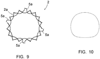
- FIGS 7 to 9 represent, from different angles, a second embodiment of the armature 2 of the prosthesis (the prosthetic valve is not shown), for the treatment of a mitral valve.
- the parts or elements already described, which are found in this second embodiment are designated by the same reference numerals.
- the atrial portion 2a is not conical in that it has a non-circular cross section but in the form of "D with rounded corners and edges" visible on the figure 9 and schematically represented on the figure 10 .
- this section has a rounded posterior portion, a slightly rounded anterior portion and two rounded lateral portions, these different portions being connected to each other by intermediate portions of smaller radius of curvature than they.
- the terms "posterior” and “anterior” above refer respectively to the portion of the prosthesis located on the posterior side of the mitral valve ring and on the anterior side of the same ring after implantation.
- the atrial portion 2a flares outwardly of the prosthesis, having an increasing section, from said annular portion 2i towards the end of this portion. atrial 2a opposite this annular portion 2i.
- the annular 2i and ventricular portions 2v have similar shapes to those of the prosthesis according to the first embodiment, except that the ventricular portion 2v is less closed at its end opposite the annular portion 2i, being truncated relative to that according to the first embodiment.
- each anchoring point 5a, 5v has a base portion connected to the portion 2a, 2v corresponding to the frame 2 and a free end portion which is bent relative to said base portion.
- This base portion is substantially rectilinear and protrudes from the portion 2a, 2v in a direction forming an angle of the order of 45 ° relative to the longitudinal axis of the frame (see particularly the figure 8 ); it has a length of the order of two to three times that of the free end portion. The latter is bent with respect to the base portion and is oriented in a substantially circumferential direction of the prosthesis.
- the anchoring points 5a, 5v are distributed in the following manner on the circumference of the armature 2: a point located on the zone of this armature located at the level of the anterior trigone after implantation, a tip located on the zone of the armature 2 located at the level of the posterior trine after implantation, a point located on the area of the armature 2 being, after implantation, at the anterior commissure of the mitral valve, a point situated on the zone of the armature 2 being, after implantation, at the level of the posterior commissure of the mitral valve, a point located on the zone of the armature 2 which is, after implantation, in the middle of the posterior ring of the mitral valve and a tip located on the area of the armature 2 located, after implantation, in the middle of the anterior ring of the mitral valve.
- an atrial anchoring point 5a is oriented towards the free end portion of an adjacent ventricular anchoring tip 5v, close in the circumferential direction but angularly offset by relative to this atrial anchoring point 5a; reciprocally, the free end portion of a ventricular anchoring point 5v is oriented towards the free end portion of an atrial anchor point 5a adjacent, close in the circumferential direction but offset angularly with respect to this ventricular anchoring point.
- FIG 8 it should be understood that, in this side view, the anterior portion of the prosthesis (that is, the one closest to the observer) is superimposed on the posterior portion of the prosthesis, the two central 5a atrial points appear close to each other on this figure 8 whereas they are located one on the anterior side of the prosthesis and the other on the posterior side of this prosthesis; the same is true of the two central 5v ventricular points, the one located furthest left on this figure 8 being associated with the rightmost central atrial tip 5a, and the leftmost atrial tip 5a being associated with the rightmost ventricular tip 5v.
- the invention thus provides a mitral or tricuspid heart valve prosthesis 1 having, with respect to homologous prostheses of the prior art, the decisive advantages of not hindering, when it is put in place, the functioning of the aortic valve and to present a low risk of migration, and thus obstruction of the ventricular ejection pathway.
- this prosthesis has a relatively easy to implement implementation, and has a shape perfectly adapted to that of the implantation site.
Landscapes
- Health & Medical Sciences (AREA)
- Engineering & Computer Science (AREA)
- Biomedical Technology (AREA)
- Cardiology (AREA)
- Oral & Maxillofacial Surgery (AREA)
- Transplantation (AREA)
- Heart & Thoracic Surgery (AREA)
- Vascular Medicine (AREA)
- Life Sciences & Earth Sciences (AREA)
- Animal Behavior & Ethology (AREA)
- General Health & Medical Sciences (AREA)
- Public Health (AREA)
- Veterinary Medicine (AREA)
- Prostheses (AREA)
Claims (16)
- Mitral- oder Trikuspidal-Herzklappenprothese (1), umfassend eine expandierbare röhrenförmige Armatur (2) mit einer Maschenstruktur und eine prothetische Klappe (3), die an dieser Armatur montiert ist, wobei die Armatur (2) einen Atrialbereich (2a), einen Ventrikularbereich (2v) und einen ringförmigen Bereich (2i) umfasst, der zwischen diesem Atrial- und dem Ventrikularbereich angeordnet ist;- wobei der Atrialbereich (2a) unter Aufweitung zur Außenseite der Prothese hin von dem ringförmigen Bereich (2i) zu dem Ende dieses Atrialbereichs hin verläuft, der diesem ringförmigen Bereich entgegengesetzt ist, und an der Seite des ringförmigen Bereichs (2i) auf wenigstens einem Teil seines Umfangs Verankerungsspitzen (5a) umfasst, die von seiner Außenoberfläche vorstehen; und- wobei der Ventrikularbereich (2v) eine im Wesentlichen kugelförmige oder eiförmige Gestalt aufweist und an der Seite des ringförmigen Bereichs (2i) auf wenigstens einem Teil seines Umfangs Verankerungsspitzen (5v) umfasst, die von seiner Außenoberfläche vorstehen,dadurch gekennzeichnet, dass:- der Ventrikularbereich (2v) eine große Einbuchtung (6) an einer Seite aufweist, die sich in der Länge von dem Ende dieses Ventrikularbereichs (2v), das dem ringförmigen Bereich (2i) entgegengesetzt ist, bis zu dem Teil (2vm) dieses Ventrikularbereichs (2v) erstreckt, das nahe dem ringförmigen Bereich (2i) ist, wobei sich diese Einbuchtung (6) über einen Sektor des Umfangs der Prothese (1) in der Größenordnung von 90 bis 140° erstreckt.
- Prothese (1) nach Anspruch 1, dadurch gekennzeichnet, dass sich die Einbuchtung über einen Sektor des Umfangs der Prothese in der Größenordnung von 120° erstreckt.
- Prothese (1) nach Anspruch 1 oder Anspruch 2, dadurch gekennzeichnet, dass die Verankerungsspitzen (5a, 5v) in der Form von gekrümmten Krallen sind, die sich ausgehend von ihren Basen in Richtung ihrer freien Spitzenenden zur Außenseite der Prothese hin entwickeln.
- Prothese (1) nach einem der Ansprüche 1 bis 3, dadurch gekennzeichnet, dass die Verankerungsspitzen (5a, 5v) auf ihrem gesamten Umfang vorhanden sind.
- Prothese (1) nach Anspruch 4, dadurch gekennzeichnet, dass die Verankerungsspitzen (5a, 5v) gleichmäßig über ihren gesamten Umfang verteilt sind.
- Prothese nach einem der Ansprüche 1 bis 5, dadurch gekennzeichnet, dass die Verankerungsspitzen (5a), die der Atrialbereich (2a) umfasst, gegenüber den Verankerungsspitzen (5v) angeordnet sind, die der Ventrikularbereich (2v) umfasst.
- Prothese (1) nach einem der Ansprüche 1 bis 6, dadurch gekennzeichnet, dass sie sechs Paare von Atrialverankerungsspitzen (5a) und von Ventrikularverankerungsspitzen (5v) umfasst.
- Prothese (1) nach Anspruch 1, dadurch gekennzeichnet, dass im Einsatzzustand der Prothese:- jede Verankerungsspitze (5a, 5v) einen im Wesentlichen geradlinigen Basisbereich aufweist, der von dem Bereich der Prothese entlang einer Richtung vorsteht, die einen Winkel von 35 bis 55° bezüglich der Längsachse der Prothese bildet, sowie einen freien Endbereich, der bezüglich des Basisbereichs abgewinkelt ist und sich im Wesentlichen entlang einer Umfangsrichtung der Prothese orientiert;- der freie Endbereich eine Atrialverankerungsspitze (5a) in Richtung des freien Endbereichs einer benachbarten Ventrikularverankerungsspitze (5v) orientiert ist, die in der Umfangsrichtung nahe ist, jedoch angular bezüglich dieser Atrialverankerungsspitze (5a) versetzt ist; und umgekehrt der freie Endbereich einer Ventrikularverankerungsspitze (5v) in Richtung des freien Endbereichs einer benachbarten Atrialverankerungsspitze (5a) orientiert ist, die in der Umfangsrichtung nahe ist, jedoch angular bezüglich dieser Ventrikularverankerungsspitze versetzt ist.
- Prothese (1) nach Anspruch 8, dadurch gekennzeichnet, dass jeder Basisbereich entlang einer Richtung vorsteht, die einen Winkel in der Größenordnung von 45° bezüglich der Längsachse der Prothese bildet.
- Prothese (1) nach Anspruch 8 oder Anspruch 9, dadurch gekennzeichnet, dass bei jeder Spitze die Länge des Basisbereichs in der Größenordnung von zwei bis drei Mal jener des freien Endbereichs ist.
- Prothese (1) nach einem der Ansprüche 8 bis 10, zur Behandlung einer Mitralklappe, dadurch gekennzeichnet, dass die Verankerungsspitzen (5a, 5v) auf folgende Weise über den Umfang der Armatur (2) der Prothese verteilt sind: eine Spitze, die an der Zone dieser Armatur angeordnet ist, die dazu ausgelegt ist, sich nach der Implantation im Bereich des anterioren Trigons zu befinden, eine Spitze, die an der Zone der Armatur (2) angeordnet ist, die dazu ausgelegt ist, sich nach der Implantation im Bereich des posterioren Trigons zu befinden, eine Spitze, die an der Zone der Armatur (2) angeordnet ist, die dazu ausgelegt ist, sich nach der Implantation im Bereich der anterioren Kommissur der Mitralklappe zu befinden, eine Spitze, die an der Zone der Armatur (2) angeordnet ist, die dazu ausgelegt ist, sich nach der Implantation im Bereich der posterioren Kommissur der Mitralklappe zu befinden, eine Spitze, die an der Zone der Armatur (2) angeordnet ist, die dazu ausgelegt ist, sich nach der Implantation in der Mitte des posterioren Rings der Mitralklappe zu befinden, sowie eine Spitze, die an der Zone der Armatur (2) angeordnet ist, die dazu ausgelegt ist, sich nach der Implantation in der Mitte des anterioren Rings der Mitralklappe zu befinden.
- Prothese (1) nach einem der Ansprüche 1 bis 11, dadurch gekennzeichnet, dass die Maschenstruktur der Armatur (2) im Bereich der Atrialbereiche (2a) und ringförmigen Bereichen (2i) sowie im Bereich des Teils des Ventrikularbereichs (2v), der die Verankerungsspitzen (5v) umfasst, rautenförmige Maschen umfasst, die an ihren Ecken miteinander verbunden sind.
- Prothese (1) nach Anspruch 12 in Kombination mit einem der Ansprüche 3 bis 7, dadurch gekennzeichnet, dass die Basen der Verankerungsspitzen (5a, 5v) mit den Bereichen der Maschen verbunden sind, die die entgegengesetzten Ecken dieser Maschen in der Atrial-Ventrikularrichtung der Prothese bilden, wobei diese Verankerungssitzen (5a, 5v) von diesen Maschenbereichen vorstehen.
- Prothese (1) nach einem der Ansprüche 1 bis 13, dadurch gekennzeichnet, dass die Maschenstruktur der Armatur (2) im Bereich des Teils des Ventrikularbereichs (2v) ohne Verankerungsspitzen (5v) wassertropfenförmige Maschen umfasst, wobei zwei benachbarte Maschen entgegengesetzt zueinander angeordnet sind.
- Prothese (1) nach einem der Ansprüche 1 bis 14, die dazu ausgelegt ist, eine Mitralklappe zu behandeln, dadurch gekennzeichnet, dass ihr Atrialbereich (2a) und ihr ringförmiger Bereich (2i) einen nicht kreisförmigen Querschnitt in Gestalt eines "D mit abgerundeten Ecken und Rändern" aufweisen.
- Prothese (1) nach einem der Ansprüche 1 bis 15, dadurch gekennzeichnet, dass ihr Atrialbereich (2a) eine dichte Wand umfasst, die ihre Maschen bedeckt.
Applications Claiming Priority (2)
| Application Number | Priority Date | Filing Date | Title |
|---|---|---|---|
| FR1454678A FR3021208B1 (fr) | 2014-05-23 | 2014-05-23 | Prothese de valve cardiaque mitrale ou tricuspide |
| PCT/IB2015/050498 WO2015177655A1 (fr) | 2014-05-23 | 2015-01-22 | Prothèse de valve cardiaque mitrale ou tricuspide |
Publications (2)
| Publication Number | Publication Date |
|---|---|
| EP3145448A1 EP3145448A1 (de) | 2017-03-29 |
| EP3145448B1 true EP3145448B1 (de) | 2018-05-16 |
Family
ID=51063725
Family Applications (1)
| Application Number | Title | Priority Date | Filing Date |
|---|---|---|---|
| EP15708282.7A Active EP3145448B1 (de) | 2014-05-23 | 2015-01-22 | Prothetische mitral- oder trikuspidalherzklappe |
Country Status (7)
| Country | Link |
|---|---|
| US (1) | US10925725B2 (de) |
| EP (1) | EP3145448B1 (de) |
| JP (1) | JP6551421B2 (de) |
| CN (1) | CN106456329B (de) |
| CA (1) | CA2949461C (de) |
| FR (1) | FR3021208B1 (de) |
| WO (1) | WO2015177655A1 (de) |
Cited By (15)
| Publication number | Priority date | Publication date | Assignee | Title |
|---|---|---|---|---|
| US10856984B2 (en) | 2017-08-25 | 2020-12-08 | Neovasc Tiara Inc. | Sequentially deployed transcatheter mitral valve prosthesis |
| US10940001B2 (en) | 2012-05-30 | 2021-03-09 | Neovasc Tiara Inc. | Methods and apparatus for loading a prosthesis onto a delivery system |
| US11311376B2 (en) | 2019-06-20 | 2022-04-26 | Neovase Tiara Inc. | Low profile prosthetic mitral valve |
| US11357622B2 (en) | 2016-01-29 | 2022-06-14 | Neovase Tiara Inc. | Prosthetic valve for avoiding obstruction of outflow |
| US11389291B2 (en) | 2013-04-04 | 2022-07-19 | Neovase Tiara Inc. | Methods and apparatus for delivering a prosthetic valve to a beating heart |
| US11413139B2 (en) | 2011-11-23 | 2022-08-16 | Neovasc Tiara Inc. | Sequentially deployed transcatheter mitral valve prosthesis |
| US11419720B2 (en) | 2010-05-05 | 2022-08-23 | Neovasc Tiara Inc. | Transcatheter mitral valve prosthesis |
| US11464631B2 (en) | 2016-11-21 | 2022-10-11 | Neovasc Tiara Inc. | Methods and systems for rapid retraction of a transcatheter heart valve delivery system |
| US11491006B2 (en) | 2019-04-10 | 2022-11-08 | Neovasc Tiara Inc. | Prosthetic valve with natural blood flow |
| US11497602B2 (en) | 2012-02-14 | 2022-11-15 | Neovasc Tiara Inc. | Methods and apparatus for engaging a valve prosthesis with tissue |
| US11602429B2 (en) | 2019-04-01 | 2023-03-14 | Neovasc Tiara Inc. | Controllably deployable prosthetic valve |
| US11737872B2 (en) | 2018-11-08 | 2023-08-29 | Neovasc Tiara Inc. | Ventricular deployment of a transcatheter mitral valve prosthesis |
| US11779742B2 (en) | 2019-05-20 | 2023-10-10 | Neovasc Tiara Inc. | Introducer with hemostasis mechanism |
| US11998447B2 (en) | 2019-03-08 | 2024-06-04 | Neovasc Tiara Inc. | Retrievable prosthesis delivery system |
| US12109111B2 (en) | 2015-12-15 | 2024-10-08 | Neovasc Tiara Inc. | Transseptal delivery system |
Families Citing this family (22)
| Publication number | Priority date | Publication date | Assignee | Title |
|---|---|---|---|---|
| US20090105813A1 (en) | 2007-10-17 | 2009-04-23 | Sean Chambers | Implantable valve device |
| US10653523B2 (en) | 2017-01-19 | 2020-05-19 | 4C Medical Technologies, Inc. | Systems, methods and devices for delivery systems, methods and devices for implanting prosthetic heart valves |
| US10561495B2 (en) | 2017-01-24 | 2020-02-18 | 4C Medical Technologies, Inc. | Systems, methods and devices for two-step delivery and implantation of prosthetic heart valve |
| WO2018145249A1 (zh) * | 2017-02-07 | 2018-08-16 | 上海甲悦医疗器械有限公司 | 用于治疗三尖瓣反流的装置及其植入方法 |
| US12029647B2 (en) | 2017-03-07 | 2024-07-09 | 4C Medical Technologies, Inc. | Systems, methods and devices for prosthetic heart valve with single valve leaflet |
| CN109009568B (zh) * | 2017-06-09 | 2023-10-31 | 上海微创心通医疗科技有限公司 | 二尖瓣瓣膜假体、三尖瓣瓣膜假体及其支架 |
| US12036113B2 (en) | 2017-06-14 | 2024-07-16 | 4C Medical Technologies, Inc. | Delivery of heart chamber prosthetic valve implant |
| CN109498213A (zh) * | 2017-09-14 | 2019-03-22 | 上海微创心通医疗科技有限公司 | 一种瓣膜支架和瓣膜假体 |
| US11857441B2 (en) | 2018-09-04 | 2024-01-02 | 4C Medical Technologies, Inc. | Stent loading device |
| US12544226B2 (en) | 2019-02-14 | 2026-02-10 | 4C Medical Technologies, Inc. | Hydrophilic skirt for paravalvular leak mitigation and fit and apposition optimization for prosthetic heart valve implants |
| US11452628B2 (en) | 2019-04-15 | 2022-09-27 | 4C Medical Technologies, Inc. | Loading systems for collapsible prosthetic heart valve devices and methods thereof |
| US11944536B2 (en) * | 2019-08-13 | 2024-04-02 | The Chinese University Of Hong Kong | Transcatheter self-expandable tricuspid valve replacement system |
| US12133797B2 (en) | 2020-01-31 | 2024-11-05 | 4C Medical Technologies, Inc. | Prosthetic heart valve delivery system: paddle attachment feature |
| US11931253B2 (en) | 2020-01-31 | 2024-03-19 | 4C Medical Technologies, Inc. | Prosthetic heart valve delivery system: ball-slide attachment |
| US12053375B2 (en) | 2020-03-05 | 2024-08-06 | 4C Medical Technologies, Inc. | Prosthetic mitral valve with improved atrial and/or annular apposition and paravalvular leakage mitigation |
| US11992403B2 (en) | 2020-03-06 | 2024-05-28 | 4C Medical Technologies, Inc. | Devices, systems and methods for improving recapture of prosthetic heart valve device with stent frame having valve support with inwardly stent cells |
| CN112107392B (zh) * | 2020-10-16 | 2025-07-25 | 上海纽脉医疗科技有限公司 | 一种人工心脏瓣膜支架及人工心脏瓣膜 |
| CN116138928A (zh) * | 2021-11-19 | 2023-05-23 | 鑫依医疗科技(北京)有限公司 | 一种降低左心室出流口的介入二尖瓣瓣膜 |
| CN116138927A (zh) * | 2021-11-19 | 2023-05-23 | 鑫依医疗科技(北京)有限公司 | 一种介入二尖瓣瓣膜 |
| WO2023133723A1 (zh) * | 2022-01-12 | 2023-07-20 | 金仕生物科技(常熟)有限公司 | 带有两侧爪的介入二尖瓣瓣架及介入二尖瓣 |
| US12594164B1 (en) | 2022-09-01 | 2026-04-07 | 4C Medical Technologies, Inc. | Prosthetic heart valve for natural blood flow |
| US20240366366A1 (en) | 2023-03-24 | 2024-11-07 | 4C Medical Technologies, Inc. | Implant delivery |
Family Cites Families (26)
| Publication number | Priority date | Publication date | Assignee | Title |
|---|---|---|---|---|
| US20040054403A1 (en) * | 2002-09-18 | 2004-03-18 | Israel Henry M | Angular orientation of a stent |
| JP4912395B2 (ja) * | 2005-05-24 | 2012-04-11 | エドワーズ ライフサイエンシーズ コーポレイション | 迅速配置式補綴用心臓弁 |
| DE602006019753D1 (de) * | 2005-09-01 | 2011-03-03 | Medtronic Vascular Inc | Verfahren und gerät zur behandlung von aneurysmen der a. thoracica |
| US7665466B2 (en) * | 2005-11-14 | 2010-02-23 | Occlutech Gmbh | Self-expanding medical occlusion device |
| KR101617052B1 (ko) * | 2008-04-23 | 2016-04-29 | 메드트로닉 인코포레이티드 | 스텐트 부착 심장 판막 장치 |
| ATE554731T1 (de) * | 2008-05-16 | 2012-05-15 | Sorin Biomedica Cardio Srl | Atraumatische prothetische herzklappenprothese |
| US9730790B2 (en) * | 2009-09-29 | 2017-08-15 | Edwards Lifesciences Cardiaq Llc | Replacement valve and method |
| WO2011072084A2 (en) * | 2009-12-08 | 2011-06-16 | Avalon Medical Ltd. | Device and system for transcatheter mitral valve replacement |
| US9480557B2 (en) * | 2010-03-25 | 2016-11-01 | Medtronic, Inc. | Stents for prosthetic heart valves |
| US9554897B2 (en) * | 2011-04-28 | 2017-01-31 | Neovasc Tiara Inc. | Methods and apparatus for engaging a valve prosthesis with tissue |
| CN103917194B (zh) * | 2011-09-12 | 2017-02-15 | 高品质生活简化股份公司 | 经导管瓣膜假体 |
| WO2013131069A1 (en) * | 2012-03-02 | 2013-09-06 | Mehr Medical Llc | Prostheses |
| ITTO20120372A1 (it) * | 2012-04-27 | 2013-10-28 | Marcio Scorsin | Protesi valvolare cardiaca monocuspide |
| US9072602B2 (en) * | 2012-11-14 | 2015-07-07 | Medtronic, Inc. | Transcatheter valve prosthesis having a variable shaped cross-section for preventing paravalvular leakage |
| US9089414B2 (en) * | 2013-03-22 | 2015-07-28 | Edwards Lifesciences Corporation | Device and method for increasing flow through the left atrial appendage |
| US9393111B2 (en) * | 2014-01-15 | 2016-07-19 | Sino Medical Sciences Technology Inc. | Device and method for mitral valve regurgitation treatment |
| WO2015081175A1 (en) * | 2013-11-26 | 2015-06-04 | Children's Medical Center Corporation | Expandable stent valve |
| US20170007392A1 (en) * | 2014-01-23 | 2017-01-12 | Biokyra Pesquisa E Desenvolvimento Ltda. | Endoprosthesis for endovascular treatment of thoracic-abdominal aortic aneurysms or dissections and endoprosthesis for endovascular treatment of abdominal aortic aneurysms or dissections which compromise the iliac arteries |
| EP3174502B1 (de) * | 2014-07-30 | 2022-04-06 | Cardiovalve Ltd | Vorrichtung zur implantation einer knickbaren klappenprothese |
| JP6363292B2 (ja) * | 2014-09-10 | 2018-07-25 | ザ クリーブランド クリニック ファウンデーションThe Cleveland ClinicFoundation | フレーム構造 |
| US20160120643A1 (en) * | 2014-11-05 | 2016-05-05 | Tara Kupumbati | Transcatheter cardiac valve prosthetic |
| KR20180023943A (ko) * | 2015-06-04 | 2018-03-07 | 에피곤 | 천연 첨판 파지 및 유지 기구를 갖는 방실 판막 스텐트 |
| WO2017081516A1 (fr) * | 2015-11-12 | 2017-05-18 | Valmy Holding | Prothese de valve cardiaque mitrale ou tricuspide |
| EP4309628A3 (de) * | 2015-12-03 | 2024-04-10 | Tendyne Holdings, Inc. | Rahmenmerkmale für mitralklappenprothesen |
| US20170360558A1 (en) * | 2016-06-16 | 2017-12-21 | Jianlu Ma | Method and design for a mitral regurgitation treatment device |
| WO2018026904A1 (en) * | 2016-08-03 | 2018-02-08 | Spence Paul A | Devices, systems and methods to improve placement and prevent heart block with percutaneous aortic valve replacement |
-
2014
- 2014-05-23 FR FR1454678A patent/FR3021208B1/fr active Active
-
2015
- 2015-01-22 CA CA2949461A patent/CA2949461C/fr active Active
- 2015-01-22 WO PCT/IB2015/050498 patent/WO2015177655A1/fr not_active Ceased
- 2015-01-22 EP EP15708282.7A patent/EP3145448B1/de active Active
- 2015-01-22 US US15/311,213 patent/US10925725B2/en active Active
- 2015-01-22 CN CN201580027245.6A patent/CN106456329B/zh active Active
- 2015-01-22 JP JP2016567259A patent/JP6551421B2/ja active Active
Non-Patent Citations (1)
| Title |
|---|
| None * |
Cited By (25)
| Publication number | Priority date | Publication date | Assignee | Title |
|---|---|---|---|---|
| US12611303B2 (en) | 2010-05-05 | 2026-04-28 | Neovasc Tiara Inc. | Transcatheter mitral valve prosthesis |
| US11419720B2 (en) | 2010-05-05 | 2022-08-23 | Neovasc Tiara Inc. | Transcatheter mitral valve prosthesis |
| US11413139B2 (en) | 2011-11-23 | 2022-08-16 | Neovasc Tiara Inc. | Sequentially deployed transcatheter mitral valve prosthesis |
| US12053369B2 (en) | 2011-11-23 | 2024-08-06 | Neovasc Tiara Inc. | Sequentially deployed transcatheter mitral valve prosthesis |
| US12138159B2 (en) | 2012-02-14 | 2024-11-12 | Neovasc Tiara Inc. | Methods and apparatus for engaging a valve prosthesis with tissue |
| US11497602B2 (en) | 2012-02-14 | 2022-11-15 | Neovasc Tiara Inc. | Methods and apparatus for engaging a valve prosthesis with tissue |
| US11617650B2 (en) | 2012-05-30 | 2023-04-04 | Neovasc Tiara Inc. | Methods and apparatus for loading a prosthesis onto a delivery system |
| US11389294B2 (en) | 2012-05-30 | 2022-07-19 | Neovasc Tiara Inc. | Methods and apparatus for loading a prosthesis onto a delivery system |
| US10940001B2 (en) | 2012-05-30 | 2021-03-09 | Neovasc Tiara Inc. | Methods and apparatus for loading a prosthesis onto a delivery system |
| US11389291B2 (en) | 2013-04-04 | 2022-07-19 | Neovase Tiara Inc. | Methods and apparatus for delivering a prosthetic valve to a beating heart |
| US12109111B2 (en) | 2015-12-15 | 2024-10-08 | Neovasc Tiara Inc. | Transseptal delivery system |
| US12193932B2 (en) | 2016-01-29 | 2025-01-14 | Neovasc Tiara Inc. | Prosthetic valve for avoiding obstruction of outflow |
| US11357622B2 (en) | 2016-01-29 | 2022-06-14 | Neovase Tiara Inc. | Prosthetic valve for avoiding obstruction of outflow |
| US11464631B2 (en) | 2016-11-21 | 2022-10-11 | Neovasc Tiara Inc. | Methods and systems for rapid retraction of a transcatheter heart valve delivery system |
| US12201524B2 (en) | 2016-11-21 | 2025-01-21 | Neovasc Tiara Inc. | Methods and systems for rapid retraction of a transcatheter heart valve delivery system |
| US11793640B2 (en) | 2017-08-25 | 2023-10-24 | Neovasc Tiara Inc. | Sequentially deployed transcatheter mitral valve prosthesis |
| US10856984B2 (en) | 2017-08-25 | 2020-12-08 | Neovasc Tiara Inc. | Sequentially deployed transcatheter mitral valve prosthesis |
| US11737872B2 (en) | 2018-11-08 | 2023-08-29 | Neovasc Tiara Inc. | Ventricular deployment of a transcatheter mitral valve prosthesis |
| US11998447B2 (en) | 2019-03-08 | 2024-06-04 | Neovasc Tiara Inc. | Retrievable prosthesis delivery system |
| US11602429B2 (en) | 2019-04-01 | 2023-03-14 | Neovasc Tiara Inc. | Controllably deployable prosthetic valve |
| US12036117B2 (en) | 2019-04-10 | 2024-07-16 | Neovasc Tiara Inc. | Prosthetic valve with natural blood flow |
| US11491006B2 (en) | 2019-04-10 | 2022-11-08 | Neovasc Tiara Inc. | Prosthetic valve with natural blood flow |
| US11779742B2 (en) | 2019-05-20 | 2023-10-10 | Neovasc Tiara Inc. | Introducer with hemostasis mechanism |
| US11931254B2 (en) | 2019-06-20 | 2024-03-19 | Neovasc Tiara Inc. | Low profile prosthetic mitral valve |
| US11311376B2 (en) | 2019-06-20 | 2022-04-26 | Neovase Tiara Inc. | Low profile prosthetic mitral valve |
Also Published As
| Publication number | Publication date |
|---|---|
| US20170100241A1 (en) | 2017-04-13 |
| CN106456329B (zh) | 2019-08-02 |
| JP2017526392A (ja) | 2017-09-14 |
| WO2015177655A1 (fr) | 2015-11-26 |
| EP3145448A1 (de) | 2017-03-29 |
| JP6551421B2 (ja) | 2019-07-31 |
| FR3021208A1 (fr) | 2015-11-27 |
| FR3021208B1 (fr) | 2021-03-12 |
| CA2949461A1 (fr) | 2015-11-26 |
| CA2949461C (fr) | 2022-04-05 |
| US10925725B2 (en) | 2021-02-23 |
| CN106456329A (zh) | 2017-02-22 |
Similar Documents
| Publication | Publication Date | Title |
|---|---|---|
| EP3145448B1 (de) | Prothetische mitral- oder trikuspidalherzklappe | |
| EP3373859B1 (de) | Prothetische mitral- oder trikuspidalherzklappe | |
| EP1411865B1 (de) | Anordnung zum einsetzen einer ventilprothese in ein körpergefäss | |
| EP2779943B1 (de) | Implantat zur positionierung in einem blutflussdurchgang und entsprechende behandlungsvorrichtung | |
| EP1786368B1 (de) | Ventilprothese | |
| CA2450935C (fr) | Ensemble permettant la mise en place d'une valve prothetique dans un conduit corporel | |
| EP1330213B1 (de) | Röhrenförmiger träger zum perkutanen einbringen einer herzklappenprothese | |
| EP3380042B2 (de) | Anordnung zum auswechseln der atrioventrikulären trikuspidalklappe | |
| EP2266504B1 (de) | Verfahren und Vorrichtung zum Einsetzen von Endoprothesen | |
| EP1791500A2 (de) | Austauschbare klappenprothese | |
| FR3027212A1 (fr) | Implant intervalvulaire pour valve mitrale | |
| FR3058632A1 (fr) | Dispositif de traitement d'une valve biologique avec organe de poussee de la valve | |
| US9597180B2 (en) | Transcatheter valve stent anchors | |
| FR3058631A1 (fr) | Implant de traitement d'une valve biologique | |
| EP2802292A1 (de) | Verankerungsvorrichtung für eine künstliche herzklappe | |
| FR3004638A1 (fr) | Implant, notamment destine a etre place dans une valve auriculo-ventriculaire cardiaque, comportant un systeme d'ecartement des bras proximaux | |
| FR2964855A1 (fr) | Implant destine a etre place dans un passage sanguin auriculo-ventriculaire | |
| JP2017508555A (ja) | 経カテーテル僧帽弁ステントフレーム | |
| FR3021209A1 (fr) | Prothese de valve cardiaque mitrale ou tricuspide | |
| FR3004334A1 (fr) | Prothese d'annuloplastie |
Legal Events
| Date | Code | Title | Description |
|---|---|---|---|
| STAA | Information on the status of an ep patent application or granted ep patent |
Free format text: STATUS: THE INTERNATIONAL PUBLICATION HAS BEEN MADE |
|
| PUAI | Public reference made under article 153(3) epc to a published international application that has entered the european phase |
Free format text: ORIGINAL CODE: 0009012 |
|
| STAA | Information on the status of an ep patent application or granted ep patent |
Free format text: STATUS: REQUEST FOR EXAMINATION WAS MADE |
|
| 17P | Request for examination filed |
Effective date: 20161130 |
|
| AK | Designated contracting states |
Kind code of ref document: A1 Designated state(s): AL AT BE BG CH CY CZ DE DK EE ES FI FR GB GR HR HU IE IS IT LI LT LU LV MC MK MT NL NO PL PT RO RS SE SI SK SM TR |
|
| AX | Request for extension of the european patent |
Extension state: BA ME |
|
| DAX | Request for extension of the european patent (deleted) | ||
| STAA | Information on the status of an ep patent application or granted ep patent |
Free format text: STATUS: EXAMINATION IS IN PROGRESS |
|
| 17Q | First examination report despatched |
Effective date: 20170927 |
|
| GRAP | Despatch of communication of intention to grant a patent |
Free format text: ORIGINAL CODE: EPIDOSNIGR1 |
|
| STAA | Information on the status of an ep patent application or granted ep patent |
Free format text: STATUS: GRANT OF PATENT IS INTENDED |
|
| INTG | Intention to grant announced |
Effective date: 20171222 |
|
| GRAS | Grant fee paid |
Free format text: ORIGINAL CODE: EPIDOSNIGR3 |
|
| GRAA | (expected) grant |
Free format text: ORIGINAL CODE: 0009210 |
|
| STAA | Information on the status of an ep patent application or granted ep patent |
Free format text: STATUS: THE PATENT HAS BEEN GRANTED |
|
| RIN1 | Information on inventor provided before grant (corrected) |
Inventor name: MODINE, THOMAS |
|
| AK | Designated contracting states |
Kind code of ref document: B1 Designated state(s): AL AT BE BG CH CY CZ DE DK EE ES FI FR GB GR HR HU IE IS IT LI LT LU LV MC MK MT NL NO PL PT RO RS SE SI SK SM TR |
|
| REG | Reference to a national code |
Ref country code: GB Ref legal event code: FG4D Free format text: NOT ENGLISH |
|
| REG | Reference to a national code |
Ref country code: CH Ref legal event code: EP |
|
| REG | Reference to a national code |
Ref country code: IE Ref legal event code: FG4D Free format text: LANGUAGE OF EP DOCUMENT: FRENCH |
|
| REG | Reference to a national code |
Ref country code: DE Ref legal event code: R096 Ref document number: 602015011151 Country of ref document: DE |
|
| REG | Reference to a national code |
Ref country code: AT Ref legal event code: REF Ref document number: 998881 Country of ref document: AT Kind code of ref document: T Effective date: 20180615 |
|
| REG | Reference to a national code |
Ref country code: NL Ref legal event code: MP Effective date: 20180516 |
|
| REG | Reference to a national code |
Ref country code: LT Ref legal event code: MG4D |
|
| PG25 | Lapsed in a contracting state [announced via postgrant information from national office to epo] |
Ref country code: NO Free format text: LAPSE BECAUSE OF FAILURE TO SUBMIT A TRANSLATION OF THE DESCRIPTION OR TO PAY THE FEE WITHIN THE PRESCRIBED TIME-LIMIT Effective date: 20180816 Ref country code: FI Free format text: LAPSE BECAUSE OF FAILURE TO SUBMIT A TRANSLATION OF THE DESCRIPTION OR TO PAY THE FEE WITHIN THE PRESCRIBED TIME-LIMIT Effective date: 20180516 Ref country code: BG Free format text: LAPSE BECAUSE OF FAILURE TO SUBMIT A TRANSLATION OF THE DESCRIPTION OR TO PAY THE FEE WITHIN THE PRESCRIBED TIME-LIMIT Effective date: 20180816 Ref country code: LT Free format text: LAPSE BECAUSE OF FAILURE TO SUBMIT A TRANSLATION OF THE DESCRIPTION OR TO PAY THE FEE WITHIN THE PRESCRIBED TIME-LIMIT Effective date: 20180516 Ref country code: ES Free format text: LAPSE BECAUSE OF FAILURE TO SUBMIT A TRANSLATION OF THE DESCRIPTION OR TO PAY THE FEE WITHIN THE PRESCRIBED TIME-LIMIT Effective date: 20180516 Ref country code: SE Free format text: LAPSE BECAUSE OF FAILURE TO SUBMIT A TRANSLATION OF THE DESCRIPTION OR TO PAY THE FEE WITHIN THE PRESCRIBED TIME-LIMIT Effective date: 20180516 |
|
| PG25 | Lapsed in a contracting state [announced via postgrant information from national office to epo] |
Ref country code: LV Free format text: LAPSE BECAUSE OF FAILURE TO SUBMIT A TRANSLATION OF THE DESCRIPTION OR TO PAY THE FEE WITHIN THE PRESCRIBED TIME-LIMIT Effective date: 20180516 Ref country code: HR Free format text: LAPSE BECAUSE OF FAILURE TO SUBMIT A TRANSLATION OF THE DESCRIPTION OR TO PAY THE FEE WITHIN THE PRESCRIBED TIME-LIMIT Effective date: 20180516 Ref country code: RS Free format text: LAPSE BECAUSE OF FAILURE TO SUBMIT A TRANSLATION OF THE DESCRIPTION OR TO PAY THE FEE WITHIN THE PRESCRIBED TIME-LIMIT Effective date: 20180516 Ref country code: GR Free format text: LAPSE BECAUSE OF FAILURE TO SUBMIT A TRANSLATION OF THE DESCRIPTION OR TO PAY THE FEE WITHIN THE PRESCRIBED TIME-LIMIT Effective date: 20180817 Ref country code: NL Free format text: LAPSE BECAUSE OF FAILURE TO SUBMIT A TRANSLATION OF THE DESCRIPTION OR TO PAY THE FEE WITHIN THE PRESCRIBED TIME-LIMIT Effective date: 20180516 |
|
| REG | Reference to a national code |
Ref country code: AT Ref legal event code: MK05 Ref document number: 998881 Country of ref document: AT Kind code of ref document: T Effective date: 20180516 |
|
| PG25 | Lapsed in a contracting state [announced via postgrant information from national office to epo] |
Ref country code: DK Free format text: LAPSE BECAUSE OF FAILURE TO SUBMIT A TRANSLATION OF THE DESCRIPTION OR TO PAY THE FEE WITHIN THE PRESCRIBED TIME-LIMIT Effective date: 20180516 Ref country code: PL Free format text: LAPSE BECAUSE OF FAILURE TO SUBMIT A TRANSLATION OF THE DESCRIPTION OR TO PAY THE FEE WITHIN THE PRESCRIBED TIME-LIMIT Effective date: 20180516 Ref country code: SK Free format text: LAPSE BECAUSE OF FAILURE TO SUBMIT A TRANSLATION OF THE DESCRIPTION OR TO PAY THE FEE WITHIN THE PRESCRIBED TIME-LIMIT Effective date: 20180516 Ref country code: CZ Free format text: LAPSE BECAUSE OF FAILURE TO SUBMIT A TRANSLATION OF THE DESCRIPTION OR TO PAY THE FEE WITHIN THE PRESCRIBED TIME-LIMIT Effective date: 20180516 Ref country code: RO Free format text: LAPSE BECAUSE OF FAILURE TO SUBMIT A TRANSLATION OF THE DESCRIPTION OR TO PAY THE FEE WITHIN THE PRESCRIBED TIME-LIMIT Effective date: 20180516 Ref country code: EE Free format text: LAPSE BECAUSE OF FAILURE TO SUBMIT A TRANSLATION OF THE DESCRIPTION OR TO PAY THE FEE WITHIN THE PRESCRIBED TIME-LIMIT Effective date: 20180516 Ref country code: AT Free format text: LAPSE BECAUSE OF FAILURE TO SUBMIT A TRANSLATION OF THE DESCRIPTION OR TO PAY THE FEE WITHIN THE PRESCRIBED TIME-LIMIT Effective date: 20180516 |
|
| REG | Reference to a national code |
Ref country code: DE Ref legal event code: R097 Ref document number: 602015011151 Country of ref document: DE |
|
| PG25 | Lapsed in a contracting state [announced via postgrant information from national office to epo] |
Ref country code: SM Free format text: LAPSE BECAUSE OF FAILURE TO SUBMIT A TRANSLATION OF THE DESCRIPTION OR TO PAY THE FEE WITHIN THE PRESCRIBED TIME-LIMIT Effective date: 20180516 |
|
| PLBE | No opposition filed within time limit |
Free format text: ORIGINAL CODE: 0009261 |
|
| STAA | Information on the status of an ep patent application or granted ep patent |
Free format text: STATUS: NO OPPOSITION FILED WITHIN TIME LIMIT |
|
| 26N | No opposition filed |
Effective date: 20190219 |
|
| PG25 | Lapsed in a contracting state [announced via postgrant information from national office to epo] |
Ref country code: SI Free format text: LAPSE BECAUSE OF FAILURE TO SUBMIT A TRANSLATION OF THE DESCRIPTION OR TO PAY THE FEE WITHIN THE PRESCRIBED TIME-LIMIT Effective date: 20180516 |
|
| PG25 | Lapsed in a contracting state [announced via postgrant information from national office to epo] |
Ref country code: MC Free format text: LAPSE BECAUSE OF FAILURE TO SUBMIT A TRANSLATION OF THE DESCRIPTION OR TO PAY THE FEE WITHIN THE PRESCRIBED TIME-LIMIT Effective date: 20180516 |
|
| REG | Reference to a national code |
Ref country code: CH Ref legal event code: PL |
|
| PG25 | Lapsed in a contracting state [announced via postgrant information from national office to epo] |
Ref country code: LU Free format text: LAPSE BECAUSE OF NON-PAYMENT OF DUE FEES Effective date: 20190122 |
|
| REG | Reference to a national code |
Ref country code: BE Ref legal event code: MM Effective date: 20190131 |
|
| REG | Reference to a national code |
Ref country code: IE Ref legal event code: MM4A |
|
| PG25 | Lapsed in a contracting state [announced via postgrant information from national office to epo] |
Ref country code: BE Free format text: LAPSE BECAUSE OF NON-PAYMENT OF DUE FEES Effective date: 20190131 Ref country code: AL Free format text: LAPSE BECAUSE OF FAILURE TO SUBMIT A TRANSLATION OF THE DESCRIPTION OR TO PAY THE FEE WITHIN THE PRESCRIBED TIME-LIMIT Effective date: 20180516 |
|
| PG25 | Lapsed in a contracting state [announced via postgrant information from national office to epo] |
Ref country code: LI Free format text: LAPSE BECAUSE OF NON-PAYMENT OF DUE FEES Effective date: 20190131 Ref country code: CH Free format text: LAPSE BECAUSE OF NON-PAYMENT OF DUE FEES Effective date: 20190131 |
|
| PG25 | Lapsed in a contracting state [announced via postgrant information from national office to epo] |
Ref country code: IE Free format text: LAPSE BECAUSE OF NON-PAYMENT OF DUE FEES Effective date: 20190122 |
|
| PG25 | Lapsed in a contracting state [announced via postgrant information from national office to epo] |
Ref country code: TR Free format text: LAPSE BECAUSE OF FAILURE TO SUBMIT A TRANSLATION OF THE DESCRIPTION OR TO PAY THE FEE WITHIN THE PRESCRIBED TIME-LIMIT Effective date: 20180516 |
|
| PG25 | Lapsed in a contracting state [announced via postgrant information from national office to epo] |
Ref country code: PT Free format text: LAPSE BECAUSE OF FAILURE TO SUBMIT A TRANSLATION OF THE DESCRIPTION OR TO PAY THE FEE WITHIN THE PRESCRIBED TIME-LIMIT Effective date: 20180917 Ref country code: MT Free format text: LAPSE BECAUSE OF FAILURE TO SUBMIT A TRANSLATION OF THE DESCRIPTION OR TO PAY THE FEE WITHIN THE PRESCRIBED TIME-LIMIT Effective date: 20180516 |
|
| PG25 | Lapsed in a contracting state [announced via postgrant information from national office to epo] |
Ref country code: CY Free format text: LAPSE BECAUSE OF FAILURE TO SUBMIT A TRANSLATION OF THE DESCRIPTION OR TO PAY THE FEE WITHIN THE PRESCRIBED TIME-LIMIT Effective date: 20180516 |
|
| PG25 | Lapsed in a contracting state [announced via postgrant information from national office to epo] |
Ref country code: IS Free format text: LAPSE BECAUSE OF FAILURE TO SUBMIT A TRANSLATION OF THE DESCRIPTION OR TO PAY THE FEE WITHIN THE PRESCRIBED TIME-LIMIT Effective date: 20180916 |
|
| PG25 | Lapsed in a contracting state [announced via postgrant information from national office to epo] |
Ref country code: HU Free format text: LAPSE BECAUSE OF FAILURE TO SUBMIT A TRANSLATION OF THE DESCRIPTION OR TO PAY THE FEE WITHIN THE PRESCRIBED TIME-LIMIT; INVALID AB INITIO Effective date: 20150122 |
|
| PG25 | Lapsed in a contracting state [announced via postgrant information from national office to epo] |
Ref country code: MK Free format text: LAPSE BECAUSE OF FAILURE TO SUBMIT A TRANSLATION OF THE DESCRIPTION OR TO PAY THE FEE WITHIN THE PRESCRIBED TIME-LIMIT Effective date: 20180516 |
|
| P01 | Opt-out of the competence of the unified patent court (upc) registered |
Effective date: 20230515 |
|
| PGFP | Annual fee paid to national office [announced via postgrant information from national office to epo] |
Ref country code: GB Payment date: 20260123 Year of fee payment: 12 |
|
| PGFP | Annual fee paid to national office [announced via postgrant information from national office to epo] |
Ref country code: DE Payment date: 20260121 Year of fee payment: 12 |
|
| PGFP | Annual fee paid to national office [announced via postgrant information from national office to epo] |
Ref country code: IT Payment date: 20260126 Year of fee payment: 12 |
|
| PGFP | Annual fee paid to national office [announced via postgrant information from national office to epo] |
Ref country code: FR Payment date: 20260129 Year of fee payment: 12 |