EP3145601B1 - Appareil permettant d'enfiler des palmes - Google Patents
Appareil permettant d'enfiler des palmes Download PDFInfo
- Publication number
- EP3145601B1 EP3145601B1 EP15730269.6A EP15730269A EP3145601B1 EP 3145601 B1 EP3145601 B1 EP 3145601B1 EP 15730269 A EP15730269 A EP 15730269A EP 3145601 B1 EP3145601 B1 EP 3145601B1
- Authority
- EP
- European Patent Office
- Prior art keywords
- flipper
- retaining means
- shoe
- foot
- seating
- Prior art date
- Legal status (The legal status is an assumption and is not a legal conclusion. Google has not performed a legal analysis and makes no representation as to the accuracy of the status listed.)
- Active
Links
Images

Classifications
-
- A—HUMAN NECESSITIES
- A63—SPORTS; GAMES; AMUSEMENTS
- A63B—APPARATUS FOR PHYSICAL TRAINING, GYMNASTICS, SWIMMING, CLIMBING, OR FENCING; BALL GAMES; TRAINING EQUIPMENT
- A63B31/00—Swimming aids
- A63B31/08—Swim fins, flippers or other swimming aids held by, or attachable to, the hands, arms, feet or legs
- A63B31/10—Swim fins, flippers or other swimming aids held by, or attachable to, the hands, arms, feet or legs held by, or attachable to, the hands or feet
- A63B31/11—Swim fins, flippers or other swimming aids held by, or attachable to, the hands, arms, feet or legs held by, or attachable to, the hands or feet attachable only to the feet
-
- A—HUMAN NECESSITIES
- A47—FURNITURE; DOMESTIC ARTICLES OR APPLIANCES; COFFEE MILLS; SPICE MILLS; SUCTION CLEANERS IN GENERAL
- A47G—HOUSEHOLD OR TABLE EQUIPMENT
- A47G25/00—Household implements used in connection with wearing apparel; Dress, hat or umbrella holders
- A47G25/80—Devices for putting-on or removing boots or shoes, e.g. boot-hooks, boot-jacks
-
- A—HUMAN NECESSITIES
- A47—FURNITURE; DOMESTIC ARTICLES OR APPLIANCES; COFFEE MILLS; SPICE MILLS; SUCTION CLEANERS IN GENERAL
- A47G—HOUSEHOLD OR TABLE EQUIPMENT
- A47G25/00—Household implements used in connection with wearing apparel; Dress, hat or umbrella holders
- A47G25/80—Devices for putting-on or removing boots or shoes, e.g. boot-hooks, boot-jacks
- A47G25/82—Shoe horns
-
- A—HUMAN NECESSITIES
- A47—FURNITURE; DOMESTIC ARTICLES OR APPLIANCES; COFFEE MILLS; SPICE MILLS; SUCTION CLEANERS IN GENERAL
- A47G—HOUSEHOLD OR TABLE EQUIPMENT
- A47G25/00—Household implements used in connection with wearing apparel; Dress, hat or umbrella holders
- A47G25/90—Devices for domestic use for assisting in putting-on or pulling-off clothing, e.g. stockings or trousers
Definitions
- the invention relates to an apparatus for putting on flippers.
- flippers relates to all footwear which can be used for various sporting activities, such as underwater diving, swimming and so on.
- a possible application of the invention relates to flippers, to which reference will be made by way of example below.
- Flippers for swimming are generally provided with a large propulsion portion due to the presence of a flexible blade (flipper).
- swimming flippers have, in addition to the flexible blade, a seating in the form of a shoe integral with the blade itself and enabling insertion of the foot of person wearing the flipper, for example the swimmer or underwater swimmer.
- the shoe in particular comprises a rear part which does not contain the foot, therefore open at the heel, for introducing the foot in the housing thereof.
- this type of flipper has a strap or elastic belt hooked laterally of the flipper shoe.
- the underwater swimmer In order to fit the flippers and fasten them to the underwater swimmer's foot, using elastic straps or other known fastening means, the underwater swimmer has to count on the assistance of another person or has to crouch with movements that are laborious and involve bending. These movements are conditioned, for most users, by their own weight and the weight of the equipment being carried, as the user has to stand on a single leg for the time needed to put on each flipper, and this generates significant difficulty.
- the first static position is lowered and leaves the opening of the shoe of the flipper free, keeping a strap of the connection between the shoe and the apparatus tautened, and the second static position is raised for keeping the foot inside the shoe.
- the first stable position is realised by placing the fulcrum of rotation of the apparatus in a defined position of the shoe where the strap applies neither force nor momentum at any time about the anchoring pin, the lever arm being reduced substantially to zero, and therefore even if the strap is kept in tension, the apparatus remains in equilibrium in the first position.
- a drawback of a solution of this type is that during use in underwater diving or swimming, the apparatus might pass from the second retaining position of the foot to the first position in an undesired and uncontrolled way, causing the loss of the entire flipper, as the strap is not always tensioned towards the second position.
- the momentum reduces progressively up to zero, reaching zero when it is in the first position.
- a further disadvantage is that the apparatus might pass beyond the pin anchoring element and therefore become positioned beneath the flipper in a position opposite the first position, making correct repositioning thereof extremely difficult, which could occur only with the person making very problematic bending movements, with the risks as set out above.
- a disadvantage of this technique is that it is necessary for the user to act with the hands, in precarious equilibrium, for inserting the tongue in the clip, and this action has features of great uncertainty, difficulty and high instability, being extremely risky for the reasons set out in the foregoing.
- An aim of the invention is to obviate the drawbacks of the prior art described above.
- a further aim of the invention is to provide an apparatus for fastening the foot of a person into an item of footwear, such as a swimming flipper.
- a further aim is to provide an apparatus for fastening the foot of a person in an item of footwear which can be easily fixed without the use of the person's hands and be easily released with minimum force, all done in conditions of maximum safety.
- a further aim of the invention is to provide an apparatus which can be used in flippers of the conventional type without the need for structural modifications to the shoe of the flipper or to a part thereof.
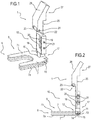
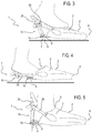
- reference numeral 1 denotes a machine for putting on flippers 2, such as, for example, flippers for underwater swimmers, defined in their entirety as users, to which explicit reference will be made without losing in terms of general applicability.
- flippers will be used to refer to all footwear which can be used for various sporting activities such as underwater immersion, swimming and so on.
- the flipper 2 to which reference is made herein comprises a part for inserting the underwater swimmer's foot which will be referred-to as a shoe 3, and a part that comprises a blade 4 which is constituted for generating a large portion of propulsion.
- the blade 4 has a flexible laminar shape, constituting the flipper proper, and is illustrated only partially in figures from 3 to 5 being interrupted by a saw-toothed line.
- the shoe 3 of the flipper 2 is without a rear containing part, that is to say, a rear part open at the position of the user's heel, so as to enable introduction of the foot in a housing 5, constituting the seating for the foot.
- the apparatus 1 comprises retaining means 10 of the foot of the underwater swimmer in the correct position inside the housing 5 of the flipper 2 itself and comprises removable attaching means 9 to the flipper 2.
- the retaining means 10 and the attaching means 9 are mechanically connected to one another.
- the attaching means 9 to the flipper 2 comprise a pair of jaws 6, which in a preferred embodiment are each made with a substantially U-shaped plate 7.
- the two plates 7 are facing each other and spaced by an amount such as to enable insertion of a base or sole 8 of the shoe 3 of the flipper 2.
- the distance between the two plates 7 is therefore approximately the thickness of the material which forms the sole 8.
- the attaching means 9 are therefore removably associable way to a portion of the base 8 of the shoe 3.
- the sole 8 of the shoe 3 is interposed between a lower plate 7a, positioned below the sole 8 of the flipper 2, and an upper plate 7b, positioned above the sole 8 and partly inside the housing 5 (see figure 5 ).
- the upper plate 7b is preferably made of an elastic material. This means that, following a slight deformation thereof, the sole 8 can be gripped by the jaws 6 so as to be retained, in such a way as to enable connection of the apparatus 1 to the flipper 2 during use thereof.
- the distance between the two plates 7 is defined by the thickness of a raised part 11 present in the upper plate 7b at an end 12 thereof, which, in use, is positioned externally of the shoe 3 and is positioned at the base of above-mentioned U-shape.
- This thickness of the raised part 11 can depend on the thickness of the sole 8.
- the elasticity of the material of the plate 7b can however be sufficient to cover different thickness measurements, so as to guarantee a broad versatility of the apparatus, irrespective of the flipper 2 to which it is applied.
- a through-hole 13 having an axis parallel to the lie plane defined by the plates 7.
- a spindle 14 is present internally of the hole.
- the spindle 14 in the hole 13 constitutes a hinge 15 in which the retaining means 10 are pivoted.
- the retaining means 10 and the attaching means 9 are mechanically reciprocally pivoted.
- the retaining means 10 are partly located in the seat of a recess 16 made in the plates 7 and have a passage which is able to partly house the spindle 14, which passes through a through-hole.
- the spindle 14 can be rigidly connected to the plates 7 and the retaining means 10 can be free to rotate about the spindle 14.
- the spindle 14 can be rigidly connected to the retaining means 10 and the plates 7 free to rotate about it.
- the retaining means 10 of the heel of the foot comprise a structure which has various characteristics.
- the retaining means 10 comprise a first end 17 that engages in the recess 16.
- An opposing zone 18 to the heel is present in proximity of the first end 17, which opposing zone 18 in turn comprises a slot 19 fashioned in the solid body of the heel and having an anatomical shape with respect to the heel.
- This slot 19 constitutes a supporting seat of the heel when the apparatus is in use.
- rollers 20 are located on the bottom of the slot 19, which rollers 20 are mounted rotatably about two spindles 21 blocked in the structural part of the retaining means 10.
- the rollers 20 may be in a greater number than two but they might also be only one in number, without thereby limiting the realising of further preferred embodiments of the invention which are not illustrated.
- a step 22 is present which constitutes a stop and abutment element for the heel, in such a way that accidental exit the foot is not possible, when, in use, the foot is fitted inside the shoe 3.
- At least a roller 23 is mounted in proximity of the step 22, which roller 23 is mounted in a similar way to the rollers 20 by means of a spindle 24.
- the roller 23 has a portion of the cylindrical surface thereof exiting from the step 22.
- rollers 20 also have a surface part of the cylindrical surface exiting from the slot 19.
- the presence thereof constitutes a facilitation for the sliding of the foot during insertion in the shoe 3, in particular when the foot of the underwater swimmer is covered by a suitable footwear for the immersions, for example a boot.
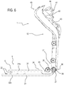
- the retaining means 10, on the side opposite the roller 23 and facing the roller 23, comprise a seating 25 for containing an elastic strap 26 which forms part of the flipper 2 (see figures 3 and 5 ).
- the strap 26 can be housed in the seating 25 only by overcoming the action of the elastic force thereof.
- the strap 26 can also be housed in the seating 25 and rigidly engaged thereto by means of a screw clamp of known type and not illustrated.
- the retaining means 10 comprise a second upper end 27, opposite the first end 17, which extends slopingly so as to facilitate rotation about the hinge 15, by means of a sloping surface 28.
- This rotation enables opening the housing 5 and inserting the foot inside it, as shown in the sequence of figures from 3 to 5.
- the foot can therefore slide first on the roller 23 and, having passed beyond the step 22, slide on the rollers 20 reaching the definitive position simply and correctly, without the user having to use either his own hands or enlist the help of other persons.
- the hinge 15 is located at a height equal to the level of the sole 8 of the shoe 3 and the seating 25 which contains the elastic strap 26 in a position proximal to the end 27, it will be impossible for a zero momentum to be reached and the elastic strap 26 is capable of applying a momentum which guarantees that the retaining means 10 secure and retain the foot inside the shoe and therefore retain the flipper in the correct position during the entire time of use thereof.
- the apparatus 1 comprises retaining means 10 of the underwater swimmer's foot in the correct position inside the housing 5 of the flipper 2, and comprises removable attaching means 9 to the flipper 2.
- the retaining means 10 and the attaching means 9 are mechanically connected to one another.
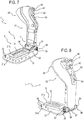
- the attaching means 9 of the flipper 2 comprise a pair of jaws 6, which in the second embodiment are each realised with a substantially ring-shaped plate 31.
- the two plates 31 face each other and are spaced by a dimension such as to reciprocally enable the entry thereof of a base or sole 8 of the shoe 3 of the flipper 2.
- the distance between the two plates 31 is therefore constituted by the thickness of the material which forms the sole 8.
- the attaching means 9 are therefore removably associable to a portion of the base 8 of the shoe 3.
- the sole 8 of the shoe 3 is interposed between a lower plate 31a, positioned beneath the sole 8 of the flipper 2, and an upper plate 31b, positioned above the sole 8 and partly inside the housing 5.
- both the lower plate 31a and the upper plate 31b comprise substantially wedge-shaped projections 32 in order to enable a better anchoring to the sole 8 of the flipper 2 and therefore to enable secure connection of the apparatus 1 to the flipper 2 during use thereof.
- the distance between the two plates 31 is defined by the thickness of a raised part 33 present in the upper plate 31b at an end 34 thereof, which, in use, is positioned externally of the shoe 3. This thickness of the raised part 33 can depend on the thickness of the sole 8.
- a through-hole 36 having an axis parallel to the lie plane defined by the plates 31.
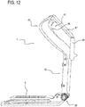
- a spindle is internally present in the hole 36, of a similar type to the spindle of the first embodiment and denoted in figure 2 by reference numeral 14.
- the spindle in the hole 36 constitutes a hinge 37 in which the retaining means 10 are pivoted.
- the fulcrum constituted by the hinge 37, has at least a blocking element 38.
- the blocking element 38 can be located at least on one side or, preferably, on both sides of the hinge 37.
- the blocking element 38 can be made in various ways, for example by an enmeshing of two opposite front couplings, which by means of a screw 39 are angularly connected to one another and do not enable reciprocal distancing of the two plates 31a and 31b, when, in use, the blocking element 38 is clamped by the screw 39.
- the strap 26 can be housed in a seating 41 which comprises a slide 42 able to slide in a guide 43.
- the strap 26 can also be housed in the seating 41 and be rigidly engaged on the slide 42 through at least an opening, for example a hole 44 of known type, internally of which the strap 26 is inserted.
- the slide 42 can slide from a high position, when the retaining means 10 are in retaining position, to a lower position, when the retaining means 10 are in laid-out position, for allowing the insertion of the flipper 2.
- the slide 42 is illustrated in raised position in figures 6 to 11 , while it is not illustrated in the lower position, which in any case corresponds to the position the slide can reach by sliding in the guide 43.
- This lower position is opposite the raised position with respect to the guide 43.
- the slide 42 can also be extracted from the guide 43 by removing a stop 40 arranged inferiorly of the guide 43 itself.
- This stop 40 is movable between a blocking position (illustrated in figure 8 ) and an open position (not illustrated). In particular the stop 40 is movable by a angular rotational movement.
- the second embodiment there is a further alternative, independent of the alternative of blocking the plates 31 and the slide 42, that relates to the retaining means 10.
- the second upper end 27 denoted by reference numeral 45 (in figures 6 to 11 ).
- the second upper end 45 is opposite the first end 17, which in this embodiment extends inclined on the opposite side with respect to the inclination of the first embodiment, so as to facilitate, in use, the rotation about the hinge 15 or 37.
- the second end 45 has a substantially U-shaped cross-section so as to have a anatomical shape for adapting better to a shape of the user's foot.
- systems for adjusting the height of the raised part 33 or other dimensions can be included, so as to adjust the regulations as a function of the size of the footwear and therefore of the shoe 3 of the flipper 2.
- the seating 41 of the strap 26 comprises a slot 46.
- the slot 46 is partly delimited by an abutment 47 joined to the second end 45 of the retaining means 10.
- the slot 46 is further delimited by a closing element 48.
- the closing element 48 can preferably be made of an elastically deformable material to allow opening of the slot 46 in order to introduce the strap 26, and for allowing the elastic closing of the same slot 46.
- the closing element 48 may be made of a rigid material, but movable between a closed position of the slot 46 and an open position for allowing the insertion of the strap 26. In this way, during use, the strap is free to move internally of the slot in steps of introducing the foot into the shoe 3, in a way similar to the one described with reference to figures from 3 to 5 and 9 to 11.
- An advantage of the embodiments that comprise a seating 41 is that the strap 26 is movable either along the guide 43 or in the slot 46.
- the possibility of this movement of the strap 26 causes the need for a smaller effort as the strap 26, which elastic, is subjected to traction by the user's foot during the step of introducing the foot inside the opening 5 of the shoe 3 of the flipper 2. This operation is therefore made easier and more comfortable.
Landscapes
- Health & Medical Sciences (AREA)
- General Health & Medical Sciences (AREA)
- Physical Education & Sports Medicine (AREA)
- Footwear And Its Accessory, Manufacturing Method And Apparatuses (AREA)
Claims (11)
- Appareil permettant d'enfiler une palme (2) comprenant des moyens de retenue (10) servant à retenir un pied d'un utilisateur à l'intérieur d'une chaussure (3) de la palme (2) et des moyens de fixation amovibles (9) se fixant à la chaussure ;
les moyens de fixation amovibles (9) pouvant être associés à une partie d'une semelle (8) de la chaussure (3) ;
caractérisé en ce que les moyens de retenue (10) sont mécaniquement reliés et montés pivotants aux moyens de fixation amovibles (9). - Appareil selon la revendication 1, caractérisé en ce que les moyens de fixation amovibles (9) comprennent une paire de mâchoires (6), chacune constituée d'une plaque (7 ; 31), de préférence une plaque en forme de « U » ou ayant substantiellement une forme annulaire.
- Appareil selon la revendication 1 ou 2, caractérisé en ce que les moyens de retenue (10) sont au moins en partie situés dans un renfoncement de réception (16) réalisé dans les plaques (7 ; 31) au moyen d'une charnière (15 ; 37) située à proximité d'une première extrémité (17), les moyens de retenue (10) étant ainsi montés pivotants et libres pour pivoter par rapport aux moyens de fixation (9).
- Appareil selon l'une quelconque des revendications de 1 à 3, caractérisé en ce que les moyens de retenue (10) d'un talon d'utilisateur comprennent une zone (18) opposée au talon du pied de l'utilisateur, la zone (18) comprenant une fente (19) ayant une forme anatomique pour le talon et constituant un emplacement de support du talon.
- Appareil selon la revendication 4, caractérisé en ce qu'au moins un rouleau (20) est situé sur un fond de la fente (19), ledit au moins un rouleau (20) étant monté en rotation sur une broche (21) bloquée dans la structure des moyens de retenue (10).
- Appareil selon l'une quelconque des revendications de 1 à 5, caractérisé en ce que à proximité de la fente (19) sur le côté opposé à la charnière (15), se trouve une saillie (22) constituant un élément d'arrêt et de buté pour le talon du pied de l'utilisateur.
- Appareil selon l'une quelconque des revendications de 1 à 6, caractérisé en ce que les moyens de retenue (10) comprennent un emplacement (25 ; 41) servant à contenir une bande élastique (26) faisant partie de la palme (2).
- Appareil selon l'une quelconque des revendications de 1 à 7, caractérisé en ce que les moyens de retenue (10) comprennent une seconde extrémité supérieure (27 ; 45), opposée à la première extrémité (17), qui se prolonge en pente inclinée de manière à faciliter la rotation autour de la charnière (15 ; 37) à travers une action de poussée appliquée par un pied sur une surface en pente (28).
- Appareil selon l'une quelconque des revendications de 3 à 8, caractérisé en ce que la charnière (15 ; 37) est située à la même hauteur qu'une position de la semelle (8) de la chaussure (3) et l'emplacement (25 ; 41) est dans une position proximale par rapport à la seconde extrémité (27 ; 45).
- Appareil selon la revendication 7, caractérisé en ce que l'emplacement (41), servant à contenir une bande élastique (26) faisant partie de la palme (2), comprend un coulisseau (42), pouvant coulisser dans un guide (43), ou l'emplacement (41) comprend une fente (46).
- Appareil selon l'une quelconque des revendications de 1 à 10, caractérisé en ce qu'un point d'appui constitué par la charnière (37) comporte au moins un élément de blocage (38).
Applications Claiming Priority (2)
| Application Number | Priority Date | Filing Date | Title |
|---|---|---|---|
| ITBO20140293 | 2014-05-19 | ||
| PCT/IB2015/053588 WO2015177695A1 (fr) | 2014-05-19 | 2015-05-15 | Appareil permettant d'enfiler des palmes |
Publications (2)
| Publication Number | Publication Date |
|---|---|
| EP3145601A1 EP3145601A1 (fr) | 2017-03-29 |
| EP3145601B1 true EP3145601B1 (fr) | 2019-03-20 |
Family
ID=51229967
Family Applications (1)
| Application Number | Title | Priority Date | Filing Date |
|---|---|---|---|
| EP15730269.6A Active EP3145601B1 (fr) | 2014-05-19 | 2015-05-15 | Appareil permettant d'enfiler des palmes |
Country Status (3)
| Country | Link |
|---|---|
| US (1) | US10058737B2 (fr) |
| EP (1) | EP3145601B1 (fr) |
| WO (1) | WO2015177695A1 (fr) |
Families Citing this family (7)
| Publication number | Priority date | Publication date | Assignee | Title |
|---|---|---|---|---|
| US10058737B2 (en) * | 2014-05-19 | 2018-08-28 | Paolo PIUMATTI | Apparatus for wearing fins |
| IT201600121316A1 (it) | 2016-11-30 | 2018-05-30 | Paolo Piumatti | Apparecchiatura per indossare pinne. |
| CN108295439A (zh) * | 2018-02-25 | 2018-07-20 | 宁波市晶杰国际物流有限公司 | 一种打枪式游泳穿戴设备 |
| CN108310730A (zh) * | 2018-02-25 | 2018-07-24 | 宁波市晶杰国际物流有限公司 | 打枪式穿戴设备 |
| CN108273245A (zh) * | 2018-02-25 | 2018-07-13 | 宁波市晶杰国际物流有限公司 | 一种游泳式穿戴设备 |
| RU2725049C1 (ru) * | 2020-02-26 | 2020-06-29 | Николай Гавриилович Кузьмин | Устройство для надевания защитных бахил |
| EP4382003A1 (fr) * | 2022-12-05 | 2024-06-12 | Dan-Rehab A/S | Procédé et support de rouleau pour aider les personnes à s'habiller |
Family Cites Families (15)
| Publication number | Priority date | Publication date | Assignee | Title |
|---|---|---|---|---|
| US2446777A (en) * | 1947-01-13 | 1948-08-10 | Frederick C Menenko | Shoehorn |
| US2828057A (en) * | 1956-07-16 | 1958-03-25 | Maclauchlan William | Device for putting on stockings |
| US3012702A (en) * | 1959-05-15 | 1961-12-12 | Vliet Leendert Christinus Der | Shoe horn |
| US3178738A (en) * | 1961-11-16 | 1965-04-20 | Everett A Brunner | Convertible swim fin |
| JPH0530448Y2 (fr) | 1986-11-12 | 1993-08-04 | ||
| US5083954A (en) * | 1990-01-19 | 1992-01-28 | Jacobs Edward R | Swim fin retainer |
| US5282327A (en) * | 1993-02-16 | 1994-02-01 | Ogle Estel E | Pivotal heel for footwear |
| ITGE940079A1 (it) | 1994-06-16 | 1995-12-16 | Htm Sport Spa | Pinna da nuoto munita di fibbia per l'agganciamento del cinghiolo a |
| FR2744639B1 (fr) | 1996-02-12 | 2000-09-15 | Dessault Danielle | Palme de natation a pointure variable |
| GB9719089D0 (en) | 1997-09-10 | 1997-11-12 | Scott Edward | Apparatus for fastening open heel footwear,including swimming fins |
| US5806729A (en) * | 1997-09-16 | 1998-09-15 | Ramon; Juan C. | Collapsible bootjack for putting on and removing boots |
| US7140937B2 (en) * | 2005-04-19 | 2006-11-28 | Ron Cadorette | Swim fin with detachable blade |
| FR2926999B1 (fr) * | 2008-01-31 | 2010-07-30 | Decathlon Sa | Palme de natation |
| US10058737B2 (en) * | 2014-05-19 | 2018-08-28 | Paolo PIUMATTI | Apparatus for wearing fins |
| US9332869B1 (en) * | 2015-09-29 | 2016-05-10 | Arthur J Beaudette | Shoe and orthosis donning aid |
-
2015
- 2015-05-15 US US15/311,204 patent/US10058737B2/en active Active
- 2015-05-15 EP EP15730269.6A patent/EP3145601B1/fr active Active
- 2015-05-15 WO PCT/IB2015/053588 patent/WO2015177695A1/fr not_active Ceased
Non-Patent Citations (1)
| Title |
|---|
| None * |
Also Published As
| Publication number | Publication date |
|---|---|
| US10058737B2 (en) | 2018-08-28 |
| WO2015177695A1 (fr) | 2015-11-26 |
| US20170095698A1 (en) | 2017-04-06 |
| EP3145601A1 (fr) | 2017-03-29 |
Similar Documents
| Publication | Publication Date | Title |
|---|---|---|
| EP3145601B1 (fr) | Appareil permettant d'enfiler des palmes | |
| US6290559B1 (en) | Apparatus for fastening open heel footwear, including swimming fins | |
| US5609347A (en) | Snowboard bindings with release apparatus | |
| AU2016266027B2 (en) | Continuous weave quick adjust harness backplate system | |
| US3410568A (en) | Tension adjustable releasable ski binding | |
| EP3165262A1 (fr) | Fixation de planche à neige et dispositif d'arrêt pour fixations de planche à neige | |
| EP3171949B1 (fr) | Appareil de transport pour équipement de ski | |
| US4461104A (en) | Removable walking attachment for ski boots | |
| US3506279A (en) | Equipment for achieving runs on all types of snow-covered ground | |
| NO159347B (no) | Skistav-par med en sittestroppanordning. | |
| WO2008087589A1 (fr) | Palme de natation et chaussure pour celle-ci | |
| ES2774907T3 (es) | Hebilla para casco | |
| EP3548151B1 (fr) | Appareil de port de palmes | |
| CN101559277B (zh) | 脚蹼 | |
| CN209967617U (zh) | 一种可调式滑雪板固定器 | |
| FR2656227A1 (fr) | Fixation a plaque tournante pour surf des neiges. | |
| US3557397A (en) | Swimming device | |
| US9296452B2 (en) | Removable diving weight | |
| EP2201988A1 (fr) | Dispositif pour le transport du matériel de glisse | |
| US10131411B1 (en) | Arm rescue device | |
| FR2504810A1 (fr) | Ensemble permettant de marcher sur l'eau | |
| JPH03211Y2 (fr) | ||
| KR20220089758A (ko) | 탈착 가능한 의자가 구비된 패들보드 | |
| FR3164631A1 (fr) | Dispositif pour l’apprentissage de sports de glisse | |
| JP2017192544A (ja) | スキー又はスノーボードの滑走指導補助具 |
Legal Events
| Date | Code | Title | Description |
|---|---|---|---|
| STAA | Information on the status of an ep patent application or granted ep patent |
Free format text: STATUS: THE INTERNATIONAL PUBLICATION HAS BEEN MADE |
|
| PUAI | Public reference made under article 153(3) epc to a published international application that has entered the european phase |
Free format text: ORIGINAL CODE: 0009012 |
|
| STAA | Information on the status of an ep patent application or granted ep patent |
Free format text: STATUS: REQUEST FOR EXAMINATION WAS MADE |
|
| 17P | Request for examination filed |
Effective date: 20161117 |
|
| AK | Designated contracting states |
Kind code of ref document: A1 Designated state(s): AL AT BE BG CH CY CZ DE DK EE ES FI FR GB GR HR HU IE IS IT LI LT LU LV MC MK MT NL NO PL PT RO RS SE SI SK SM TR |
|
| AX | Request for extension of the european patent |
Extension state: BA ME |
|
| DAV | Request for validation of the european patent (deleted) | ||
| DAX | Request for extension of the european patent (deleted) | ||
| STAA | Information on the status of an ep patent application or granted ep patent |
Free format text: STATUS: EXAMINATION IS IN PROGRESS |
|
| 17Q | First examination report despatched |
Effective date: 20171207 |
|
| REG | Reference to a national code |
Ref country code: DE Ref legal event code: R079 Ref document number: 602015026742 Country of ref document: DE Free format text: PREVIOUS MAIN CLASS: A63B0031110000 Ipc: A47G0025800000 |
|
| GRAP | Despatch of communication of intention to grant a patent |
Free format text: ORIGINAL CODE: EPIDOSNIGR1 |
|
| STAA | Information on the status of an ep patent application or granted ep patent |
Free format text: STATUS: GRANT OF PATENT IS INTENDED |
|
| RIC1 | Information provided on ipc code assigned before grant |
Ipc: A47G 25/90 20060101ALI20180914BHEP Ipc: A63B 31/11 20060101ALI20180914BHEP Ipc: A47G 25/80 20060101AFI20180914BHEP Ipc: A47G 25/82 20060101ALI20180914BHEP |
|
| INTG | Intention to grant announced |
Effective date: 20181012 |
|
| GRAS | Grant fee paid |
Free format text: ORIGINAL CODE: EPIDOSNIGR3 |
|
| GRAA | (expected) grant |
Free format text: ORIGINAL CODE: 0009210 |
|
| STAA | Information on the status of an ep patent application or granted ep patent |
Free format text: STATUS: THE PATENT HAS BEEN GRANTED |
|
| AK | Designated contracting states |
Kind code of ref document: B1 Designated state(s): AL AT BE BG CH CY CZ DE DK EE ES FI FR GB GR HR HU IE IS IT LI LT LU LV MC MK MT NL NO PL PT RO RS SE SI SK SM TR |
|
| REG | Reference to a national code |
Ref country code: GB Ref legal event code: FG4D |
|
| REG | Reference to a national code |
Ref country code: CH Ref legal event code: EP |
|
| REG | Reference to a national code |
Ref country code: DE Ref legal event code: R096 Ref document number: 602015026742 Country of ref document: DE |
|
| REG | Reference to a national code |
Ref country code: AT Ref legal event code: REF Ref document number: 1109596 Country of ref document: AT Kind code of ref document: T Effective date: 20190415 |
|
| REG | Reference to a national code |
Ref country code: IE Ref legal event code: FG4D |
|
| REG | Reference to a national code |
Ref country code: NL Ref legal event code: MP Effective date: 20190320 |
|
| PG25 | Lapsed in a contracting state [announced via postgrant information from national office to epo] |
Ref country code: SE Free format text: LAPSE BECAUSE OF FAILURE TO SUBMIT A TRANSLATION OF THE DESCRIPTION OR TO PAY THE FEE WITHIN THE PRESCRIBED TIME-LIMIT Effective date: 20190320 Ref country code: LT Free format text: LAPSE BECAUSE OF FAILURE TO SUBMIT A TRANSLATION OF THE DESCRIPTION OR TO PAY THE FEE WITHIN THE PRESCRIBED TIME-LIMIT Effective date: 20190320 Ref country code: NO Free format text: LAPSE BECAUSE OF FAILURE TO SUBMIT A TRANSLATION OF THE DESCRIPTION OR TO PAY THE FEE WITHIN THE PRESCRIBED TIME-LIMIT Effective date: 20190620 Ref country code: FI Free format text: LAPSE BECAUSE OF FAILURE TO SUBMIT A TRANSLATION OF THE DESCRIPTION OR TO PAY THE FEE WITHIN THE PRESCRIBED TIME-LIMIT Effective date: 20190320 |
|
| REG | Reference to a national code |
Ref country code: LT Ref legal event code: MG4D |
|
| PG25 | Lapsed in a contracting state [announced via postgrant information from national office to epo] |
Ref country code: BG Free format text: LAPSE BECAUSE OF FAILURE TO SUBMIT A TRANSLATION OF THE DESCRIPTION OR TO PAY THE FEE WITHIN THE PRESCRIBED TIME-LIMIT Effective date: 20190620 Ref country code: HR Free format text: LAPSE BECAUSE OF FAILURE TO SUBMIT A TRANSLATION OF THE DESCRIPTION OR TO PAY THE FEE WITHIN THE PRESCRIBED TIME-LIMIT Effective date: 20190320 Ref country code: NL Free format text: LAPSE BECAUSE OF FAILURE TO SUBMIT A TRANSLATION OF THE DESCRIPTION OR TO PAY THE FEE WITHIN THE PRESCRIBED TIME-LIMIT Effective date: 20190320 Ref country code: RS Free format text: LAPSE BECAUSE OF FAILURE TO SUBMIT A TRANSLATION OF THE DESCRIPTION OR TO PAY THE FEE WITHIN THE PRESCRIBED TIME-LIMIT Effective date: 20190320 Ref country code: GR Free format text: LAPSE BECAUSE OF FAILURE TO SUBMIT A TRANSLATION OF THE DESCRIPTION OR TO PAY THE FEE WITHIN THE PRESCRIBED TIME-LIMIT Effective date: 20190621 Ref country code: LV Free format text: LAPSE BECAUSE OF FAILURE TO SUBMIT A TRANSLATION OF THE DESCRIPTION OR TO PAY THE FEE WITHIN THE PRESCRIBED TIME-LIMIT Effective date: 20190320 |
|
| REG | Reference to a national code |
Ref country code: AT Ref legal event code: MK05 Ref document number: 1109596 Country of ref document: AT Kind code of ref document: T Effective date: 20190320 |
|
| PG25 | Lapsed in a contracting state [announced via postgrant information from national office to epo] |
Ref country code: CZ Free format text: LAPSE BECAUSE OF FAILURE TO SUBMIT A TRANSLATION OF THE DESCRIPTION OR TO PAY THE FEE WITHIN THE PRESCRIBED TIME-LIMIT Effective date: 20190320 Ref country code: AL Free format text: LAPSE BECAUSE OF FAILURE TO SUBMIT A TRANSLATION OF THE DESCRIPTION OR TO PAY THE FEE WITHIN THE PRESCRIBED TIME-LIMIT Effective date: 20190320 Ref country code: PT Free format text: LAPSE BECAUSE OF FAILURE TO SUBMIT A TRANSLATION OF THE DESCRIPTION OR TO PAY THE FEE WITHIN THE PRESCRIBED TIME-LIMIT Effective date: 20190720 Ref country code: SK Free format text: LAPSE BECAUSE OF FAILURE TO SUBMIT A TRANSLATION OF THE DESCRIPTION OR TO PAY THE FEE WITHIN THE PRESCRIBED TIME-LIMIT Effective date: 20190320 Ref country code: EE Free format text: LAPSE BECAUSE OF FAILURE TO SUBMIT A TRANSLATION OF THE DESCRIPTION OR TO PAY THE FEE WITHIN THE PRESCRIBED TIME-LIMIT Effective date: 20190320 Ref country code: RO Free format text: LAPSE BECAUSE OF FAILURE TO SUBMIT A TRANSLATION OF THE DESCRIPTION OR TO PAY THE FEE WITHIN THE PRESCRIBED TIME-LIMIT Effective date: 20190320 Ref country code: ES Free format text: LAPSE BECAUSE OF FAILURE TO SUBMIT A TRANSLATION OF THE DESCRIPTION OR TO PAY THE FEE WITHIN THE PRESCRIBED TIME-LIMIT Effective date: 20190320 |
|
| PG25 | Lapsed in a contracting state [announced via postgrant information from national office to epo] |
Ref country code: SM Free format text: LAPSE BECAUSE OF FAILURE TO SUBMIT A TRANSLATION OF THE DESCRIPTION OR TO PAY THE FEE WITHIN THE PRESCRIBED TIME-LIMIT Effective date: 20190320 Ref country code: PL Free format text: LAPSE BECAUSE OF FAILURE TO SUBMIT A TRANSLATION OF THE DESCRIPTION OR TO PAY THE FEE WITHIN THE PRESCRIBED TIME-LIMIT Effective date: 20190320 |
|
| REG | Reference to a national code |
Ref country code: CH Ref legal event code: PL |
|
| PG25 | Lapsed in a contracting state [announced via postgrant information from national office to epo] |
Ref country code: IS Free format text: LAPSE BECAUSE OF FAILURE TO SUBMIT A TRANSLATION OF THE DESCRIPTION OR TO PAY THE FEE WITHIN THE PRESCRIBED TIME-LIMIT Effective date: 20190720 Ref country code: AT Free format text: LAPSE BECAUSE OF FAILURE TO SUBMIT A TRANSLATION OF THE DESCRIPTION OR TO PAY THE FEE WITHIN THE PRESCRIBED TIME-LIMIT Effective date: 20190320 |
|
| REG | Reference to a national code |
Ref country code: DE Ref legal event code: R097 Ref document number: 602015026742 Country of ref document: DE |
|
| PLBE | No opposition filed within time limit |
Free format text: ORIGINAL CODE: 0009261 |
|
| STAA | Information on the status of an ep patent application or granted ep patent |
Free format text: STATUS: NO OPPOSITION FILED WITHIN TIME LIMIT |
|
| PG25 | Lapsed in a contracting state [announced via postgrant information from national office to epo] |
Ref country code: MC Free format text: LAPSE BECAUSE OF FAILURE TO SUBMIT A TRANSLATION OF THE DESCRIPTION OR TO PAY THE FEE WITHIN THE PRESCRIBED TIME-LIMIT Effective date: 20190320 Ref country code: DK Free format text: LAPSE BECAUSE OF FAILURE TO SUBMIT A TRANSLATION OF THE DESCRIPTION OR TO PAY THE FEE WITHIN THE PRESCRIBED TIME-LIMIT Effective date: 20190320 Ref country code: LI Free format text: LAPSE BECAUSE OF NON-PAYMENT OF DUE FEES Effective date: 20190531 Ref country code: CH Free format text: LAPSE BECAUSE OF NON-PAYMENT OF DUE FEES Effective date: 20190531 |
|
| REG | Reference to a national code |
Ref country code: BE Ref legal event code: MM Effective date: 20190531 |
|
| 26N | No opposition filed |
Effective date: 20200102 |
|
| PG25 | Lapsed in a contracting state [announced via postgrant information from national office to epo] |
Ref country code: LU Free format text: LAPSE BECAUSE OF NON-PAYMENT OF DUE FEES Effective date: 20190515 Ref country code: SI Free format text: LAPSE BECAUSE OF FAILURE TO SUBMIT A TRANSLATION OF THE DESCRIPTION OR TO PAY THE FEE WITHIN THE PRESCRIBED TIME-LIMIT Effective date: 20190320 |
|
| PG25 | Lapsed in a contracting state [announced via postgrant information from national office to epo] |
Ref country code: TR Free format text: LAPSE BECAUSE OF FAILURE TO SUBMIT A TRANSLATION OF THE DESCRIPTION OR TO PAY THE FEE WITHIN THE PRESCRIBED TIME-LIMIT Effective date: 20190320 |
|
| PG25 | Lapsed in a contracting state [announced via postgrant information from national office to epo] |
Ref country code: IE Free format text: LAPSE BECAUSE OF NON-PAYMENT OF DUE FEES Effective date: 20190515 |
|
| PG25 | Lapsed in a contracting state [announced via postgrant information from national office to epo] |
Ref country code: BE Free format text: LAPSE BECAUSE OF NON-PAYMENT OF DUE FEES Effective date: 20190531 |
|
| PG25 | Lapsed in a contracting state [announced via postgrant information from national office to epo] |
Ref country code: CY Free format text: LAPSE BECAUSE OF FAILURE TO SUBMIT A TRANSLATION OF THE DESCRIPTION OR TO PAY THE FEE WITHIN THE PRESCRIBED TIME-LIMIT Effective date: 20190320 |
|
| PG25 | Lapsed in a contracting state [announced via postgrant information from national office to epo] |
Ref country code: HU Free format text: LAPSE BECAUSE OF FAILURE TO SUBMIT A TRANSLATION OF THE DESCRIPTION OR TO PAY THE FEE WITHIN THE PRESCRIBED TIME-LIMIT; INVALID AB INITIO Effective date: 20150515 Ref country code: MT Free format text: LAPSE BECAUSE OF FAILURE TO SUBMIT A TRANSLATION OF THE DESCRIPTION OR TO PAY THE FEE WITHIN THE PRESCRIBED TIME-LIMIT Effective date: 20190320 |
|
| PG25 | Lapsed in a contracting state [announced via postgrant information from national office to epo] |
Ref country code: MK Free format text: LAPSE BECAUSE OF FAILURE TO SUBMIT A TRANSLATION OF THE DESCRIPTION OR TO PAY THE FEE WITHIN THE PRESCRIBED TIME-LIMIT Effective date: 20190320 |
|
| P01 | Opt-out of the competence of the unified patent court (upc) registered |
Effective date: 20230414 |
|
| PGFP | Annual fee paid to national office [announced via postgrant information from national office to epo] |
Ref country code: DE Payment date: 20250528 Year of fee payment: 11 |
|
| PGFP | Annual fee paid to national office [announced via postgrant information from national office to epo] |
Ref country code: GB Payment date: 20250520 Year of fee payment: 11 |
|
| PGFP | Annual fee paid to national office [announced via postgrant information from national office to epo] |
Ref country code: IT Payment date: 20250528 Year of fee payment: 11 |
|
| PGFP | Annual fee paid to national office [announced via postgrant information from national office to epo] |
Ref country code: FR Payment date: 20250526 Year of fee payment: 11 |