EP3548151B1 - Appareil de port de palmes - Google Patents
Appareil de port de palmes Download PDFInfo
- Publication number
- EP3548151B1 EP3548151B1 EP17817149.2A EP17817149A EP3548151B1 EP 3548151 B1 EP3548151 B1 EP 3548151B1 EP 17817149 A EP17817149 A EP 17817149A EP 3548151 B1 EP3548151 B1 EP 3548151B1
- Authority
- EP
- European Patent Office
- Prior art keywords
- flipper
- shoe
- retaining
- retaining means
- foot
- Prior art date
- Legal status (The legal status is an assumption and is not a legal conclusion. Google has not performed a legal analysis and makes no representation as to the accuracy of the status listed.)
- Active
Links
Images


Classifications
-
- A—HUMAN NECESSITIES
- A63—SPORTS; GAMES; AMUSEMENTS
- A63B—APPARATUS FOR PHYSICAL TRAINING, GYMNASTICS, SWIMMING, CLIMBING, OR FENCING; BALL GAMES; TRAINING EQUIPMENT
- A63B31/00—Swimming aids
- A63B31/08—Swim fins, flippers or other swimming aids held by, or attachable to, the hands, arms, feet or legs
- A63B31/10—Swim fins, flippers or other swimming aids held by, or attachable to, the hands, arms, feet or legs held by, or attachable to, the hands or feet
- A63B31/11—Swim fins, flippers or other swimming aids held by, or attachable to, the hands, arms, feet or legs held by, or attachable to, the hands or feet attachable only to the feet
-
- A—HUMAN NECESSITIES
- A47—FURNITURE; DOMESTIC ARTICLES OR APPLIANCES; COFFEE MILLS; SPICE MILLS; SUCTION CLEANERS IN GENERAL
- A47G—HOUSEHOLD OR TABLE EQUIPMENT
- A47G25/00—Household implements used in connection with wearing apparel; Dress, hat or umbrella holders
- A47G25/90—Devices for domestic use for assisting in putting-on or pulling-off clothing, e.g. stockings or trousers
-
- A—HUMAN NECESSITIES
- A63—SPORTS; GAMES; AMUSEMENTS
- A63B—APPARATUS FOR PHYSICAL TRAINING, GYMNASTICS, SWIMMING, CLIMBING, OR FENCING; BALL GAMES; TRAINING EQUIPMENT
- A63B2225/00—Miscellaneous features of sport apparatus, devices or equipment
- A63B2225/09—Adjustable dimensions
Definitions
- the invention relates to an apparatus for putting on flippers.
- flippers relates to all footwear which can be used for various sporting activities, such as underwater diving, swimming and so on.
- a possible application of the invention relates to flippers, to which reference will be made by way of example below.
- Flippers for swimming are generally provided with a large propulsion portion due to the presence of a flexible blade (flipper).
- swimming flippers have, in addition to the flexible blade, a seating in the form of a shoe integral with the blade itself and enabling insertion of the foot of person wearing the flipper, for example the swimmer or underwater swimmer.
- the shoe in particular, comprises a rear part which does not contain the foot, therefore with an opening at the heel, for introducing the foot in the housing thereof.
- this type of flipper has a strap or elastic belt hooked laterally of the flipper shoe.
- the underwater swimmer In order to fit the flippers and fasten them to the underwater swimmer's foot, using elastic straps or other known fastening means, the underwater swimmer has to count on the assistance of another person or has to crouch with movements that are laborious and involve bending.
- This apparatus comprises means for retaining the foot inside a shoe of the flipper where the retaining means are mechanically connected with and pivoted to the removable attaching means of the shoe, the removable attaching means can be associated in a removable fashion to a portion of the base of the shoe.
- the removable attaching means comprise a pair of U-shaped or substantially ring-shaped jaws to attach in a secure manner to the base of the show.
- this apparatus does not have the possibility of adapting to the size of the wearer's foot, in particular to the length of the foot and, therefore, the only means of adaptation is given just by the dimensions of the flipper used.
- Adjustment systems are described in patents US4795384 and EP0687484 . These systems are integrated with the flippers and do not obviate demanding movements and hence the user having to bend, made necessary so as to reach the foot with the hands.
- the position of the heel as a function of the length of the wearer's foot is adjustable, but it has the drawback of not having a system for fitting the foot securely and the entire system is rigid and in order to release the flipper it is necessary to intervene manually on the tongue, freeing the heel from the flipper.
- the drawback of this technique is that it is necessary for the user to act with the hands, in precarious equilibrium, for inserting the tongue in the clip, and this action has features of great uncertainty, difficulty and high instability, being extremely risky for the reasons set out in the foregoing.
- An aim of the invention is to obviate the drawbacks of the prior art described above.
- a further aim is to provide an apparatus for fastening the foot of a person in an item of footwear which can be easily fixed without the use of the person's hands and be easily released with minimum force, all done in conditions of maximum safety.
- a further aim of the invention is to provide an apparatus which can be used in flippers of the conventional type without the need for structural modifications to the shoe of the flipper or to a part thereof.
- a further aim of the invention is to provide an apparatus for fastening the foot of a person into an item of footwear, such as a swimming flipper with the particular feature of adapting to the length of the foot.
- the apparatus might also be integrated directly in a flipper.
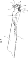
- reference numeral 1 denotes an apparatus for putting on flippers 2 (illustrated partially in Figures 1 and 7 ), such as, for example, flippers for underwater swimmers, defined in their entirety as users, to which explicit reference will be made without losing in terms of general applicability.
- flippers will be used to refer to all footwear which can be used for various sporting activities such as underwater immersion, swimming and so on.
- the flipper 2 to which reference is made herein comprises a part for inserting the underwater swimmer's foot which will be referred-to as a shoe 3, and a part that comprises a blade 4 which is constituted for generating a large portion of propulsion.
- the blade 4 has a flexible laminar shape, constituting the flipper proper, and is illustrated only partially in Figure 1 , the flipper 2 being interrupted by a saw-toothed line.
- the shoe 3 of the flipper 2 is without a rear containing part, that is to say, a rear part open at the position of the user's heel, so as to enable introduction of the foot in a housing 5, which constitutes the seating for the foot.
- the apparatus 1 comprises means 10 for retaining the foot of the underwater swimmer in the correct position inside the housing 5 of the flipper 2 and comprises means 9 for connecting to the flipper 2.
- the retaining means 10 and the connecting means 9 are mechanically connected to one another.
- the connecting means 9 allow the apparatus 1 to be connected to the shoe 3 of the flipper 2 in a removable fashion.
- Figure 7 illustrates a flipper 2 which comprises the apparatus 1 for putting it on, that is, the apparatus 1 constitutes a single piece with the flipper 2 since it is connected to it in an irremovable fashion.
- the connecting means 9 may be considered as means by which the apparatus is connected to the flipper 2 without the possibility of removal.
- the means 9 for connecting to the flipper 2 comprise a pair of jaws 6, which in a preferred embodiment are each made with a respective plate 7, defining a substantially "U" or ring shape.
- the two plates 7 are facing each other and spaced by an amount such as to enable insertion of a base or sole 8 of the shoe 3 of the flipper 2.
- the distance between the two plates 7 is therefore approximately the thickness of the material which forms the sole 8.
- the two plates 7 of the jaws 6 are pivoted to each other on an axis, parallel to the plane on which they lie, through a pair of pins 6a, which are coaxial with each other.
- the connecting means 9 are therefore associable in a removable fashion to a portion of the base 8 of the shoe 3, at least according to the embodiment illustrated in Figures 1 to 6 .
- the sole 8 of the shoe 3 is interposed between a lower plate 7a, positioned beneath the sole 8 of the flipper 2, and an upper plate 7b, positioned above the sole 8 and partly inside the housing 5 (see Figure 1 ).
- one of the jaws 6 of the connecting means 9 is connected to an element 11 for connecting between the jaw 6, consequently between the connecting means 9, and the retaining means 10.
- the spindle 14 in the hole 13 constitutes a hinge 15 in which the retaining means 10 are pivoted.
- the retaining means 10 and the connecting means 9 are mechanically pivoted to each other by means of the hinge 15.
- the retaining means 10 are partly located in the seat of a recess 16 made in the end 12 of the element 11 and have a passage which is able to partly house the spindle 14, which passes through a suitable through hole.
- the spindle 14 can be rigidly connected to the element 11 and the retaining means 10 remain free to rotate about it.
- the spindle 14 can be rigidly connected to the retaining means 10 and free to rotate inside the holes 13 of the element 11.
- the retaining means 10 of the heel of the foot comprise a structure which has various characteristics.
- the retaining means 10 comprise a first end 17 that engages in the recess 16.
- a zone 18 for opposing the heel which in turn comprises a guide 19 joined on the opposite side relative to a die 29 having an anatomical shape, in use facing towards and in contact with the heel of the wearer.
- This die 29 constitutes a supporting seat of the heel when the apparatus is in use.
- the strap 26, housed in the seat 25, can slide the slider 20, when the action of its elastic force is overcome by the wearer's foot.
- the retaining means 10 comprise a second upper end 27, opposite the first end 17, which extends in an inclined and/or curved fashion so as to facilitate rotation about the hinge 15.
- the apparatus 1 also comprises means 30 (illustrated in Figures 2 to 6 ) for adjusting the reciprocal position between the retaining means 10 and the connecting means 9.
- the adjusting means 30 are adjustable between two limit positions mutually towards and away between the retaining means 10 and the connecting means 9.
- the adjustment means 30 comprise an upper plate 21 and a lower plate 22, which are able to couple together and be mutually positioned.
- the upper plate 21 is rigidly connected to the connecting element 11.
- the connecting element 11 makes the upper plate 21 of the adjusting means 30 integral with the retaining means 10.
- the upper plate 21 is rigidly connected to one of the jaws 6.
- the lower plate 22 is connected to a jaw 6, in particular to the relative plate 7b.
- the mutual positioning between the plates 21 and 22 is made possible by the sliding of the locking means 23, that is to say, of the screws 23, in mutual slots 24.
- the stability of the positioning between the plates 21 and 22 is advantageously achieved by the presence, on their sides facing each other, of grooves 21a and 22a which can be coupled to each other and which are able to reach stable positions following the blocking of the locking means 23, that is to say, of the screws 23, but even if the screws 23 are not completely tightened.
- Figures 3 and 5 illustrate the apparatus 1 with the adjusting means 30 in the mutually towards end position in which the plates 21 and 22 are positioned in such a way that the retaining means 10 are as close as possible to the shoe 3 of the flipper 2.
- Figures 2 , 4 and 6 illustrate, on the other hand, the apparatus 1 with the adjusting means 30 in the mutually away end position, in which the plates 21 and 22 are each other positioned in such a way that the retaining means 10 are as far away as possible from the shoe 3 of the flipper 2.
- the most advanced end position will be ideal for the user who has shorter feet, whilst the most retracted end position will be ideal for the user who has longer feet.
- All the intermediate positions are adjustable and adaptable to all the intermediate lengths of the feet of the various users.
- the two plates 21 and 22 After positioning the foot and allowing the retaining means 10 to reach their operating position, the two plates 21 and 22 must be mutually positioned in such a way as to reach the position of greatest comfort.
- the user After withdrawing the foot from the shoe, the user must act on the locking means 23, tightening the screws 23, and from that moment the apparatus 1 will be perfectly adapted to the length of the user's foot without having to further make other adjustments.
- the flipper is thus ready for each future use by the same user.
- the apparatus 1 is, therefore, now be able to operate in exactly the same way as that described in patent number 1.423.616 of the same Applicant as this invention.
- connecting means 9 might also be integrated in the shoe 3 of the flipper 2, but that does not alter the fact that there are adjusting means 30 for adjusting the distance of the retaining means 10 from the connecting means 9, and, therefore, from the shoe 3.
- this solution does not comprise the use of the jaws 6, since they are not necessary, and, consequently, the lower plate 22 of the adjusting means 30 is connected to the shoe 3 of the flipper.
Landscapes
- Health & Medical Sciences (AREA)
- General Health & Medical Sciences (AREA)
- Physical Education & Sports Medicine (AREA)
- Footwear And Its Accessory, Manufacturing Method And Apparatuses (AREA)
- Thermotherapy And Cooling Therapy Devices (AREA)
- Finger-Pressure Massage (AREA)
- Adornments (AREA)
Claims (9)
- Appareil pour mettre des palmes (2) comprenant des moyens de retenue (10) servant à retenir le pied d'un utilisateur à l'intérieur d'un élément chaussant (3) de la palme (2), les moyens de retenue (10) étant reliés mécaniquement à des moyens de raccordement (9) pour le raccordement à l'élément chaussant (3) de la palme (2), les moyens de retenue (10) étant également montés pivotants sur les moyens de raccordement (9) par une charnière (15), l'appareil comprenant des moyens de réglage (30) servant à régler la position mutuelle entre les moyens de retenue (10) et les moyens de raccordement (9) ;
caractérisé en ce que les moyens de réglage (30) comprennent une plaque supérieure (21) et une plaque inférieure (22), pouvant s'accoupler et être mutuellement positionnées ;
l'appareil (1) comprend un élément (11) destiné au raccordement entre la plaque supérieure (21) et les moyens de retenue (10) ;
l'élément (11) est monté pivotant par la charnière (15) sur les moyens de retenue (10). - Appareil selon la revendication 1, caractérisé en ce que les moyens de réglage (30) sont réglables au moins entre des positions finales mutuellement rapprochées et mutuellement éloignées entre les moyens de retenue (10) et les moyens de raccordement (9).
- Appareil selon la revendication 1, caractérisé en ce que les moyens de réglage (30) comprennent des moyens de verrouillage (23), de préférence une paire de vis (23), servant à verrouiller mutuellement la plaque supérieure (21) et la plaque inférieure (22).
- Appareil selon la revendication 1, caractérisé en ce que la plaque supérieure (21) comporte des premières rainures (21a) et la plaque inférieure (22) comporte des secondes rainures (22a) ; les premières rainures (21a) et les secondes rainures (22a) étant couplées les unes aux autres et pouvant atteindre des positions stables.
- Appareil selon l'une quelconque des revendications précédentes, caractérisé en ce que les moyens de retenue comprennent un guide (19) sur lequel coulisse un curseur (20) glissant entre une position supérieure et une position inférieure.
- Appareil selon l'une quelconque des revendications précédentes, caractérisé en ce que les moyens de raccordement (9) sont amovibles et comprennent une paire de mâchoires (6).
- Appareil selon la revendication 6, caractérisé en ce que la plaque inférieure (22) des moyens de réglage (30) est reliée de manière rigide à une mâchoire (6) définissant les moyens de raccordement (9).
- Palme comprenant l'appareil selon l'une quelconque des revendications 1 à 5.
- Palme selon la revendication 8, caractérisée en ce que la plaque inférieure (22) des moyens de réglage (30) est reliée à l'élément chaussant (3) de la palme (2).
Applications Claiming Priority (2)
| Application Number | Priority Date | Filing Date | Title |
|---|---|---|---|
| IT102016000121316A IT201600121316A1 (it) | 2016-11-30 | 2016-11-30 | Apparecchiatura per indossare pinne. |
| PCT/IB2017/057435 WO2018100482A1 (fr) | 2016-11-30 | 2017-11-28 | Appareil de port de palmes |
Publications (2)
| Publication Number | Publication Date |
|---|---|
| EP3548151A1 EP3548151A1 (fr) | 2019-10-09 |
| EP3548151B1 true EP3548151B1 (fr) | 2020-08-19 |
Family
ID=58401991
Family Applications (1)
| Application Number | Title | Priority Date | Filing Date |
|---|---|---|---|
| EP17817149.2A Active EP3548151B1 (fr) | 2016-11-30 | 2017-11-28 | Appareil de port de palmes |
Country Status (4)
| Country | Link |
|---|---|
| US (1) | US11141627B2 (fr) |
| EP (1) | EP3548151B1 (fr) |
| IT (1) | IT201600121316A1 (fr) |
| WO (1) | WO2018100482A1 (fr) |
Family Cites Families (11)
| Publication number | Priority date | Publication date | Assignee | Title |
|---|---|---|---|---|
| US4017925A (en) * | 1975-01-14 | 1977-04-19 | Farallon Industries, Inc. | Swim fin including means for restricting ankle movement |
| JPH0530448Y2 (fr) | 1986-11-12 | 1993-08-04 | ||
| US5083954A (en) * | 1990-01-19 | 1992-01-28 | Jacobs Edward R | Swim fin retainer |
| IT1256836B (it) * | 1992-06-03 | 1995-12-21 | Technisub Spa | Pinna per il nuoto. |
| ITGE940079A1 (it) | 1994-06-16 | 1995-12-16 | Htm Sport Spa | Pinna da nuoto munita di fibbia per l'agganciamento del cinghiolo a |
| US5683279A (en) * | 1995-11-16 | 1997-11-04 | Dacor Corporation | Multi-part diving fin |
| FR2744639B1 (fr) | 1996-02-12 | 2000-09-15 | Dessault Danielle | Palme de natation a pointure variable |
| GB9719089D0 (en) | 1997-09-10 | 1997-11-12 | Scott Edward | Apparatus for fastening open heel footwear,including swimming fins |
| IT1311647B1 (it) * | 1999-04-28 | 2002-03-14 | Benetton Spa | Struttura di telaio, particolarmente per pattini con ruote in linea oda ghiaccio. |
| US10058737B2 (en) * | 2014-05-19 | 2018-08-28 | Paolo PIUMATTI | Apparatus for wearing fins |
| DE102014015712A1 (de) * | 2014-10-23 | 2016-04-28 | Karl Wilhelm Frasch | Tauchflosse oder Tauchschuh |
-
2016
- 2016-11-30 IT IT102016000121316A patent/IT201600121316A1/it unknown
-
2017
- 2017-11-28 US US16/464,984 patent/US11141627B2/en active Active
- 2017-11-28 EP EP17817149.2A patent/EP3548151B1/fr active Active
- 2017-11-28 WO PCT/IB2017/057435 patent/WO2018100482A1/fr not_active Ceased
Also Published As
| Publication number | Publication date |
|---|---|
| EP3548151A1 (fr) | 2019-10-09 |
| US20190321685A1 (en) | 2019-10-24 |
| IT201600121316A1 (it) | 2018-05-30 |
| US11141627B2 (en) | 2021-10-12 |
| WO2018100482A1 (fr) | 2018-06-07 |
Similar Documents
| Publication | Publication Date | Title |
|---|---|---|
| JP6554469B2 (ja) | ワイヤの締付装置及びその装着方法 | |
| EP3145601B1 (fr) | Appareil permettant d'enfiler des palmes | |
| US7003811B2 (en) | Detachable and rotatable clip | |
| US7654012B2 (en) | Closure device for shoe | |
| JP6042105B2 (ja) | ストラップ | |
| US8381415B1 (en) | Flip-flop back strap device | |
| EP3171949B1 (fr) | Appareil de transport pour équipement de ski | |
| WO2016023093A1 (fr) | Chaussure modulable | |
| US20140096313A1 (en) | Strap | |
| US20180084858A1 (en) | Universal chin guard assembly | |
| EP3548151B1 (fr) | Appareil de port de palmes | |
| CN204393548U (zh) | 方便调节表带长度的表扣 | |
| US3936064A (en) | Safety ski binding | |
| US10772439B2 (en) | Safety harness with adjustable separation mechanism | |
| KR102298250B1 (ko) | 와이어 조임장치 | |
| CN209967617U (zh) | 一种可调式滑雪板固定器 | |
| CN101559277B (zh) | 脚蹼 | |
| CN210992919U (zh) | 一种便于穿戴固定的滑雪固定器 | |
| US3765694A (en) | Safety harness or strap for ski boots | |
| KR20080092203A (ko) | 혁대의 자동신축장치 | |
| US11330924B2 (en) | Device and method for aiding putting on a ski boot | |
| US4036510A (en) | Safety ski binding | |
| US20120102692A1 (en) | Tightening strap of a diving flipper | |
| CN205374897U (zh) | 可收纳于眼镜镜脚的束带结构 | |
| KR200482896Y1 (ko) | 시계줄 분리도구가 결합된 손목시계 |
Legal Events
| Date | Code | Title | Description |
|---|---|---|---|
| STAA | Information on the status of an ep patent application or granted ep patent |
Free format text: STATUS: UNKNOWN |
|
| STAA | Information on the status of an ep patent application or granted ep patent |
Free format text: STATUS: THE INTERNATIONAL PUBLICATION HAS BEEN MADE |
|
| PUAI | Public reference made under article 153(3) epc to a published international application that has entered the european phase |
Free format text: ORIGINAL CODE: 0009012 |
|
| STAA | Information on the status of an ep patent application or granted ep patent |
Free format text: STATUS: REQUEST FOR EXAMINATION WAS MADE |
|
| 17P | Request for examination filed |
Effective date: 20190618 |
|
| AK | Designated contracting states |
Kind code of ref document: A1 Designated state(s): AL AT BE BG CH CY CZ DE DK EE ES FI FR GB GR HR HU IE IS IT LI LT LU LV MC MK MT NL NO PL PT RO RS SE SI SK SM TR |
|
| AX | Request for extension of the european patent |
Extension state: BA ME |
|
| DAV | Request for validation of the european patent (deleted) | ||
| DAX | Request for extension of the european patent (deleted) | ||
| GRAP | Despatch of communication of intention to grant a patent |
Free format text: ORIGINAL CODE: EPIDOSNIGR1 |
|
| STAA | Information on the status of an ep patent application or granted ep patent |
Free format text: STATUS: GRANT OF PATENT IS INTENDED |
|
| INTG | Intention to grant announced |
Effective date: 20200407 |
|
| GRAS | Grant fee paid |
Free format text: ORIGINAL CODE: EPIDOSNIGR3 |
|
| GRAA | (expected) grant |
Free format text: ORIGINAL CODE: 0009210 |
|
| STAA | Information on the status of an ep patent application or granted ep patent |
Free format text: STATUS: THE PATENT HAS BEEN GRANTED |
|
| AK | Designated contracting states |
Kind code of ref document: B1 Designated state(s): AL AT BE BG CH CY CZ DE DK EE ES FI FR GB GR HR HU IE IS IT LI LT LU LV MC MK MT NL NO PL PT RO RS SE SI SK SM TR |
|
| REG | Reference to a national code |
Ref country code: CH Ref legal event code: EP |
|
| REG | Reference to a national code |
Ref country code: DE Ref legal event code: R096 Ref document number: 602017022143 Country of ref document: DE |
|
| REG | Reference to a national code |
Ref country code: AT Ref legal event code: REF Ref document number: 1303285 Country of ref document: AT Kind code of ref document: T Effective date: 20200915 |
|
| REG | Reference to a national code |
Ref country code: IE Ref legal event code: FG4D |
|
| REG | Reference to a national code |
Ref country code: LT Ref legal event code: MG4D |
|
| REG | Reference to a national code |
Ref country code: NL Ref legal event code: MP Effective date: 20200819 |
|
| PG25 | Lapsed in a contracting state [announced via postgrant information from national office to epo] |
Ref country code: NO Free format text: LAPSE BECAUSE OF FAILURE TO SUBMIT A TRANSLATION OF THE DESCRIPTION OR TO PAY THE FEE WITHIN THE PRESCRIBED TIME-LIMIT Effective date: 20201119 Ref country code: BG Free format text: LAPSE BECAUSE OF FAILURE TO SUBMIT A TRANSLATION OF THE DESCRIPTION OR TO PAY THE FEE WITHIN THE PRESCRIBED TIME-LIMIT Effective date: 20201119 Ref country code: SE Free format text: LAPSE BECAUSE OF FAILURE TO SUBMIT A TRANSLATION OF THE DESCRIPTION OR TO PAY THE FEE WITHIN THE PRESCRIBED TIME-LIMIT Effective date: 20200819 Ref country code: HR Free format text: LAPSE BECAUSE OF FAILURE TO SUBMIT A TRANSLATION OF THE DESCRIPTION OR TO PAY THE FEE WITHIN THE PRESCRIBED TIME-LIMIT Effective date: 20200819 Ref country code: PT Free format text: LAPSE BECAUSE OF FAILURE TO SUBMIT A TRANSLATION OF THE DESCRIPTION OR TO PAY THE FEE WITHIN THE PRESCRIBED TIME-LIMIT Effective date: 20201221 Ref country code: FI Free format text: LAPSE BECAUSE OF FAILURE TO SUBMIT A TRANSLATION OF THE DESCRIPTION OR TO PAY THE FEE WITHIN THE PRESCRIBED TIME-LIMIT Effective date: 20200819 Ref country code: LT Free format text: LAPSE BECAUSE OF FAILURE TO SUBMIT A TRANSLATION OF THE DESCRIPTION OR TO PAY THE FEE WITHIN THE PRESCRIBED TIME-LIMIT Effective date: 20200819 Ref country code: GR Free format text: LAPSE BECAUSE OF FAILURE TO SUBMIT A TRANSLATION OF THE DESCRIPTION OR TO PAY THE FEE WITHIN THE PRESCRIBED TIME-LIMIT Effective date: 20201120 |
|
| REG | Reference to a national code |
Ref country code: AT Ref legal event code: MK05 Ref document number: 1303285 Country of ref document: AT Kind code of ref document: T Effective date: 20200819 |
|
| PG25 | Lapsed in a contracting state [announced via postgrant information from national office to epo] |
Ref country code: LV Free format text: LAPSE BECAUSE OF FAILURE TO SUBMIT A TRANSLATION OF THE DESCRIPTION OR TO PAY THE FEE WITHIN THE PRESCRIBED TIME-LIMIT Effective date: 20200819 Ref country code: NL Free format text: LAPSE BECAUSE OF FAILURE TO SUBMIT A TRANSLATION OF THE DESCRIPTION OR TO PAY THE FEE WITHIN THE PRESCRIBED TIME-LIMIT Effective date: 20200819 Ref country code: PL Free format text: LAPSE BECAUSE OF FAILURE TO SUBMIT A TRANSLATION OF THE DESCRIPTION OR TO PAY THE FEE WITHIN THE PRESCRIBED TIME-LIMIT Effective date: 20200819 Ref country code: RS Free format text: LAPSE BECAUSE OF FAILURE TO SUBMIT A TRANSLATION OF THE DESCRIPTION OR TO PAY THE FEE WITHIN THE PRESCRIBED TIME-LIMIT Effective date: 20200819 Ref country code: IS Free format text: LAPSE BECAUSE OF FAILURE TO SUBMIT A TRANSLATION OF THE DESCRIPTION OR TO PAY THE FEE WITHIN THE PRESCRIBED TIME-LIMIT Effective date: 20201219 |
|
| PG25 | Lapsed in a contracting state [announced via postgrant information from national office to epo] |
Ref country code: EE Free format text: LAPSE BECAUSE OF FAILURE TO SUBMIT A TRANSLATION OF THE DESCRIPTION OR TO PAY THE FEE WITHIN THE PRESCRIBED TIME-LIMIT Effective date: 20200819 Ref country code: RO Free format text: LAPSE BECAUSE OF FAILURE TO SUBMIT A TRANSLATION OF THE DESCRIPTION OR TO PAY THE FEE WITHIN THE PRESCRIBED TIME-LIMIT Effective date: 20200819 Ref country code: CZ Free format text: LAPSE BECAUSE OF FAILURE TO SUBMIT A TRANSLATION OF THE DESCRIPTION OR TO PAY THE FEE WITHIN THE PRESCRIBED TIME-LIMIT Effective date: 20200819 Ref country code: DK Free format text: LAPSE BECAUSE OF FAILURE TO SUBMIT A TRANSLATION OF THE DESCRIPTION OR TO PAY THE FEE WITHIN THE PRESCRIBED TIME-LIMIT Effective date: 20200819 Ref country code: SM Free format text: LAPSE BECAUSE OF FAILURE TO SUBMIT A TRANSLATION OF THE DESCRIPTION OR TO PAY THE FEE WITHIN THE PRESCRIBED TIME-LIMIT Effective date: 20200819 |
|
| REG | Reference to a national code |
Ref country code: DE Ref legal event code: R097 Ref document number: 602017022143 Country of ref document: DE |
|
| PG25 | Lapsed in a contracting state [announced via postgrant information from national office to epo] |
Ref country code: AT Free format text: LAPSE BECAUSE OF FAILURE TO SUBMIT A TRANSLATION OF THE DESCRIPTION OR TO PAY THE FEE WITHIN THE PRESCRIBED TIME-LIMIT Effective date: 20200819 Ref country code: AL Free format text: LAPSE BECAUSE OF FAILURE TO SUBMIT A TRANSLATION OF THE DESCRIPTION OR TO PAY THE FEE WITHIN THE PRESCRIBED TIME-LIMIT Effective date: 20200819 Ref country code: ES Free format text: LAPSE BECAUSE OF FAILURE TO SUBMIT A TRANSLATION OF THE DESCRIPTION OR TO PAY THE FEE WITHIN THE PRESCRIBED TIME-LIMIT Effective date: 20200819 |
|
| PLBE | No opposition filed within time limit |
Free format text: ORIGINAL CODE: 0009261 |
|
| STAA | Information on the status of an ep patent application or granted ep patent |
Free format text: STATUS: NO OPPOSITION FILED WITHIN TIME LIMIT |
|
| PG25 | Lapsed in a contracting state [announced via postgrant information from national office to epo] |
Ref country code: MC Free format text: LAPSE BECAUSE OF FAILURE TO SUBMIT A TRANSLATION OF THE DESCRIPTION OR TO PAY THE FEE WITHIN THE PRESCRIBED TIME-LIMIT Effective date: 20200819 Ref country code: SK Free format text: LAPSE BECAUSE OF FAILURE TO SUBMIT A TRANSLATION OF THE DESCRIPTION OR TO PAY THE FEE WITHIN THE PRESCRIBED TIME-LIMIT Effective date: 20200819 |
|
| REG | Reference to a national code |
Ref country code: CH Ref legal event code: PL |
|
| 26N | No opposition filed |
Effective date: 20210520 |
|
| PG25 | Lapsed in a contracting state [announced via postgrant information from national office to epo] |
Ref country code: LU Free format text: LAPSE BECAUSE OF NON-PAYMENT OF DUE FEES Effective date: 20201128 |
|
| REG | Reference to a national code |
Ref country code: BE Ref legal event code: MM Effective date: 20201130 |
|
| PG25 | Lapsed in a contracting state [announced via postgrant information from national office to epo] |
Ref country code: SI Free format text: LAPSE BECAUSE OF FAILURE TO SUBMIT A TRANSLATION OF THE DESCRIPTION OR TO PAY THE FEE WITHIN THE PRESCRIBED TIME-LIMIT Effective date: 20200819 Ref country code: LI Free format text: LAPSE BECAUSE OF NON-PAYMENT OF DUE FEES Effective date: 20201130 Ref country code: CH Free format text: LAPSE BECAUSE OF NON-PAYMENT OF DUE FEES Effective date: 20201130 |
|
| PG25 | Lapsed in a contracting state [announced via postgrant information from national office to epo] |
Ref country code: IE Free format text: LAPSE BECAUSE OF NON-PAYMENT OF DUE FEES Effective date: 20201128 |
|
| PG25 | Lapsed in a contracting state [announced via postgrant information from national office to epo] |
Ref country code: TR Free format text: LAPSE BECAUSE OF FAILURE TO SUBMIT A TRANSLATION OF THE DESCRIPTION OR TO PAY THE FEE WITHIN THE PRESCRIBED TIME-LIMIT Effective date: 20200819 Ref country code: MT Free format text: LAPSE BECAUSE OF FAILURE TO SUBMIT A TRANSLATION OF THE DESCRIPTION OR TO PAY THE FEE WITHIN THE PRESCRIBED TIME-LIMIT Effective date: 20200819 Ref country code: CY Free format text: LAPSE BECAUSE OF FAILURE TO SUBMIT A TRANSLATION OF THE DESCRIPTION OR TO PAY THE FEE WITHIN THE PRESCRIBED TIME-LIMIT Effective date: 20200819 |
|
| PG25 | Lapsed in a contracting state [announced via postgrant information from national office to epo] |
Ref country code: MK Free format text: LAPSE BECAUSE OF FAILURE TO SUBMIT A TRANSLATION OF THE DESCRIPTION OR TO PAY THE FEE WITHIN THE PRESCRIBED TIME-LIMIT Effective date: 20200819 |
|
| PG25 | Lapsed in a contracting state [announced via postgrant information from national office to epo] |
Ref country code: BE Free format text: LAPSE BECAUSE OF NON-PAYMENT OF DUE FEES Effective date: 20201130 |
|
| P01 | Opt-out of the competence of the unified patent court (upc) registered |
Effective date: 20230414 |
|
| PGFP | Annual fee paid to national office [announced via postgrant information from national office to epo] |
Ref country code: GB Payment date: 20251125 Year of fee payment: 9 |
|
| PGFP | Annual fee paid to national office [announced via postgrant information from national office to epo] |
Ref country code: IT Payment date: 20251117 Year of fee payment: 9 |
|
| PGFP | Annual fee paid to national office [announced via postgrant information from national office to epo] |
Ref country code: FR Payment date: 20251124 Year of fee payment: 9 |
|
| PGFP | Annual fee paid to national office [announced via postgrant information from national office to epo] |
Ref country code: DE Payment date: 20260127 Year of fee payment: 9 |