EP3146134B1 - Einstellbare vertikalaussteifung mit kulisse für einen abstellbaren flügel eines fensters oder einer tür - Google Patents
Einstellbare vertikalaussteifung mit kulisse für einen abstellbaren flügel eines fensters oder einer tür Download PDFInfo
- Publication number
- EP3146134B1 EP3146134B1 EP15719215.4A EP15719215A EP3146134B1 EP 3146134 B1 EP3146134 B1 EP 3146134B1 EP 15719215 A EP15719215 A EP 15719215A EP 3146134 B1 EP3146134 B1 EP 3146134B1
- Authority
- EP
- European Patent Office
- Prior art keywords
- vertical reinforcement
- longitudinal axis
- displacement means
- vertical
- reinforcement according
- Prior art date
- Legal status (The legal status is an assumption and is not a legal conclusion. Google has not performed a legal analysis and makes no representation as to the accuracy of the status listed.)
- Active
Links
Images
Classifications
-
- E—FIXED CONSTRUCTIONS
- E05—LOCKS; KEYS; WINDOW OR DOOR FITTINGS; SAFES
- E05D—HINGES OR SUSPENSION DEVICES FOR DOORS, WINDOWS OR WINGS
- E05D15/00—Suspension arrangements for wings
- E05D15/06—Suspension arrangements for wings for wings sliding horizontally more or less in their own plane
- E05D15/10—Suspension arrangements for wings for wings sliding horizontally more or less in their own plane movable out of one plane into a second parallel plane
- E05D15/1005—Suspension arrangements for wings for wings sliding horizontally more or less in their own plane movable out of one plane into a second parallel plane the wing being supported on arms movable in horizontal planes
- E05D15/1013—Suspension arrangements for wings for wings sliding horizontally more or less in their own plane movable out of one plane into a second parallel plane the wing being supported on arms movable in horizontal planes specially adapted for windows
-
- E—FIXED CONSTRUCTIONS
- E05—LOCKS; KEYS; WINDOW OR DOOR FITTINGS; SAFES
- E05Y—INDEXING SCHEME ASSOCIATED WITH SUBCLASSES E05D AND E05F, RELATING TO CONSTRUCTION ELEMENTS, ELECTRIC CONTROL, POWER SUPPLY, POWER SIGNAL OR TRANSMISSION, USER INTERFACES, MOUNTING OR COUPLING, DETAILS, ACCESSORIES, AUXILIARY OPERATIONS NOT OTHERWISE PROVIDED FOR, APPLICATION THEREOF
- E05Y2201/00—Constructional elements; Accessories therefor
- E05Y2201/60—Suspension or transmission members; Accessories therefor
- E05Y2201/622—Suspension or transmission members elements
- E05Y2201/638—Cams; Ramps
-
- E—FIXED CONSTRUCTIONS
- E05—LOCKS; KEYS; WINDOW OR DOOR FITTINGS; SAFES
- E05Y—INDEXING SCHEME ASSOCIATED WITH SUBCLASSES E05D AND E05F, RELATING TO CONSTRUCTION ELEMENTS, ELECTRIC CONTROL, POWER SUPPLY, POWER SIGNAL OR TRANSMISSION, USER INTERFACES, MOUNTING OR COUPLING, DETAILS, ACCESSORIES, AUXILIARY OPERATIONS NOT OTHERWISE PROVIDED FOR, APPLICATION THEREOF
- E05Y2600/00—Mounting or coupling arrangements for elements provided for in this subclass
- E05Y2600/10—Adjustable
- E05Y2600/20—Adjustable with specific transmission movement
-
- E—FIXED CONSTRUCTIONS
- E05—LOCKS; KEYS; WINDOW OR DOOR FITTINGS; SAFES
- E05Y—INDEXING SCHEME ASSOCIATED WITH SUBCLASSES E05D AND E05F, RELATING TO CONSTRUCTION ELEMENTS, ELECTRIC CONTROL, POWER SUPPLY, POWER SIGNAL OR TRANSMISSION, USER INTERFACES, MOUNTING OR COUPLING, DETAILS, ACCESSORIES, AUXILIARY OPERATIONS NOT OTHERWISE PROVIDED FOR, APPLICATION THEREOF
- E05Y2600/00—Mounting or coupling arrangements for elements provided for in this subclass
- E05Y2600/10—Adjustable
- E05Y2600/30—Adjustment motion
- E05Y2600/31—Linear motion
- E05Y2600/312—Horizontal motion
-
- E—FIXED CONSTRUCTIONS
- E05—LOCKS; KEYS; WINDOW OR DOOR FITTINGS; SAFES
- E05Y—INDEXING SCHEME ASSOCIATED WITH SUBCLASSES E05D AND E05F, RELATING TO CONSTRUCTION ELEMENTS, ELECTRIC CONTROL, POWER SUPPLY, POWER SIGNAL OR TRANSMISSION, USER INTERFACES, MOUNTING OR COUPLING, DETAILS, ACCESSORIES, AUXILIARY OPERATIONS NOT OTHERWISE PROVIDED FOR, APPLICATION THEREOF
- E05Y2600/00—Mounting or coupling arrangements for elements provided for in this subclass
- E05Y2600/60—Mounting or coupling members; Accessories therefor
- E05Y2600/62—Bolts
-
- E—FIXED CONSTRUCTIONS
- E05—LOCKS; KEYS; WINDOW OR DOOR FITTINGS; SAFES
- E05Y—INDEXING SCHEME ASSOCIATED WITH SUBCLASSES E05D AND E05F, RELATING TO CONSTRUCTION ELEMENTS, ELECTRIC CONTROL, POWER SUPPLY, POWER SIGNAL OR TRANSMISSION, USER INTERFACES, MOUNTING OR COUPLING, DETAILS, ACCESSORIES, AUXILIARY OPERATIONS NOT OTHERWISE PROVIDED FOR, APPLICATION THEREOF
- E05Y2800/00—Details, accessories and auxiliary operations not otherwise provided for
- E05Y2800/15—Applicability
- E05Y2800/17—Universally applicable
- E05Y2800/176—Universally applicable on different wing types, weights or sizes
-
- E—FIXED CONSTRUCTIONS
- E05—LOCKS; KEYS; WINDOW OR DOOR FITTINGS; SAFES
- E05Y—INDEXING SCHEME ASSOCIATED WITH SUBCLASSES E05D AND E05F, RELATING TO CONSTRUCTION ELEMENTS, ELECTRIC CONTROL, POWER SUPPLY, POWER SIGNAL OR TRANSMISSION, USER INTERFACES, MOUNTING OR COUPLING, DETAILS, ACCESSORIES, AUXILIARY OPERATIONS NOT OTHERWISE PROVIDED FOR, APPLICATION THEREOF
- E05Y2800/00—Details, accessories and auxiliary operations not otherwise provided for
- E05Y2800/67—Materials; Strength alteration thereof
- E05Y2800/682—Strength alteration by reinforcing, e.g. by applying ribs
-
- E—FIXED CONSTRUCTIONS
- E05—LOCKS; KEYS; WINDOW OR DOOR FITTINGS; SAFES
- E05Y—INDEXING SCHEME ASSOCIATED WITH SUBCLASSES E05D AND E05F, RELATING TO CONSTRUCTION ELEMENTS, ELECTRIC CONTROL, POWER SUPPLY, POWER SIGNAL OR TRANSMISSION, USER INTERFACES, MOUNTING OR COUPLING, DETAILS, ACCESSORIES, AUXILIARY OPERATIONS NOT OTHERWISE PROVIDED FOR, APPLICATION THEREOF
- E05Y2900/00—Application of doors, windows, wings or fittings thereof
- E05Y2900/10—Application of doors, windows, wings or fittings thereof for buildings or parts thereof
- E05Y2900/13—Type of wing
- E05Y2900/148—Windows
Definitions
- the invention relates to an adjustable vertical stiffening for a movable wing of a window, a door or the like, wherein the vertical stiffening has a trained in the form of a bolt Abstellstoff whose first end is directly or indirectly mounted on a horizontal spar of the wing and the second end, the is opposite to the first end in the direction of the longitudinal axis of the Abstellstoffs, is coupled to a mounting member of the vertical stiffener, wherein the mounting member is mounted on a vertical spar of the wing.
- the fitting part has a projection.
- the projection acts in the form of a "deformation die", which generates a bias in the assembly of the fitting part to the wing, which compensates for a distortion of the wing due to the wing weight.
- the DE 87 09 299 U1 discloses a vertical stiffener for a support member of a deployable wing, wherein the vertical stiffener has a plate which can be screwed onto the wing.
- the DE 88 04 738 U1 discloses a fitting for a parkable via Ausstellarme door leaf.
- the door has a support member which is attached to a lower wing spar.
- the support member is stiffened by an elongated reinforcing member which is loosely arranged in the sash.
- the reinforcing member can be rigidly bolted to the support member.
- a bolted to a sliding wing vertical stiffening is further from the EP 0 443 176 A1 known.
- WO 2012/095806 A1 which describes the features of the preamble of claim 1, discloses a further development of DE 101 10 722 A1 ,
- a vertical stiffening for sliding sash which has a mounting element and a parking means.
- the mounting element is mounted on a vertical wing spar and the parking means is indirectly connected to a horizontal wing spar.
- Abstellstoff and mounting element are connected to each other via a screw whose longitudinal direction is aligned perpendicular to the wing main plane. By means of an actuation of the screw, the distance between the parking means and the mounting element can be adjusted. By changing this distance, the angle between the vertical wing spar and the horizontal wing spar changed.
- Warp compensation can be adjusted by the screw, depending on the amount of twist between the horizontal wing spar and the vertical wing spar. In other words, can be adjusted by the screw, how much of the bending away under the load of the wing horizontal wing spar again "pulled” on the vertical wing spar “pulled” or “pushed away” this.
- the known vertical stiffening is adjustable by a "screwing” or “unscrewing” the screw in the Abstellstoff or the vertical wing spar.
- the strength of the connection between Abstellstoff and mounting element or vertical wing spar varies due to the differently far screwed screw.
- the strength of the connection between Abstellstoff and mounting member or vertical wing spar depends on how far a user has screwed the screw to compensate for the distortion of the wing spars. This is from a comparison of FIGS. 2 to 4 as well as from a comparison of FIGS. 5a and 5b the WO 2012/095806 A1 seen.
- the invention is the object of the invention to provide an adjustable vertical stiffening for a shieldable wing of a window, a door or the like, in which the strength of the vertical stiffening is independent of the setting of the vertical stiffening.
- an adjustable vertical stiffening for a movable wing of a window, a door or the like, wherein the vertical stiffening has a trained in the form of a bolt Abstellstoff whose first end is directly or indirectly mounted on a horizontal spar of the wing and its second end, which is opposite to the first end in the direction of the longitudinal axis of the Abstellstoffs coupled to a mounting member of the vertical stiffener, wherein the mounting member is mounted on a vertical spar of the wing and wherein the vertical stiffening at least partially rotatably mounted on the mounting member arranged rotary member with a slotted guide has, which extends at least partially radially to the longitudinal axis of the rotary member and in the direction of the longitudinal axis of the rotary member rises, wherein the second end of the Abstellstoffs engages within the slotted guide in this.
- the at least partially radially extending to the longitudinal axis and increasing in the direction of the longitudinal axis slotted guide is in other words formed externally threaded portion.
- the slotted guide extends substantially between 160 ° and 200 ° radially to the longitudinal axis of the rotary member.
- the slotted guide is preferably formed only in sections on an outer side of the rotary member.
- the slotted guide extends substantially through 180 ° radially to the longitudinal axis of the rotary member. In this case, the user can turn the rotary element by ⁇ 90 ° for torsion compensation.
- the longitudinal axis of the Abstellstoffs extends parallel to the longitudinal axis of the mounting member, when the second end of the Abstellstoffs engages centrally in the longitudinal direction of the slotted guide in the slide guide.
- the vertical stiffening in this case is formed so that the longitudinal axes of the mounting member and the Abstellstoffs are parallel when the Abstellstoff centered in the slotted guide, wherein the center of the slotted guide "halfway" between the ends of the slotted guide is located.
- a user is thereby by means of rotation of the rotary element in a position to both "take” the Abstellstoff to the mounting element and the Abstellstoff "push away” of the mounting element.
- the slide guide is at least partially formed step-shaped.
- the set by a user position of the rotary member can be kept safe even under heavy load of the vertical stiffening.
- the step-shaped design of the slotted guide allows a discrete and thus better reproducible adjustment of the vertical stiffening.
- the vertical stiffening invention also allows the compensation of a strong twist when the slide guide has a stroke in the direction of the longitudinal axis of the rotary member of 4 mm to 6 mm, in particular of 5 mm.
- a stable, yet structurally simple and inexpensively manufacturable vertical stiffening can be achieved when the rotary member is rotatably riveted to the mounting element.
- a particularly convenient for the user setting the vertical stiffening is made possible when the rotary member has a mark for indicating the rotational position of the rotary member.
- the Marking can be arranged or formed on an end face of the rotary member.
- the marking is particularly preferably arranged or formed on the rotary element such that the marking in plan view of the rotary element is aligned with the parking means when the longitudinal axis of the parking means extends parallel to the longitudinal axis of the mounting element. The user can thus easily read at the mark that the vertical stiffening is in a "neutral position".
- the marking is in the form of a notch.
- the rotating element may have a tool engagement.
- the tool engagement is formed on an end face of the rotary member.
- the tool engagement is particularly preferably in the form of an inner polygon, for example, a hexagon socket (Allen) or a driving profile formed in multi-round shape (Torx).
- the costs for producing the vertical stiffening can be greatly reduced if the rotary element is designed as a cast part, in particular made of zinc.
- the production of the rotary element is further simplified if it is substantially cylindrical, wherein the slotted guide runs at least in sections on the lateral surface of the cylinder.
- the parking means is designed in the form of a steel bolt.
- the parking means preferably has in the region of its second end extending in the direction of the longitudinal axis of the parking means Longitudinal flattening in order to "draw” both the Abstellstoff close to the mounting element and to allow a compact formation of the vertical stiffening.
- the vertical stiffening is furthermore designed to be particularly compact if the mounting element is substantially plate-shaped, in particular in the form of a sheet, preferably in the form of a steel sheet.
- the vertical stiffening is structurally particularly simple in design, when the guide passage recess is formed in the form of a guide passage tab on the mounting member.
- the mounting element may have a first guide web which engages in a transverse to the direction of the longitudinal axis of the Abstellstoffs extending first transverse recess to hold the Abstellstoff rotationally fixed to the mounting member.
- the mounting element has a second guide web, which engages in a transverse to the direction of the longitudinal axis of the Abstellstoffs extending second transverse recess to hold the Abstellstoff rotationally fixed to the mounting member. A tilting of the Vertical stiffening upon actuation of the rotary member can be safely avoided.
- the vertical stiffening is structurally particularly simple and therefore inexpensive to manufacture, if the guide passage tab, the first guide bar and / or the second guide bar are integrally formed with the mounting member.
- the invention further relates to a window, a door or the like with a previously described vertical stiffening.
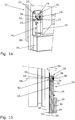
- FIG. 1a shows a first adjustable vertical stiffener 10 which is mounted on a removable wing 12 of a door.
- the first vertical reinforcement 10 has a parking means 14, a mounting element 16 and a rotary element 18.
- the mounting member 16 is by four screws mounted a vertical spar 20 of the wing 12. For reasons of clarity, the screws provided for this purpose, which are insertable into screw holes 22, 24, 26, 27 of the mounting element 16, are not shown.
- the parking means 14 is connected via a first end 28 with a horizontal rail 30 of the wing 12. Since the first end 28 in FIG. 1a is covered by the horizontal spar 30, the reference numeral 28 is shown in dashed lines.
- a second end 32 opposite the first end 28 engages a slotted guide 34 of the rotary member 18.
- FIG. 1b shows a sectional side view of the arrangement FIG. 1a with the first vertical stiffener 10.
- the parking means 14 is formed in the form of a bolt.
- the first end 28 of the parking means 14 is inserted into a recess 36, here in the form of a through-hole, of the horizontal spar 30.
- the second end 32 of the parking means 14 is arranged in the slotted guide 34.
- the rotary member 18 is formed substantially cylindrical. Its lateral surface has in sections the slotted guide 34.
- a first end face 38 of the rotary member 18 has a tool engagement 40 for insertion of a socket portion. At one of the first end face 38 opposite end face 42 of the rotary member 18, this has a substantially cylindrical projection 44.
- the projection 44 is rotatably disposed in a through-hole 46 of the mounting member 16.
- the projection 44 is riveted to the mounting member 16 in the region of the through-hole 46 in order to achieve a fixed connection of the rotary member 18 to the mounting member 16 in the direction of the longitudinal axis 48 of the rotary member 18.
- the first vertical stiffener 10 is in FIG. 1b shown in the neutral position.
- the parking means 14 can be pivoted in the direction of a double arrow 54 relative to the mounting member 16 to compensate for a distortion of the horizontal beam 30 relative to the vertical spar 20. This is especially true of the following FIGS. 2a to 4b clear.
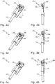
- FIG. 2a shows the first vertical stiffener 10 in a perspective view in the neutral position.
- the slide guide 34 extends substantially at 180 ° radially to the longitudinal axis 48 of the rotary member 18th
- FIG. 2b shows the first vertical stiffener 10 according to FIG. 2a in the side view, being off FIG. 2b it can be seen that the slide guide 34 is formed on a lateral surface 56 of the rotary member 18.
- FIG. 3a shows the first vertical stiffener 10 in a first end position. This can be seen for a user by a mark 58 on the first end face 38 of the rotary member 18. In the neutral position of the first vertical stiffener 10, the marking 58 is aligned with the Abstellstoff 14 (see FIG. 2a ).
- FIG. 3b shows a side view of the first vertical stiffening 10 according to FIG. 3a , Out FIG. 3b It can be seen that the parking means 14 has a longitudinal flat 59 in order to pivot the parking means 14 close to the mounting member 16 can. Out FIG. 3b Furthermore, it can be seen that the slotted guide 34 increases continuously and linearly in the direction of the longitudinal axis 48 of the rotary element 18. The Rotation of the rotary element 18 thus causes a linear pivoting of the parking means 14th
- FIG. 4a shows the first vertical stiffener 10 in a second end position. In this second end position, the parking means 14 is pivoted away from the mounting element 16 at a maximum.
- FIG. 4b shows the first vertical stiffener 10 in this second end position in a side view. From a comparison of FIGS. 3b and 4b It can be seen that the slotted guide 34 in the direction of the longitudinal axis 48 of the rotary member 18 has a stroke H.
- the stroke H in the present example, the first vertical stiffening 10 is about 5 mm.
- the second end 32 of the parking means 14 can be moved by rotation of the rotary member 18 by approximately ⁇ 2.5 mm relative to the mounting member 16.
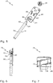
- FIG. 5 shows an itemized perspective view of the first vertical stiffening 10.
- the mounting member 16 is formed substantially plate-shaped.
- the mounting member 16 has a ceremoniess trimgangsausANSung 60, which represents a hinge point by which the Abstellstoff 14 is tilted by rotation of the rotary member 18.
- the ceremoniess trimgangsausANS 60 allows a particularly compact and solid design of the first vertical stiffening 10.
- the ceremoniess trimgangsausANSANS 60 is formed in a guide passage tab 61 on the mounting member 16.
- the mounting element 16 also has a first guide web 62, which engages in a transverse to the longitudinal axis 50 of the Abstellstoffs 14 extending first transverse recess 64.
- first guide web 62 engages in a transverse to the longitudinal axis 50 of the Abstellstoffs 14 extending first transverse recess 64.
- a second guide web 66 of the mounting element 16 engages in a second transverse recess 68, which extends transversely to the longitudinal axis 50 of the parking means 14.
- the guide passage tab 61 and the guide webs 62, 66 are formed integrally or integrally with the mounting member 16.
- FIG. 6 shows a second vertical stiffener 70, which is identical to the previously described first vertical stiffener 10. However, a slotted guide 72 of a rotary member 74 is step-shaped.
- FIG. 7 shows the rotary member 74 according to FIG. 6 in an enlarged view.
- the slide guide 72 has a plurality of steps 76, 78, 80, so that a second end 82 (see FIG. 6 ) of a parking means 84 is gradually pivoted by rotating the rotary member 74.
- a provision of the second vertical stiffening after adjustment by the user is reliably avoided.
- the invention relates to a vertical stiffening for a door or window sash.
- the vertical stiffener allows for twist compensation of a vertical stile relative to a horizontal spar of the door or window sash.
- the vertical stiffener has a bolt-shaped parking means, which is formed at one end for engagement in the horizontal rail and the other end engages in a rotary element of the vertical stiffening.
- the rotary member is rotatable about its longitudinal axis, but fixed in its direction of its longitudinal axis on a, in particular plate-shaped, mounting member arranged, which is attachable to the vertical spar.
- the rotary member has a slotted guide, in which engages one end of the Abstellstoffs.
- the slotted guide can be designed in steps.
- the rotary member preferably has a tool engagement on the front side for its actuation. A rotation of the rotary element causes a pivoting of the Abstellstoffs relative to the mounting element, whereby a twisting of the door or window sash is compensate
Landscapes
- Engineering & Computer Science (AREA)
- Mechanical Engineering (AREA)
- Body Structure For Vehicles (AREA)
- Hinges (AREA)
- Power-Operated Mechanisms For Wings (AREA)
- Pivots And Pivotal Connections (AREA)
- Door And Window Frames Mounted To Openings (AREA)
- Wing Frames And Configurations (AREA)
Description
- Die Erfindung betrifft eine einstellbare Vertikalaussteifung für einen abstellbaren Flügel eines Fensters, einer Tür oder dergleichen, wobei die Vertikalaussteifung ein in Form eines Bolzens ausgebildetes Abstellmittel aufweist, dessen erstes Ende mittelbar oder unmittelbar an einem horizontalen Holm des Flügels montierbar ist und dessen zweites Ende, das dem ersten Ende in Richtung der Längsachse des Abstellmittels entgegengesetzt ist, an ein Montageelement der Vertikalaussteifung gekoppelt ist, wobei das Montageelement an einen vertikalen Holm des Flügels montierbar ist.
- Bei abstellbaren Flügeln, insbesondere bei abstellbaren Schiebeflügeln, kann es bei besonders schweren Flügeln zu einem Absenken eines Ausstellarmes, an dem der Flügel abgestützt ist, kommen, wenn der Flügel abgestellt ist. Die Absenkung erschwert dann das Schließen des Flügels. Weiterhin kann es durch die Absenkung zu einem Bruch einer Schweißverbindung zwischen einem horizontalen Flügelholm und einem vertikalen Flügelholm des Flügels kommen. Ein Absenken des Ausstellarmes sowie ein Bruch der Verbindung zwischen horizontalem und vertikalem Flügelholm kann jedoch durch eine Vertikalaussteifung vermieden werden. Diese kann in einer Ecke des Flügels montiert werden, an der der horizontale Flügelholm und der vertikale Flügelholm verbunden sind. Die Vertikalaussteifung bewirkt eine Verwindungskompensation zwischen dem horizontalen Flügelholm und dem vertikalen Flügelholm.
- Aus der
EP 1 391 576 A1 ist es bekannt geworden, eine Verwindungskompensation abstellbarer Flügel durch eine Vertikalaussteifung in Form eines Beschlagteils vorzunehmen. Das Beschlagteil weist einen Vorsprung auf. Der Vorsprung wirkt in Form eines "Verformungsstempels", der bei der Montage des Beschlagteils an den Flügel eine Vorspannung erzeugt, die eine Verwindung des Flügels aufgrund des Flügelgewichts kompensiert. - Die
DE 87 09 299 U1 offenbart eine Vertikalaussteifung für ein Tragteil eines abstellbaren Flügels, wobei die Vertikalaussteifung eine auf den Flügel aufschraubbare Platte aufweist. - Aus der
DE 299 07 975 U1 ist weiterhin ein Abstützmittel für eine Schiebetür bekannt geworden, das als Winkelprofil ausgebildet ist. - Die
DE 88 04 738 U1 offenbart einen Beschlag für einen über Ausstellarme abstellbaren Türflügel. Der Türflügel weist einen Tragteil auf, der an einem unteren Flügelholm befestigt ist. Der Tragteil wird durch einen langgestreckten Verstärkungsteil versteift, der im Flügelfalz lose angeordnet ist. Der Verstärkungsteil kann starr mit dem Tragteil verschraubt werden. - Eine an einen Schiebeflügel anschraubbare Vertikalaussteifung ist weiterhin aus der
EP 0 443 176 A1 bekannt geworden. - Aus der
DE 101 10 722 A1 ist eine Vertikalaussteifung in Form einer Eckversteifung von Schiebeflügeln bekannt geworden, die ein vertikales Abstellmittel und ein fest mit dem Abstellmittel verbundenes Montagelement umfasst. - Die
WO 2012/095806 A1 , die die Merkmale des Oberbegriffs des Anspruchs 1 beschreibt, offenbart eine Weiterentwicklung derDE 101 10 722 A1 . Dabei wird eine Vertikalaussteifung für Schiebeflügel gezeigt, die ein Montageelement und ein Abstellmittel aufweist. Das Montageelement ist an einem vertikalen Flügelholm montiert und das Abstellmittel ist mittelbar mit einem horizontalen Flügelholm verbunden. Abstellmittel und Montageelement sind über eine Schraube miteinander verbunden, deren Längsrichtung senkrecht zur Flügelhauptebene ausgerichtet ist. Mittels einer Betätigung der Schraube kann der Abstand zwischen Abstellmittel und Montageelement eingestellt werden. Durch die Veränderung dieses Abstandes verändert sich auch der Winkel zwischen dem vertikalen Flügelholm und dem horizontalen Flügelholm. Die - Verwindungskompensation kann je nach Stärke der Verwindung zwischen horizontalem Flügelholm und vertikalem Flügelholm durch die Schraube eingestellt werden. Mit anderen Worten kann durch die Schraube eingestellt werden, wie stark der sich unter der Last des Flügel wegbiegende horizontale Flügelholm wieder an den vertikalen Flügelholm "herangezogen" bzw. von diesem "weggedrückt" wird.
- Die bekannte Vertikalaussteifung ist dabei durch ein "Einschrauben" bzw. "Ausschrauben" der Schraube in das Abstellmittel bzw. den vertikalen Flügelholm einstellbar. Allerdings variiert die Festigkeit der Verbindung zwischen Abstellmittel und Montageelement bzw. vertikalem Flügelholm aufgrund der unterschiedlich weit eingedrehten Schraube. Mit anderen Worten ist die Festigkeit der Verbindung zwischen Abstellmittel und Montageelement bzw. vertikalem Flügelholm abhängig davon, wie weit ein Benutzer die Schraube eingeschraubt hat, um die Verwindung der Flügelholme zu kompensieren. Dies ist aus einem Vergleich der
Figuren 2 bis 4 sowie aus einem Vergleich derFiguren 5a und 5b derWO 2012/095806 A1 ersichtlich. - Der Erfindung liegt demgegenüber die Aufgabe zugrunde, eine einstellbare Vertikalaussteifung für einen abstellbaren Flügel eines Fensters, einer Tür oder dergleichen bereitzustellen, bei der die Festigkeit der Vertikalaussteifung unabhängig von der Einstellung der Vertikalaussteifung ist.
- Diese Aufgabe wird durch eine Vertikalaussteifung mit den Merkmalen des Anspruchs 1 gelöst. Die Unteransprüche geben zweckmäßige Weiterbildungen an.
- Die erfindungsgemäße Aufgabe wird somit gelöst durch eine einstellbare Vertikalaussteifung für einen abstellbaren Flügel eines Fensters, einer Tür oder dergleichen, wobei die Vertikalaussteifung ein in Form eines Bolzens ausgebildetes Abstellmittel aufweist, dessen erstes Ende mittelbar oder unmittelbar an einem horizontalen Holm des Flügels montierbar ist und dessen zweites Ende, das dem ersten Ende in Richtung der Längsachse des Abstellmittels entgegengesetzt ist, an ein Montagelement der Vertikalaussteifung gekoppelt ist, wobei das Montageelement an einen vertikalen Holm des Flügels montierbar ist und wobei die Vertikalaussteifung ein zumindest teilweise drehbar am Montageelement angeordnetes Drehelement mit einer Kulissenführung aufweist, die sich zumindest abschnittsweise radial zur Längsachse des Drehelements erstreckt und in Richtung der Längsachse des Drehelements ansteigt, wobei das zweite Ende des Abstellmittels innerhalb der Kulissenführung in diese eingreift.
- Die sich zumindest abschnittsweise radial zur Längsachse erstreckende und in Richtung der Längsachse ansteigende Kulissenführung ist anders ausgedrückt außengewindeabschnittförmig ausgebildet.
- Durch das Eingreifen des zweiten Endes in die Kulissenführung entfällt die aus dem Stand der Technik bekannte Schraube zur Einstellung der Verwindungskompensation. Durch den Entfall der je nach Verwindungsstärke unterschiedlich weit eingeschraubten Schraube ist die Festigkeit der erfindungsgemäßen Vertikalaussteifung unabhängig von ihrer jeweiligen Einstellung.
- Vorzugsweise erstreckt sich die Kulissenführung im Wesentlichen zwischen 160° und 200° radial zur Längsachse des Drehelements. Mit anderen Worten ist die Kulissenführung bevorzugt nur abschnittsweise an einer Außenseite des Drehelements ausgebildet. Besonders bevorzugt erstreckt sich die Kulissenführung dabei im Wesentlichen um 180° radial zur Längsachse des Drehelements. Der Benutzer kann in diesem Fall zur Verwindungskompensation das Drehelement um ±90° drehen.
- In weiterer bevorzugter Ausgestaltung der Erfindung erstreckt sich die Längsachse des Abstellmittels parallel zur Längsachse des Montageelements, wenn das zweite Ende des Abstellmittels mittig in Längsrichtung der Kulissenführung in die Kulissenführung eingreift. Mit anderen Worten ist die Vertikalaussteifung in diesem Fall so ausgebildet, dass die Längsachsen des Montageelements und des Abstellmittels parallel verlaufen, wenn das Abstellmittel mittig in die Kulissenführung eingreift, wobei sich die Mitte der Kulissenführung "auf halber Strecke" zwischen den Enden der Kulissenführung befindet. Ein Benutzer ist dadurch mittels Drehung des Drehelements in der Lage, das Abstellmittel sowohl an das Montageelement "heranzuziehen" als auch das Abstellmittel von dem Montageelement "wegzudrücken". Durch Drehung des Drehelements in eine erste Richtung kann so der Winkel zwischen vertikalem und horizontalem Holm vergrößert werden, wohingegen die Drehung des Drehelements in eine zweite Richtung - die der ersten Richtung entgegengesetzt ist - den Winkel zwischen vertikalem und horizontalem Holm verkleinert.
- In besonders bevorzugter Ausgestaltung der Erfindung ist die Kulissenführung zumindest abschnittsweise stufenförmig ausgebildet. Hierdurch kann die von einem Benutzer eingestellte Stellung des Drehelements auch bei starker Belastung der Vertikalaussteifung sicher gehalten werden. Weiterhin ermöglicht die stufenförmige Ausbildung der Kulissenführung eine diskrete und dadurch besser reproduzierbare Einstellung der Vertikalaussteifung.
- Die erfindungsgemäße Vertikalaussteifung erlaubt auch die Kompensation einer starken Verwindung, wenn die Kulissenführung einen Hub in Richtung der Längsachse des Drehelements von 4 mm bis 6 mm, insbesondere von 5 mm, aufweist.
- Eine stabile und dennoch konstruktiv einfache sowie preisgünstig fertigbare Vertikalaussteifung kann erzielt werden, wenn das Drehelement drehbar am Montageelement vernietet ist.
- Eine für den Benutzer besonders bequeme Einstellung der Vertikalaussteifung wird ermöglicht, wenn das Drehelement eine Markierung zur Anzeige der Drehposition des Drehelements aufweist. Die Markierung kann an einer Stirnseite des Drehelements angeordnet oder ausgebildet sein. Die Markierung ist besonders bevorzugt derart an dem Drehelement angeordnet oder ausgebildet, dass die Markierung in Draufsicht auf das Drehelement mit dem Abstellmittel fluchtet, wenn sich die Längsachse des Abstellmittels parallel zur Längsachse des Montageelements erstreckt. Der Benutzer kann dadurch leicht an der Markierung ablesen, dass sich die Vertikalaussteifung in einer "neutralen Stellung" befindet. Vorzugsweise ist die Markierung in Form einer Kerbe ausgebildet.
- Das Drehelement kann einen Werkzeugeingriff aufweisen. Bevorzugt ist der Werkzeugeingriff an einer Stirnseite des Drehelements ausgebildet. Der Werkzeugeingriff ist dabei besonders bevorzugt in Form eines Innenmehrkants, beispielsweise eines Innensechskants (Inbus) oder eines Mitnahmeprofils in Vielrundform (Torx) ausgebildet.
- Die Kosten zur Herstellung der Vertikalaussteifung können stark vermindert werden, wenn das Drehelement als Gussteil, insbesondere aus Zink, ausgebildet ist.
- Die Fertigung des Drehelements wird weiter vereinfacht, wenn es im Wesentlichen zylindrisch ausgebildet ist, wobei die Kulissenführung zumindest abschnittsweise an der Mantelfläche des Zylinders verläuft.
- In weiterer bevorzugter Ausgestaltung der Erfindung ist das Abstellmittel in Form eines Stahlbolzens ausgebildet.
- Das Abstellmittel weist bevorzugt im Bereich seines zweiten Endes eine sich in Richtung der Längsachse des Abstellmittels erstreckende Längsabflachung auf, um sowohl das Abstellmittel nahe an das Montageelement" heranziehen" zu können als auch eine kompakte Ausbildung der Vertikalaussteifung zu ermöglichen.
- Die Vertikalaussteifung ist weiterhin besonders kompakt ausgebildet, wenn das Montageelement im Wesentlichen plattenförmig, insbesondere in Form eines Blechs, vorzugsweise in Form eines Stahlblechs, ausgebildet ist.
- Eine besonders kompakte und gleichzeitig stabile Ausbildung der Vertikalaussteifung wird ermöglicht, wenn das Montageelement eine Führungsdurchgangsausnehmung aufweist, durch die das Abstellmittel geführt ist, wobei die Führungsdurchgangsausnehmung einen Gelenkpunkt darstellt, um den das Abstellmittel kippbar ist.
- Die Vertikalaussteifung ist konstruktiv besonders einfach ausgebildet, wenn die Führungsdurchgangsausnehmung in Form einer Führungsdurchgangslasche am Montageelement ausgebildet ist.
- Das Montageelement kann einen ersten Führungssteg aufweisen, der in eine sich quer zur Richtung der Längsachse des Abstellmittels erstreckende erste Querausnehmung eingreift, um das Abstellmittel drehfest am Montageelement zu halten. Hierdurch kann ein Verkanten der Vertikalaussteifung bei einer Betätigung des Drehelements verhindert werden.
- Vorzugsweise weist das Montagelement einen zweiten Führungssteg auf, der in eine sich quer zur Richtung der Längsachse des Abstellmittels erstreckende zweite Querausnehmung eingreift, um das Abstellmittel drehfest am Montageelement zu halten. Ein Verkanten der Vertikalaussteifung bei einer Betätigung des Drehelements kann dadurch sicher vermieden werden.
- Die Vertikalaussteifung ist konstruktiv besonders einfach ausgebildet und dadurch kostengünstig fertigbar, wenn die Führungsdurchgangslasche, der erste Führungssteg und/oder der zweite Führungssteg einteilig mit dem Montageelement ausgebildet sind.
- Die Erfindung betrifft weiterhin ein Fenster, eine Tür oder dergleichen mit einer zuvor beschriebenen Vertikalaussteifung.
- Weitere Merkmale und Vorteile der Erfindung ergeben sich aus der nachfolgenden Beschreibung zweier Ausführungsbeispiele der Erfindung, anhand der Figuren der Zeichnung.
- Die in der Zeichnung gezeigten Merkmale sind derart dargestellt, dass die erfindungsgemäßen Besonderheiten deutlich sichtbar gemacht werden können.
- Es zeigen:
- Figur 1a
- eine perspektivische Ansicht einer ersten Vertikalaussteifung an einem Flügel einer Tür;
- Figur 1b
- die erste Vertikalaussteifung am Flügel einer Tür gemäß
Figur 1a in einer geschnittenen Seitenansicht; - Figur 2a
- eine perspektivische Ansicht der ersten Vertikalaussteifung in einer Neutralstellung;
- Figur 2b
- eine Seitenansicht der ersten Vertikalaussteifung gemäß
Figur 2a ; - Figur 3a
- eine perspektivische Ansicht der ersten Vertikalaussteifung in einer ersten Endlage;
- Figur 3b
- eine Seitenansicht der ersten Vertikalaussteifung gemäß
Figur 3a ; - Figur 4a
- eine perspektivische Ansicht der ersten Vertikalaussteifung in einer zweiten Endlage;
- Figur 4b
- eine Seitenansicht der ersten Vertikalaussteifung gemäß
Figur 4a ; - Figur 5
- eine perspektivische Explosionsdarstellung der Einzelteile der ersten Vertikalaussteifung;
- Figur 6
- eine Seitenansicht einer zweiten Vertikalaussteifung; und
- Figur 7
- eine Draufsicht auf ein Drehelement der zweiten Vertikalaussteifung gemäß
Figur 6 . -
Figur 1a zeigt eine erste einstellbare Vertikalaussteifung 10, die an einen abstellbaren Flügel 12 einer Tür montiert ist. Die erste Vertikalaussteifung 10 weist ein Abstellmittel 14, ein Montageelement 16 und ein Drehelement 18 auf. Das Montageelement 16 ist durch vier Schrauben an einen vertikalen Holm 20 des Flügels 12 montiert. Aus Gründen der Übersichtlichkeit sind die hierzu vorgesehenen Schrauben, die in Schraublöcher 22, 24, 26, 27 des Montageelements 16 einführbar sind, nicht dargestellt. Das Abstellmittel 14 ist über ein erstes Ende 28 mit einem horizontalen Holm 30 des Flügels 12 verbunden. Da das erste Ende 28 inFigur 1a durch den horizontalen Holm 30 verdeckt ist, ist das Bezugszeichen 28 gestrichelt gezeichnet. Ein zweites Ende 32, das dem ersten Ende 28 gegenüberliegt, greift in eine Kulissenführung 34 des Drehelements 18 ein. Durch eine Drehung des Drehelements 18 im bzw. gegen den Uhrzeigersinn wird die Verwindungskompensation der ersten Vertikalaussteifung 10 eingestellt. -
Figur 1b zeigt eine geschnittene Seitenansicht der Anordnung ausFigur 1a mit der ersten Vertikalaussteifung 10. AusFigur 1b wird ersichtlich, dass das Abstellmittel 14 in Form eines Bolzens ausgebildet ist. Das erste Ende 28 des Abstellmittels 14 ist in eine Ausnehmung 36, hier in Form einer Durchgangsausnehmung, des horizontalen Holms 30 eingeführt. Das zweite Ende 32 des Abstellmittels 14 ist in der Kulissenführung 34 angeordnet. Das Drehelement 18 ist im Wesentlichen zylinderförmig ausgebildet. Seine Mantelfläche weist abschnittsweise die Kulissenführung 34 auf. Eine erste Stirnseite 38 des Drehelements 18 weist einen Werkzeugeingriff 40 zur Einführung eines Steckschlüsselabschnitts auf. An einer der ersten Stirnseite 38 gegenüberliegenden Stirnseite 42 des Drehelements 18 weist diese einen im Wesentlichen zylinderförmigen Vorsprung 44 auf. Der Vorsprung 44 ist drehbar in einer Durchgangsausnehmung 46 des Montageelements 16 angeordnet. Der Vorsprung 44 ist im Bereich der Durchgangsausnehmung 46 mit dem Montageelement 16 vernietet, um eine in Richtung der Längsachse 48 des Drehelements 18 feste Verbindung des Drehelements 18 mit dem Montageelement 16 zu erreichen. - Die erste Vertikalaussteifung 10 ist in
Figur 1b in der Neutralstellung gezeigt. Durch Drehung des Drehelements 18 kann das Abstellmittel 14 in Richtung eines Doppelpfeils 54 relativ zum Montageelement 16 verschwenkt werden, um eine Verwindung des horizontalen Holm 30 relativ zum vertikalen Holm 20 zu kompensieren. Dies wird insbesondere aus den nachfolgendenFiguren 2a bis 4b deutlich. -
Figur 2a zeigt die erste Vertikalaussteifung 10 in einer perspektivischen Ansicht in der Neutralstellung. Die Kulissenführung 34 erstreckt sich im Wesentlichen um 180° radial zur Längsachse 48 des Drehelements 18. -
Figur 2b zeigt die erste Vertikalaussteifung 10 gemäßFigur 2a in der Seitenansicht, wobei ausFigur 2b ersichtlich wird, dass die Kulissenführung 34 an einer Mantelfläche 56 des Drehelements 18 ausgebildet ist. -
Figur 3a zeigt die erste Vertikalaussteifung 10 in einer ersten Endlage. Dies ist für einen Benutzer durch eine Markierung 58 an der ersten Stirnseite 38 des Drehelements 18 ersichtlich. In der Neutralstellung der ersten Vertikalaussteifung 10 fluchtet die Markierung 58 mit dem Abstellmittel 14 (sieheFigur 2a ). -
Figur 3b zeigt eine Seitenansicht der ersten Vertikalaussteifung 10 gemäßFigur 3a . AusFigur 3b wird ersichtlich, dass das Abstellmittel 14 eine Längsabflachung 59 aufweist, um das Abstellmittel 14 nahe an das Montageelement 16 heranschwenken zu können. AusFigur 3b wird weiterhin ersichtlich, dass die Kulissenführung 34 in Richtung der Längsachse 48 des Drehelements 18 kontinuierlich und linear ansteigt. Die Drehung des Drehelements 18 bewirkt somit ein lineares Verschwenken des Abstellmittels 14. -
Figur 4a zeigt die erste Vertikalaussteifung 10 in einer zweiten Endlage. In dieser zweiten Endlage ist das Abstellmittel 14 maximal von dem Montageelement 16 weg geschwenkt. -
Figur 4b zeigt die erste Vertikalaussteifung 10 in dieser zweiten Endlage in einer Seitenansicht. Aus einem Vergleich derFiguren 3b und 4b wird ersichtlich, dass die Kulissenführung 34 in Richtung der Längsachse 48 des Drehelements 18 einen Hub H aufweist. Der Hub H beträgt im vorliegenden Beispiel der ersten Vertikalaussteifung 10 ca. 5 mm. Hierdurch kann das zweite Ende 32 des Abstellmittels 14 durch Drehung des Drehelements 18 um ca. ±2,5 mm relativ zum Montageelement 16 bewegt werden. -
Figur 5 zeigt eine perspektivische Einzelteilansicht der ersten Vertikalaussteifung 10. AusFigur 5 wird ersichtlich, dass das Montageelement 16 im Wesentlichen plattenförmig ausgebildet ist. Das Montageelement 16 weist eine Führungsdurchgangsausnehmung 60 auf, die einen Gelenkpunkt darstellt, um den das Abstellmittel 14 durch eine Drehung des Drehelements 18 kippbar ist. Die Führungsdurchgangsausnehmung 60 ermöglicht eine besonders kompakte und solide Ausbildung der ersten Vertikalaussteifung 10. Die Führungsdurchgangsausnehmung 60 ist in einer Führungsdurchgangslasche 61 am Montageelement 16 ausgebildet. - Das Montageelement 16 weist weiterhin einen ersten Führungssteg 62 auf, der in eine sich quer zur Längsachse 50 des Abstellmittels 14 erstreckende erste Querausnehmung 64 eingreift. Durch den Eingriff des ersten Führungsstegs 62 in die erste Querausnehmung 64 wird das Abstellmittel 14 um seine Längsachse 50 drehfest am Montageelement 16 im montierten Zustand der ersten Vertikalaussteifung 10 gehalten. Ein zweiter Führungssteg 66 des Montageelements 16 greift in eine zweite Querausnehmung 68 ein, die sich quer zur Längsachse 50 des Abstellmittels 14 erstreckt. Die Führungsdurchgangslasche 61 sowie die Führungsstege 62, 66 sind einstückig bzw. einteilig mit dem Montageelement 16 ausgebildet.
-
Figur 6 zeigt eine zweite Vertikalaussteifung 70, die identisch zu der zuvor beschriebenen ersten Vertikalaussteifung 10 ausgebildet ist. Allerdings ist eine Kulissenführung 72 eines Drehelements 74 stufenförmig ausgebildet. -
Figur 7 zeigt das Drehelement 74 gemäßFigur 6 in einer vergrößerten Ansicht. AusFigur 7 wird ersichtlich, dass die Kulissenführung 72 mehrere Stufen 76, 78, 80 aufweist, sodass ein zweites Ende 82 (sieheFigur 6 ) eines Abstellmittels 84 graduell durch Drehen des Drehelements 74 verschwenkt wird. Hierdurch wird eine Rückstellung der zweiten Vertikalaussteifung nach einer Einstellung durch den Benutzer sicher vermieden. - Zusammenfassend betrifft die Erfindung eine Vertikalaussteifung für einen Tür- oder Fensterflügel. Die Vertikalaussteifung ermöglicht eine Verwindungskompensation eines vertikalen Holms relativ zu einem horizontalen Holm des Tür- oder Fensterflügels. Die Vertikalaussteifung weist ein bolzenförmiges Abstellmittel auf, das einenends zum Eingriff in den horizontalen Holm ausgebildet ist und anderenends in ein Drehelement der Vertikalaussteifung eingreift. Das Drehelement ist um seine Längsachse drehbar, aber in seiner Richtung seiner Längsachse fixiert an einem, insbesondere plattenförmigen, Montageelement angeordnet, das am vertikalen Holm befestigbar ist. Das Drehelement weist eine Kulissenführung auf, in die ein Ende des Abstellmittels eingreift. Die Kulissenführung kann stufenförmig ausgebildet sein. Das Drehelement weist zu seiner Betätigung bevorzugt stirnseitig einen Werkzeugeingriff auf. Eine Drehung des Drehelements bewirkt ein Verschwenken des Abstellmittels relativ zum Montageelement, wodurch eine Verwindung des Tür- oder Fensterflügels kompensierbar ist.
Claims (15)
- Einstellbare Vertikalaussteifung (10, 70) für einen abstellbaren Flügel (12) eines Fensters oder einer Tür, wobei die Vertikalaussteifung (10, 70), zur Bewirkung einer Verwindungskompensation zwischen dem horizontalen Flügelholm und dem vertikalen Flügelholm, ein Abstellmittel (14, 84) aufweist, das in Form eines Bolzens ausgebildet ist, dessen erstes Ende (28) mittelbar oder unmittelbar an einem horizontalen Holm (30) des Flügels (12) montierbar ist und dessen zweites Ende (32, 82), das dem ersten Ende (28) in Richtung der Längsachse (50) des Abstellmittels (14, 84) entgegengesetzt ist, an ein Montageelement (16) der Vertikalaussteifung (10, 70) gekoppelt ist, wobei das Montageelement (16) an einen vertikalen Holm (20) des Flügels (12) montierbar ist,
wobei die einstellbare Vertikalaussteifung (10, 70) ein zumindest teilweise drehbar am Montageelement (16) angeordnetes Drehelement (18, 74) aufweist, dadurch gekennzeichnet, dass das Drehelement (18, 74) eine Kulissenführung (34, 72) aufweist, die sich zumindest abschnittsweise radial zur Längsachse (48) des Drehelements (18, 74) erstreckt und in einer Richtung der Längsachse (48) des Drehelements (18, 74) ansteigt, wobei das zweite Ende (32, 82) des Abstellmittels (14, 84) innerhalb der Kulissenführung (34, 72) in diese eingreift. - Vertikalaussteifung nach Anspruch 1, bei der sich die Kulissenführung (34, 72) im Wesentlichen zwischen 160° und 200°, insbesondere im Wesentlichen um 180°, radial zur Längsachse (48) des Drehelements (18, 74) erstreckt.
- Vertikalaussteifung nach Anspruch 2, bei der sich die Längsachse (50) des Abstellmittels (14, 84) parallel zur Längsachse (52) des Montageelements (16) erstreckt, wenn das zweite Ende (32, 82) des Abstellmittels (14, 84) mittig in Längsrichtung der Kulissenführung (34, 72) in die Kulissenführung (34, 72) eingreift.
- Vertikalaussteifung nach einem der vorhergehenden Ansprüche, bei der die Kulissenführung (72) zumindest abschnittsweise stufenförmig ausgebildet ist.
- Vertikalaussteifung nach einem der vorhergehenden Ansprüche, bei der die Kulissenführung (34, 72) einen Hub (H) in Richtung der Längsachse (48) des Drehelements (18, 74) von 4mm bis 6mm, insbesondere von 5mm, aufweist.
- Vertikalaussteifung nach einem der vorhergehenden Ansprüche, bei der das Drehelement (18, 74) drehbar am Montageelement (16) vernietet ist.
- Vertikalaussteifung nach einem der vorhergehenden Ansprüche, bei der das Abstellmittel (14, 84) in Form eines Stahlbolzens ausgebildet ist.
- Vertikalaussteifung nach einem der vorhergehenden Ansprüche, bei der das Abstellmittel (14, 84) im Bereich seines zweiten Endes (34, 82) eine sich in Richtung der Längsachse (50) des Abstellmittels (14) erstreckende Längsabflachung (59) aufweist.
- Vertikalaussteifung nach einem der vorhergehenden Ansprüche, bei der das Montageelement (16) im Wesentlichen plattenförmig, insbesondere in Form eines Blechs, vorzugsweise in Form eines Stahlblechs, ausgebildet ist.
- Vertikalaussteifung nach einem der vorhergehenden Ansprüche, bei der das Montageelement (16) eine Führungsdurchgangsausnehmung (60) aufweist, durch die das Abstellmittel (14, 84) geführt ist, wobei die Führungsdurchgangsausnehmung (60) einen Gelenkpunkt darstellt, um den das Abstellmittel (14, 84) durch eine Drehung des Drehelements (18, 74) kippbar ist.
- Vertikalaussteifung nach Anspruch 10, bei der die Führungsdurchgangsausnehmung (60) in einer Führungsdurchgangslasche (61) am Montageelement (16) ausgebildet ist.
- Vertikalaussteifung nach einem der vorhergehenden Ansprüche, bei der das Montageelement (16) einen ersten Führungssteg (62) aufweist, der in eine sich quer zur Richtung der Längsachse (50) des Abstellmittels (14, 84) erstreckende erste Querausnehmung (64) eingreift, um das Abstellmittel (14, 84) drehfest am Montageelement (16) zu halten.
- Vertikalaussteifung nach Anspruch 12, bei dem das Montageelement (16) einen zweiten Führungssteg (66) aufweist, der in eine sich quer zur Richtung der Längsachse (50) des Abstellmittels (14, 84) erstreckende zweite Querausnehmung (68) eingreift, um das Abstellmittel (14, 84) drehfest am Montageelement (14, 84) zu halten.
- Vertikalaussteifung nach Anspruch 13 in Verbindung mit Anspruch 11, bei dem die Führungsdurchgangslasche (61), der erste Führungssteg (62) und/oder der zweite Führungssteg (66) einteilig mit dem Montageelement (16) ausgebildet sind.
- Fenster oder Tür mit einer Vertikalaussteifung (10, 70) nach einem der vorhergehenden Ansprüche.
Priority Applications (1)
| Application Number | Priority Date | Filing Date | Title |
|---|---|---|---|
| PL15719215T PL3146134T3 (pl) | 2014-05-23 | 2015-04-28 | Nastawne usztywnienie pionowe z jarzmem dla odstawnego skrzydła okna albo drzwi |
Applications Claiming Priority (2)
| Application Number | Priority Date | Filing Date | Title |
|---|---|---|---|
| DE102014209915.3A DE102014209915B3 (de) | 2014-05-23 | 2014-05-23 | Einstellbare Vertikalaussteifung mit Kulisse für einen abstellbaren Flügel eines Fensters oder einer Tür |
| PCT/EP2015/059168 WO2015176924A1 (de) | 2014-05-23 | 2015-04-28 | Einstellbare vertikalaussteifung mit kulisse für einen abstellbaren flügel eines fensters oder einer tür |
Publications (2)
| Publication Number | Publication Date |
|---|---|
| EP3146134A1 EP3146134A1 (de) | 2017-03-29 |
| EP3146134B1 true EP3146134B1 (de) | 2019-04-10 |
Family
ID=53015807
Family Applications (1)
| Application Number | Title | Priority Date | Filing Date |
|---|---|---|---|
| EP15719215.4A Active EP3146134B1 (de) | 2014-05-23 | 2015-04-28 | Einstellbare vertikalaussteifung mit kulisse für einen abstellbaren flügel eines fensters oder einer tür |
Country Status (8)
| Country | Link |
|---|---|
| EP (1) | EP3146134B1 (de) |
| CN (1) | CN106460429B (de) |
| DE (1) | DE102014209915B3 (de) |
| ES (1) | ES2730022T3 (de) |
| PL (1) | PL3146134T3 (de) |
| RU (1) | RU2671764C2 (de) |
| TR (1) | TR201909248T4 (de) |
| WO (1) | WO2015176924A1 (de) |
Families Citing this family (1)
| Publication number | Priority date | Publication date | Assignee | Title |
|---|---|---|---|---|
| DE102023206531A1 (de) | 2023-07-10 | 2025-01-16 | Aug. Winkhaus SE & Co. KG | Einstellbare Vertikalaussteifung für einen abstellbaren Flügel eines Fensters |
Family Cites Families (11)
| Publication number | Priority date | Publication date | Assignee | Title |
|---|---|---|---|---|
| DE8709299U1 (de) * | 1987-07-06 | 1987-08-27 | W. Hautau GmbH, 3068 Helpsen | Verstärkungsteil für den den Schwenkzapfen eines Ausstellarmes tragenden gehäuseartigen Tragteil des unteren Beschlages eines .... |
| DE8804738U1 (de) * | 1988-04-11 | 1988-05-26 | W. Hautau GmbH, 3068 Helpsen | Unterer Beschlag für abstellbare Flügel von Fenstern, Türen od. dgl. |
| DE9001921U1 (de) * | 1990-02-19 | 1990-04-19 | Gretsch-Unitas GmbH Baubeschläge, 7257 Ditzingen | Wenigstens schiebbarer Flügel eines Fensters, einer Tür od.dgl. |
| DE29907975U1 (de) * | 1999-04-30 | 1999-08-05 | Gretsch-Unitas GmbH Baubeschläge, 71254 Ditzingen | Laufschuh für einen Parallelschiebe- und Kippbeschlag eines Gebäudefensters oder einer Gebäudefenstertür sowie Gebäudefenster bzw. Gebäudefenstertür mit einem solchen Parallelschiebe-Kippbeschlag |
| EP2267258B1 (de) * | 2000-03-11 | 2017-05-10 | HAUTAU GmbH | Einheit mit einem Schiebeflügel und einem Beschlag |
| EP1391576B1 (de) * | 2002-06-28 | 2008-05-28 | HAUTAU GmbH | Verwindungskompensation von abstellbaren Flügeln |
| DE202005012310U1 (de) * | 2005-07-22 | 2006-11-23 | Hettich-Oni Gmbh & Co. Kg | Dämpfungseinrichtung |
| RU59683U1 (ru) * | 2006-07-17 | 2006-12-27 | Закрытое акционерное общество "Прок" | Профильные системы для изготовления оконных и дверных конструкций |
| DE102008004355B4 (de) * | 2008-01-15 | 2015-03-12 | Roto Frank Ag | Einstellbares Ecklager für einen Flügel eines Fensters, einer Tür oder dergleichen |
| EP2663710B1 (de) * | 2011-01-14 | 2014-12-17 | Hautau GmbH | Verstellbare vertikalaussteifung fuer einen abstellbaren schiebefluegel |
| EP2698492B1 (de) * | 2012-08-16 | 2018-10-10 | Roto Frank AG | Einstellbares ecklager für einen flügel eines fensters, einer tür oder dergleichen |
-
2014
- 2014-05-23 DE DE102014209915.3A patent/DE102014209915B3/de not_active Expired - Fee Related
-
2015
- 2015-04-28 CN CN201580027320.9A patent/CN106460429B/zh active Active
- 2015-04-28 RU RU2016149659A patent/RU2671764C2/ru active
- 2015-04-28 PL PL15719215T patent/PL3146134T3/pl unknown
- 2015-04-28 TR TR2019/09248T patent/TR201909248T4/tr unknown
- 2015-04-28 ES ES15719215T patent/ES2730022T3/es active Active
- 2015-04-28 WO PCT/EP2015/059168 patent/WO2015176924A1/de not_active Ceased
- 2015-04-28 EP EP15719215.4A patent/EP3146134B1/de active Active
Non-Patent Citations (1)
| Title |
|---|
| None * |
Also Published As
| Publication number | Publication date |
|---|---|
| EP3146134A1 (de) | 2017-03-29 |
| DE102014209915B3 (de) | 2015-07-02 |
| ES2730022T3 (es) | 2019-11-07 |
| CN106460429A (zh) | 2017-02-22 |
| RU2016149659A3 (de) | 2018-09-10 |
| PL3146134T3 (pl) | 2019-07-31 |
| TR201909248T4 (tr) | 2019-07-22 |
| RU2016149659A (ru) | 2018-06-25 |
| WO2015176924A1 (de) | 2015-11-26 |
| RU2671764C2 (ru) | 2018-11-06 |
| CN106460429B (zh) | 2018-03-16 |
Similar Documents
| Publication | Publication Date | Title |
|---|---|---|
| EP2873792B1 (de) | Türband | |
| EP3613931B1 (de) | Baugruppe eines bandes zur um eine scharnierachse scharnierbeweglichen verbindung eines flügels an einem rahmen | |
| EP3103948B1 (de) | Band für eine tür oder ein fenster | |
| EP2158372B1 (de) | Tür- oder fensterscharnier | |
| EP2345787B1 (de) | Türband für Aluminiumtüren | |
| EP2345786B1 (de) | Türband für Aluminiumtüren | |
| WO2012095806A1 (de) | Verstellbare vertikalaussteifung fuer einen abstellbaren schiebefluegel | |
| DE9305261U1 (de) | Schiebeflügelbeschlag mit unrundem Führungszapfen | |
| EP3146134B1 (de) | Einstellbare vertikalaussteifung mit kulisse für einen abstellbaren flügel eines fensters oder einer tür | |
| EP2696018B1 (de) | Schwenkbare Führungsschere, Lagervorrichtung sowie Führungssystem für Parallel-Ausstellfenster | |
| WO2010121588A2 (de) | Rahmengestell sowie ein aus dem rahmengestell aufgebauter schaltschrank | |
| DE202015100200U1 (de) | Bandlappenanordnung eines Bandes | |
| DE102014012029A1 (de) | Laufwagenanordnung für schwer heb- und bewegbare Flügel eines Fensters oder einer Tür | |
| EP3428374A1 (de) | Gelenkanordnung mit richtungsabhängigem schwenkwiderstand | |
| EP2740872B1 (de) | Zur verdeckten anordnung vorgesehenes ecklager | |
| DE102013226720B4 (de) | Einstellbare Vertikalaussteifung mit Gleiter für einen abstellbaren Flügel eines Fensters einer Tür oder dergleichen | |
| DE102013226716B4 (de) | Einstellbare Vertikalaussteifung mit Exzenter für einen abstellbaren Flügel eines Fensters, einer Tür oder dergleichen | |
| EP3279417A1 (de) | Flügeleinheit einer schere eines beschlages und verfahren zur montage einer derartigen flügeleinheit | |
| DE2712957A1 (de) | Verstellbares lager fuer ein insbesondere dreh- und kippbares fenster, eine tuer o.dgl. | |
| EP3028884B1 (de) | Halteeinheit | |
| EP2045426B1 (de) | Flügelbefestigungsanordnung eines Drehlagers | |
| EP2674558B1 (de) | Türbetätigeranordnung | |
| EP3543444B1 (de) | Lager für eine beschlaganordnung eines fensters | |
| DE2751149C2 (de) | Ecklager für Dreh/Kippflügel, insbesondere für Drehkipp-Fensterflügel | |
| DE2650668A1 (de) | Schere fuer einen fluegel eines fensters o.dgl. |
Legal Events
| Date | Code | Title | Description |
|---|---|---|---|
| STAA | Information on the status of an ep patent application or granted ep patent |
Free format text: STATUS: THE INTERNATIONAL PUBLICATION HAS BEEN MADE |
|
| PUAI | Public reference made under article 153(3) epc to a published international application that has entered the european phase |
Free format text: ORIGINAL CODE: 0009012 |
|
| STAA | Information on the status of an ep patent application or granted ep patent |
Free format text: STATUS: REQUEST FOR EXAMINATION WAS MADE |
|
| 17P | Request for examination filed |
Effective date: 20161019 |
|
| AK | Designated contracting states |
Kind code of ref document: A1 Designated state(s): AL AT BE BG CH CY CZ DE DK EE ES FI FR GB GR HR HU IE IS IT LI LT LU LV MC MK MT NL NO PL PT RO RS SE SI SK SM TR |
|
| AX | Request for extension of the european patent |
Extension state: BA ME |
|
| DAV | Request for validation of the european patent (deleted) | ||
| DAX | Request for extension of the european patent (deleted) | ||
| STAA | Information on the status of an ep patent application or granted ep patent |
Free format text: STATUS: EXAMINATION IS IN PROGRESS |
|
| 17Q | First examination report despatched |
Effective date: 20180323 |
|
| GRAP | Despatch of communication of intention to grant a patent |
Free format text: ORIGINAL CODE: EPIDOSNIGR1 |
|
| STAA | Information on the status of an ep patent application or granted ep patent |
Free format text: STATUS: GRANT OF PATENT IS INTENDED |
|
| INTG | Intention to grant announced |
Effective date: 20181030 |
|
| GRAS | Grant fee paid |
Free format text: ORIGINAL CODE: EPIDOSNIGR3 |
|
| GRAA | (expected) grant |
Free format text: ORIGINAL CODE: 0009210 |
|
| STAA | Information on the status of an ep patent application or granted ep patent |
Free format text: STATUS: THE PATENT HAS BEEN GRANTED |
|
| AK | Designated contracting states |
Kind code of ref document: B1 Designated state(s): AL AT BE BG CH CY CZ DE DK EE ES FI FR GB GR HR HU IE IS IT LI LT LU LV MC MK MT NL NO PL PT RO RS SE SI SK SM TR |
|
| REG | Reference to a national code |
Ref country code: GB Ref legal event code: FG4D Free format text: NOT ENGLISH |
|
| REG | Reference to a national code |
Ref country code: CH Ref legal event code: EP Ref country code: AT Ref legal event code: REF Ref document number: 1118857 Country of ref document: AT Kind code of ref document: T Effective date: 20190415 |
|
| REG | Reference to a national code |
Ref country code: IE Ref legal event code: FG4D Free format text: LANGUAGE OF EP DOCUMENT: GERMAN |
|
| REG | Reference to a national code |
Ref country code: DE Ref legal event code: R096 Ref document number: 502015008647 Country of ref document: DE |
|
| REG | Reference to a national code |
Ref country code: NL Ref legal event code: MP Effective date: 20190410 |
|
| REG | Reference to a national code |
Ref country code: LT Ref legal event code: MG4D |
|
| PG25 | Lapsed in a contracting state [announced via postgrant information from national office to epo] |
Ref country code: NL Free format text: LAPSE BECAUSE OF FAILURE TO SUBMIT A TRANSLATION OF THE DESCRIPTION OR TO PAY THE FEE WITHIN THE PRESCRIBED TIME-LIMIT Effective date: 20190410 |
|
| PG25 | Lapsed in a contracting state [announced via postgrant information from national office to epo] |
Ref country code: AL Free format text: LAPSE BECAUSE OF FAILURE TO SUBMIT A TRANSLATION OF THE DESCRIPTION OR TO PAY THE FEE WITHIN THE PRESCRIBED TIME-LIMIT Effective date: 20190410 Ref country code: NO Free format text: LAPSE BECAUSE OF FAILURE TO SUBMIT A TRANSLATION OF THE DESCRIPTION OR TO PAY THE FEE WITHIN THE PRESCRIBED TIME-LIMIT Effective date: 20190710 Ref country code: FI Free format text: LAPSE BECAUSE OF FAILURE TO SUBMIT A TRANSLATION OF THE DESCRIPTION OR TO PAY THE FEE WITHIN THE PRESCRIBED TIME-LIMIT Effective date: 20190410 Ref country code: LT Free format text: LAPSE BECAUSE OF FAILURE TO SUBMIT A TRANSLATION OF THE DESCRIPTION OR TO PAY THE FEE WITHIN THE PRESCRIBED TIME-LIMIT Effective date: 20190410 Ref country code: HR Free format text: LAPSE BECAUSE OF FAILURE TO SUBMIT A TRANSLATION OF THE DESCRIPTION OR TO PAY THE FEE WITHIN THE PRESCRIBED TIME-LIMIT Effective date: 20190410 Ref country code: PT Free format text: LAPSE BECAUSE OF FAILURE TO SUBMIT A TRANSLATION OF THE DESCRIPTION OR TO PAY THE FEE WITHIN THE PRESCRIBED TIME-LIMIT Effective date: 20190910 Ref country code: SE Free format text: LAPSE BECAUSE OF FAILURE TO SUBMIT A TRANSLATION OF THE DESCRIPTION OR TO PAY THE FEE WITHIN THE PRESCRIBED TIME-LIMIT Effective date: 20190410 |
|
| REG | Reference to a national code |
Ref country code: ES Ref legal event code: FG2A Ref document number: 2730022 Country of ref document: ES Kind code of ref document: T3 Effective date: 20191107 |
|
| PG25 | Lapsed in a contracting state [announced via postgrant information from national office to epo] |
Ref country code: RS Free format text: LAPSE BECAUSE OF FAILURE TO SUBMIT A TRANSLATION OF THE DESCRIPTION OR TO PAY THE FEE WITHIN THE PRESCRIBED TIME-LIMIT Effective date: 20190410 Ref country code: LV Free format text: LAPSE BECAUSE OF FAILURE TO SUBMIT A TRANSLATION OF THE DESCRIPTION OR TO PAY THE FEE WITHIN THE PRESCRIBED TIME-LIMIT Effective date: 20190410 Ref country code: GR Free format text: LAPSE BECAUSE OF FAILURE TO SUBMIT A TRANSLATION OF THE DESCRIPTION OR TO PAY THE FEE WITHIN THE PRESCRIBED TIME-LIMIT Effective date: 20190711 Ref country code: BG Free format text: LAPSE BECAUSE OF FAILURE TO SUBMIT A TRANSLATION OF THE DESCRIPTION OR TO PAY THE FEE WITHIN THE PRESCRIBED TIME-LIMIT Effective date: 20190710 |
|
| REG | Reference to a national code |
Ref country code: CH Ref legal event code: PL |
|
| REG | Reference to a national code |
Ref country code: BE Ref legal event code: MM Effective date: 20190430 |
|
| PG25 | Lapsed in a contracting state [announced via postgrant information from national office to epo] |
Ref country code: LU Free format text: LAPSE BECAUSE OF NON-PAYMENT OF DUE FEES Effective date: 20190428 Ref country code: IS Free format text: LAPSE BECAUSE OF FAILURE TO SUBMIT A TRANSLATION OF THE DESCRIPTION OR TO PAY THE FEE WITHIN THE PRESCRIBED TIME-LIMIT Effective date: 20190810 |
|
| REG | Reference to a national code |
Ref country code: DE Ref legal event code: R097 Ref document number: 502015008647 Country of ref document: DE |
|
| PG25 | Lapsed in a contracting state [announced via postgrant information from national office to epo] |
Ref country code: MC Free format text: LAPSE BECAUSE OF FAILURE TO SUBMIT A TRANSLATION OF THE DESCRIPTION OR TO PAY THE FEE WITHIN THE PRESCRIBED TIME-LIMIT Effective date: 20190410 Ref country code: CH Free format text: LAPSE BECAUSE OF NON-PAYMENT OF DUE FEES Effective date: 20190430 Ref country code: CZ Free format text: LAPSE BECAUSE OF FAILURE TO SUBMIT A TRANSLATION OF THE DESCRIPTION OR TO PAY THE FEE WITHIN THE PRESCRIBED TIME-LIMIT Effective date: 20190410 Ref country code: SK Free format text: LAPSE BECAUSE OF FAILURE TO SUBMIT A TRANSLATION OF THE DESCRIPTION OR TO PAY THE FEE WITHIN THE PRESCRIBED TIME-LIMIT Effective date: 20190410 Ref country code: RO Free format text: LAPSE BECAUSE OF FAILURE TO SUBMIT A TRANSLATION OF THE DESCRIPTION OR TO PAY THE FEE WITHIN THE PRESCRIBED TIME-LIMIT Effective date: 20190410 Ref country code: LI Free format text: LAPSE BECAUSE OF NON-PAYMENT OF DUE FEES Effective date: 20190430 Ref country code: EE Free format text: LAPSE BECAUSE OF FAILURE TO SUBMIT A TRANSLATION OF THE DESCRIPTION OR TO PAY THE FEE WITHIN THE PRESCRIBED TIME-LIMIT Effective date: 20190410 Ref country code: DK Free format text: LAPSE BECAUSE OF FAILURE TO SUBMIT A TRANSLATION OF THE DESCRIPTION OR TO PAY THE FEE WITHIN THE PRESCRIBED TIME-LIMIT Effective date: 20190410 |
|
| PLBE | No opposition filed within time limit |
Free format text: ORIGINAL CODE: 0009261 |
|
| STAA | Information on the status of an ep patent application or granted ep patent |
Free format text: STATUS: NO OPPOSITION FILED WITHIN TIME LIMIT |
|
| PG25 | Lapsed in a contracting state [announced via postgrant information from national office to epo] |
Ref country code: BE Free format text: LAPSE BECAUSE OF NON-PAYMENT OF DUE FEES Effective date: 20190430 Ref country code: SM Free format text: LAPSE BECAUSE OF FAILURE TO SUBMIT A TRANSLATION OF THE DESCRIPTION OR TO PAY THE FEE WITHIN THE PRESCRIBED TIME-LIMIT Effective date: 20190410 |
|
| 26N | No opposition filed |
Effective date: 20200113 |
|
| PG25 | Lapsed in a contracting state [announced via postgrant information from national office to epo] |
Ref country code: IE Free format text: LAPSE BECAUSE OF NON-PAYMENT OF DUE FEES Effective date: 20190428 |
|
| PG25 | Lapsed in a contracting state [announced via postgrant information from national office to epo] |
Ref country code: SI Free format text: LAPSE BECAUSE OF FAILURE TO SUBMIT A TRANSLATION OF THE DESCRIPTION OR TO PAY THE FEE WITHIN THE PRESCRIBED TIME-LIMIT Effective date: 20190410 |
|
| PG25 | Lapsed in a contracting state [announced via postgrant information from national office to epo] |
Ref country code: CY Free format text: LAPSE BECAUSE OF FAILURE TO SUBMIT A TRANSLATION OF THE DESCRIPTION OR TO PAY THE FEE WITHIN THE PRESCRIBED TIME-LIMIT Effective date: 20190410 |
|
| PG25 | Lapsed in a contracting state [announced via postgrant information from national office to epo] |
Ref country code: HU Free format text: LAPSE BECAUSE OF FAILURE TO SUBMIT A TRANSLATION OF THE DESCRIPTION OR TO PAY THE FEE WITHIN THE PRESCRIBED TIME-LIMIT; INVALID AB INITIO Effective date: 20150428 Ref country code: MT Free format text: LAPSE BECAUSE OF FAILURE TO SUBMIT A TRANSLATION OF THE DESCRIPTION OR TO PAY THE FEE WITHIN THE PRESCRIBED TIME-LIMIT Effective date: 20190410 |
|
| PG25 | Lapsed in a contracting state [announced via postgrant information from national office to epo] |
Ref country code: MK Free format text: LAPSE BECAUSE OF FAILURE TO SUBMIT A TRANSLATION OF THE DESCRIPTION OR TO PAY THE FEE WITHIN THE PRESCRIBED TIME-LIMIT Effective date: 20190410 |
|
| PGFP | Annual fee paid to national office [announced via postgrant information from national office to epo] |
Ref country code: PL Payment date: 20250417 Year of fee payment: 11 Ref country code: DE Payment date: 20250417 Year of fee payment: 11 |
|
| PGFP | Annual fee paid to national office [announced via postgrant information from national office to epo] |
Ref country code: ES Payment date: 20250519 Year of fee payment: 11 |
|
| PGFP | Annual fee paid to national office [announced via postgrant information from national office to epo] |
Ref country code: IT Payment date: 20250430 Year of fee payment: 11 |
|
| PGFP | Annual fee paid to national office [announced via postgrant information from national office to epo] |
Ref country code: FR Payment date: 20250422 Year of fee payment: 11 |
|
| PGFP | Annual fee paid to national office [announced via postgrant information from national office to epo] |
Ref country code: AT Payment date: 20250416 Year of fee payment: 11 |
|
| PGFP | Annual fee paid to national office [announced via postgrant information from national office to epo] |
Ref country code: TR Payment date: 20250418 Year of fee payment: 11 |
|
| PGFP | Annual fee paid to national office [announced via postgrant information from national office to epo] |
Ref country code: GB Payment date: 20260324 Year of fee payment: 12 |