EP3146208B1 - Machine à pistons axiaux - Google Patents
Machine à pistons axiaux Download PDFInfo
- Publication number
- EP3146208B1 EP3146208B1 EP15723031.9A EP15723031A EP3146208B1 EP 3146208 B1 EP3146208 B1 EP 3146208B1 EP 15723031 A EP15723031 A EP 15723031A EP 3146208 B1 EP3146208 B1 EP 3146208B1
- Authority
- EP
- European Patent Office
- Prior art keywords
- sliding block
- spherical bearing
- piston
- axial piston
- piston machine
- Prior art date
- Legal status (The legal status is an assumption and is not a legal conclusion. Google has not performed a legal analysis and makes no representation as to the accuracy of the status listed.)
- Not-in-force
Links
- 238000000576 coating method Methods 0.000 claims description 35
- 239000011248 coating agent Substances 0.000 claims description 32
- 229920001343 polytetrafluoroethylene Polymers 0.000 claims description 18
- 239000004810 polytetrafluoroethylene Substances 0.000 claims description 18
- 238000005304 joining Methods 0.000 claims description 10
- 239000002184 metal Substances 0.000 claims description 9
- 239000004033 plastic Substances 0.000 claims description 9
- 229920000642 polymer Polymers 0.000 claims description 9
- -1 polytetrafluoroethylene Polymers 0.000 claims description 9
- 238000011084 recovery Methods 0.000 claims description 8
- 238000005476 soldering Methods 0.000 claims description 5
- 238000003466 welding Methods 0.000 claims description 5
- 238000009423 ventilation Methods 0.000 claims 1
- 238000004519 manufacturing process Methods 0.000 description 11
- 238000002485 combustion reaction Methods 0.000 description 8
- 239000007789 gas Substances 0.000 description 7
- 230000002349 favourable effect Effects 0.000 description 5
- 238000003780 insertion Methods 0.000 description 5
- 230000037431 insertion Effects 0.000 description 5
- 239000000243 solution Substances 0.000 description 5
- 239000000446 fuel Substances 0.000 description 4
- 239000012530 fluid Substances 0.000 description 3
- 238000004026 adhesive bonding Methods 0.000 description 2
- 230000001419 dependent effect Effects 0.000 description 2
- 238000002347 injection Methods 0.000 description 2
- 239000007924 injection Substances 0.000 description 2
- 238000000034 method Methods 0.000 description 2
- 210000002445 nipple Anatomy 0.000 description 2
- OKTJSMMVPCPJKN-UHFFFAOYSA-N Carbon Chemical compound [C] OKTJSMMVPCPJKN-UHFFFAOYSA-N 0.000 description 1
- 238000007664 blowing Methods 0.000 description 1
- 229910052799 carbon Inorganic materials 0.000 description 1
- 238000005266 casting Methods 0.000 description 1
- 230000000295 complement effect Effects 0.000 description 1
- 230000006835 compression Effects 0.000 description 1
- 238000007906 compression Methods 0.000 description 1
- 229910003460 diamond Inorganic materials 0.000 description 1
- 239000010432 diamond Substances 0.000 description 1
- 210000003746 feather Anatomy 0.000 description 1
- 230000004941 influx Effects 0.000 description 1
- 238000002955 isolation Methods 0.000 description 1
- 238000003754 machining Methods 0.000 description 1
- 239000000463 material Substances 0.000 description 1
- 238000005259 measurement Methods 0.000 description 1
- 238000003825 pressing Methods 0.000 description 1
- 239000002918 waste heat Substances 0.000 description 1
Images



Classifications
-
- F—MECHANICAL ENGINEERING; LIGHTING; HEATING; WEAPONS; BLASTING
- F01—MACHINES OR ENGINES IN GENERAL; ENGINE PLANTS IN GENERAL; STEAM ENGINES
- F01B—MACHINES OR ENGINES, IN GENERAL OR OF POSITIVE-DISPLACEMENT TYPE, e.g. STEAM ENGINES
- F01B3/00—Reciprocating-piston machines or engines with cylinder axes coaxial with, or parallel or inclined to, main shaft axis
- F01B3/0002—Reciprocating-piston machines or engines with cylinder axes coaxial with, or parallel or inclined to, main shaft axis having stationary cylinders
- F01B3/0017—Component parts, details, e.g. sealings, lubrication
- F01B3/0023—Actuating or actuated elements
- F01B3/0026—Actuating or actuated element bearing means or driving or driven axis bearing means
-
- F—MECHANICAL ENGINEERING; LIGHTING; HEATING; WEAPONS; BLASTING
- F01—MACHINES OR ENGINES IN GENERAL; ENGINE PLANTS IN GENERAL; STEAM ENGINES
- F01B—MACHINES OR ENGINES, IN GENERAL OR OF POSITIVE-DISPLACEMENT TYPE, e.g. STEAM ENGINES
- F01B3/00—Reciprocating-piston machines or engines with cylinder axes coaxial with, or parallel or inclined to, main shaft axis
- F01B3/0082—Details
- F01B3/0085—Pistons
- F01B3/0088—Piston shoe retaining means
-
- F—MECHANICAL ENGINEERING; LIGHTING; HEATING; WEAPONS; BLASTING
- F04—POSITIVE - DISPLACEMENT MACHINES FOR LIQUIDS; PUMPS FOR LIQUIDS OR ELASTIC FLUIDS
- F04B—POSITIVE-DISPLACEMENT MACHINES FOR LIQUIDS; PUMPS
- F04B27/00—Multi-cylinder pumps specially adapted for elastic fluids and characterised by number or arrangement of cylinders
- F04B27/08—Multi-cylinder pumps specially adapted for elastic fluids and characterised by number or arrangement of cylinders having cylinders coaxial with, or parallel or inclined to, main shaft axis
- F04B27/0873—Component parts, e.g. sealings; Manufacturing or assembly thereof
- F04B27/0878—Pistons
-
- F—MECHANICAL ENGINEERING; LIGHTING; HEATING; WEAPONS; BLASTING
- F04—POSITIVE - DISPLACEMENT MACHINES FOR LIQUIDS; PUMPS FOR LIQUIDS OR ELASTIC FLUIDS
- F04B—POSITIVE-DISPLACEMENT MACHINES FOR LIQUIDS; PUMPS
- F04B27/00—Multi-cylinder pumps specially adapted for elastic fluids and characterised by number or arrangement of cylinders
- F04B27/08—Multi-cylinder pumps specially adapted for elastic fluids and characterised by number or arrangement of cylinders having cylinders coaxial with, or parallel or inclined to, main shaft axis
- F04B27/0873—Component parts, e.g. sealings; Manufacturing or assembly thereof
- F04B27/0878—Pistons
- F04B27/0882—Pistons piston shoe retaining means
-
- F—MECHANICAL ENGINEERING; LIGHTING; HEATING; WEAPONS; BLASTING
- F04—POSITIVE - DISPLACEMENT MACHINES FOR LIQUIDS; PUMPS FOR LIQUIDS OR ELASTIC FLUIDS
- F04B—POSITIVE-DISPLACEMENT MACHINES FOR LIQUIDS; PUMPS
- F04B27/00—Multi-cylinder pumps specially adapted for elastic fluids and characterised by number or arrangement of cylinders
- F04B27/08—Multi-cylinder pumps specially adapted for elastic fluids and characterised by number or arrangement of cylinders having cylinders coaxial with, or parallel or inclined to, main shaft axis
- F04B27/10—Multi-cylinder pumps specially adapted for elastic fluids and characterised by number or arrangement of cylinders having cylinders coaxial with, or parallel or inclined to, main shaft axis having stationary cylinders
- F04B27/1036—Component parts, details, e.g. sealings, lubrication
- F04B27/1045—Cylinders
-
- F—MECHANICAL ENGINEERING; LIGHTING; HEATING; WEAPONS; BLASTING
- F04—POSITIVE - DISPLACEMENT MACHINES FOR LIQUIDS; PUMPS FOR LIQUIDS OR ELASTIC FLUIDS
- F04B—POSITIVE-DISPLACEMENT MACHINES FOR LIQUIDS; PUMPS
- F04B27/00—Multi-cylinder pumps specially adapted for elastic fluids and characterised by number or arrangement of cylinders
- F04B27/08—Multi-cylinder pumps specially adapted for elastic fluids and characterised by number or arrangement of cylinders having cylinders coaxial with, or parallel or inclined to, main shaft axis
- F04B27/10—Multi-cylinder pumps specially adapted for elastic fluids and characterised by number or arrangement of cylinders having cylinders coaxial with, or parallel or inclined to, main shaft axis having stationary cylinders
- F04B27/1036—Component parts, details, e.g. sealings, lubrication
- F04B27/1054—Actuating elements
Definitions
- the present invention relates to an axial piston machine with a shaft which is non-rotatably connected to a swash plate, according to the preamble of claim 1.
- the invention also relates to a heat recovery system with such an axial piston machine.
- a generic axial piston machine with a shaft which is rotatably connected to a swash plate.
- a plurality of cylinders are arranged, in each of which built and hollow pistons are arranged translationally adjustable.
- Each of these pistons is coupled via an associated spherical bearing and a sliding block with the swash plate, whereby a movement of the respective piston causes a drive of the swash plate and thus a driving of the shaft.
- each inlet opening of a cylinder is swept once over a control disk with an eccentrically arranged passage opening at each revolution and thereby supplied to the respective cylinder working fluid.
- the present invention therefore deals with the problem of providing for an axial piston machine of the generic type an improved or at least one alternative embodiment, which is characterized in particular by an improved spherical bearing.
- the present invention is based on the general idea, a spherical bearing of an axial piston machine no longer as usual in one piece or even in one piece, but now multi-part form and thereby significantly easier to produce.
- the spherical bearing is part of an axial piston according to the invention, which has a shaft which is rotatably connected to a swash plate.
- a shaft which is rotatably connected to a swash plate.
- Each of these pistons is coupled via the said spherical bearing and at least one sliding block with the swash plate.
- an inlet opening is associated with the cylinder, the axial piston machine additionally having a control disk with an eccentrically arranged passage opening, which sweeps over each inlet opening once each revolution of the control disk and thereby directs working medium, for example exhaust gas, into the associated cylinder.
- working medium for example exhaust gas
- the spherical bearing is made in two parts and has a first and a second part, these two parts each having a receptacle or a receiving tray for a sliding block.
- the spherical bearing is made in two parts with a first and a second part, wherein the first part is connected to the piston skirt and the second part has two receptacles or two receiving shells for the sliding block.
- the two parts of the spherical bearing, one of which forms a head of the respective piston are firmly connected to each other, for example thermally joined together, welded together, glued, soldered or caulked.
- the second part of the spherical bearing is formed as a formed sheet metal bridge and thereby produced for example from a thick-walled sheet metal.
- a design of the second part as a sintered part is conceivable. It is advantageous if the formed sheet metal bridge is connected to the first part of the spherical bearing by a press fit, welding, soldering and / or thermal joining.
- At least one receptacle or receptacle has a coating, in particular a polymer coating, a DLC coating or a polytetrafluoroethylene coating (PTFE) or is nitrided.
- a coating in particular a polymer coating, a DLC coating or a polytetrafluoroethylene coating (PTFE) or is nitrided.
- PTFE polytetrafluoroethylene coating
- a receiving tray made of plastic and / or injected into an associated receptacle of the spherical bearing This can be done in particular on the counter-pressure side of the piston. Due to the design of the receiving bowl made of plastic or the injection of the same in the associated recording of the spherical bearing can turn a comparatively inexpensive, yet wear-resistant and low-friction spherical bearing can be created.
- the recording can be measured prior to insertion of the receiving tray and thereby be paired with the associated receiving tray, which in turn is dimensioned so dimensioned that it compensates for manufacturing tolerances.
- the spherical bearing can be adjusted to use a uniformly manufactured (same size) sliding block and the tolerance chain can be reduced down to the top dead center of the piston. Since every tolerance at the residual gas space of the piston at the top dead center towards the cylinder end means a reduction of the efficiency, the compensation of manufacturing tolerances by the described measurement and pairing of the receptacle with the receptacle is particularly advantageous.
- the spherical bearing is firmly connected to the associated piston and has a bore parallel to the piston axis, into which the respective receiving cup can be inserted.
- the associated receiving tray has a nipple or extension, which positively engages in the associated bore and thereby allows a positive insertion of the receiving tray in the receptacle of the spherical bearing.
- At least one receiving tray is biased by means of a screw or a spring, in particular by means of a disc spring, in particular from the counter-pressure side against the associated sliding block.
- At least one sliding block made of plastic in particular of a polymer with polytetrafluoroethylene (PTFE) is formed.
- PTFE polytetrafluoroethylene
- a favorable possibility provides that the receptacle and the sliding block are shaped such that the sliding block is in contact with the receptacle in an annular contact area, or that the receptacle shell and the sliding block are shaped such that the sliding block contacts in an annular contact area with the receiving tray is.
- the sliding block is of hemispherical design and if the annular contact area lies in an angular range of 30 ° to 57 ° relative to a piston axis, relative to a ball center of the sliding block.
- the receptacle or the receiving tray has an inner contour which is formed from an inner side of a hollow ball rotating about a circular path, wherein the center of the circular path is located on a piston axis and the circular path is in a plane extending substantially perpendicular to the vertical axis.
- the receptacle or the receiving tray can be formed such that a hemispherical sliding block is in contact with the receptacle or the receiving tray in an annular contact area.
- At least one piston of the axial piston machine according to the invention may be designed as a built and hollow piston and have a piston skirt made of a tube, whereby the piston itself not only comparatively inexpensive, but also can be easily formed, which in particular when using the axial piston machine according to the invention in a Motor vehicle fuel can be saved.
- the piston is usually composed of the previously described piston skirt, a piston crown and the spherical bearing, these components, for example, thermally joined together, glued together, welded or can be soldered. This non-exhaustive enumeration already gives an idea of how manifold the connection possibilities of the individual components of the piston are designed. In theory, of course, a compression of the individual parts is conceivable with each other.
- the piston skirt is formed from a deep-drawn tube and has a closed piston crown.
- the piston can be made more diverse and inexpensive.
- the piston skirt is formed from a drawn tube which is formed by means of cold, warm or hot forming.
- the piston skirt has a coating, in particular a polymer coating, a DLC coating (Diamond Like Carbon) or a polytetrafluoroethylene coating (PTFE) or is nitrided.
- a coating in particular a polymer coating, a DLC coating (Diamond Like Carbon) or a polytetrafluoroethylene coating (PTFE) or is nitrided.
- the piston skirt is crowned.
- the piston skirt may be concave in order to counteract a possible widening of the piston by the joining of the piston skirt with the spherical bearing.
- the piston is elliptical, i. has a non-circular outer contour, whereby a rotation of the same about its piston axis can be prevented.
- the piston skirt has at least two sections in the axial direction, which differ by an outer diameter and / or by an inner diameter. In this way, a possible expansion of the piston can be counteracted by the joining of the piston skirt with the spherical bearing.
- a particularly favorable solution provides that the piston skirt is constructed in two parts in the axial direction and that the two parts are connected to one another by means of thermal joining, gluing, welding or soldering.
- the piston skirt and thus the piston can be adapted even more flexibly, so that different advantages described above can be combined.
- a cylinder liner in at least one cylinder, can be provided, which has, for example, wear and friction-reducing surface properties, which in turn enables a particularly low-wear and smooth adjustment of the piston in the cylinder.
- the cylinder liner has a coating, in particular a polymer coating, a DLC coating or a polytetrafluoroethylene coating (PTFE) or nitrided. These coatings not only allow a reduction in the frictional resistance, but also an increase in the wear resistance, so that such a coating allows a smooth and at the same time wear-resistant guiding of the piston in the cylinder.
- the piston head can also be arranged in the inlet opening at least partially engaging nose, which can be generally referred to as an extension, and which is designed such that even gas, in particular gaseous working medium which is expanded, for blowing on and pressing the piston can pass through the inlet opening, however, unnecessary dead space, which negatively affects the efficiency, is filled.
- a nose or projection may be used together with the piston head, i. in particular, in one piece, be made with this.
- At least one spherical bearing on a vent hole which connects a piston interior with the environment.
- an anti-rotation which prevents rotation of the piston in the cylinder.
- the rotation can be - as described in the previous paragraphs - designed over a non-circular outer contour of the piston and a suitably designed inner contour of the cylinder, or by a groove and a pin engaging therein, wherein the pin is arranged on the spherical bearing and the groove on a housing, or vice versa.
- the rotation can be designed by a groove and a key engaging therein, wherein the feather key on the spherical bearing and the groove is arranged on a housing, or vice versa.
- the groove is formed by at least one guide ring arranged in the housing.
- the guide ring may be, for example, a formed sheet metal.
- the guide ring can be produced easily and inexpensively.
- the guide ring is held by a latching connection in the housing.
- the latching connection can preferably be formed by a recess in the housing, which defines a position of the guide ring on the periphery.
- the depression can for example be introduced during casting or by machining.
- the guide ring has a collar, with which the guide ring is clamped between two housing parts.
- the axial piston machine according to the invention is particularly preferably used in a heat recovery system of a motor vehicle, since over half of the energy stored in the fuel is lost as waste heat and such a heat recovery system with the axial piston according to the invention can help to use the fuel more efficient and thus the degree of recovery of the motor vehicle.
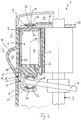
- FIGS. 1 and 2 has an axial piston machine 1 according to the invention, which may be part of a heat recovery system 2 of a motor vehicle, not shown in detail, for example, a shaft 3, which is rotatably connected to a swash plate 4.
- a shaft 3 which is rotatably connected to a swash plate 4.
- Each of these pistons 6 is coupled via a spherical bearing 7 and a sliding block 8 with the swash plate 4 for driving the shaft 3.
- Each cylinder 5 is also associated with an inlet opening 9, which is each covered by a control disk 10.
- This control disk 10 has an eccentrically arranged passage opening 11 and is also rotatably connected to the shaft 3. During each revolution of the control disk 10 whose passage opening 11 passes once each inlet opening 9 of a cylinder 5 and thereby allows access of working fluid in the associated cylinder 5. The working fluid is thereby previously collected in a plenum 12 under pressure, said plenum 12, for example, with a circuit of a heat recovery system 2 is connected.
- the inlet opening 9 is arranged in a cylinder cover 13 and aligned in exactly one rotational position of the control disk 10 with the through hole 11. Between the cylinder cover 13 and the control disk 10, a seal 14 is arranged, which seals the cavity 12 relative to the cylinder 5.
- the spherical bearing 7 is now a multi-part, ie composed of at least two components, whereby its manufacturability can be significantly simplified.
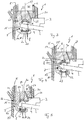
- the spherical bearing 7 according to the FIG. 1 so you can see that this is made in two parts, with a first part 15 and a second part 16, wherein the two parts 15, 16 each have a receptacle 17 (see FIG. FIG. 1 ) or a receiving tray 18 (see. FIGS. 2 to 5 ) exhibit.
- the second part 16 of the spherical bearing 7 can be formed in a cost effective manner as a formed sheet metal bridge, which in particular the production of the spherical bearing 7 is cheaper and easier.
- the spherical bearing 7, in particular the receptacles 17 and the receiving trays 18 can be easily reworked or even processed, whereby not only a higher quality, but also a simpler production is possible.
- the second part 16, in particular the formed sheet metal bridge connected to the first part 15 of the spherical bearing 7 by a press fit, welding, soldering and / or thermal joining.
- At least one of the receptacles 17 or the receiving shells 18 can furthermore have a coating, in particular a polymer coating, a DLC coating or a polytetrafluoroethylene coating (PTFE) or else be nitrided.
- a coating in particular a polymer coating, a DLC coating or a polytetrafluoroethylene coating (PTFE) or else be nitrided.
- PTFE polytetrafluoroethylene coating
- the receiving shells 18 may be formed, for example, of plastic, in particular as a plastic injection molded part, or else be injected into at least one associated receptacle 17 of the spherical bearing 7.
- the spherical bearing 7 is fixedly connected to the associated piston 6, for example caulked with this, welded or soldered, and has a parallel to the piston axis 19 bore 20 into which the respective receiving cup 18 is inserted.
- the respective receiving tray 18 may for example have an extension 21 or nipple, which engages in the bore 20 in a form-fitting manner.
- the receiving tray 18 can be generally positively inserted into a corresponding recess 22 on the first or second part 15, 16 of the spherical bearing 7.
- a screw 23 see. FIG. 4
- a spring 24 see. FIG.
- the sliding block 8 itself may also be made of plastic, in particular of a polymer with polytetrafluoroethylene (PTFE), and thus be on the one hand wear-resistant and on the other hand formed friction.
- PTFE polytetrafluoroethylene
- At least one of the receptacles 17 and the sliding block 8 are shaped such that the sliding block 8 is in an annular contact area 38 in contact with the receptacle 17, corresponding to at least one of the receiving shells 18 and the sliding block 8 in a design with receiving shells 18 be formed so that the sliding block 8 is in an annular contact portion 38 in contact with the receiving tray 18.
- the contact region 38 extends annularly around the piston axis 19 around. In particular, the contact region 38 extends coaxially to the piston axis 19. This reduces torques that are transmitted through the sliding block 8 via the spherical bearing 7 on the piston 6. This reduces again the risk of tilting of the piston 6 in the cylinder 5.
- the contact portion 38 is in an angular range of 20 ° to 70 °, more preferably from 25 ° to 60 ° or even more preferably from 30 ° to 57 ° to the piston axis 19.
- Der Angular range refers to a hemispherical sliding block 8 at an angle 42, measured at a ball center 41 of the sliding block 8, between the piston axis 19 and a connecting line 51 between the ball center 41 and the contact area 38th
- Such a contact region 38 can be achieved, in particular, in that the receptacle 17 or the receiving shell 18 has an inner contour 43 against which the sliding block 8 rests and which is formed from an inner side of a hollow sphere 40 rotating around a circular path 39, wherein the center 44 of FIG Circular path 39 is located on a piston axis 19 and the circular path 39 is located in a plane lying substantially perpendicular to the piston axis 19.
- the circular path 39 has a small radius 45, so that the inner contour 43 deviates only slightly from a spherical shape.
- the radius 46 of the hollow ball 40 is slightly larger than the radius 47 of the hemisphere of the sliding block 8.
- At least one piston 6 has a piston skirt 25 made of a tube, wherein the piston 6 is altogether composed of the piston skirt 25, a piston crown 26 and the spherical bearing 7.
- the individual components 25, 26 and 7 can be thermally joined together, caulked together, glued, welded or soldered.
- the piston skirt 25 and the piston crown 26 may, for example, be formed together from a deep-drawn bowl. Thus, the piston skirt 25 and the piston crown 26 can be formed in one step. A joining of the piston skirt 25 with the piston head 26 is then not necessary. Alternatively or in addition, it can be provided that the piston skirt 25 is formed from a drawn tube, which is formed by cold, warm or hot forming.
- the piston skirt 25 may have a coating, in particular a polymer coating, a DLC coating or a polytetrafluoroethylene coating (PTFE) or be nitrided and thereby on the one hand wear resistant and on the other hand friction trained.
- a coating in particular a polymer coating, a DLC coating or a polytetrafluoroethylene coating (PTFE) or be nitrided and thereby on the one hand wear resistant and on the other hand friction trained.
- the piston skirt 25 is convex or convex, as for example in Fig. 9 is shown. As a result, in particular a jamming of the piston 6 in the cylinder 5 can be reliably avoided.
- the piston skirt 25 may also be concave, as for example in FIG Fig. 10 is shown. As a result, a possible widening of the piston 6 by the joining of the piston skirt 25 with the spherical bearing 7 can be reduced. It can also be combined concave and convex areas, so that both jamming of the piston 6 in the cylinder 5 and a widening of the piston 6 can be avoided when joining.
- the piston skirt 25, as exemplified in Fig. 12 shown, in the axial direction has at least two sections which differ by an outer diameter and / or by an inner diameter.
- the piston skirt 25 is constructed in two parts in the axial direction and that a first part 52 and a second part 54 are connected to each other by means of thermal joining, gluing, welding or soldering.
- Fig. 11 shows, for example, a piston 6 with three sections, which differ in each case by the inner diameter and / or the outer diameter.
- the piston 6 has a non-circular outer contour and the cylinder 5 has a non-circular inner contour formed complementary thereto.
- at least one anti-rotation 32 may be provided which prevents rotation of the piston 6 about its piston axis 19 in the cylinder 5. This is particularly advantageous if the piston 6 has no non-circular outer contour.
- the anti-rotation device 32 may include, for example, a groove 33 and a pin 34 engaging therein, wherein the pin 34 of the spherical bearing 7 and the groove 33 are arranged on a housing 35, or vice versa.
- an anti-rotation device 32 may be provided, which has a groove 33 and a key 48 engaging therein, wherein the key 48 is disposed on the spherical bearing 7 and the groove 33 on the housing 35, or vice versa.
- the groove 33 is formed by at least one guide ring 49 arranged in the housing 35.
- the guide ring 49 may be formed, for example, by a formed sheet metal.
- the guide ring 49 is held by a latching connection 53 in the housing.
- the guide ring 49 may have a collar 50, with which the guide ring 49 is clamped between two housing parts.
- a cylinder liner 27 can be provided in the cylinder 5, which likewise has, for example, a corresponding coating which on the one hand increases the wear resistance and on the other reduces the friction.
- an insertion phase 28 can be provided on the cylinder 5 or on the cylinder liner 27, which is an insertion of the piston 6 in the Cylinder 5 facilitates. This offers the great advantage that such an insertion phase does not have to be provided on the piston head 26.
- At least one spherical bearing 7 may have a vent bore 30, which connects a piston interior 31 with the environment or at least allows pressure equalization with that of the environment outside of the piston 6.
- the axial piston machine 1 described can be part of a heat recovery system 2 of a motor vehicle not drawn otherwise, whereby the efficiency of the motor vehicle can be significantly increased, since the energy is now at least partially usable unused in the environment drained combustion exhaust gases.
- the housing 35 has an outlet opening 36 through which the working medium / exhaust gas can flow into an annular channel 37.
- This annular channel 37 may surround the axial piston machine 1 at least partially annular.
Landscapes
- Engineering & Computer Science (AREA)
- Mechanical Engineering (AREA)
- General Engineering & Computer Science (AREA)
- Manufacturing & Machinery (AREA)
- Pistons, Piston Rings, And Cylinders (AREA)
- Reciprocating Pumps (AREA)
Claims (13)
- Machine à pistons axiaux (1),- avec un arbre (3) qui est relié, solidaire en rotation, à un plateau incliné (4),- avec des cylindres (5) qui sont agencés en anneau autour de l'arbre (3) et de façon coaxiale par rapport à celui-ci et dans lesquels des pistons (6) sont agencés de manière à pouvoir se déplacer en translation,dans lequel chaque piston (6) est couplé au plateau incliné (4) par l'intermédiaire d'un palier à calotte (7) et d'au moins un coulisseau (8),- dans lequel un orifice d'admission (9) est associé à chaque cylindre (5),- avec un plateau de commande (10) comportant une ouverture de passage (11) qui est agencée de manière excentrée et qui, à chaque rotation du plateau de commande (10), balaie une fois chaque orifice d'admission (9) et conduit ainsi du fluide de travail dans le cylindre associé (5),dans lequel- au moins un palier à calotte (7) est réalisé en plusieurs parties,- le palier à calotte (7) est réalisé en deux parties avec une première et une deuxième partie (15, 16), lesquelles deux parties (15, 16) comportent chacune un logement (17) ou une coque de logement (18) pour un coulisseau (8),- le palier à calotte (7) est réalisé en deux parties avec une première et une deuxième partie (15, 16), laquelle première partie (15) est reliée à la jupe de piston (25) et laquelle deuxième partie (16) comporte deux logements (17) ou deux coques de logement (18) pour le coulisseau (8),caractérisée en ce que- la deuxième partie (16) du palier à calotte (7) est réalisée comme un pont en tôle transformé.
- Machine à pistons axiaux selon la revendication 1, caractérisée en ce que le pont en tôle transformé est relié à la première partie (15) du palier à calotte (7) par ajustage serré, soudage, brasage et/ou assemblage thermique.
- Machine à pistons axiaux selon la revendication 1 ou 2, caractérisée en ce qu'au moins un logement (17) ou une coque de logement (18) comporte un revêtement, en particulier un revêtement en polymère, un revêtement au carbone amorphe (DLC) ou un revêtement au polytétrafluoroéthylène (PTFE) ou est nitruré.
- Machine à pistons axiaux selon l'une quelconque des revendications 1 à 3, caractérisée en ce qu'au moins une coque de logement (18) est réalisée en plastique.
- Machine à pistons axiaux selon l'une quelconque des revendications 1 à 4, caractérisée en ce qu'au moins une coque de logement (18) est injectée dans un logement associé (17) du palier à calotte (7).
- Machine à pistons axiaux selon l'une quelconque des revendications 1 à 5, caractérisée en ce que le palier à calotte (7) est relié de manière fixe au piston associé (6) et comporte un trou (20) qui est parallèle à l'axe de piston (19) et dans lequel la coque de logement (18) respective est placée.
- Machine à pistons axiaux selon l'une quelconque des revendications 1 à 6, caractérisée en ce qu'au moins une coque de logement (18) est précontrainte au moyen d'une vis (23) ou d'un ressort (24), en particulier d'un ressort à disques, en particulier à partir du côté de contre-pression, contre le coulisseau associé (8).
- Machine à pistons axiaux selon l'une quelconque des revendications 1 à 7, caractérisée en ce qu'au moins un coulisseau (8) est réalisé en plastique, en particulier en un polymère avec du polytétrafluoroéthylène (PTFE).
- Machine à pistons axiaux selon l'une quelconque des revendications 1 à 8, caractérisée en ce que- au moins l'un des logements (17) et le coulisseau (8) sont formés de telle sorte que le coulisseau (8) est en contact avec le logement (17) dans une zone de contact annulaire (38), ou- au moins l'une des coques de logement (18) et le coulisseau (8) sont formés de telle sorte que le coulisseau (8) est en contact avec la coque de logement (18) dans une zone de contact annulaire (38).
- Machine à pistons axiaux selon la revendication 9, caractérisée en ce que- le coulisseau (8) est réalisé en forme d'hémisphère,- la zone de contact annulaire (38) se trouve dans une zone angulaire comprise entre 30° et 57° par rapport à un axe de piston (19), en se rapportant à un centre de sphère (41) du coulisseau (8).
- Machine à pistons axiaux selon la revendication 9 ou 10, caractérisée en ce que le logement (17) ou la coque de logement (18) présente un contour intérieur (43) qui est formé à partir d'un côté intérieur d'une sphère creuse (40) en rotation autour d'une trajectoire circulaire (39), un centre (44) de la trajectoire circulaire (39) se trouvant sur un axe de piston (19) et la trajectoire circulaire (39) se trouvant dans un plan sensiblement perpendiculaire à l'axe de piston (19).
- Machine à pistons axiaux selon l'une quelconque des revendications 1 à 11, caractérisée en ce qu'au moins un palier à calotte (7) comporte un trou d'aération (30) qui relie un espace intérieur de piston (31) à l'environnement.
- Système de récupération de chaleur (2) dans un véhicule automobile avec une machine à pistons axiaux (1) selon l'une quelconque des revendications 1 à 12.
Applications Claiming Priority (2)
| Application Number | Priority Date | Filing Date | Title |
|---|---|---|---|
| DE102014209892.0A DE102014209892A1 (de) | 2014-05-23 | 2014-05-23 | Axialkolbenmaschine |
| PCT/EP2015/061149 WO2015177231A2 (fr) | 2014-05-23 | 2015-05-20 | Machine à pistons axiaux |
Publications (2)
| Publication Number | Publication Date |
|---|---|
| EP3146208A2 EP3146208A2 (fr) | 2017-03-29 |
| EP3146208B1 true EP3146208B1 (fr) | 2018-08-29 |
Family
ID=53181300
Family Applications (1)
| Application Number | Title | Priority Date | Filing Date |
|---|---|---|---|
| EP15723031.9A Not-in-force EP3146208B1 (fr) | 2014-05-23 | 2015-05-20 | Machine à pistons axiaux |
Country Status (3)
| Country | Link |
|---|---|
| EP (1) | EP3146208B1 (fr) |
| DE (1) | DE102014209892A1 (fr) |
| WO (1) | WO2015177231A2 (fr) |
Families Citing this family (2)
| Publication number | Priority date | Publication date | Assignee | Title |
|---|---|---|---|---|
| DE102016213283A1 (de) * | 2016-07-20 | 2018-01-25 | Mahle International Gmbh | Kolben für eine Axialkolbenmaschine |
| DE102017105610A1 (de) | 2017-03-16 | 2018-09-20 | Volkswagen Aktiengesellschaft | Axialkolbenmotor und Kreisprozessvorrichtung |
Family Cites Families (26)
| Publication number | Priority date | Publication date | Assignee | Title |
|---|---|---|---|---|
| GB118098A (fr) * | 1917-07-19 | |||
| GB863026A (en) * | 1956-05-04 | 1961-03-15 | Edward Athelstan Halford | Improved reciprocatory machines |
| DE1949611A1 (de) * | 1969-10-01 | 1971-04-08 | Linde Ag | Axialkolbenmaschine |
| JPH04179873A (ja) * | 1990-11-09 | 1992-06-26 | Toyota Autom Loom Works Ltd | 揺動斜板式可変容量圧縮機及び揺動斜板とピストンを係留するシューの加工方法 |
| JPH0658248A (ja) * | 1992-08-06 | 1994-03-01 | Toyota Autom Loom Works Ltd | 斜板式圧縮機における回転軸支持構造 |
| US5362154A (en) * | 1993-08-16 | 1994-11-08 | Bernard Wiesen | Pivoting slipper pad bearing and crosshead mechanism |
| DE19620701A1 (de) * | 1995-06-21 | 1997-01-09 | Elektra Beckum Ag | Axialkolbenpumpe, insbesondere für ein Wasser-Hochdruckreinigungsgerät und Verfahren zur Herstellung eines Pumpenkolbens |
| DE19527647A1 (de) * | 1995-07-28 | 1997-01-30 | Linde Ag | Axialkolbenmaschine |
| JPH1047231A (ja) * | 1996-08-02 | 1998-02-17 | Zexel Corp | 可変容量型圧縮機 |
| DE19706066A1 (de) * | 1997-02-17 | 1997-11-20 | Hans Dipl Ing Unger | Kompressor, insbesondere für die Drucklufterzeugung in Kraftfahrzeugen |
| DE19754593A1 (de) * | 1997-12-10 | 1999-07-01 | Kleinedler Peter | Niederhaltering für Axialkolbenmaschinen |
| DE19847159C2 (de) * | 1998-10-13 | 2001-12-06 | Hans Unger | Kompressor zur Erzeugung ölfreier Druckluft |
| DE19955554A1 (de) * | 1998-11-18 | 2000-05-25 | Fkw Hannover Forschungszentrum | Kolbenverdichter |
| KR100302852B1 (ko) * | 1999-03-20 | 2001-10-29 | 신영주 | 압축기용 중공 피스톤 제조방법 |
| JP2001107850A (ja) * | 1999-10-12 | 2001-04-17 | Zexel Valeo Climate Control Corp | 斜板式冷媒圧縮機 |
| DE19954863A1 (de) * | 1999-11-15 | 2001-07-26 | Zexel Valeo Compressor Europe | Kolbenmaschine, insbesondere Verdichter |
| US6736049B2 (en) * | 2000-12-11 | 2004-05-18 | Gilson, Inc. | High pressure low volume pump |
| BR0207848A (pt) * | 2001-03-06 | 2004-06-22 | Honda Motor Co Ltd | Expansor |
| JP4539205B2 (ja) * | 2003-08-21 | 2010-09-08 | 日産自動車株式会社 | 冷媒圧縮機 |
| DE502006002752D1 (de) * | 2005-04-23 | 2009-03-19 | Ixetic Mac Gmbh | Axialkolbenmaschine |
| ES2389450T3 (es) * | 2006-07-29 | 2012-10-26 | Ixetic Bad Homburg Gmbh | Dispositivo para acoplar un pistón a un disco anular |
| US20120079936A1 (en) * | 2009-04-01 | 2012-04-05 | Purdue Research Foundation | Positive displacement machine piston with wavy surface form |
| DE102009019627A1 (de) * | 2009-04-30 | 2010-11-04 | Linde Material Handling Gmbh | Hydrostatische Verdrängermaschine |
| DE102010026360B4 (de) * | 2010-07-07 | 2020-12-03 | Schaeffler Technologies AG & Co. KG | Stößel mit einer Verdrehsicherung |
| DE102010036917A1 (de) | 2010-08-09 | 2012-02-09 | Amovis Gmbh | Axialkolbenmaschine |
| DE102010052508A1 (de) * | 2010-11-26 | 2012-05-31 | Daimler Ag | Abwärmenutzungsvorrichtung |
-
2014
- 2014-05-23 DE DE102014209892.0A patent/DE102014209892A1/de not_active Withdrawn
-
2015
- 2015-05-20 WO PCT/EP2015/061149 patent/WO2015177231A2/fr not_active Ceased
- 2015-05-20 EP EP15723031.9A patent/EP3146208B1/fr not_active Not-in-force
Also Published As
| Publication number | Publication date |
|---|---|
| WO2015177231A3 (fr) | 2016-03-24 |
| EP3146208A2 (fr) | 2017-03-29 |
| DE102014209892A1 (de) | 2015-11-26 |
| WO2015177231A2 (fr) | 2015-11-26 |
Similar Documents
| Publication | Publication Date | Title |
|---|---|---|
| EP1573200B1 (fr) | Machine a piston axiaux | |
| DE69925976T2 (de) | Käfig für Kugellager | |
| EP2342441B1 (fr) | Piston avec canal de refroidissement pour un moteur à combustion interne, avec un élément de fermeture qui ferme le canal de refroidissement | |
| EP0953113B1 (fr) | Compresseur a piston alternatif | |
| EP1636475A1 (fr) | Piston de moteur a combustion interne | |
| WO2016142229A1 (fr) | Machine à pistons axiaux | |
| EP3146208B1 (fr) | Machine à pistons axiaux | |
| DE202006014691U1 (de) | Gleitlageranordnung für eine Welle, sowie Welle und zugeordneter Motor | |
| DE10325914B4 (de) | Kolben für einen Verbrennungsmotor | |
| DE102012207951B4 (de) | Kolben einer Brennkraftmaschine | |
| DE102011051257A1 (de) | Axialkolbenmaschine | |
| WO2005024217A1 (fr) | Piston pour moteur a combustion | |
| DE19528910A1 (de) | Taumelscheibenverdichter | |
| WO2007016891A1 (fr) | Piston pour un moteur a combustion interne et bague de fermeture pour le canal de refroidissement dudit piston | |
| DE19900037A1 (de) | Kraftstoffeinspritzventil | |
| EP1944510A1 (fr) | Machine à piston avec cylindre pivotable | |
| WO2014001256A1 (fr) | Agencement spécial d'un alésage de raccordement d'un canal de refroidissement | |
| DE10059954B4 (de) | Rückschlagventil | |
| WO2005019631A1 (fr) | Piston en plusieurs parties destine a un moteur a combustion interne | |
| DE102010023297A1 (de) | Ölversorgung für eine exzentrisch gelagerte Kurbelwelle | |
| EP3947994B1 (fr) | Procédé d'assemblage de roulement à billes | |
| WO2008080445A1 (fr) | Moteur à pistons hydraulique | |
| DE102010046031A1 (de) | Kompressor mit Kupplungseinrichtung | |
| DE4312498C2 (de) | Förderpumpe | |
| DE102015009568A1 (de) | Brennkraftmaschine sowie Verfahren zum Betreiben einer Brennkraftmaschine |
Legal Events
| Date | Code | Title | Description |
|---|---|---|---|
| STAA | Information on the status of an ep patent application or granted ep patent |
Free format text: STATUS: THE INTERNATIONAL PUBLICATION HAS BEEN MADE |
|
| PUAI | Public reference made under article 153(3) epc to a published international application that has entered the european phase |
Free format text: ORIGINAL CODE: 0009012 |
|
| STAA | Information on the status of an ep patent application or granted ep patent |
Free format text: STATUS: REQUEST FOR EXAMINATION WAS MADE |
|
| 17P | Request for examination filed |
Effective date: 20161121 |
|
| AK | Designated contracting states |
Kind code of ref document: A2 Designated state(s): AL AT BE BG CH CY CZ DE DK EE ES FI FR GB GR HR HU IE IS IT LI LT LU LV MC MK MT NL NO PL PT RO RS SE SI SK SM TR |
|
| AX | Request for extension of the european patent |
Extension state: BA ME |
|
| RIN1 | Information on inventor provided before grant (corrected) |
Inventor name: SCHACHERER, ROLAND Inventor name: LEUTERT, MARKUS Inventor name: BEERENS, CHRISTOPH Inventor name: MUELLER, ROLF Inventor name: SCHNEIDER, FALK Inventor name: BAITINGER, GERT Inventor name: KREISIG, MICHAEL Inventor name: WIESKE, PETER Inventor name: REPGEN, BERTHOLD |
|
| RIN1 | Information on inventor provided before grant (corrected) |
Inventor name: BAITINGER, GERT Inventor name: SCHACHERER, ROLAND Inventor name: BEERENS, CHRISTOPH Inventor name: LEUTERT, MARKUS Inventor name: KREISIG, MICHAEL Inventor name: WIESKE, PETER Inventor name: REPGEN, BERTHOLD Inventor name: MUELLER, ROLF Inventor name: SCHNEIDER, FALK |
|
| DAV | Request for validation of the european patent (deleted) | ||
| DAX | Request for extension of the european patent (deleted) | ||
| GRAP | Despatch of communication of intention to grant a patent |
Free format text: ORIGINAL CODE: EPIDOSNIGR1 |
|
| STAA | Information on the status of an ep patent application or granted ep patent |
Free format text: STATUS: GRANT OF PATENT IS INTENDED |
|
| INTG | Intention to grant announced |
Effective date: 20180507 |
|
| GRAS | Grant fee paid |
Free format text: ORIGINAL CODE: EPIDOSNIGR3 |
|
| GRAA | (expected) grant |
Free format text: ORIGINAL CODE: 0009210 |
|
| STAA | Information on the status of an ep patent application or granted ep patent |
Free format text: STATUS: THE PATENT HAS BEEN GRANTED |
|
| AK | Designated contracting states |
Kind code of ref document: B1 Designated state(s): AL AT BE BG CH CY CZ DE DK EE ES FI FR GB GR HR HU IE IS IT LI LT LU LV MC MK MT NL NO PL PT RO RS SE SI SK SM TR |
|
| REG | Reference to a national code |
Ref country code: GB Ref legal event code: FG4D Free format text: NOT ENGLISH |
|
| REG | Reference to a national code |
Ref country code: CH Ref legal event code: EP |
|
| REG | Reference to a national code |
Ref country code: AT Ref legal event code: REF Ref document number: 1035440 Country of ref document: AT Kind code of ref document: T Effective date: 20180915 |
|
| REG | Reference to a national code |
Ref country code: IE Ref legal event code: FG4D Free format text: LANGUAGE OF EP DOCUMENT: GERMAN |
|
| REG | Reference to a national code |
Ref country code: DE Ref legal event code: R096 Ref document number: 502015005685 Country of ref document: DE |
|
| REG | Reference to a national code |
Ref country code: NL Ref legal event code: MP Effective date: 20180829 |
|
| REG | Reference to a national code |
Ref country code: LT Ref legal event code: MG4D |
|
| PG25 | Lapsed in a contracting state [announced via postgrant information from national office to epo] |
Ref country code: FI Free format text: LAPSE BECAUSE OF FAILURE TO SUBMIT A TRANSLATION OF THE DESCRIPTION OR TO PAY THE FEE WITHIN THE PRESCRIBED TIME-LIMIT Effective date: 20180829 Ref country code: RS Free format text: LAPSE BECAUSE OF FAILURE TO SUBMIT A TRANSLATION OF THE DESCRIPTION OR TO PAY THE FEE WITHIN THE PRESCRIBED TIME-LIMIT Effective date: 20180829 Ref country code: IS Free format text: LAPSE BECAUSE OF FAILURE TO SUBMIT A TRANSLATION OF THE DESCRIPTION OR TO PAY THE FEE WITHIN THE PRESCRIBED TIME-LIMIT Effective date: 20181229 Ref country code: NO Free format text: LAPSE BECAUSE OF FAILURE TO SUBMIT A TRANSLATION OF THE DESCRIPTION OR TO PAY THE FEE WITHIN THE PRESCRIBED TIME-LIMIT Effective date: 20181129 Ref country code: NL Free format text: LAPSE BECAUSE OF FAILURE TO SUBMIT A TRANSLATION OF THE DESCRIPTION OR TO PAY THE FEE WITHIN THE PRESCRIBED TIME-LIMIT Effective date: 20180829 Ref country code: BG Free format text: LAPSE BECAUSE OF FAILURE TO SUBMIT A TRANSLATION OF THE DESCRIPTION OR TO PAY THE FEE WITHIN THE PRESCRIBED TIME-LIMIT Effective date: 20181129 Ref country code: SE Free format text: LAPSE BECAUSE OF FAILURE TO SUBMIT A TRANSLATION OF THE DESCRIPTION OR TO PAY THE FEE WITHIN THE PRESCRIBED TIME-LIMIT Effective date: 20180829 Ref country code: GR Free format text: LAPSE BECAUSE OF FAILURE TO SUBMIT A TRANSLATION OF THE DESCRIPTION OR TO PAY THE FEE WITHIN THE PRESCRIBED TIME-LIMIT Effective date: 20181130 Ref country code: LT Free format text: LAPSE BECAUSE OF FAILURE TO SUBMIT A TRANSLATION OF THE DESCRIPTION OR TO PAY THE FEE WITHIN THE PRESCRIBED TIME-LIMIT Effective date: 20180829 |
|
| PG25 | Lapsed in a contracting state [announced via postgrant information from national office to epo] |
Ref country code: AL Free format text: LAPSE BECAUSE OF FAILURE TO SUBMIT A TRANSLATION OF THE DESCRIPTION OR TO PAY THE FEE WITHIN THE PRESCRIBED TIME-LIMIT Effective date: 20180829 Ref country code: LV Free format text: LAPSE BECAUSE OF FAILURE TO SUBMIT A TRANSLATION OF THE DESCRIPTION OR TO PAY THE FEE WITHIN THE PRESCRIBED TIME-LIMIT Effective date: 20180829 Ref country code: HR Free format text: LAPSE BECAUSE OF FAILURE TO SUBMIT A TRANSLATION OF THE DESCRIPTION OR TO PAY THE FEE WITHIN THE PRESCRIBED TIME-LIMIT Effective date: 20180829 |
|
| PG25 | Lapsed in a contracting state [announced via postgrant information from national office to epo] |
Ref country code: ES Free format text: LAPSE BECAUSE OF FAILURE TO SUBMIT A TRANSLATION OF THE DESCRIPTION OR TO PAY THE FEE WITHIN THE PRESCRIBED TIME-LIMIT Effective date: 20180829 Ref country code: PL Free format text: LAPSE BECAUSE OF FAILURE TO SUBMIT A TRANSLATION OF THE DESCRIPTION OR TO PAY THE FEE WITHIN THE PRESCRIBED TIME-LIMIT Effective date: 20180829 Ref country code: RO Free format text: LAPSE BECAUSE OF FAILURE TO SUBMIT A TRANSLATION OF THE DESCRIPTION OR TO PAY THE FEE WITHIN THE PRESCRIBED TIME-LIMIT Effective date: 20180829 Ref country code: CZ Free format text: LAPSE BECAUSE OF FAILURE TO SUBMIT A TRANSLATION OF THE DESCRIPTION OR TO PAY THE FEE WITHIN THE PRESCRIBED TIME-LIMIT Effective date: 20180829 Ref country code: IT Free format text: LAPSE BECAUSE OF FAILURE TO SUBMIT A TRANSLATION OF THE DESCRIPTION OR TO PAY THE FEE WITHIN THE PRESCRIBED TIME-LIMIT Effective date: 20180829 Ref country code: EE Free format text: LAPSE BECAUSE OF FAILURE TO SUBMIT A TRANSLATION OF THE DESCRIPTION OR TO PAY THE FEE WITHIN THE PRESCRIBED TIME-LIMIT Effective date: 20180829 |
|
| PG25 | Lapsed in a contracting state [announced via postgrant information from national office to epo] |
Ref country code: DK Free format text: LAPSE BECAUSE OF FAILURE TO SUBMIT A TRANSLATION OF THE DESCRIPTION OR TO PAY THE FEE WITHIN THE PRESCRIBED TIME-LIMIT Effective date: 20180829 Ref country code: SM Free format text: LAPSE BECAUSE OF FAILURE TO SUBMIT A TRANSLATION OF THE DESCRIPTION OR TO PAY THE FEE WITHIN THE PRESCRIBED TIME-LIMIT Effective date: 20180829 Ref country code: SK Free format text: LAPSE BECAUSE OF FAILURE TO SUBMIT A TRANSLATION OF THE DESCRIPTION OR TO PAY THE FEE WITHIN THE PRESCRIBED TIME-LIMIT Effective date: 20180829 |
|
| REG | Reference to a national code |
Ref country code: DE Ref legal event code: R097 Ref document number: 502015005685 Country of ref document: DE |
|
| PLBE | No opposition filed within time limit |
Free format text: ORIGINAL CODE: 0009261 |
|
| STAA | Information on the status of an ep patent application or granted ep patent |
Free format text: STATUS: NO OPPOSITION FILED WITHIN TIME LIMIT |
|
| 26N | No opposition filed |
Effective date: 20190531 |
|
| PG25 | Lapsed in a contracting state [announced via postgrant information from national office to epo] |
Ref country code: SI Free format text: LAPSE BECAUSE OF FAILURE TO SUBMIT A TRANSLATION OF THE DESCRIPTION OR TO PAY THE FEE WITHIN THE PRESCRIBED TIME-LIMIT Effective date: 20180829 |
|
| REG | Reference to a national code |
Ref country code: CH Ref legal event code: PL |
|
| GBPC | Gb: european patent ceased through non-payment of renewal fee |
Effective date: 20190520 |
|
| PG25 | Lapsed in a contracting state [announced via postgrant information from national office to epo] |
Ref country code: MC Free format text: LAPSE BECAUSE OF FAILURE TO SUBMIT A TRANSLATION OF THE DESCRIPTION OR TO PAY THE FEE WITHIN THE PRESCRIBED TIME-LIMIT Effective date: 20180829 Ref country code: CH Free format text: LAPSE BECAUSE OF NON-PAYMENT OF DUE FEES Effective date: 20190531 Ref country code: LI Free format text: LAPSE BECAUSE OF NON-PAYMENT OF DUE FEES Effective date: 20190531 |
|
| REG | Reference to a national code |
Ref country code: BE Ref legal event code: MM Effective date: 20190531 |
|
| PG25 | Lapsed in a contracting state [announced via postgrant information from national office to epo] |
Ref country code: LU Free format text: LAPSE BECAUSE OF NON-PAYMENT OF DUE FEES Effective date: 20190520 |
|
| PG25 | Lapsed in a contracting state [announced via postgrant information from national office to epo] |
Ref country code: TR Free format text: LAPSE BECAUSE OF FAILURE TO SUBMIT A TRANSLATION OF THE DESCRIPTION OR TO PAY THE FEE WITHIN THE PRESCRIBED TIME-LIMIT Effective date: 20180829 |
|
| PG25 | Lapsed in a contracting state [announced via postgrant information from national office to epo] |
Ref country code: IE Free format text: LAPSE BECAUSE OF NON-PAYMENT OF DUE FEES Effective date: 20190520 Ref country code: GB Free format text: LAPSE BECAUSE OF NON-PAYMENT OF DUE FEES Effective date: 20190520 |
|
| PG25 | Lapsed in a contracting state [announced via postgrant information from national office to epo] |
Ref country code: BE Free format text: LAPSE BECAUSE OF NON-PAYMENT OF DUE FEES Effective date: 20190531 |
|
| PG25 | Lapsed in a contracting state [announced via postgrant information from national office to epo] |
Ref country code: FR Free format text: LAPSE BECAUSE OF NON-PAYMENT OF DUE FEES Effective date: 20190531 Ref country code: PT Free format text: LAPSE BECAUSE OF FAILURE TO SUBMIT A TRANSLATION OF THE DESCRIPTION OR TO PAY THE FEE WITHIN THE PRESCRIBED TIME-LIMIT Effective date: 20181229 |
|
| PG25 | Lapsed in a contracting state [announced via postgrant information from national office to epo] |
Ref country code: CY Free format text: LAPSE BECAUSE OF FAILURE TO SUBMIT A TRANSLATION OF THE DESCRIPTION OR TO PAY THE FEE WITHIN THE PRESCRIBED TIME-LIMIT Effective date: 20180829 |
|
| REG | Reference to a national code |
Ref country code: AT Ref legal event code: MM01 Ref document number: 1035440 Country of ref document: AT Kind code of ref document: T Effective date: 20200520 |
|
| PG25 | Lapsed in a contracting state [announced via postgrant information from national office to epo] |
Ref country code: HU Free format text: LAPSE BECAUSE OF FAILURE TO SUBMIT A TRANSLATION OF THE DESCRIPTION OR TO PAY THE FEE WITHIN THE PRESCRIBED TIME-LIMIT; INVALID AB INITIO Effective date: 20150520 Ref country code: MT Free format text: LAPSE BECAUSE OF FAILURE TO SUBMIT A TRANSLATION OF THE DESCRIPTION OR TO PAY THE FEE WITHIN THE PRESCRIBED TIME-LIMIT Effective date: 20180829 |
|
| PGFP | Annual fee paid to national office [announced via postgrant information from national office to epo] |
Ref country code: DE Payment date: 20210527 Year of fee payment: 7 |
|
| PG25 | Lapsed in a contracting state [announced via postgrant information from national office to epo] |
Ref country code: AT Free format text: LAPSE BECAUSE OF NON-PAYMENT OF DUE FEES Effective date: 20200520 |
|
| PG25 | Lapsed in a contracting state [announced via postgrant information from national office to epo] |
Ref country code: MK Free format text: LAPSE BECAUSE OF FAILURE TO SUBMIT A TRANSLATION OF THE DESCRIPTION OR TO PAY THE FEE WITHIN THE PRESCRIBED TIME-LIMIT Effective date: 20180829 |
|
| REG | Reference to a national code |
Ref country code: DE Ref legal event code: R119 Ref document number: 502015005685 Country of ref document: DE |
|
| PG25 | Lapsed in a contracting state [announced via postgrant information from national office to epo] |
Ref country code: DE Free format text: LAPSE BECAUSE OF NON-PAYMENT OF DUE FEES Effective date: 20221201 |