EP3146224B1 - Agencement de volant d'inertie - Google Patents
Agencement de volant d'inertie Download PDFInfo
- Publication number
- EP3146224B1 EP3146224B1 EP15730213.4A EP15730213A EP3146224B1 EP 3146224 B1 EP3146224 B1 EP 3146224B1 EP 15730213 A EP15730213 A EP 15730213A EP 3146224 B1 EP3146224 B1 EP 3146224B1
- Authority
- EP
- European Patent Office
- Prior art keywords
- flywheel
- shaft
- magnet
- magnets
- rotating
- Prior art date
- Legal status (The legal status is an assumption and is not a legal conclusion. Google has not performed a legal analysis and makes no representation as to the accuracy of the status listed.)
- Active
Links
Images




Classifications
-
- F—MECHANICAL ENGINEERING; LIGHTING; HEATING; WEAPONS; BLASTING
- F16—ENGINEERING ELEMENTS AND UNITS; GENERAL MEASURES FOR PRODUCING AND MAINTAINING EFFECTIVE FUNCTIONING OF MACHINES OR INSTALLATIONS; THERMAL INSULATION IN GENERAL
- F16F—SPRINGS; SHOCK-ABSORBERS; MEANS FOR DAMPING VIBRATION
- F16F15/00—Suppression of vibrations in systems; Means or arrangements for avoiding or reducing out-of-balance forces, e.g. due to motion
- F16F15/30—Flywheels
- F16F15/315—Flywheels characterised by their supporting arrangement, e.g. mountings, cages, securing inertia member to shaft
- F16F15/3156—Arrangement of the bearings
-
- F—MECHANICAL ENGINEERING; LIGHTING; HEATING; WEAPONS; BLASTING
- F16—ENGINEERING ELEMENTS AND UNITS; GENERAL MEASURES FOR PRODUCING AND MAINTAINING EFFECTIVE FUNCTIONING OF MACHINES OR INSTALLATIONS; THERMAL INSULATION IN GENERAL
- F16C—SHAFTS; FLEXIBLE SHAFTS; ELEMENTS OR CRANKSHAFT MECHANISMS; ROTARY BODIES OTHER THAN GEARING ELEMENTS; BEARINGS
- F16C39/00—Relieving load on bearings
- F16C39/06—Relieving load on bearings using magnetic means
- F16C39/063—Permanent magnets
-
- F—MECHANICAL ENGINEERING; LIGHTING; HEATING; WEAPONS; BLASTING
- F16—ENGINEERING ELEMENTS AND UNITS; GENERAL MEASURES FOR PRODUCING AND MAINTAINING EFFECTIVE FUNCTIONING OF MACHINES OR INSTALLATIONS; THERMAL INSULATION IN GENERAL
- F16C—SHAFTS; FLEXIBLE SHAFTS; ELEMENTS OR CRANKSHAFT MECHANISMS; ROTARY BODIES OTHER THAN GEARING ELEMENTS; BEARINGS
- F16C32/00—Bearings not otherwise provided for
- F16C32/04—Bearings not otherwise provided for using magnetic or electric supporting means
- F16C32/0406—Magnetic bearings
- F16C32/0408—Passive magnetic bearings
- F16C32/0423—Passive magnetic bearings with permanent magnets on both parts repelling each other
- F16C32/0429—Passive magnetic bearings with permanent magnets on both parts repelling each other for both radial and axial load, e.g. conical magnets
- F16C32/0431—Passive magnetic bearings with permanent magnets on both parts repelling each other for both radial and axial load, e.g. conical magnets with bearings for axial load combined with bearings for radial load
-
- F—MECHANICAL ENGINEERING; LIGHTING; HEATING; WEAPONS; BLASTING
- F16—ENGINEERING ELEMENTS AND UNITS; GENERAL MEASURES FOR PRODUCING AND MAINTAINING EFFECTIVE FUNCTIONING OF MACHINES OR INSTALLATIONS; THERMAL INSULATION IN GENERAL
- F16F—SPRINGS; SHOCK-ABSORBERS; MEANS FOR DAMPING VIBRATION
- F16F15/00—Suppression of vibrations in systems; Means or arrangements for avoiding or reducing out-of-balance forces, e.g. due to motion
- F16F15/30—Flywheels
-
- H—ELECTRICITY
- H02—GENERATION; CONVERSION OR DISTRIBUTION OF ELECTRIC POWER
- H02K—DYNAMO-ELECTRIC MACHINES
- H02K7/00—Arrangements for handling mechanical energy structurally associated with dynamo-electric machines, e.g. structural association with mechanical driving motors or auxiliary dynamo-electric machines
- H02K7/02—Additional mass for increasing inertia, e.g. flywheels
- H02K7/025—Additional mass for increasing inertia, e.g. flywheels for power storage
-
- F—MECHANICAL ENGINEERING; LIGHTING; HEATING; WEAPONS; BLASTING
- F16—ENGINEERING ELEMENTS AND UNITS; GENERAL MEASURES FOR PRODUCING AND MAINTAINING EFFECTIVE FUNCTIONING OF MACHINES OR INSTALLATIONS; THERMAL INSULATION IN GENERAL
- F16C—SHAFTS; FLEXIBLE SHAFTS; ELEMENTS OR CRANKSHAFT MECHANISMS; ROTARY BODIES OTHER THAN GEARING ELEMENTS; BEARINGS
- F16C2361/00—Apparatus or articles in engineering in general
- F16C2361/55—Flywheel systems
-
- F—MECHANICAL ENGINEERING; LIGHTING; HEATING; WEAPONS; BLASTING
- F16—ENGINEERING ELEMENTS AND UNITS; GENERAL MEASURES FOR PRODUCING AND MAINTAINING EFFECTIVE FUNCTIONING OF MACHINES OR INSTALLATIONS; THERMAL INSULATION IN GENERAL
- F16F—SPRINGS; SHOCK-ABSORBERS; MEANS FOR DAMPING VIBRATION
- F16F15/00—Suppression of vibrations in systems; Means or arrangements for avoiding or reducing out-of-balance forces, e.g. due to motion
- F16F15/30—Flywheels
- F16F15/31—Flywheels characterised by means for varying the moment of inertia
-
- Y—GENERAL TAGGING OF NEW TECHNOLOGICAL DEVELOPMENTS; GENERAL TAGGING OF CROSS-SECTIONAL TECHNOLOGIES SPANNING OVER SEVERAL SECTIONS OF THE IPC; TECHNICAL SUBJECTS COVERED BY FORMER USPC CROSS-REFERENCE ART COLLECTIONS [XRACs] AND DIGESTS
- Y02—TECHNOLOGIES OR APPLICATIONS FOR MITIGATION OR ADAPTATION AGAINST CLIMATE CHANGE
- Y02E—REDUCTION OF GREENHOUSE GAS [GHG] EMISSIONS, RELATED TO ENERGY GENERATION, TRANSMISSION OR DISTRIBUTION
- Y02E60/00—Enabling technologies; Technologies with a potential or indirect contribution to GHG emissions mitigation
- Y02E60/16—Mechanical energy storage, e.g. flywheels or pressurised fluids
Definitions
- flywheels can be very efficient and can store great amounts of energy in very confined spaces.
- One of the problems with storing great amounts of energy in very confined spaces is the health and safety implications. If something goes wrong with a flywheel which is constructed of steel or highly compacted composite materials such as fibre glass or carbon fibre, then the dangers from debris can be considerable therefore in an effort to reduce any risk to life or property, steel or solid composite flywheels are usually encased in a strong steel tube and buried into the ground.
- flywheel An alternative to this sort of flywheel is a flywheel containing fluid.
- the flywheel is hollow and lightweight and may be driven up to its operating speed before fluid is added to thereby increase the mass of the flywheel. If energy is available to be stored in the flywheel the operating speed of the flywheel can be maintained while the addition of fluid increases the mass of the flywheel.
- One advantage of this sort of flywheel can be, in the event of a defect in the structure of the flywheel or a component such as a bearing if the flywheel breaks up the majority of the mass may be contained within a surrounding containment tank or bund, where the strength of the containment tank may be sufficient to contain the debris and avoid the necessity to bury the tank in to the ground.
- the containment tank may be provided with a vacuum pump in order to evacuate the tank of air, or to at least partially evacuate and/or reduce the amount of air contained within the tank. This results in lower air resistance and so the flywheel is able to rotate for longer.
- the reduced health and safety risks of a flywheel containing fluid make them more suitable to domestic or commercial environments; they can also be used in many industrial applications.
- a problem with a flywheel containing fluid is that during its operating cycle, the velocity and mass of the flywheel may change depending on how much fluid is present within the flywheel. This means that there will be different stresses and strains applied to the supporting bearings at different times during the operating cycle of the flywheel containing fluid.
- US6630761 (Gabrys Christopher ) is considered to be the closest prior art and discloses a combination mechanical and magnetic support system for a flywheel power supply for storing and retrieving energy.
- the power supply includes a flywheel that spins about an axis of rotation inside an evacuated chamber for storing and retrieving the energy.
- FR2356044 (Battelle Development) discloses a magnetic suspension unit with a magnetic bearing for the frictionless suspension of a rotor relative to a housing and is designed for an inertial energy storage machine.
- the rotor is a disc-shaped flywheel having its circumferential made from magnetisable material.
- the flywheel incorporates a permanent magnet ring magnetised parallel to the wheel's axle.
- the base has a second permanent magnet ring. The two magnets repel one another so that it floats in the chamber.
- WO2012/127194 Liverpool Renewable Energy Research discloses an energy storage system comprising one or more variable inertia flywheels and fluid feeding means, whereby the inertia of the, or each, flywheel is varied by fluid.
- US7126243 discloses a rotator supporting mechanism in a microgravitational rotating apparatus comprises a magnetic bearing of the rotator so as to effect a vibration control.
- a rotary shaft has its upper end inserted into a recessed portion and its lower end inserted into a recessed portion and connected to a motor. Both ends of the rotary shaft 30 are supported by a magnetic force.
- JP S58217840 discloses a protective shaft mounted on an upper shaft end of a flywheel.
- the protective shaft is forged of Al, plastics, or the like and is easily replaced.
- the second protective bearing is disposed on the outer peripheral portion of a magnetic bearing on the rotation side, and is fixed to the interior of a receptacle through a bearing support. When excessive vibration is generated, the protective shaft is brought into contact with a protective bearing to be broken.
- the present invention is directed to a flywheel system and control mechanism as defines in the enclosed independent claims. Preferred features are set out in the sub-claims.
- a flywheel comprising a rotatable shaft, at least one end of the rotatable shaft being provided with a recess and two magnets, wherein the flywheel is provided with support means, the support means comprising:
- the magnets may be arranged so that the two magnets on the shaft are attracted to, or repelled from, the respective first or second arrangement of magnets.
- the attraction or repulsion depends on the orientation of the magnets with respect to the shaft and arrangement employed.
- the first arrangement comprises a toroidal magnets and wherein the first shaft magnet is arranged coaxially with the magnet of the first arrangement and substantially therein, and more preferably, the first shaft magnet is toroidal and has a smaller diameter that the toroidal magnet of the first arrangement.
- the shaft magnet being smaller than the other magnet of the first arrangement allows for the shaft magnet to be positioned within the other magnet. This allows for any movement of the shaft magnet in a horizontal direction to be countered by the other magnet to keep the shaft centred.
- the second arrangement comprises a toroidal magnet and the second shaft magnet is arranged coaxially with the magnet of the second arrangement and adjacent thereto, and more advantageously, the second shaft magnet is toroidal and has a diameter substantially the same as the toroidal magnet of the second arrangement and is positioned above the magnet of the second arrangement. Positioning one magnet above the other allows for vertical stabilization of the shaft because movement of one magnet will cause the magnetic fields and/or gravity to interfere with the field of the moved magnet, thereby providing vertical stabilization by the correction of movement in the fields to re-establish an equilibrium position.
- the stabilisation arrangement in the form of support means allows for movement of the flywheel shaft in a vertical and horizontal direction to be controlled using two coaxial arrangements of magnets: the first comprising one on top of the other to allow the vertical position of the shaft to be controlled; and the second having one
- both ends of the rotatable shaft comprise a two magnets and respective associated support means. This allows either or both end to be adjusted to keep the shaft stable.
- top and bottom pins are provided to be received within the recesses of the shaft. Positioning the pins within the recesses reduces the risk of the shaft falling and it allows for light touches between the inside of the shaft recesses and pins to assist with the stabilisation.
- the pins are electrically conductive, which allows them to be used as switches for monitoring the position of the shaft relative to the pins.
- the shaft further comprises magnetic bearings and a framework is provided with respective magnetic bearings to levitate the shaft from the framework.
- the framework provides a fixed location for the shaft to levitate relative to and the magnetic bearings reduce friction in the system, thereby allowing the flywheel to rotate for long periods of time.
- the vertical position of the support means is adjustable to alter the vertical position of the shaft. This may include moving the pins accordingly so that they assist with the stabilisation of the shaft. By moving the vertical position of the shaft, the friction in the arrangement can be reduced and the flywheel can be more readily controlled.
- a computer may be provided to monitor the position of the shaft and to adjust the support means to alter the vertical height of the shaft. Allowing a computer to monitor and adjust the position of the support means and the shaft of the flywheel allows for automated responses to changes in the shaft position and balance.
- the shaft is provided with an electrical contact in its recess, the method comprising the steps of monitoring the electrical flow through at least one pin and adjusting the vertical position of the shaft using a stepper motor until the flow ceases, and adjusting the vertical position of the shaft until the electrical contact is re-established.
- This allows the position of the shaft relative to the pins to be adjusted so that the frictional contact is reduced, thereby allowing for longer rotation of the flywheel.
- the friction can be monitored and controlled to keep it relatively low.
- the rotation of the shaft can be reduced by increasing the friction between the pins and the shaft.
- the top and bottom of the vertically aligned rotating centre shaft may be supported by respective centralising pins; the centralising pins may act as a pair of switches to enable a computer control means to make accurate adjustments to the position of the array of permanent magnets and the position of the centralising pins.
- the top and bottom centralising pins may be constantly adjusted independently height-wise, or vertically, and almost simultaneously by the computer control means to apply a controlled pressure to both ends of the rotating centre shaft of a flywheel containing fluid to maintain stability and reduce undesirable vibrations in a flywheel containing fluid.
- One object of the present invention is to provide a vertical array of permanent magnets for the support and stabilisation of a flywheel containing fluid, where the vertical array of permanent magnets is situated at or near to the top of a vertically aligned centre shaft of a flywheel containing fluid and at least one magnet of the said vertical array is vertically adjustable.
- Another object of the present invention is to provide a vertical array of permanent magnets for the support and stabilisation of a flywheel containing fluid, where the vertical array of permanent magnets is situated at or near to the bottom of a vertically aligned centre shaft of a flywheel containing fluid and at least one magnet of the said vertical array is vertically adjustable.
- Another object of the present invention is to provide a horizontal array of permanent magnets for the support and stabilisation of a flywheel containing fluid, where the said horizontal array of permanent magnets is situated at or near to the top and/or bottom of a vertically aligned centre shaft of a flywheel containing fluid and at least one magnet of the said horizontal array is vertically adjustable.
- an object of the present invention is to provide a horizontal array of permanent magnets for the support and stabilisation of a flywheel containing fluid, where the said horizontal array of permanent magnets is situated at or near to the top and/or bottom of a vertically aligned centre shaft of a flywheel containing fluid and at least one magnet of the said horizontal array is securely fixed and not adjustable.
- Another object of the present invention is to provide a centralising pin for the support and stabilisation of a flywheel containing fluid, where the said centralising pin is situated at the top and/or bottom of a vertically aligned centre shaft of a flywheel containing fluid.
- Another object of the present invention is to provide a centralising pin for the support and stabilisation of a flywheel containing fluid, where the said centralising pin may be shaped to a pointed cone at one end of the centralising pin.
- Another object of the present invention is to provide a centralising pin for the support and stabilisation of a flywheel containing fluid, where the said centralising pin may be shaped with a radius at the tip of the pointed cone at one end of the centralising pin.
- the strength of all permanent magnets within the present invention is fixed and the strength of the interacting magnetic fields may be adjusted by adjusting the position of any or all of the magnetic supporting means and thereby adjusting the position of any or all of the magnets within any of the magnetic arrays of the present invention.
- the strength of all permanent magnets within the present invention is fixed and the strength of the interacting magnetic fields may be adjusted by adjusting the position of any or all of the magnetic supporting means furthermore the position of any or all of the said supporting means may be controlled by the computer control means of the present invention.
- Another object of the present invention is to provide a mechanical thrust bearing that may be separated in to two halves, where one half is securely attached to the vertically adjustable rotating centre shaft of the flywheel containing fluid and the other half is securely attached to a fixed means which is rigidly fixed into position.
- one or more surface areas of the internal cone of the recess of the rotating centre shaft may come into physical contact with the adjustable centralising pin.
- an object of the present invention is to provide an adjustable rotating centre shaft and an adjustable centralising pin wherein the vertical adjustment of the centralising pin and or the vertical adjustment of the rotating centre shaft may make or break physical contact between the said rotating centre shaft and the said centralising pin and wherein the making and or breaking contact may be used to provide a pressure on pressure sensor that may provide a signal to the computer control means.
- the said pressure sensor may be for example a piezoelectric crystal transducer with an output signal proportional to the pressure being applied.
- the operating cycle of the flywheel energy storage system may be divided into three distinct period of time.
- the computer control means is used to measure the speed and mass of the flywheel and measure the energy available to drive the motor and thereby drive the flywheel.
- the computer control means When it is determined by the computer control means that sufficient energy is available for the flywheel energy storage system to begin or continue its cycle energy is transferred to the drive motor and the speed of the flywheel may be increased until the flywheel reaches a predetermined speed. At the predetermined speed the computer control means provide control signals to allow the operation of the fluid pumping means to transfer fluid from an external reservoir to the peripheral reservoir chambers located in the periphery of the flywheel. When fluid is present in the inside reservoir the fluid transfer means transfers fluid from the inside reservoir to the inside of the flywheel.
- the computer control means maintains the power to the drive motor and the fluid to the inside reservoir until the flywheel reaches a predetermined speed and mass.
- the computer control means may monitor the availability of energy to be stored and the demand of energy as required by the consumer.
- the computer control means may adjust the position of the vertical array of permanent magnets in order to raise the rotating centre shaft and the flywheel, by raising the rotating centre shaft the rotating part and the non-rotating part of at least one thrust bearing may become disconnected, this is known as the second period of the operating cycle.
- the computer control means may be used to precisely adjust the position of the top and bottom centralising pins so that both centralising pins may be just touching the rotating centre shaft.
- the pressure applied by both centralising pins to the rotating centre shaft may be adjusted and controlled by the computer control means.
- the centralising pins may be used as switches to provide the computer control means with a signal to allow the computer control means to determine when the centralising pins are in contact with the rotating centre shaft.
- the adjustment of the vertical array of magnets and the coordinated adjustment of the centralising pins may also be used to adjust the vertical position of the rotating centre shaft so that the rotating centre shaft is in the optimum position to take advantage of the horizontal array of permanent magnets and thereby reduce any horizontal movement in the rotating centre shaft.
- the computer control means changing the position of the vertical array of magnets so that the rotating centre shaft may be lowered to enable the rotating part and the none rotating part of a one or more thrust bearings to be connected and thereby support the weight of the rotating centre shaft and the flywheel containing fluid.
- the position of the centralising pins may be adjusted in a vertical direction
- the computer control means may be used to provide a plurality of electrical signals to drive a stepper motor in incremental steps, the stepper motor may be used to drive a series of timing belts and pulleys.
- the computer controlled adjustment of the stepper motor and pulleys may be used to accurately adjust the position of the centralising pins.
- Figures 1 and 2 show how there is provided a containment tank 1, for housing one or more flywheels 6.
- the said containment tank 1, may be attached to a vacuum pump 11 to at least partially evacuate the containment tank 1.
- the flywheel 6, is provided with a cavity 49, for retaining fluid, the said flywheel 6, may be physically attached to a rotating centre shaft 7, by a plurality of horizontal baffles 8, the said horizontal baffles 8, may be supported by vertical baffles 9.
- the horizontal baffles 8, may be provided with holes 52, to allow fluid to pass freely from one compartment of the flywheel 6, to another.
- the vertical baffles 9, may be provided with holes 53, to allow fluid to pass freely from one compartment of the flywheel 6, to another.
- Figure 2 shows how the rotating centre shaft 7, may be securely connected to a top thrust bearing rotating part 25, and a bottom thrust bearing rotating part 41.
- Figure 2 also shows how the bottom thrust bearing none-rotating part 42, may be supported by a bottom thrust bearing support means 43, and the top thrust bearing none-rotating part 26, may be supported by a top thrust bearing support means 27.
- Figure 2 shows how the top thrust bearing none-rotating part 26, and the bottom thrust bearing none-rotating part 42, may not be physically connected to the rotating centre shaft 7.
- Figure 2 shows how a combined motor and or generator and or turbine unit 10, may be connected to the rotating centre shaft 7.
- Figure 2 shows how a fluid reservoir 45, may be situated below the flywheel 6, and a fluid transfer means 46, may be attached to the flywheel 6, the fluid transfer means 46, may transfer fluid from the fluid reservoir 45, into and out of the interior of the flywheel 6.
- Figure 3 shows how a vertical array of permanent magnets may be situated at or near to the top end of the vertically aligned rotating centre shaft 7, where the rotating magnet 15, may be physically connected to the rotating centre shaft 7, and supported by a magnet support means 16.
- Figure 3 shows how a top vertical array of magnets may contain a non-rotating permanent magnet 17, and the said non-rotating permanent magnet 17, which may be supported by a vertically adjustable support means 18.
- Figure 3 shows how a horizontal array of permanent magnets may be situated at or near to the top end of the rotating centre shaft 7.
- the said horizontal array of permanent magnets may contain a rotating magnet 20, and a none-rotating magnet 22.
- the said none-rotating magnet 22, may be supported by a vertically adjustable magnet support means 23.
- the none-rotating magnet 22, and the magnet support means 23, may be fixed and not adjustable.
- Figure 3 shows how a top centralising pin 12, may be situated at the top of the rotating centre shaft 7.
- the conical, or tapered, tip 50, of the centralising pin 12, may be seated in the recess 51, of the rotating centre shaft 7.
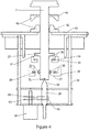
- Figure 4 also shows how a vertical array of permanent magnets may be situated at or near to the bottom end of the vertically aligned rotating centre shaft 7, where the rotating magnet 31, may be physically connected to the rotating centre shaft 7, and supported by a magnet support means 32.
- Figure 4 shows how a bottom vertical array of permanent magnets may contain a non-rotating magnet 33, and the said magnet may be supported by a vertically adjustable support means 34.
- Figure 4 shows how a horizontal array of permanent magnets may be situated at or near to the bottom end of the rotating centre shaft 7.
- the said horizontal array may consist of a rotating magnet 36, and a none-rotating magnet 38.
- the rotating magnet 36 may be supported by a support means 37, and the none-rotating magnet 38 may be supported by a support means 39.
- the said non-rotating magnet 38 may be supported by a vertically adjustable support means 39.
- the none-rotating magnet 38, and the magnet support means 39 may be fixed and not adjustable.
- Figure 4 shows how a bottom centralising pin 28, may be situated at the bottom end of the rotating centre shaft 7.
- the conical tip 50 may be positioned to fit neatly into the recess 51, of the rotating centre shaft 7.
- Figure 12 shows the three periods of the operating cycle of a flywheel energy storage system.
- the computer control means 48 monitors the speed and mass of the flywheel 6.
- the computer control means 48 provides coordinated electrical signals to the top centralising pin adjustment means 13, and the bottom centralising pin adjustment means 29, and the top vertical array of magnets adjustment means 18, and the bottom vertical array of magnets adjustment means 34, and the top horizontal array of magnets adjustment means 23, and the bottom horizontal array of magnets adjustment means 39. In this way all of the moving parts and adjustment means may maintain the rotating centre shaft 7, and the flywheel 6 in a stable position.
- the computer control means provides coordinated electrical signals to the top centralising pin adjustment means 13, the bottom centralising pin adjustment means 29, the top vertical array of magnets adjustment means 18, the bottom vertical array of magnets adjustment means 34, the top horizontal array of magnets adjustment means 23, and the bottom horizontal array of magnets adjustment means 39. In this way all of the moving parts and adjustment means may move the rotating centre shaft into a position where the rotating centre shaft 7 and the flywheel 6 is arranged in a stable position.
- the computer control means 48 For the coordinated control of the system, the computer control means 48, using a plurality of sensors, measures the fluid flow into and out of the flywheel 6. To compensate for the different amounts of fluid within the flywheel 6, at any particular time, the computer control means 48, vertically adjusts the position of the none-rotating magnets 17, of the top vertical array of magnets and the none-rotating magnet 33, of the bottom vertical array of magnets.
- the permanent magnets of the top and bottom vertical array of magnets may be positioned so that like poles are facing each other, therefor when the top adjustment means 18, lifts the none-rotating magnet 17, and the bottom adjustment means 34, lifts the non-rotating magnet 33, vertically upwards the opposing magnetic field pushes the rotating magnet upwards and the supporting means 16, and the support means 32, then lifts the rotating centre shaft 7, into a position calculated by the computer control means and corresponding to the amount of fluid within the flywheel.
- the computer control means 48 may provide coordinated electrical signals to the top centralising pin adjustment means 13, the bottom centralising pin adjustment means 29, the top vertical array of magnets adjustment means 18, the bottom vertical array of magnets adjustment means 34, the top horizontal array of magnets adjustment means 23, and the bottom horizontal array of magnets adjustment means 39. In this way all of the moving parts and adjustment means may maintain the rotating centre shaft 7, and the flywheel 6, in a stable position resting on the thrust bearings of the present invention.
- the fluid in the cavity 49 may be allowed to drain back into the internal reservoir 45 to reduce the inertia of the flywheel 6.
- FIG. 3 shows how in one embodiment of the present invention the computer control means 48, may be used to provide a plurality of electrical signals to drive a stepper motor 54, the signals may be used to drive the said stepper motor in incremental steps, the stepper motor 54, may be used to drive a series of timing belts 55, and pulleys 56.
- the computer controlled adjustment of the stepper motor 54, and pulleys 56 may be used to accurately adjust the vertical positioning of the top centralising pin.
- Figure 4 shows how in one embodiment of the present invention the computer control means 48, may be used to provide a plurality of electrical signals to drive a stepper motor 58, the signals may be used to drive the said stepper motor in incremental steps, the stepper motor 58, may be used to drive a series of timing belts 59, and pulleys 62, and 63.
- the computer controlled adjustment of the stepper motor 58, and pulleys 62, and 63 may be used to accurately adjust the vertical positioning of the bottom centralising pin.
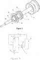
- Figure 9 shows how a centralising pin 28, and the centralising pin 12, may be used to provide a switched signal to or from the computer control means 48.
- each pin may be used as separate switches to conduct electricity and provide signals back to the computer control means 48.
- the switched feedback signals from the centralising pins may be used to accurately control the signals to the stepper motors so that a measured amount of pressure is placed upon the rotating centre shaft by the centralising pins.
- the rotating centre shaft 7 can be vertically adjusted by moving the magnet arrangements to re-establish the connection.
- Figure 8 shows how the horizontal array of the permanent magnets of the present invention may be misaligned with the centre line 69, of the none-rotating magnet 38, may be below the centre line 68, of the rotating magnet 36.
- Figure 7 shows how the horizontal array of the permanent magnets of the present invention may be correctly aligned with the centre line 69, of the none-rotating magnet 38, may be at the same vertical height as the centre line 68, of the rotating magnet 36.
- the computer control means 48 maintains the position of all of the adjustment means within the present invention so that the vertical positioning of the rotating centre shaft 7, is such that the position of the horizontal array of permanent magnets is aligned as shown in figure 7 .
- Figure 11 shows how the rotating permanent magnets 31, and the none-rotating permanent magnets 33, of the bottom vertical array of magnets may be positioned so that like poles of the magnets are facing each other, therefor when the adjustment means 34, is adjusted to lift the none-rotating magnets 33, vertically upwards the opposing magnetic field pushes the rotating magnet 31 upwards and the supporting means 32 then lifts the rotating centre shaft 7, into a position calculated by the computer control means and corresponding to the amount of fluid within the flywheel. Both the top and bottom vertical array of magnets operate in the same way in order to lift the rotating centre shaft 7.
- Figure 9 shows how a centralising pin may be used to provide a switched signal to or from the computer control means.
- Figure 13 shows an adjustment means, or adjustable magnetic support means, 101, which is securely attached to one or more magnet securing means 18.
- the magnet securing means 18, is used to securely hold the magnet 17 so that it will move in a vertical axis when the adjustable magnetic support means 101, is moved vertically.
- a magnet securing means 16, is used to securely hold a magnet 15.
- the magnets 15, and 17, are aligned so that the opposite poles of the magnet are facing each other and, thus, the magnets are attracted to one another and the pull towards each other.
- each pin may be used as a switch to conduct electricity and provide a signal back to the computer control means 48.
- the switched feedback signal from the centralising pin may be used to accurately control the signals to the stepper motor so that a measured amount of pressure is placed upon the rotating centre shaft by the centralising pins.
- all of the adjustment means within the present invention may be provided by a series of pistons and cylinders and a controlled hydraulic or pneumatic pressure to move all adjustment means.
- the computer control means may be used to adjust pressures to pistons and cylinders in order to accurately adjust the position of all adjustment means within the present invention.
- a plurality of sensors within the present invention may provide the computer control means with signals to aid the computer control means to determine how much pressure is needed in each cylinder to accurately position each adjustment means.
- the flywheel may comprise a peripheral reservoir created by the cavities 49.
- the top and/or bottom pins may be moved in combination with the magnetic support and stabilisation means so that the pin(s) may act to stabilise the rotatable centre shaft.
- the shaft is raised using the vertical support arrangement to reduce the friction.
- the pin(s) may be raised to keep in contact with the shaft with the whole arrangement moving in combination.
- the contact should be minimal and the pin(s) should be just touching the shaft in order to keep the shaft in a stable, substantially vertical, alignment.
- the pins comprise an electrical contact
- the overall contact between the pins and the shaft can be monitored by the computer to reduce the contact, and thus the frictional interference, preferably making this as low as possible.
- the magnet supporting means may be brackets to which magnets are connected.
Landscapes
- Engineering & Computer Science (AREA)
- General Engineering & Computer Science (AREA)
- Mechanical Engineering (AREA)
- Physics & Mathematics (AREA)
- Acoustics & Sound (AREA)
- Aviation & Aerospace Engineering (AREA)
- Power Engineering (AREA)
- Magnetic Bearings And Hydrostatic Bearings (AREA)
- Connection Of Motors, Electrical Generators, Mechanical Devices, And The Like (AREA)
Claims (10)
- Agencement de volant d'inertie comprenant un volant d'inertie (6) et des moyens de support (18), un arbre rotatif (7) du volant d'inertie (6) étant agencé pour être supporté à l'intérieur des moyens de support (18) au moyen d'une configuration d'évidement (51) et de pointe (12) agencée au moins au niveau d'une extrémité de l'arbre rotatif (7), ladite extrémité de l'arbre rotatif (7) étant dotée de deux aimants (20 et 15), lesdits moyens de support (18) comprenant :un premier agencement d'aimants (22) permettant la stabilisation horizontale de l'arbre (7) ; et un second agencement d'aimants (17) permettant la stabilisation verticale de l'arbre (7) ; ledit premier des deux aimants (20) de l'arbre interagissant avec le premier agencement (22) et ledit second des deux aimants (15) de l'arbre interagissant avec le second agencement (17), etcaractérisé en ce que la position verticale des moyens de support (18) peut être réglée pour modifier la position verticale de l'arbre (7) du volant d'inertie.
- Agencement de volant d'inertie selon la revendication 1, caractérisé en ce que le premier agencement (22) comprend un aimant toroïdal et ledit premier aimant (20) d'arbre est agencé coaxialement à l'aimant (22) du premier agencement et sensiblement à l'intérieur de celui-ci.
- Agencement de volant d'inertie selon la revendication 2, caractérisé en ce que le premier aimant (20) d'arbre est toroïdal et possède un diamètre inférieur à celui de l'aimant toroïdal du premier agencement (22).
- Agencement de volant d'inertie selon l'une quelconque des revendications précédentes, caractérisé en ce que le second agencement (17) comprend un aimant toroïdal et le second aimant (15) d'arbre est agencé coaxialement à l'aimant du second agencement (17) et adjacent à celui-ci.
- Agencement de volant d'inertie selon la revendication 4, caractérisée en ce que le second aimant (15) d'arbre est toroïdal et possède un diamètre sensiblement égal à celui de l'aimant toroïdal du second agencement (17) et est positionné au-dessus de l'aimant du second agencement.
- Agencement de volant d'inertie selon l'une quelconque des revendications précédentes, caractérisé en ce que les deux extrémités de l'arbre rotatif (7) comprennent deux aimants et des moyens de support associés respectifs.
- Agencement de volant d'inertie selon l'une quelconque des revendications précédentes, caractérisé en ce que la pointe (12) est disposée de manière à être reçue dans l'évidement (51) et que la pointe (12) est électroconductrice.
- Agencement de volant d'inertie selon l'une quelconque des revendications précédentes, caractérisé en ce que l'arbre (7) comprend en outre des paliers magnétiques et un bâti doté de paliers magnétiques respectifs pour léviter l'arbre du bâti.
- Agencement de volant d'inertie selon l'une quelconque des revendications précédentes, caractérisé en ce qu'un ordinateur est prévu pour surveiller la position de l'arbre et pour régler les moyens de support afin de modifier la hauteur verticale de l'arbre.
- Procédé de stabilisation d'un volant d'inertie dans un agencement de volant d'inertie selon la revendication 7, caractérisé en ce que l'arbre (7) du volant d'inertie est doté d'un contact électrique dans sa partie respective de la configuration d'évidement et de pointe, ledit procédé comprenant les étapes de surveillance du flux électrique à travers la pointe (12) de la configuration d'évidement et de pointe et le réglage de la position verticale de l'arbre (7) à l'aide d'un moteur pas à pas (54) jusqu'à ce que le flux cesse et le réglage de la position verticale de l'arbre (7) jusqu'à ce que le contact électrique soit rétabli.
Priority Applications (1)
| Application Number | Priority Date | Filing Date | Title |
|---|---|---|---|
| PL15730213T PL3146224T3 (pl) | 2014-05-23 | 2015-05-22 | Układ koła zamachowego |
Applications Claiming Priority (2)
| Application Number | Priority Date | Filing Date | Title |
|---|---|---|---|
| GB1409264.7A GB2526374B (en) | 2014-05-23 | 2014-05-23 | A magnetic support for a flywheel containing fluid |
| PCT/GB2015/000150 WO2015177496A1 (fr) | 2014-05-23 | 2015-05-22 | Agencement de volant d'inertie |
Publications (2)
| Publication Number | Publication Date |
|---|---|
| EP3146224A1 EP3146224A1 (fr) | 2017-03-29 |
| EP3146224B1 true EP3146224B1 (fr) | 2019-04-10 |
Family
ID=51177403
Family Applications (1)
| Application Number | Title | Priority Date | Filing Date |
|---|---|---|---|
| EP15730213.4A Active EP3146224B1 (fr) | 2014-05-23 | 2015-05-22 | Agencement de volant d'inertie |
Country Status (12)
| Country | Link |
|---|---|
| US (1) | US10260595B2 (fr) |
| EP (1) | EP3146224B1 (fr) |
| JP (1) | JP6803831B2 (fr) |
| CN (1) | CN106662148B (fr) |
| CA (1) | CA2971524C (fr) |
| DK (1) | DK3146224T3 (fr) |
| ES (1) | ES2734199T3 (fr) |
| GB (1) | GB2526374B (fr) |
| PL (1) | PL3146224T3 (fr) |
| PT (1) | PT3146224T (fr) |
| TR (1) | TR201910078T4 (fr) |
| WO (1) | WO2015177496A1 (fr) |
Families Citing this family (7)
| Publication number | Priority date | Publication date | Assignee | Title |
|---|---|---|---|---|
| CN108988574A (zh) * | 2017-06-05 | 2018-12-11 | 翁寿成 | 垂直式磁力传动发电装置 |
| TWI676338B (zh) * | 2018-02-06 | 2019-11-01 | 翁壽成 | 節能發電裝置 |
| KR101908259B1 (ko) * | 2018-02-26 | 2018-12-18 | 부산대학교 산학협력단 | 밀폐형 하우징 |
| GB2575699B (en) * | 2018-11-12 | 2020-08-05 | Heptron International Ltd | A flywheel arrangement |
| US11170925B2 (en) * | 2020-03-27 | 2021-11-09 | Fu-Hung Ho | Flywheel device with magnetically floating function |
| CN113890264B (zh) * | 2021-10-20 | 2023-02-03 | 哈尔滨工业大学 | 一种月壤填充式磁悬浮飞轮储能装置 |
| CN114086600B (zh) * | 2021-11-19 | 2023-11-17 | 南阳市佰博工程咨询有限公司 | 一种储能轮及其真空室的建造方法 |
Family Cites Families (19)
| Publication number | Priority date | Publication date | Assignee | Title |
|---|---|---|---|---|
| FR2356044A1 (fr) | 1975-12-02 | 1978-01-20 | Battelle Development Corp | Dispositif pour assurer la sustentation magnetique et le centrage d'un rotor de machine tournante par rapport a son stator, ainsi que machine de stockage d'energie inertielle equipee d'un tel dispositif |
| JPS58217840A (ja) | 1982-06-08 | 1983-12-17 | Mitsubishi Electric Corp | フライホイ−ル式蓄エネルギ装置 |
| JP2509468Y2 (ja) * | 1987-09-14 | 1996-09-04 | セイコー精機株式会社 | 回転体軸受装置 |
| JPH0510328A (ja) * | 1991-07-03 | 1993-01-19 | Nippon Seiko Kk | 高速遠心分離機 |
| JP3353182B2 (ja) * | 1994-07-22 | 2002-12-03 | 株式会社四国総合研究所 | 超電導体の磁気保持力測定装置および測定方法 |
| GB2293281A (en) * | 1994-08-08 | 1996-03-20 | British Nuclear Fuels Plc | An energy storage and conversion apparatus |
| US6150742A (en) * | 1994-08-08 | 2000-11-21 | British Nuclear Fuels Plc | Energy storage and conversion apparatus |
| US6630761B1 (en) | 2000-08-10 | 2003-10-07 | Christopher W. Gabrys | Combination mechanical and magnetic support for a flywheel power supply |
| US6727616B1 (en) * | 2000-11-08 | 2004-04-27 | Christopher W. Gabrys | Flywheel energy storage system with quill stabilizer |
| US6707187B1 (en) * | 2000-11-10 | 2004-03-16 | Indigo Energy, Inc. | Flywheel system with tilt switch |
| EP1249396A4 (fr) | 2000-11-22 | 2004-12-15 | Mitsubishi Heavy Ind Ltd | Mecanisme de soutien pour appareil de rotation en microgravite |
| US6710489B1 (en) * | 2001-08-30 | 2004-03-23 | Indigo Energy, Inc. | Axially free flywheel system |
| WO2010074752A1 (fr) * | 2008-12-22 | 2010-07-01 | Progressive Flywheel Energy, Inc. | Batterie de stockage d'énergie par volant d'inertie |
| AU2011264367B2 (en) * | 2010-06-08 | 2016-08-18 | Bc New Energy (Tianjin) Co., Ltd. | Flywheel energy system |
| CN102082483B (zh) * | 2011-02-16 | 2012-07-25 | 东南大学 | 一种带有永磁轴承和止推轴承的飞轮储能装置 |
| GB201104931D0 (en) * | 2011-03-24 | 2011-05-04 | Liverpool Renewable Energy Res Ct The | Modular multiple liquid flywheel |
| CN102723804B (zh) * | 2012-06-18 | 2014-04-09 | 江苏大学 | 分体式磁悬浮开关磁阻电机支承与传动的飞轮电池 |
| GB201221186D0 (en) | 2012-11-24 | 2013-01-09 | Heptron Powert Transmission Ltd | A magnetic support for a flywheel containing fluid |
| KR101550962B1 (ko) * | 2013-07-02 | 2015-09-08 | 한양대학교 산학협력단 | 에너지 저장 장치 |
-
2014
- 2014-05-23 GB GB1409264.7A patent/GB2526374B/en active Active
-
2015
- 2015-05-22 CN CN201580039893.3A patent/CN106662148B/zh not_active Expired - Fee Related
- 2015-05-22 JP JP2017513363A patent/JP6803831B2/ja not_active Expired - Fee Related
- 2015-05-22 US US15/313,679 patent/US10260595B2/en active Active
- 2015-05-22 PL PL15730213T patent/PL3146224T3/pl unknown
- 2015-05-22 ES ES15730213T patent/ES2734199T3/es active Active
- 2015-05-22 PT PT15730213T patent/PT3146224T/pt unknown
- 2015-05-22 EP EP15730213.4A patent/EP3146224B1/fr active Active
- 2015-05-22 DK DK15730213.4T patent/DK3146224T3/da active
- 2015-05-22 TR TR2019/10078T patent/TR201910078T4/tr unknown
- 2015-05-22 CA CA2971524A patent/CA2971524C/fr active Active
- 2015-05-22 WO PCT/GB2015/000150 patent/WO2015177496A1/fr not_active Ceased
Non-Patent Citations (1)
| Title |
|---|
| None * |
Also Published As
| Publication number | Publication date |
|---|---|
| DK3146224T3 (da) | 2019-07-22 |
| US10260595B2 (en) | 2019-04-16 |
| TR201910078T4 (tr) | 2019-07-22 |
| US20170146092A1 (en) | 2017-05-25 |
| JP6803831B2 (ja) | 2020-12-23 |
| PL3146224T3 (pl) | 2019-10-31 |
| ES2734199T3 (es) | 2019-12-04 |
| EP3146224A1 (fr) | 2017-03-29 |
| WO2015177496A1 (fr) | 2015-11-26 |
| GB201409264D0 (en) | 2014-07-09 |
| PT3146224T (pt) | 2019-07-16 |
| CN106662148A (zh) | 2017-05-10 |
| CA2971524A1 (fr) | 2015-11-26 |
| CA2971524C (fr) | 2022-07-19 |
| CN106662148B (zh) | 2019-08-06 |
| JP2017517704A (ja) | 2017-06-29 |
| GB2526374A (en) | 2015-11-25 |
| GB2526374B (en) | 2016-10-26 |
Similar Documents
| Publication | Publication Date | Title |
|---|---|---|
| CA2971524C (fr) | Agencement de volant d'inertie | |
| US6570286B1 (en) | Full magnetic bearings with increased load capacity | |
| US10797578B2 (en) | Vertically mounted and magnetically driven power generation apparatus | |
| US8410629B2 (en) | Tapered magnetic thrust bearing within an electric generator with adjusting air gap controls | |
| US10240660B2 (en) | Safe assembly and installation of a flywheel | |
| EP2923109B1 (fr) | Volant d'inertie | |
| US20130015825A1 (en) | Flywheel apparatus | |
| CN215567323U (zh) | 离心机 | |
| WO1997024537A1 (fr) | Paliers de renfort pour prises de contact a des vitesses extremes | |
| JP5916022B2 (ja) | 慣性エネルギー蓄積装置 | |
| CN206865286U (zh) | 飞轮储能转子、系统、车间、工厂和基地及其应用设备 | |
| HK1236240A1 (en) | A flywheel arrangement | |
| HK1236240B (en) | A flywheel arrangement | |
| CA2989308C (fr) | Assemblage et installation d'un volant d'inertie en toute securite | |
| EP2626559A2 (fr) | Appareil rotatif excentrique | |
| JP2021530948A (ja) | 電気機械バッテリ | |
| CN113904493B (zh) | 电磁动力飞轮装置及具有其的设备 | |
| US7080509B2 (en) | System for obtaining rotational energy from ambient forces | |
| CN219452280U (zh) | 一种磁悬浮卸载装置 | |
| JP2001041241A (ja) | 超電導磁気浮上装置、超電導電力貯蔵方法および超電導磁気軸受試験方法 | |
| KR100851646B1 (ko) | 초전도 플라이 휠 | |
| JP3632101B2 (ja) | 電力貯蔵装置 | |
| JP2024054031A (ja) | フライホイール装置 | |
| KR20100054556A (ko) | 초전도 플라이휠 에너지 저장장치 | |
| CN114810824A (zh) | 一种三自由度永磁悬浮轴承及其调控方法 |
Legal Events
| Date | Code | Title | Description |
|---|---|---|---|
| STAA | Information on the status of an ep patent application or granted ep patent |
Free format text: STATUS: THE INTERNATIONAL PUBLICATION HAS BEEN MADE |
|
| PUAI | Public reference made under article 153(3) epc to a published international application that has entered the european phase |
Free format text: ORIGINAL CODE: 0009012 |
|
| STAA | Information on the status of an ep patent application or granted ep patent |
Free format text: STATUS: REQUEST FOR EXAMINATION WAS MADE |
|
| 17P | Request for examination filed |
Effective date: 20161216 |
|
| AK | Designated contracting states |
Kind code of ref document: A1 Designated state(s): AL AT BE BG CH CY CZ DE DK EE ES FI FR GB GR HR HU IE IS IT LI LT LU LV MC MK MT NL NO PL PT RO RS SE SI SK SM TR |
|
| AX | Request for extension of the european patent |
Extension state: BA ME |
|
| DAV | Request for validation of the european patent (deleted) | ||
| DAX | Request for extension of the european patent (deleted) | ||
| STAA | Information on the status of an ep patent application or granted ep patent |
Free format text: STATUS: EXAMINATION IS IN PROGRESS |
|
| 17Q | First examination report despatched |
Effective date: 20180104 |
|
| REG | Reference to a national code |
Ref country code: HK Ref legal event code: DE Ref document number: 1236240 Country of ref document: HK |
|
| GRAP | Despatch of communication of intention to grant a patent |
Free format text: ORIGINAL CODE: EPIDOSNIGR1 |
|
| STAA | Information on the status of an ep patent application or granted ep patent |
Free format text: STATUS: GRANT OF PATENT IS INTENDED |
|
| INTG | Intention to grant announced |
Effective date: 20180831 |
|
| GRAJ | Information related to disapproval of communication of intention to grant by the applicant or resumption of examination proceedings by the epo deleted |
Free format text: ORIGINAL CODE: EPIDOSDIGR1 |
|
| STAA | Information on the status of an ep patent application or granted ep patent |
Free format text: STATUS: EXAMINATION IS IN PROGRESS |
|
| GRAP | Despatch of communication of intention to grant a patent |
Free format text: ORIGINAL CODE: EPIDOSNIGR1 |
|
| STAA | Information on the status of an ep patent application or granted ep patent |
Free format text: STATUS: GRANT OF PATENT IS INTENDED |
|
| INTC | Intention to grant announced (deleted) | ||
| INTG | Intention to grant announced |
Effective date: 20181023 |
|
| RAP1 | Party data changed (applicant data changed or rights of an application transferred) |
Owner name: HEPTRON INTERNATIONAL LIMITED |
|
| GRAS | Grant fee paid |
Free format text: ORIGINAL CODE: EPIDOSNIGR3 |
|
| GRAA | (expected) grant |
Free format text: ORIGINAL CODE: 0009210 |
|
| STAA | Information on the status of an ep patent application or granted ep patent |
Free format text: STATUS: THE PATENT HAS BEEN GRANTED |
|
| AK | Designated contracting states |
Kind code of ref document: B1 Designated state(s): AL AT BE BG CH CY CZ DE DK EE ES FI FR GB GR HR HU IE IS IT LI LT LU LV MC MK MT NL NO PL PT RO RS SE SI SK SM TR |
|
| REG | Reference to a national code |
Ref country code: GB Ref legal event code: FG4D |
|
| REG | Reference to a national code |
Ref country code: CH Ref legal event code: EP Ref country code: AT Ref legal event code: REF Ref document number: 1119076 Country of ref document: AT Kind code of ref document: T Effective date: 20190415 |
|
| REG | Reference to a national code |
Ref country code: IE Ref legal event code: FG4D |
|
| REG | Reference to a national code |
Ref country code: DE Ref legal event code: R096 Ref document number: 602015028017 Country of ref document: DE |
|
| REG | Reference to a national code |
Ref country code: CH Ref legal event code: NV Representative=s name: TR-IP CONSULTING LLC, CH |
|
| REG | Reference to a national code |
Ref country code: PT Ref legal event code: SC4A Ref document number: 3146224 Country of ref document: PT Date of ref document: 20190716 Kind code of ref document: T Free format text: AVAILABILITY OF NATIONAL TRANSLATION Effective date: 20190709 |
|
| REG | Reference to a national code |
Ref country code: NO Ref legal event code: T2 Effective date: 20190410 Ref country code: DK Ref legal event code: T3 Effective date: 20190718 |
|
| REG | Reference to a national code |
Ref country code: NL Ref legal event code: FP |
|
| REG | Reference to a national code |
Ref country code: SE Ref legal event code: TRGR |
|
| REG | Reference to a national code |
Ref country code: LT Ref legal event code: MG4D |
|
| REG | Reference to a national code |
Ref country code: GR Ref legal event code: EP Ref document number: 20190402074 Country of ref document: GR Effective date: 20191016 |
|
| PG25 | Lapsed in a contracting state [announced via postgrant information from national office to epo] |
Ref country code: LT Free format text: LAPSE BECAUSE OF FAILURE TO SUBMIT A TRANSLATION OF THE DESCRIPTION OR TO PAY THE FEE WITHIN THE PRESCRIBED TIME-LIMIT Effective date: 20190410 Ref country code: AL Free format text: LAPSE BECAUSE OF FAILURE TO SUBMIT A TRANSLATION OF THE DESCRIPTION OR TO PAY THE FEE WITHIN THE PRESCRIBED TIME-LIMIT Effective date: 20190410 Ref country code: HR Free format text: LAPSE BECAUSE OF FAILURE TO SUBMIT A TRANSLATION OF THE DESCRIPTION OR TO PAY THE FEE WITHIN THE PRESCRIBED TIME-LIMIT Effective date: 20190410 |
|
| PG25 | Lapsed in a contracting state [announced via postgrant information from national office to epo] |
Ref country code: BG Free format text: LAPSE BECAUSE OF FAILURE TO SUBMIT A TRANSLATION OF THE DESCRIPTION OR TO PAY THE FEE WITHIN THE PRESCRIBED TIME-LIMIT Effective date: 20190710 Ref country code: RS Free format text: LAPSE BECAUSE OF FAILURE TO SUBMIT A TRANSLATION OF THE DESCRIPTION OR TO PAY THE FEE WITHIN THE PRESCRIBED TIME-LIMIT Effective date: 20190410 Ref country code: LV Free format text: LAPSE BECAUSE OF FAILURE TO SUBMIT A TRANSLATION OF THE DESCRIPTION OR TO PAY THE FEE WITHIN THE PRESCRIBED TIME-LIMIT Effective date: 20190410 |
|
| REG | Reference to a national code |
Ref country code: ES Ref legal event code: FG2A Ref document number: 2734199 Country of ref document: ES Kind code of ref document: T3 Effective date: 20191204 |
|
| REG | Reference to a national code |
Ref country code: DE Ref legal event code: R097 Ref document number: 602015028017 Country of ref document: DE |
|
| PG25 | Lapsed in a contracting state [announced via postgrant information from national office to epo] |
Ref country code: EE Free format text: LAPSE BECAUSE OF FAILURE TO SUBMIT A TRANSLATION OF THE DESCRIPTION OR TO PAY THE FEE WITHIN THE PRESCRIBED TIME-LIMIT Effective date: 20190410 Ref country code: SK Free format text: LAPSE BECAUSE OF FAILURE TO SUBMIT A TRANSLATION OF THE DESCRIPTION OR TO PAY THE FEE WITHIN THE PRESCRIBED TIME-LIMIT Effective date: 20190410 Ref country code: MC Free format text: LAPSE BECAUSE OF FAILURE TO SUBMIT A TRANSLATION OF THE DESCRIPTION OR TO PAY THE FEE WITHIN THE PRESCRIBED TIME-LIMIT Effective date: 20190410 Ref country code: RO Free format text: LAPSE BECAUSE OF FAILURE TO SUBMIT A TRANSLATION OF THE DESCRIPTION OR TO PAY THE FEE WITHIN THE PRESCRIBED TIME-LIMIT Effective date: 20190410 |
|
| PLBE | No opposition filed within time limit |
Free format text: ORIGINAL CODE: 0009261 |
|
| REG | Reference to a national code |
Ref country code: CH Ref legal event code: PCAR Free format text: NEW ADDRESS: ROUTE DU COUTSET 18, 1485 NUVILLY (CH) |
|
| STAA | Information on the status of an ep patent application or granted ep patent |
Free format text: STATUS: NO OPPOSITION FILED WITHIN TIME LIMIT |
|
| PG25 | Lapsed in a contracting state [announced via postgrant information from national office to epo] |
Ref country code: SM Free format text: LAPSE BECAUSE OF FAILURE TO SUBMIT A TRANSLATION OF THE DESCRIPTION OR TO PAY THE FEE WITHIN THE PRESCRIBED TIME-LIMIT Effective date: 20190410 |
|
| 26N | No opposition filed |
Effective date: 20200113 |
|
| PG25 | Lapsed in a contracting state [announced via postgrant information from national office to epo] |
Ref country code: SI Free format text: LAPSE BECAUSE OF FAILURE TO SUBMIT A TRANSLATION OF THE DESCRIPTION OR TO PAY THE FEE WITHIN THE PRESCRIBED TIME-LIMIT Effective date: 20190410 |
|
| REG | Reference to a national code |
Ref country code: AT Ref legal event code: UEP Ref document number: 1119076 Country of ref document: AT Kind code of ref document: T Effective date: 20190410 |
|
| PG25 | Lapsed in a contracting state [announced via postgrant information from national office to epo] |
Ref country code: CY Free format text: LAPSE BECAUSE OF FAILURE TO SUBMIT A TRANSLATION OF THE DESCRIPTION OR TO PAY THE FEE WITHIN THE PRESCRIBED TIME-LIMIT Effective date: 20190410 |
|
| PG25 | Lapsed in a contracting state [announced via postgrant information from national office to epo] |
Ref country code: HU Free format text: LAPSE BECAUSE OF FAILURE TO SUBMIT A TRANSLATION OF THE DESCRIPTION OR TO PAY THE FEE WITHIN THE PRESCRIBED TIME-LIMIT; INVALID AB INITIO Effective date: 20150522 |
|
| PG25 | Lapsed in a contracting state [announced via postgrant information from national office to epo] |
Ref country code: MK Free format text: LAPSE BECAUSE OF FAILURE TO SUBMIT A TRANSLATION OF THE DESCRIPTION OR TO PAY THE FEE WITHIN THE PRESCRIBED TIME-LIMIT Effective date: 20190410 |
|
| PGFP | Annual fee paid to national office [announced via postgrant information from national office to epo] |
Ref country code: PT Payment date: 20221121 Year of fee payment: 8 Ref country code: NO Payment date: 20221130 Year of fee payment: 8 Ref country code: AT Payment date: 20221130 Year of fee payment: 8 Ref country code: CZ Payment date: 20221122 Year of fee payment: 8 Ref country code: TR Payment date: 20221121 Year of fee payment: 8 Ref country code: LU Payment date: 20221128 Year of fee payment: 8 Ref country code: IT Payment date: 20221130 Year of fee payment: 8 Ref country code: FI Payment date: 20221130 Year of fee payment: 8 Ref country code: DK Payment date: 20221130 Year of fee payment: 8 |
|
| PGFP | Annual fee paid to national office [announced via postgrant information from national office to epo] |
Ref country code: PL Payment date: 20221121 Year of fee payment: 8 Ref country code: IS Payment date: 20221130 Year of fee payment: 8 Ref country code: GR Payment date: 20221129 Year of fee payment: 8 Ref country code: CH Payment date: 20221129 Year of fee payment: 8 Ref country code: BE Payment date: 20221128 Year of fee payment: 8 |
|
| PGFP | Annual fee paid to national office [announced via postgrant information from national office to epo] |
Ref country code: MT Payment date: 20221130 Year of fee payment: 8 |
|
| P01 | Opt-out of the competence of the unified patent court (upc) registered |
Effective date: 20230525 |
|
| REG | Reference to a national code |
Ref country code: NO Ref legal event code: MMEP |
|
| PGFP | Annual fee paid to national office [announced via postgrant information from national office to epo] |
Ref country code: NL Payment date: 20231130 Year of fee payment: 9 |
|
| REG | Reference to a national code |
Ref country code: CH Ref legal event code: PL |
|
| REG | Reference to a national code |
Ref country code: DK Ref legal event code: EBP Effective date: 20230531 |
|
| REG | Reference to a national code |
Ref country code: AT Ref legal event code: MM01 Ref document number: 1119076 Country of ref document: AT Kind code of ref document: T Effective date: 20230522 |
|
| PG25 | Lapsed in a contracting state [announced via postgrant information from national office to epo] |
Ref country code: GR Free format text: LAPSE BECAUSE OF NON-PAYMENT OF DUE FEES Effective date: 20231208 |
|
| PGFP | Annual fee paid to national office [announced via postgrant information from national office to epo] |
Ref country code: ES Payment date: 20231130 Year of fee payment: 9 |
|
| REG | Reference to a national code |
Ref country code: BE Ref legal event code: MM Effective date: 20230531 |
|
| PG25 | Lapsed in a contracting state [announced via postgrant information from national office to epo] |
Ref country code: PT Free format text: LAPSE BECAUSE OF NON-PAYMENT OF DUE FEES Effective date: 20231122 Ref country code: NO Free format text: LAPSE BECAUSE OF NON-PAYMENT OF DUE FEES Effective date: 20230531 Ref country code: LU Free format text: LAPSE BECAUSE OF NON-PAYMENT OF DUE FEES Effective date: 20230522 Ref country code: LI Free format text: LAPSE BECAUSE OF NON-PAYMENT OF DUE FEES Effective date: 20230531 Ref country code: GR Free format text: LAPSE BECAUSE OF NON-PAYMENT OF DUE FEES Effective date: 20231208 Ref country code: FI Free format text: LAPSE BECAUSE OF NON-PAYMENT OF DUE FEES Effective date: 20230522 Ref country code: CZ Free format text: LAPSE BECAUSE OF NON-PAYMENT OF DUE FEES Effective date: 20230522 Ref country code: CH Free format text: LAPSE BECAUSE OF NON-PAYMENT OF DUE FEES Effective date: 20230531 Ref country code: AT Free format text: LAPSE BECAUSE OF NON-PAYMENT OF DUE FEES Effective date: 20230522 |
|
| PGFP | Annual fee paid to national office [announced via postgrant information from national office to epo] |
Ref country code: SE Payment date: 20231130 Year of fee payment: 9 Ref country code: IE Payment date: 20231130 Year of fee payment: 9 Ref country code: FR Payment date: 20231129 Year of fee payment: 9 Ref country code: DE Payment date: 20231130 Year of fee payment: 9 |
|
| PG25 | Lapsed in a contracting state [announced via postgrant information from national office to epo] |
Ref country code: IT Free format text: LAPSE BECAUSE OF NON-PAYMENT OF DUE FEES Effective date: 20230522 Ref country code: DK Free format text: LAPSE BECAUSE OF NON-PAYMENT OF DUE FEES Effective date: 20230531 |
|
| PG25 | Lapsed in a contracting state [announced via postgrant information from national office to epo] |
Ref country code: BE Free format text: LAPSE BECAUSE OF NON-PAYMENT OF DUE FEES Effective date: 20230531 |
|
| REG | Reference to a national code |
Ref country code: DE Ref legal event code: R119 Ref document number: 602015028017 Country of ref document: DE |
|
| REG | Reference to a national code |
Ref country code: SE Ref legal event code: EUG |
|
| REG | Reference to a national code |
Ref country code: NL Ref legal event code: MM Effective date: 20240601 |
|
| PG25 | Lapsed in a contracting state [announced via postgrant information from national office to epo] |
Ref country code: PL Free format text: LAPSE BECAUSE OF NON-PAYMENT OF DUE FEES Effective date: 20230522 |
|
| PG25 | Lapsed in a contracting state [announced via postgrant information from national office to epo] |
Ref country code: PL Free format text: LAPSE BECAUSE OF NON-PAYMENT OF DUE FEES Effective date: 20230522 |
|
| PG25 | Lapsed in a contracting state [announced via postgrant information from national office to epo] |
Ref country code: NL Free format text: LAPSE BECAUSE OF NON-PAYMENT OF DUE FEES Effective date: 20240601 |
|
| PG25 | Lapsed in a contracting state [announced via postgrant information from national office to epo] |
Ref country code: DE Free format text: LAPSE BECAUSE OF NON-PAYMENT OF DUE FEES Effective date: 20241203 |
|
| PG25 | Lapsed in a contracting state [announced via postgrant information from national office to epo] |
Ref country code: IE Free format text: LAPSE BECAUSE OF NON-PAYMENT OF DUE FEES Effective date: 20240522 |
|
| PG25 | Lapsed in a contracting state [announced via postgrant information from national office to epo] |
Ref country code: FR Free format text: LAPSE BECAUSE OF NON-PAYMENT OF DUE FEES Effective date: 20240531 |
|
| REG | Reference to a national code |
Ref country code: ES Ref legal event code: FD2A Effective date: 20250703 |
|
| PG25 | Lapsed in a contracting state [announced via postgrant information from national office to epo] |
Ref country code: ES Free format text: LAPSE BECAUSE OF NON-PAYMENT OF DUE FEES Effective date: 20240523 |
|
| PGFP | Annual fee paid to national office [announced via postgrant information from national office to epo] |
Ref country code: GB Payment date: 20250529 Year of fee payment: 11 |
|
| PG25 | Lapsed in a contracting state [announced via postgrant information from national office to epo] |
Ref country code: SE Free format text: LAPSE BECAUSE OF NON-PAYMENT OF DUE FEES Effective date: 20240523 |
|
| PG25 | Lapsed in a contracting state [announced via postgrant information from national office to epo] |
Ref country code: IS Free format text: LAPSE BECAUSE OF NON-PAYMENT OF DUE FEES Effective date: 20231204 |