EP3146228B1 - Support de frein - Google Patents
Support de frein Download PDFInfo
- Publication number
- EP3146228B1 EP3146228B1 EP15723909.6A EP15723909A EP3146228B1 EP 3146228 B1 EP3146228 B1 EP 3146228B1 EP 15723909 A EP15723909 A EP 15723909A EP 3146228 B1 EP3146228 B1 EP 3146228B1
- Authority
- EP
- European Patent Office
- Prior art keywords
- engagement
- axis
- support unit
- flange portion
- guiding
- Prior art date
- Legal status (The legal status is an assumption and is not a legal conclusion. Google has not performed a legal analysis and makes no representation as to the accuracy of the status listed.)
- Active
Links
Images
Classifications
-
- B—PERFORMING OPERATIONS; TRANSPORTING
- B60—VEHICLES IN GENERAL
- B60T—VEHICLE BRAKE CONTROL SYSTEMS OR PARTS THEREOF; BRAKE CONTROL SYSTEMS OR PARTS THEREOF, IN GENERAL; ARRANGEMENT OF BRAKING ELEMENTS ON VEHICLES IN GENERAL; PORTABLE DEVICES FOR PREVENTING UNWANTED MOVEMENT OF VEHICLES; VEHICLE MODIFICATIONS TO FACILITATE COOLING OF BRAKES
- B60T17/00—Component parts, details, or accessories of power brake systems not covered by groups B60T8/00, B60T13/00 or B60T15/00, or presenting other characteristic features
- B60T17/08—Brake cylinders other than ultimate actuators
- B60T17/088—Mounting arrangements
-
- F—MECHANICAL ENGINEERING; LIGHTING; HEATING; WEAPONS; BLASTING
- F16—ENGINEERING ELEMENTS AND UNITS; GENERAL MEASURES FOR PRODUCING AND MAINTAINING EFFECTIVE FUNCTIONING OF MACHINES OR INSTALLATIONS; THERMAL INSULATION IN GENERAL
- F16D—COUPLINGS FOR TRANSMITTING ROTATION; CLUTCHES; BRAKES
- F16D65/00—Parts or details
- F16D65/02—Braking members; Mounting thereof
-
- F—MECHANICAL ENGINEERING; LIGHTING; HEATING; WEAPONS; BLASTING
- F16—ENGINEERING ELEMENTS AND UNITS; GENERAL MEASURES FOR PRODUCING AND MAINTAINING EFFECTIVE FUNCTIONING OF MACHINES OR INSTALLATIONS; THERMAL INSULATION IN GENERAL
- F16D—COUPLINGS FOR TRANSMITTING ROTATION; CLUTCHES; BRAKES
- F16D51/00—Brakes with outwardly-movable braking members co-operating with the inner surface of a drum or the like
-
- B—PERFORMING OPERATIONS; TRANSPORTING
- B60—VEHICLES IN GENERAL
- B60T—VEHICLE BRAKE CONTROL SYSTEMS OR PARTS THEREOF; BRAKE CONTROL SYSTEMS OR PARTS THEREOF, IN GENERAL; ARRANGEMENT OF BRAKING ELEMENTS ON VEHICLES IN GENERAL; PORTABLE DEVICES FOR PREVENTING UNWANTED MOVEMENT OF VEHICLES; VEHICLE MODIFICATIONS TO FACILITATE COOLING OF BRAKES
- B60T1/00—Arrangements of braking elements, i.e. of those parts where braking effect occurs specially for vehicles
-
- B—PERFORMING OPERATIONS; TRANSPORTING
- B60—VEHICLES IN GENERAL
- B60T—VEHICLE BRAKE CONTROL SYSTEMS OR PARTS THEREOF; BRAKE CONTROL SYSTEMS OR PARTS THEREOF, IN GENERAL; ARRANGEMENT OF BRAKING ELEMENTS ON VEHICLES IN GENERAL; PORTABLE DEVICES FOR PREVENTING UNWANTED MOVEMENT OF VEHICLES; VEHICLE MODIFICATIONS TO FACILITATE COOLING OF BRAKES
- B60T17/00—Component parts, details, or accessories of power brake systems not covered by groups B60T8/00, B60T13/00 or B60T15/00, or presenting other characteristic features
-
- F—MECHANICAL ENGINEERING; LIGHTING; HEATING; WEAPONS; BLASTING
- F16—ENGINEERING ELEMENTS AND UNITS; GENERAL MEASURES FOR PRODUCING AND MAINTAINING EFFECTIVE FUNCTIONING OF MACHINES OR INSTALLATIONS; THERMAL INSULATION IN GENERAL
- F16D—COUPLINGS FOR TRANSMITTING ROTATION; CLUTCHES; BRAKES
- F16D65/00—Parts or details
- F16D65/005—Components of axially engaging brakes not otherwise provided for
- F16D65/0056—Brake supports
-
- F—MECHANICAL ENGINEERING; LIGHTING; HEATING; WEAPONS; BLASTING
- F16—ENGINEERING ELEMENTS AND UNITS; GENERAL MEASURES FOR PRODUCING AND MAINTAINING EFFECTIVE FUNCTIONING OF MACHINES OR INSTALLATIONS; THERMAL INSULATION IN GENERAL
- F16D—COUPLINGS FOR TRANSMITTING ROTATION; CLUTCHES; BRAKES
- F16D51/00—Brakes with outwardly-movable braking members co-operating with the inner surface of a drum or the like
- F16D2051/001—Parts or details of drum brakes
- F16D2051/003—Brake supports
Definitions
- the present invention relates to a carrier unit for use in brake systems of motor vehicles, preferably of commercial vehicles.
- Carrier units are known from the prior art in that usually cast brake carrier are provided on which the various components of the vehicle brake can be fixed and connected via the brake carrier with, for example, the axis.
- the known from the prior art brake carrier in this case generally have the disadvantage that they are heavy-built and require a high installation cost due to a variety of components to be mounted.
- these additional adapter elements increase the space requirement and, on the other hand, also create a multiplicity of vulnerable connection points through which, for example, dirt and liquids can reach the interior region of the expanding wedge unit. There is therefore a significant need for improvement with regard to the compactness, the susceptibility to errors and the assembly of a brake system.
- the WO 2013/087737 A1 shows a brake carrier of a drum brake with a carrier unit, which has a first connection portion, on which a brake cylinder can be fixed and has a second connection portion, on which a converter unit can be fixed.
- the US 5,613,577 A shows a disc brake of a vehicle which is hydraulically actuated.
- Object of the present invention is to provide a carrier unit, which simplifies both the assembly of the brake system and saves weight and space and reduces the susceptibility of the brake system to failure.
- the carrier unit comprises a first flange portion, a second flange portion and a guide portion, wherein the first flange portion has a first engagement geometry for fixing the carrier unit to a chassis, wherein the second flange portion has a second engagement geometry for fixing a brake cylinder, wherein the guide portion adjacent to the second Flange portion is arranged and has a guide geometry for guiding a guide member along a guide axis, wherein a Sp Drkeilica adjacent to the guide portion is provided and wherein the Sp lanternkeilhow comprises a housing which is integrally formed with the guide portion.
- an expansion wedge unit is formed integrally with the support unit, wherein in particular the housing of the expansion wedge unit is formed integrally with the corresponding adjacent portion of the support unit. Adjacent to the housing of the carrier unit while the guide portion of the carrier unit is provided.
- the guide section is an at least partially hollow-body-shaped section of the carrier unit, in which a guide element is arranged to be displaceable along a guide axis.
- the guide element particularly preferably serves for the transmission of force of a braking force which leads from a brake cylinder flanged to the second flange section to a corresponding expanding wedge mechanism which is arranged in the expanding wedge unit.
- the guide section also has the function of both the geometry of the expanding wedge unit and the guide element and to shield the brake cylinder against the ingress of dirt, debris and liquids.
- the first flange portion has a first engagement geometry for fixing the carrier unit to a running gear, wherein the first engagement geometry is preferably a standardized engagement geometry, which is engageable by default on trolleys of various commercial vehicles or commercial vehicle types.
- the second engagement geometry of the second flange portion is also a standardized interface for fixing a brake cylinder, which is characterized in particular by preferably two engagement geometries, which are provided at a certain, standardized distance from each other.
- the carrier unit can therefore be integrated into existing brake systems, wherein the previously used brake cylinder can be further applied.
- the second flange portion is formed integrally with the guide portion.
- the second flange portion is preferably formed as a one-piece casting together with the guide portion, which advantageously a subsequent assembly of the second flange on the guide portion can be avoided while wall or cross-sectional geometries can be used, which is a particularly good power transmission at the same time Allow wall thickness. Due to the one-piece design of the second flange portion and the guide portion while the weight of the support unit can be reduced and the assembly costs for attaching a brake cylinder to the support unit can be significantly reduced because a fitter must handle only one component.
- the carrier unit has a holding section, which adjoins the first flange section and the guide section and extends substantially along a holding axis, wherein the first flange section, the holding section and the guide portion are formed integrally with each other.
- the holding section preferably serves to position the guide section and thus also the first flange section preferably integrally connected to the guide section and the expanding wedge unit preferably integrally connected to the guide section relative to the chassis.
- the holding portion preferably has an extension along a holding axis, wherein the extension of the holding portion along the holding axis, or parallel to the holding axis is preferably its largest extension.
- force-optimized outer geometries of the holding section are provided, that is to say preferably rounded outer geometries on which advantageously only low notch effect occurs under bending stress of the first flange section and of the holding section.
- the holding axis is transverse, preferably perpendicular to the guide axis.
- an accurate positioning of the power transmission direction from the brake cylinder is defined for Sp Drkeiltician.
- the vertical alignment of the holding portion with its holding axis and the guide portion with the guide axis to each other particularly preferably provides for a uniform force transmission under bending stress, which are transmitted by the relatively heavy brake cylinder on the carrier unit or which are transmitted by vibrations, for example, the brake shoes on the Sp Drssenkeiltician.
- the first engagement geometry extends substantially along an engagement axis, wherein the support axis is pivoted at an angle to the engagement axis and wherein the angle is smaller than 90 °. It is further preferred that the engagement axis, along which the engagement geometry extends or along which the engagement geometry can be advantageously brought into engagement with the chassis of a commercial vehicle, substantially parallel is arranged to an axial direction of the chassis, for example, parallel to the direction of rotation of the vehicle wheels.
- substantially parallel in the context of the present invention means that smaller deviations, for example caused by manufacturing tolerances, are considered parallel in the context of the present invention.
- the carrier unit along the engagement axis which extends parallel to the axial direction with advantage, fixed to the chassis of the commercial vehicle, in particular preferably a good accessibility of the corresponding fastening means along the engagement axis is given.
- the holding axis is pivoted at an angle to the engagement axis, said angle being less than 90 °.
- the angle is measured on the side of the carrier unit on which the expanding wedge unit is located.
- the holding axis By arranging the holding axis obliquely relative to the engagement axis, it is possible to allow the upper part of the carrier unit, that is to say the area consisting of expanding wedge unit, guide section and second flange section, to protrude into the interior of a brake drum, in order to engage the expanding wedge unit in each case To be able to bring brake shoes.
- the brake cylinder is arranged at a sufficient distance from the axis of the commercial vehicle by the oblique arrangement of the holding axis, so that no vibrations due to vibrations and occurring contact between the brake cylinder and adjacent geometries of the chassis occur in vibrations in the suspension system.
- the angle between the engagement axis and the support axis is determined as an angle between the projections of the engagement axis and the support axis on a, preferably through the guide portion extending cutting plane ,
- the angle is in the range of 45 ° to 89 °, preferably in the range of 60 ° to 85 ° and more preferably about 70 ° to 85 °.
- the relatively wide range of 45 ° to 89 ° is preferred for carrier units, which are designed to set especially many different brake cylinder. It has been found that in this range from 45 ° to 89 ° all present on the market brake cylinder can be readily integrated into a brake system with a carrier unit according to the invention, without having to fear damage by striking adjacent chassis geometries.
- the particularly preferred range of 60 ° to 85 ° has proven to be advantageous, since in this way a particularly compact design of the carrier unit is achieved, on the one hand, a sufficient distance of a fixed to the second flange brake cylinder is ensured by the adjacent chassis geometries and on the other hand Extension of the holding section can be chosen relatively small and in this way weight can be saved.
- the particularly preferred range of 70 ° to 85 ° has proven to be advantageous for use with Sp Drokkeilbremsakuen, since an optimal arrangement of the upper portion of the support unit relative to the first engagement geometry or relative to the first flange is reached, on the one hand with weight savings, on the other hand with a as simple as possible to integrate a carrier unit in the braking system of a commercial vehicle.
- the first engagement geometry can be brought indirectly and / or directly into positive engagement with a corresponding section of the chassis.
- An indirect positive engagement is particularly preferably produced by a bolt or a screw connection.
- a direct form-fitting engagement can preferably be made by a projection on the first flange portion or the first engagement geometry, which engages positively in a corresponding recess geometry on the corresponding portion of the chassis to secure, for example, the carrier unit relative to the chassis against rotation about the engagement axis.
- a positive connection of the carrier unit to the chassis is preferred to firstly to ensure disassembly of the carrier unit from the chassis and on the other hand to avoid the occurring at a usual welding joint of the brake carrier to the suspension axle thermal stresses and structural damage.
- a securing element which can be brought along the engagement axis in positive engagement with the first engagement geometry, the securing element being accessible from the side of the carrier unit the spreading wedge unit is located.
- the securing element is preferably a screw or a threaded bolt and is advantageously accessible from the side of the carrier unit on which the expanding wedge unit is located.
- the securing element is preferably accessible from the outside of the chassis, that is, after the wheel and the brake drum of the brake unit have been removed from the chassis, the carrier unit can be removed by loosening the securing element from the outside in a simple manner.
- the securing element may also be designed as a nut, which can be brought into engagement with a first engagement geometry designed, for example, as a threaded rod.
- the securing element can be accessible from the side of the carrier unit on which the second flange section is located.
- the carrier unit can also be disassembled or attached to such without prior disassembly of the wheel, or the brake drum of the brake system, it is preferable to arrange the securing element on the side of the carrier unit on which the second flange portion is located.
- the securing element is thus preferably accessible from the inside of the chassis, wherein the first flange portion and the first engagement geometry are advantageously arranged away from the axle body and other components of the chassis that sufficient space for the use of a torque wrench or a pneumatic screwdriver is available.
- the first engagement geometry is formed as a threaded bore.
- the mounting of the carrier unit on the chassis of a utility vehicle is simplified, since only one screw with an engagement geometry must be brought into engagement to set the carrier unit on the chassis.
- additional provided for nuts or other fixing elements is provided.
- a self-locking ISO thread is provided as the thread type for the first engagement geometry.
- the first engagement geometry is formed as a threaded bolt and preferably designed in one piece with the first flange portion. Also with this alternative embodiment of the first engagement geometry, the required number of required for the assembly of the carrier unit items can be reduced and thus not only weight, but also assembly time can be saved.
- the first flange portion on two engagement geometries which are spaced from each other, wherein the engagement axes of the respective engagement geometries are parallel to each other.
- at least two first engagement geometries are provided.
- the distance of the engagement geometries from each other is preferably smaller than the extension of the holding portion along the support axis.
- two holding sections are provided, which are separated from one another by a free space, wherein the average cross-sectional area of the holding sections in a ratio of 0.2 to 1.3, preferably from 0.3 to 0.9 and particularly preferably from about 0, 5 to 0.8 to the average cross-sectional area of the free space.
- the sum of the cross-sectional areas of the individual holding sections in a cross-section through the carrier unit is preferably selected as the average cross-sectional area of the holding sections, in which the average cross-sectional thickness or width of the holding section extends along the engagement axis of the engagement geometry adjacent to the holding section is present.
- the cross-sectional area of the clearance is preferably determined in the same sectional plane by the carrier unit as the cross-sectional area of the holding portions.
- the ratio of the two cross-sectional areas to each other is an expression of how "solid" the holding sections are executed.
- the carrier unit should have a relatively compact design, take up little space and should have a small distance of the holding sections from each other, the free space compared to the holding sections is relatively small, so that the ratio can increase up to 1.3.
- a range of about 0.5 to 0.8 has been found, and in this ratio range, the best results could be achieved in the context of the present invention.
- the housing of the expanding wedge unit is made of nodular cast iron.
- the formation of nodular cast iron allows on the one hand a precise configuration of the corresponding outer or inner geometries of the expanding wedge unit and on the other a favorable connection by, for example, casting the housing of the expanding wedge unit to the corresponding guide section of the support unit, which are made of a cheaper, relatively less solid material can be used as ductile iron.
- the entire carrier unit is designed together with the housing of the expanding wedge unit as a spheroidal cast iron component.
- the carrier unit has no more than four first engagement geometries, preferably no more than two first engagement geometries.
- the preferred reduction of the number of first engagement geometries reduces the assembly effort.
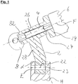
- the Sp Dr.iltician 8 is only partially cut with its housing 82 and otherwise shown very greatly simplified.
- the carrier unit Adjacent to the housing 82 of the expanding wedge unit 8, the carrier unit has a guide section 26, in which a guide element 4 along the guide axis F is arranged displaceably and guided.
- the guide section 26 in particular has a guide geometry 27, which is particularly preferably designed as a cylindrical cavity in the guide section 26 and secures the guide element 4 against displacement transversely to the guide axis F and facilitates sliding of the guide element 4.
- the carrier unit 2 has a second flange section 24 on which a brake cylinder 6 can be fixed or preferably fixed.
- the housing 82 of the expanding wedge unit 8, the guide section 26 and the second flange section 24 are preferably formed integrally with a holding section 28, wherein the holding section extends substantially along a holding axis H.
- the holding section 28 serves to position the upper part of the carrier unit 2 relative to a chassis of the commercial vehicle shown in the lower area of the image.
- the carrier unit preferably has a first flange section 22 which can be fixed indirectly and / or directly to the chassis of the commercial vehicle via a first engagement geometry 23. In the Fig.
- first engagement geometry 23 extends substantially along an engagement axis E, wherein the engagement axis E is advantageously aligned parallel to an axial direction of the commercial vehicle in order to fix the carrier unit 2 along this axial direction on the commercial vehicle.
- the cross section of the first engagement geometry 23 in the course along the engagement axis E is substantially constant, with smaller deviations, such as in the case of a thread, should be considered as substantially constant.
- the holding axis H is preferably pivoted at an angle ⁇ to the engagement axis E, whereby the upper area of the carrier unit 2 and in particular preferably the expanding wedge unit 8 are arranged offset in the figure to the left relative to the first flange portion 22.
- the arrangement of the brake shoes and the surrounding brake drum both not shown
- Due to the inclination of the support axis H relative to the engagement axis E of the arranged on the right side of the figure brake cylinder 6 is further pivoted to in the figure above and thus further spaced from the engagement axis E.
- the pivoting of the holding axis H relative to the engagement axis E thus ensures optimum placement of the carrier unit 2 within a brake system with respect to the adjacent components of the chassis.
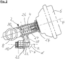
- Fig. 2 shows a further sectional view of a preferred embodiment of the carrier unit 2 according to the invention, wherein, in contrast to the in Fig. 1 shown Embodiment, the carrier unit 2 has two holding portions 28 which are each provided substantially parallel to each other between the guide portion 26 and the first flange portion 22 of the support unit.
- the carrier unit 2 is not partially solid, but is designed as a hollow body or web-like, the weight of the carrier unit 2 can be significantly reduced at the same time to be absorbed by the web-like holding portions 28 of the carrier unit 2 bending moments.
- the carrier unit 2 is not partially solid, but is designed as a hollow body or web-like, the weight of the carrier unit 2 can be significantly reduced at the same time to be absorbed by the web-like holding portions 28 of the carrier unit 2 bending moments.
- the first engagement portion 23 is designed as a threaded bore, in which a securing element 10 can be reached from the side of the carrier unit 2, on which the Sp Drkeiliser 8 is located.
- the securing element 10 then reachable, preferably in the left part of Fig. 2 arranged brake drum (not shown) was dismantled from the brake system.
- the second flange portion 24 has an extension parallel to the guide axis F of approximately up to 30 mm, particularly preferably 14-16 mm, wherein for the tested in the present invention ranges reaches the required strength and at the same time the weight fraction of the second Flange portion 24 could be kept low.
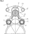
- Fig. 3 shows a sectional view of the already in Fig. 2 illustrated preferred embodiment of the carrier unit 2, wherein in Fig. 3 the sectional plane extends transversely to the engagement axis E.
- the carrier unit 2 not only along the engagement plane E has at least one, preferably two holding sections 28, but also transversely to the engagement direction E offset to each other preferably two holding sections 28 are provided.
- the carrier unit 2 has two first flange portions 22, which are spaced apart from each other and can be fixed to a respectively provided corresponding geometry of the chassis of the commercial vehicle.
- the cylindrical shape of the guide geometry 27 of the guide portion 26 can be seen, in which the guide element 4 is slidably disposed.
- the connection of the holding sections 28 to the guide portion 26 and the respective first flange portion 22 is characterized by rounded outer geometries, which allow a particularly favorable flow of force and avoid notch effects.
- the second flange portion 24 can be seen, which preferably has two spaced apart second engagement geometries, which are advantageously formed as through holes through which a corresponding bolt can be pushed through and in this way a brake cylinder with two attachment points on the second flange 24 can be fixed.
- the two second engagement geometries 25 are at a distance from one another which is at a ratio of 0.9-1.1, preferably 0.95-1.05, to the distance between the two first engagement geometries 23.
- the distance of the two second engagement geometries 25 is substantially equal to the distance of the first engagement geometries 23 to each other.
Landscapes
- Engineering & Computer Science (AREA)
- General Engineering & Computer Science (AREA)
- Mechanical Engineering (AREA)
- Transportation (AREA)
- Braking Arrangements (AREA)
- Body Structure For Vehicles (AREA)
Claims (10)
- Unité de support (2) comportant une première portion de bride (22), une seconde portion de bride (24) et une portion de guidage (26),
dans laquelle
la première portion de bride (22) présente une première géométrie d'engagement (23) pour immobiliser l'unité de support (2) sur un train de roulement,
la seconde portion de bride (24) présente une seconde géométrie d'engagement (25) pour immobiliser un cylindre de frein (6),
la portion de guidage (26) est agencée au voisinage de la seconde portion de bride (24) et présente une géométrie de guidage (27) pour guider un élément de guidage (4) le long d'un axe de guidage (F),
un ensemble à coin d'écartement (8) est prévu au voisinage de la portion de guidage (26),
caractérisée en ce que l'ensemble à coin d'écartement (8) présente un boîtier (82) qui est réalisé d'un seul tenant avec la portion de guidage (26). - Unité de support (2) selon la revendication 1,
dans laquelle la seconde portion de bride (24) est réalisée d'un seul tenant avec la portion de guidage (26). - Unité de support (2) selon l'une des revendications 1 ou 2,
comprenant une portion de retenue (28) qui est adjacente à la première portion de bride (22) et à la portion de guidage (26) et qui s'étend sensiblement le long d'un axe de retenue (H),
la première portion de bride (22), la portion de retenue (28) et la portion de guidage (24) étant réalisées d'un seul tenant les unes avec les autres. - Unité de support (2) selon la revendication 3,
dans laquelle l'axe de retenue (H) est transversal par rapport à l'axe de guidage (F). - Unité de support (2) selon la revendication 3 ou 4,
dans laquelle
la première géométrie d'engagement (23) s'étend sensiblement le long d'un axe d'engagement (E),
l'axe de retenue (H) est pivoté d'un angle (α) par rapport à l'axe d'engagement (E), l'angle (α) étant inférieur à 90°. - Unité de support (2) selon la revendication 5,
dans laquelle l'angle (α) est dans la plage de 45° à 89°, de préférence dans la plage de 60° à 85° et de manière particulièrement préférée d'environ 70° à 85°. - Unité de support selon l'une des revendications précédentes, dans laquelle
il est prévu un élément de blocage (10) qui peut être amené en engagement par coopération de formes avec la première géométrie d'engagement le long d'un axe d'engagement (E),
l'élément de blocage (10) est accessible depuis le côté de l'unité de support (2) sur lequel se situe l'ensemble à coin d'écartement (8). - Unité de support (2) selon l'une des revendications précédentes, dans laquelle
la première portion de bride (22) présente deux géométries d'engagement (23) qui sont agencées à distance l'une de l'autre,
les axes d'engagement (E) des géométries d'engagement (23) s'étendent parallèlement l'un à l'autre. - Unité de support (2) selon la revendication 8,
dans laquelle
il est prévu deux portions de retenue (28) qui sont séparées l'une de l'autre par un espace libre (29),
la surface de section transversale moyenne des portions de retenue (28) est dans une relation de 0,2 à 1,3, de préférence de 0,3 à 0,9 et de manière particulièrement préférée d'environ 0,5 à 0,8 par rapport à la surface de section transversale moyenne de l'espace libre (29). - Unité de support (2) selon l'une des revendications précédentes,
comprenant pas plus de quatre premières géométries d'engagement (23), de préférence pas plus de deux premières géométries d'engagement (23).
Priority Applications (1)
| Application Number | Priority Date | Filing Date | Title |
|---|---|---|---|
| PL15723909T PL3146228T3 (pl) | 2014-05-20 | 2015-05-18 | Jednostka nośna |
Applications Claiming Priority (2)
| Application Number | Priority Date | Filing Date | Title |
|---|---|---|---|
| DE102014209502.6A DE102014209502B4 (de) | 2014-05-20 | 2014-05-20 | Trägereinheit |
| PCT/EP2015/060850 WO2015177073A1 (fr) | 2014-05-20 | 2015-05-18 | Ensemble support |
Publications (3)
| Publication Number | Publication Date |
|---|---|
| EP3146228A1 EP3146228A1 (fr) | 2017-03-29 |
| EP3146228B1 true EP3146228B1 (fr) | 2017-09-13 |
| EP3146228B2 EP3146228B2 (fr) | 2024-01-17 |
Family
ID=53199977
Family Applications (1)
| Application Number | Title | Priority Date | Filing Date |
|---|---|---|---|
| EP15723909.6A Active EP3146228B2 (fr) | 2014-05-20 | 2015-05-18 | Support de frein |
Country Status (10)
| Country | Link |
|---|---|
| US (1) | US10232837B2 (fr) |
| EP (1) | EP3146228B2 (fr) |
| CN (1) | CN106460972B (fr) |
| AU (1) | AU2015263261B2 (fr) |
| CA (1) | CA2949578C (fr) |
| DE (1) | DE102014209502B4 (fr) |
| MX (1) | MX373346B (fr) |
| PL (1) | PL3146228T3 (fr) |
| RU (1) | RU2651450C1 (fr) |
| WO (1) | WO2015177073A1 (fr) |
Citations (5)
| Publication number | Priority date | Publication date | Assignee | Title |
|---|---|---|---|---|
| US3322241A (en) | 1966-01-24 | 1967-05-30 | Rockwell Standard Co | Brake system |
| DE2550855A1 (de) | 1974-11-15 | 1976-05-20 | Girling Ltd | Betaetigungsvorrichtung fuer fahrzeugbremsen |
| US4621713A (en) | 1984-02-29 | 1986-11-11 | Societe Anonyme D.B.A. | Actuating mechanism for a disc brake |
| WO2013087737A1 (fr) | 2011-12-16 | 2013-06-20 | Saf-Holland Gmbh | Support de frein |
| DE102011088847A1 (de) | 2011-12-16 | 2013-06-20 | Saf-Holland Gmbh | Bremssystem einer Trommelbremse |
Family Cites Families (24)
| Publication number | Priority date | Publication date | Assignee | Title |
|---|---|---|---|---|
| US3136227A (en) * | 1960-08-29 | 1964-06-09 | Rockwell Standard Co | Brake operating mechanism |
| US3269492A (en) * | 1963-06-06 | 1966-08-30 | Rockwell Standard Co | Guide and centering means for a brake actuating rod |
| GB1152938A (en) * | 1967-03-02 | 1969-05-21 | Teves Gmbh Alfred | Improvements in or relating to Disc Brakes |
| US3599763A (en) * | 1970-01-26 | 1971-08-17 | Bendix Corp | Anchor piston for wedge brake |
| GB1418630A (en) | 1971-12-16 | 1975-12-24 | Automotive Prod Co Ltd | Internal shoe drum brakes and to fluid pressure braking systems including such brakes |
| GB2015098B (en) * | 1978-02-22 | 1982-04-28 | Girling Ltd | Drum brakes for vehicles |
| BR8005530A (pt) * | 1979-08-31 | 1981-03-17 | Lucas Industries Ltd | Freio de tambor-sapatas internas para veiculo |
| AU545708B2 (en) * | 1980-12-09 | 1985-07-25 | Automotive Products Ltd. | Hydraulic wheel cylinder assemblies |
| US4519482A (en) * | 1982-02-05 | 1985-05-28 | Allied Corporation | Wedge actuated drum brake assembly |
| US4445597A (en) * | 1982-06-17 | 1984-05-01 | Eaton Corporation | Spider assembly for drum brake |
| FR2590219B1 (fr) * | 1985-11-20 | 1991-02-01 | Bendix France | Dispositif de freinage electrique pour vehicule |
| GB8927638D0 (en) * | 1989-12-07 | 1990-02-07 | Rubery Owen Rockwell Ltd | Brake assemblies |
| CA2030315A1 (fr) * | 1990-06-26 | 1991-12-27 | Sung J. Cho | Systeme de freinage a joint a croisillon |
| US5613577A (en) | 1994-12-09 | 1997-03-25 | Ford Motor Company | Automotive disc brake with improved caliper assembly |
| US6247560B1 (en) * | 1996-12-12 | 2001-06-19 | Federal-Mogul Technology Limited | Slidable brake disc system |
| JP2001107999A (ja) * | 1999-10-07 | 2001-04-17 | Nisshinbo Ind Inc | ドラムブレーキ装置 |
| RU2340484C1 (ru) * | 2007-06-19 | 2008-12-10 | Открытое акционерное общество "РИТМ" ТПТА | Тройник для тормозной магистрали подвижного состава |
| US20100193303A1 (en) * | 2009-02-05 | 2010-08-05 | Bendix Spicer Foundation Brake Llc | Brake spider weldment and anchor pin assembly |
| DE102011088848B4 (de) * | 2011-12-16 | 2015-05-13 | Saf-Holland Gmbh | Bremssystem für Nutzfahrzeuge |
| SE537115C2 (sv) * | 2012-07-05 | 2015-01-20 | Scania Cv Ab | Lagerkonsolkonfiguration för trumbroms och metod för montering av en lagerkonsolkonfiguration |
| BR112015031896A2 (pt) * | 2013-07-12 | 2017-07-25 | Hendrickson Usa Llc | suporte angular para freio do eixo de roda para eixo de roda de parede fina |
| US9677628B2 (en) * | 2013-09-16 | 2017-06-13 | Arvinmeritor Technology, Llc | Drum brake assembly and method of manufacture |
| GB2524876A (en) * | 2014-02-14 | 2015-10-07 | Tse Brakes Inc | Pivoting air chamber for braking system |
| US9574626B1 (en) * | 2015-07-28 | 2017-02-21 | Bendix Spicer Foundation Brake Llc | Rigid bracket assembly for mounting a brake assembly and brake actuator |
-
2014
- 2014-05-20 DE DE102014209502.6A patent/DE102014209502B4/de not_active Expired - Fee Related
-
2015
- 2015-05-18 PL PL15723909T patent/PL3146228T3/pl unknown
- 2015-05-18 AU AU2015263261A patent/AU2015263261B2/en not_active Ceased
- 2015-05-18 MX MX2016015224A patent/MX373346B/es active IP Right Grant
- 2015-05-18 CA CA2949578A patent/CA2949578C/fr not_active Expired - Fee Related
- 2015-05-18 US US15/312,112 patent/US10232837B2/en not_active Expired - Fee Related
- 2015-05-18 WO PCT/EP2015/060850 patent/WO2015177073A1/fr not_active Ceased
- 2015-05-18 CN CN201580027272.3A patent/CN106460972B/zh not_active Expired - Fee Related
- 2015-05-18 RU RU2016148464A patent/RU2651450C1/ru not_active IP Right Cessation
- 2015-05-18 EP EP15723909.6A patent/EP3146228B2/fr active Active
Patent Citations (5)
| Publication number | Priority date | Publication date | Assignee | Title |
|---|---|---|---|---|
| US3322241A (en) | 1966-01-24 | 1967-05-30 | Rockwell Standard Co | Brake system |
| DE2550855A1 (de) | 1974-11-15 | 1976-05-20 | Girling Ltd | Betaetigungsvorrichtung fuer fahrzeugbremsen |
| US4621713A (en) | 1984-02-29 | 1986-11-11 | Societe Anonyme D.B.A. | Actuating mechanism for a disc brake |
| WO2013087737A1 (fr) | 2011-12-16 | 2013-06-20 | Saf-Holland Gmbh | Support de frein |
| DE102011088847A1 (de) | 2011-12-16 | 2013-06-20 | Saf-Holland Gmbh | Bremssystem einer Trommelbremse |
Also Published As
| Publication number | Publication date |
|---|---|
| WO2015177073A1 (fr) | 2015-11-26 |
| EP3146228B2 (fr) | 2024-01-17 |
| DE102014209502B4 (de) | 2020-12-10 |
| RU2651450C1 (ru) | 2018-04-19 |
| CN106460972B (zh) | 2018-10-09 |
| EP3146228A1 (fr) | 2017-03-29 |
| MX373346B (es) | 2020-07-06 |
| PL3146228T3 (pl) | 2018-03-30 |
| AU2015263261B2 (en) | 2017-07-13 |
| CN106460972A (zh) | 2017-02-22 |
| US10232837B2 (en) | 2019-03-19 |
| CA2949578A1 (fr) | 2015-11-26 |
| AU2015263261A1 (en) | 2016-12-15 |
| US20170120883A1 (en) | 2017-05-04 |
| CA2949578C (fr) | 2018-10-30 |
| DE102014209502A1 (de) | 2015-11-26 |
| MX2016015224A (es) | 2017-03-23 |
Similar Documents
| Publication | Publication Date | Title |
|---|---|---|
| DE102011000626B4 (de) | Radlagerung für ein Fahrzeugrad sowie Radnabe für die Befestigung eines Fahrzeugrades | |
| EP3057395B1 (fr) | Pointe de soc ou combinaison d'outil ayant une pointe de soc | |
| EP3649354B1 (fr) | Système de fixation d'un axe de pivotement à un châssis de véhicule | |
| DE69011279T2 (de) | Räder mit eingebauten Bremsscheiben. | |
| EP2903838B1 (fr) | Unité de direction | |
| EP1507986A1 (fr) | Frein a disque pourvu d'un etrier flottant et de plusieurs plaquettes de frein exterieures directement supportees contre la flasque de frein | |
| EP3039311B1 (fr) | Unité de freinage | |
| EP3606767B1 (fr) | Système d'essieu | |
| EP2632741B1 (fr) | Système d'essieu | |
| EP3109499B1 (fr) | Frein a disque, en particulier pour vehicules utilitaires | |
| EP3146228B1 (fr) | Support de frein | |
| EP3191326B1 (fr) | Unité d'essieu | |
| DE102005059247B4 (de) | Bremsvorrichtung | |
| EP3638918B1 (fr) | Corps de bague de friction, ensemble de bagues de friction à agencer sur l'âme de roue d'une roue ferroviaire, ainsi que frein de roue ferroviaire | |
| EP3601834B1 (fr) | Dispositif de connection et procédé pour connecter un disc de frein avec un moyeu | |
| WO2017080794A1 (fr) | Système de roulement de roue et procédé de montage d'un système de roulement de roue | |
| EP3512731B1 (fr) | Système d'essieu | |
| DE102005026720A1 (de) | Scheibenbremse für ein Landfahrzeug | |
| WO2016066405A1 (fr) | Frein à disque pour véhicule utilitaire | |
| EP3180537B1 (fr) | Ensemble de freinage et procédé d'entretien d'un ensemble de freinage | |
| DE102012112362C5 (de) | Ventil mit einer Befestigungseinrichtung | |
| DE102007017700A1 (de) | Verliersicherung für eine Nutmutter bei einer Welle-Nabe-Verbindung | |
| DE102016117164B4 (de) | Achssystem | |
| DE102013207314B4 (de) | Achskörper und Fahrwerkseinheit | |
| EP2751439B2 (fr) | Système de freinage d'un frein à tambour |
Legal Events
| Date | Code | Title | Description |
|---|---|---|---|
| STAA | Information on the status of an ep patent application or granted ep patent |
Free format text: STATUS: THE INTERNATIONAL PUBLICATION HAS BEEN MADE |
|
| PUAI | Public reference made under article 153(3) epc to a published international application that has entered the european phase |
Free format text: ORIGINAL CODE: 0009012 |
|
| STAA | Information on the status of an ep patent application or granted ep patent |
Free format text: STATUS: REQUEST FOR EXAMINATION WAS MADE |
|
| 17P | Request for examination filed |
Effective date: 20161209 |
|
| AK | Designated contracting states |
Kind code of ref document: A1 Designated state(s): AL AT BE BG CH CY CZ DE DK EE ES FI FR GB GR HR HU IE IS IT LI LT LU LV MC MK MT NL NO PL PT RO RS SE SI SK SM TR |
|
| AX | Request for extension of the european patent |
Extension state: BA ME |
|
| GRAP | Despatch of communication of intention to grant a patent |
Free format text: ORIGINAL CODE: EPIDOSNIGR1 |
|
| STAA | Information on the status of an ep patent application or granted ep patent |
Free format text: STATUS: GRANT OF PATENT IS INTENDED |
|
| DAV | Request for validation of the european patent (deleted) | ||
| DAX | Request for extension of the european patent (deleted) | ||
| INTG | Intention to grant announced |
Effective date: 20170529 |
|
| GRAS | Grant fee paid |
Free format text: ORIGINAL CODE: EPIDOSNIGR3 |
|
| GRAA | (expected) grant |
Free format text: ORIGINAL CODE: 0009210 |
|
| STAA | Information on the status of an ep patent application or granted ep patent |
Free format text: STATUS: THE PATENT HAS BEEN GRANTED |
|
| AK | Designated contracting states |
Kind code of ref document: B1 Designated state(s): AL AT BE BG CH CY CZ DE DK EE ES FI FR GB GR HR HU IE IS IT LI LT LU LV MC MK MT NL NO PL PT RO RS SE SI SK SM TR |
|
| REG | Reference to a national code |
Ref country code: GB Ref legal event code: FG4D Free format text: NOT ENGLISH |
|
| REG | Reference to a national code |
Ref country code: CH Ref legal event code: EP |
|
| REG | Reference to a national code |
Ref country code: IE Ref legal event code: FG4D Free format text: LANGUAGE OF EP DOCUMENT: GERMAN |
|
| REG | Reference to a national code |
Ref country code: AT Ref legal event code: REF Ref document number: 928468 Country of ref document: AT Kind code of ref document: T Effective date: 20171015 |
|
| REG | Reference to a national code |
Ref country code: DE Ref legal event code: R096 Ref document number: 502015001906 Country of ref document: DE |
|
| REG | Reference to a national code |
Ref country code: SE Ref legal event code: TRGR |
|
| REG | Reference to a national code |
Ref country code: NL Ref legal event code: MP Effective date: 20170913 |
|
| REG | Reference to a national code |
Ref country code: LT Ref legal event code: MG4D |
|
| PG25 | Lapsed in a contracting state [announced via postgrant information from national office to epo] |
Ref country code: FI Free format text: LAPSE BECAUSE OF FAILURE TO SUBMIT A TRANSLATION OF THE DESCRIPTION OR TO PAY THE FEE WITHIN THE PRESCRIBED TIME-LIMIT Effective date: 20170913 Ref country code: HR Free format text: LAPSE BECAUSE OF FAILURE TO SUBMIT A TRANSLATION OF THE DESCRIPTION OR TO PAY THE FEE WITHIN THE PRESCRIBED TIME-LIMIT Effective date: 20170913 Ref country code: LT Free format text: LAPSE BECAUSE OF FAILURE TO SUBMIT A TRANSLATION OF THE DESCRIPTION OR TO PAY THE FEE WITHIN THE PRESCRIBED TIME-LIMIT Effective date: 20170913 Ref country code: NO Free format text: LAPSE BECAUSE OF FAILURE TO SUBMIT A TRANSLATION OF THE DESCRIPTION OR TO PAY THE FEE WITHIN THE PRESCRIBED TIME-LIMIT Effective date: 20171213 |
|
| PG25 | Lapsed in a contracting state [announced via postgrant information from national office to epo] |
Ref country code: LV Free format text: LAPSE BECAUSE OF FAILURE TO SUBMIT A TRANSLATION OF THE DESCRIPTION OR TO PAY THE FEE WITHIN THE PRESCRIBED TIME-LIMIT Effective date: 20170913 Ref country code: GR Free format text: LAPSE BECAUSE OF FAILURE TO SUBMIT A TRANSLATION OF THE DESCRIPTION OR TO PAY THE FEE WITHIN THE PRESCRIBED TIME-LIMIT Effective date: 20171214 Ref country code: BG Free format text: LAPSE BECAUSE OF FAILURE TO SUBMIT A TRANSLATION OF THE DESCRIPTION OR TO PAY THE FEE WITHIN THE PRESCRIBED TIME-LIMIT Effective date: 20171213 Ref country code: ES Free format text: LAPSE BECAUSE OF FAILURE TO SUBMIT A TRANSLATION OF THE DESCRIPTION OR TO PAY THE FEE WITHIN THE PRESCRIBED TIME-LIMIT Effective date: 20170913 Ref country code: RS Free format text: LAPSE BECAUSE OF FAILURE TO SUBMIT A TRANSLATION OF THE DESCRIPTION OR TO PAY THE FEE WITHIN THE PRESCRIBED TIME-LIMIT Effective date: 20170913 |
|
| PG25 | Lapsed in a contracting state [announced via postgrant information from national office to epo] |
Ref country code: NL Free format text: LAPSE BECAUSE OF FAILURE TO SUBMIT A TRANSLATION OF THE DESCRIPTION OR TO PAY THE FEE WITHIN THE PRESCRIBED TIME-LIMIT Effective date: 20170913 |
|
| PG25 | Lapsed in a contracting state [announced via postgrant information from national office to epo] |
Ref country code: CZ Free format text: LAPSE BECAUSE OF FAILURE TO SUBMIT A TRANSLATION OF THE DESCRIPTION OR TO PAY THE FEE WITHIN THE PRESCRIBED TIME-LIMIT Effective date: 20170913 |
|
| REG | Reference to a national code |
Ref country code: FR Ref legal event code: PLFP Year of fee payment: 4 |
|
| PG25 | Lapsed in a contracting state [announced via postgrant information from national office to epo] |
Ref country code: SK Free format text: LAPSE BECAUSE OF FAILURE TO SUBMIT A TRANSLATION OF THE DESCRIPTION OR TO PAY THE FEE WITHIN THE PRESCRIBED TIME-LIMIT Effective date: 20170913 Ref country code: IS Free format text: LAPSE BECAUSE OF FAILURE TO SUBMIT A TRANSLATION OF THE DESCRIPTION OR TO PAY THE FEE WITHIN THE PRESCRIBED TIME-LIMIT Effective date: 20180113 Ref country code: SM Free format text: LAPSE BECAUSE OF FAILURE TO SUBMIT A TRANSLATION OF THE DESCRIPTION OR TO PAY THE FEE WITHIN THE PRESCRIBED TIME-LIMIT Effective date: 20170913 Ref country code: IT Free format text: LAPSE BECAUSE OF FAILURE TO SUBMIT A TRANSLATION OF THE DESCRIPTION OR TO PAY THE FEE WITHIN THE PRESCRIBED TIME-LIMIT Effective date: 20170913 Ref country code: EE Free format text: LAPSE BECAUSE OF FAILURE TO SUBMIT A TRANSLATION OF THE DESCRIPTION OR TO PAY THE FEE WITHIN THE PRESCRIBED TIME-LIMIT Effective date: 20170913 |
|
| REG | Reference to a national code |
Ref country code: DE Ref legal event code: R026 Ref document number: 502015001906 Country of ref document: DE |
|
| PLBI | Opposition filed |
Free format text: ORIGINAL CODE: 0009260 |
|
| PLAX | Notice of opposition and request to file observation + time limit sent |
Free format text: ORIGINAL CODE: EPIDOSNOBS2 |
|
| PLAB | Opposition data, opponent's data or that of the opponent's representative modified |
Free format text: ORIGINAL CODE: 0009299OPPO |
|
| 26 | Opposition filed |
Opponent name: KNOTT GMBH Effective date: 20180612 |
|
| PLBB | Reply of patent proprietor to notice(s) of opposition received |
Free format text: ORIGINAL CODE: EPIDOSNOBS3 |
|
| PG25 | Lapsed in a contracting state [announced via postgrant information from national office to epo] |
Ref country code: DK Free format text: LAPSE BECAUSE OF FAILURE TO SUBMIT A TRANSLATION OF THE DESCRIPTION OR TO PAY THE FEE WITHIN THE PRESCRIBED TIME-LIMIT Effective date: 20170913 |
|
| R26 | Opposition filed (corrected) |
Opponent name: KNOTT GMBH Effective date: 20180612 |
|
| PG25 | Lapsed in a contracting state [announced via postgrant information from national office to epo] |
Ref country code: MT Free format text: LAPSE BECAUSE OF FAILURE TO SUBMIT A TRANSLATION OF THE DESCRIPTION OR TO PAY THE FEE WITHIN THE PRESCRIBED TIME-LIMIT Effective date: 20170913 |
|
| REG | Reference to a national code |
Ref country code: CH Ref legal event code: PL |
|
| REG | Reference to a national code |
Ref country code: BE Ref legal event code: MM Effective date: 20180531 |
|
| PG25 | Lapsed in a contracting state [announced via postgrant information from national office to epo] |
Ref country code: MC Free format text: LAPSE BECAUSE OF FAILURE TO SUBMIT A TRANSLATION OF THE DESCRIPTION OR TO PAY THE FEE WITHIN THE PRESCRIBED TIME-LIMIT Effective date: 20170913 |
|
| REG | Reference to a national code |
Ref country code: IE Ref legal event code: MM4A |
|
| PG25 | Lapsed in a contracting state [announced via postgrant information from national office to epo] |
Ref country code: CH Free format text: LAPSE BECAUSE OF NON-PAYMENT OF DUE FEES Effective date: 20180531 Ref country code: LI Free format text: LAPSE BECAUSE OF NON-PAYMENT OF DUE FEES Effective date: 20180531 |
|
| PG25 | Lapsed in a contracting state [announced via postgrant information from national office to epo] |
Ref country code: LU Free format text: LAPSE BECAUSE OF NON-PAYMENT OF DUE FEES Effective date: 20180518 |
|
| PG25 | Lapsed in a contracting state [announced via postgrant information from national office to epo] |
Ref country code: IE Free format text: LAPSE BECAUSE OF NON-PAYMENT OF DUE FEES Effective date: 20180518 |
|
| PG25 | Lapsed in a contracting state [announced via postgrant information from national office to epo] |
Ref country code: BE Free format text: LAPSE BECAUSE OF NON-PAYMENT OF DUE FEES Effective date: 20180531 |
|
| PGFP | Annual fee paid to national office [announced via postgrant information from national office to epo] |
Ref country code: SE Payment date: 20190513 Year of fee payment: 8 |
|
| PGFP | Annual fee paid to national office [announced via postgrant information from national office to epo] |
Ref country code: GB Payment date: 20190523 Year of fee payment: 5 |
|
| PG25 | Lapsed in a contracting state [announced via postgrant information from national office to epo] |
Ref country code: PT Free format text: LAPSE BECAUSE OF FAILURE TO SUBMIT A TRANSLATION OF THE DESCRIPTION OR TO PAY THE FEE WITHIN THE PRESCRIBED TIME-LIMIT Effective date: 20170913 |
|
| PG25 | Lapsed in a contracting state [announced via postgrant information from national office to epo] |
Ref country code: HU Free format text: LAPSE BECAUSE OF FAILURE TO SUBMIT A TRANSLATION OF THE DESCRIPTION OR TO PAY THE FEE WITHIN THE PRESCRIBED TIME-LIMIT; INVALID AB INITIO Effective date: 20150518 Ref country code: RO Free format text: LAPSE BECAUSE OF FAILURE TO SUBMIT A TRANSLATION OF THE DESCRIPTION OR TO PAY THE FEE WITHIN THE PRESCRIBED TIME-LIMIT Effective date: 20170913 Ref country code: CY Free format text: LAPSE BECAUSE OF FAILURE TO SUBMIT A TRANSLATION OF THE DESCRIPTION OR TO PAY THE FEE WITHIN THE PRESCRIBED TIME-LIMIT Effective date: 20170913 Ref country code: MK Free format text: LAPSE BECAUSE OF NON-PAYMENT OF DUE FEES Effective date: 20170913 |
|
| PG25 | Lapsed in a contracting state [announced via postgrant information from national office to epo] |
Ref country code: AL Free format text: LAPSE BECAUSE OF FAILURE TO SUBMIT A TRANSLATION OF THE DESCRIPTION OR TO PAY THE FEE WITHIN THE PRESCRIBED TIME-LIMIT Effective date: 20170913 |
|
| PGFP | Annual fee paid to national office [announced via postgrant information from national office to epo] |
Ref country code: FR Payment date: 20200519 Year of fee payment: 6 Ref country code: TR Payment date: 20200515 Year of fee payment: 6 |
|
| APBM | Appeal reference recorded |
Free format text: ORIGINAL CODE: EPIDOSNREFNO |
|
| APBP | Date of receipt of notice of appeal recorded |
Free format text: ORIGINAL CODE: EPIDOSNNOA2O |
|
| APAH | Appeal reference modified |
Free format text: ORIGINAL CODE: EPIDOSCREFNO |
|
| PG25 | Lapsed in a contracting state [announced via postgrant information from national office to epo] |
Ref country code: SI Free format text: LAPSE BECAUSE OF NON-PAYMENT OF DUE FEES Effective date: 20180518 |
|
| APBQ | Date of receipt of statement of grounds of appeal recorded |
Free format text: ORIGINAL CODE: EPIDOSNNOA3O |
|
| GBPC | Gb: european patent ceased through non-payment of renewal fee |
Effective date: 20200518 |
|
| PG25 | Lapsed in a contracting state [announced via postgrant information from national office to epo] |
Ref country code: GB Free format text: LAPSE BECAUSE OF NON-PAYMENT OF DUE FEES Effective date: 20200518 |
|
| REG | Reference to a national code |
Ref country code: AT Ref legal event code: MM01 Ref document number: 928468 Country of ref document: AT Kind code of ref document: T Effective date: 20200518 |
|
| PG25 | Lapsed in a contracting state [announced via postgrant information from national office to epo] |
Ref country code: AT Free format text: LAPSE BECAUSE OF NON-PAYMENT OF DUE FEES Effective date: 20200518 |
|
| REG | Reference to a national code |
Ref country code: SE Ref legal event code: EUG |
|
| PG25 | Lapsed in a contracting state [announced via postgrant information from national office to epo] |
Ref country code: SE Free format text: LAPSE BECAUSE OF NON-PAYMENT OF DUE FEES Effective date: 20210519 |
|
| PG25 | Lapsed in a contracting state [announced via postgrant information from national office to epo] |
Ref country code: FR Free format text: LAPSE BECAUSE OF NON-PAYMENT OF DUE FEES Effective date: 20210531 |
|
| PG25 | Lapsed in a contracting state [announced via postgrant information from national office to epo] |
Ref country code: PL Free format text: LAPSE BECAUSE OF NON-PAYMENT OF DUE FEES Effective date: 20200518 |
|
| APAH | Appeal reference modified |
Free format text: ORIGINAL CODE: EPIDOSCREFNO |
|
| P01 | Opt-out of the competence of the unified patent court (upc) registered |
Effective date: 20230505 |
|
| APBU | Appeal procedure closed |
Free format text: ORIGINAL CODE: EPIDOSNNOA9O |
|
| PUAH | Patent maintained in amended form |
Free format text: ORIGINAL CODE: 0009272 |
|
| STAA | Information on the status of an ep patent application or granted ep patent |
Free format text: STATUS: PATENT MAINTAINED AS AMENDED |
|
| 27A | Patent maintained in amended form |
Effective date: 20240117 |
|
| AK | Designated contracting states |
Kind code of ref document: B2 Designated state(s): AL AT BE BG CH CY CZ DE DK EE ES FI FR GB GR HR HU IE IS IT LI LT LU LV MC MK MT NL NO PL PT RO RS SE SI SK SM TR |
|
| REG | Reference to a national code |
Ref country code: DE Ref legal event code: R102 Ref document number: 502015001906 Country of ref document: DE |
|
| PGFP | Annual fee paid to national office [announced via postgrant information from national office to epo] |
Ref country code: DE Payment date: 20250221 Year of fee payment: 11 |