EP3146825A1 - Système d'assistance du conducteur pour machine de travail agricole - Google Patents
Système d'assistance du conducteur pour machine de travail agricole Download PDFInfo
- Publication number
- EP3146825A1 EP3146825A1 EP16176887.4A EP16176887A EP3146825A1 EP 3146825 A1 EP3146825 A1 EP 3146825A1 EP 16176887 A EP16176887 A EP 16176887A EP 3146825 A1 EP3146825 A1 EP 3146825A1
- Authority
- EP
- European Patent Office
- Prior art keywords
- lane
- working
- inventory
- turning
- assistance system
- Prior art date
- Legal status (The legal status is an assumption and is not a legal conclusion. Google has not performed a legal analysis and makes no representation as to the accuracy of the status listed.)
- Granted
Links
Images

Classifications
-
- A—HUMAN NECESSITIES
- A01—AGRICULTURE; FORESTRY; ANIMAL HUSBANDRY; HUNTING; TRAPPING; FISHING
- A01B—SOIL WORKING IN AGRICULTURE OR FORESTRY; PARTS, DETAILS, OR ACCESSORIES OF AGRICULTURAL MACHINES OR IMPLEMENTS, IN GENERAL
- A01B69/00—Steering of agricultural machines or implements; Guiding agricultural machines or implements on a desired track
- A01B69/007—Steering or guiding of agricultural vehicles, e.g. steering of the tractor to keep the plough in the furrow
- A01B69/008—Steering or guiding of agricultural vehicles, e.g. steering of the tractor to keep the plough in the furrow automatic
Definitions
- the invention relates to a driver assistance system for an agricultural work machine according to the preamble of claim 1 and to a method for operating an agricultural work machine according to the preamble of claim 15.
- the known driver assistance system ( DE 10 2013 011 152 A1 ), from which the invention proceeds, is equipped with a tracking control that generates steering commands for the work machine based on a satellite-based navigation system.
- the tracking control allows a corresponding sensor-assisted departure of a turning lane in the context of the turning process, which basically allows a precise adherence to a planned turning lane, which is hereinafter referred to as "plan turning lane".
- plane turning lane a planned turning lane
- the invention is based on the problem of designing and developing the known driver assistance system in such a way that the effectiveness in the processing is increased.
- the use of the inventory edge sensor in the turnaround process ensures that the target work lane is approached at all times, regardless of any unforeseeable influences. This is especially true in cases where during the reversing of the reversing lane unpredictable factors such as slippage or drift of the work machine occur in the headland area in which inaccuracies in the steering system occur or in which the actual position of the target working lane has shifted.
- components of the tracking control can be used twice, here the inventory edge sensor.
- the crop edge sensor preferably serves to detect the respective crop edge along which a work lane is to be traveled.
- the alignment operation in which the work machine is aligned with the target work lane is performed.
- the steering commands are carried out semi-automatically.
- a man-machine interface outputs the generated steering commands for user-side implementation.
- the further preferred embodiments according to claims 10 and 11 show that the alignment process, in particular the detection of the respective reference crop edge, can be triggered in different sections of the turning lane.
- the reference stock edge must already be in the entry area of the stock edge sensor.
- the further preferred embodiment according to claim 14 provides that a turning planning system is provided which generates a plan turning lane from different initial parameters and that the plan turning lane based on the detection of the edge of the target working lane on the actual position of the target Aligning working lane. This aligns the plan reversal track generated offline with the actual geometric conditions in the field inventory. On the one hand, this allows the reversing lane to be optimized for the relevant parameters of the working machine, which is the easiest in offline mode. On the other hand, there are no for an offline generation of lanes typical, geometric deviations from the actual geometric conditions.
- the proposed driver assistance system 1 can be applied to all agricultural machines 2, with which a processing of a field crop 3 in a variety of adjacent working lanes 4 is possible, the change from a working lane 4 to a next working lane requires a turning process.
- the working machine 2 is a combine harvester or a forage harvester.
- the work machine 2 is equipped with an attachment 2 a, which defines the working width 2 b of the work machine 2.
- the attachment 2a includes, inter alia, a cutting unit for cutting the plants present in the field stock 3. In this case, as part of the processing by the departure of the working lanes 4 continuously a new stock edge 9 is generated.
- the driver assistance system 1 is equipped with a tracking control 5.
- the tracking control 5 generates steering commands for the work machine 2 during the turning operation, which form the basis for the automatic or semi-automatic turning of the work machine 2.
- the turning of the working machine 2 takes place according to the proposal in a headland area 6, which is located at an edge of the field stock 3, in which the working lanes 4 open next to each other.
- the turning process comprises a sensor-assisted departure of a turning lane 7 between an exit work lane 4a and a destination work lane 4b offset therefrom, which has a direction of travel opposite to the exit work lane 4a.
- the offset of the working lanes 4 to each other is provided here substantially transversely to the extension of the respective working lane 4.
- the working lanes 4 are preferably formed in a first approximation straight.
- the tracking control 5 generates the above steering commands for the work machine 2 as a basis for the sensor-assisted departure of the turning lane 7.
- the sensor assistance in the departure of the turning lane 7 will be explained in more detail below.
- a stock edge sensor 8 is provided for detecting stock edges 9 in the field stock 3, which is preferably used in several ways. This double use was mentioned above.
- the tracking controller 5 generates, as also mentioned above, steering commands for the work machine 2 in the context of the turning operation. It is essential here that the tracking control 5 carries out an alignment process as part of the turning process, in which it detects a reference crop edge 9b of the field crop 3 by means of the crop edge sensor 8 and, based thereon, aligns the work machine 2 with the target work lane 4b for steering commands Work machine 2 generated.
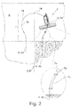
- the work machine 2 during the alignment process is in Fig. 2 shown.
- the driver assistance system 2 detects the position of the reference stock edge 9b by means of the stock edge sensor 8 and aligns the work machine 2 by the generation of appropriate steering commands to the beginning of the target working lane 4b. This makes it possible to drive the work machine 2 into the respective target work lane 4b with pinpoint accuracy.
- the tracking controller 5 preferably also generates steering commands for the work machine 2 during the processing of the field inventory 3.
- the tracking control 5 as part of processing the field inventory 3 supports the departure of the work lanes 4 on global position information of a particular satellite-based navigation system and in the context of the turning operation for aligning the work machine 2 to the local working edge sensor (8) switches.
- the term "global" means that the positioning navigation system does not capture local features of the immediate environment of the work machine 2, but rather position information with a global reference system, such as latitude and longitude position information.
- the tracking control 5 generates steering commands based on the detection of a stock edge 9a by the stock edge sensor 8 during the processing of the crop stock 3, namely for the sensor-assisted departure of work lanes 4 along the relevant stock edge 9a.
- the above offset of the target working lane 4b to the starting working lane 4a may be different depending on the machining strategy.
- the target working lane 4b is offset by a lane width 10 to the original working lane 4a so that the target working lane 4b and the starting working lane 4a are located immediately adjacent to each other.
- the target working lane 4b is offset by a number of track widths 10 to the output working lane 4a.
- the track width 10 is determined here by the working width 2b of the attachment 2a.
- the reference stock edge 9b is preferably a stock edge produced by the removal of the exit work lane 4a during the processing.
- the reference stock edge 9b can also be any other stock edge which is within the detection range of the stock edge sensor 8.
- the steering commands generated by the tracking control 5 can be used in very different ways.
- one of the working machine 2 associated steering system 11 may be provided with a steering drive 12, which converts the steering commands generated in steering movements.
- a steering drive 12 which converts the steering commands generated in steering movements.
- a man-machine interface 13 can be provided, via which the generated steering commands can be output to the user-side conversion.
- the tracking controller 5 may issue correction presets for manual steering via the man-machine interface 13, which the user manually implements accordingly.
- the turning process includes the departure of a turning lane 7 with a vertex 14, in which the direction of travel part along the output working lane 4a reverses.
- the vertex 14 is thus the point at which the working machine 2 no longer moves away from the field stock 3 but towards the field stock 3.
- the turning lane 7 can run so that it can be traversed in a train. It is also conceivable that the turning process provides a turn in several moves. This means that the work machine 2 is reset at least once during the turning process in order to reduce the extent of the turning track 7.
- the alignment process can be applied without restriction to turning in several passes.
- the turning lane 7 preferably has a vertex 14 comprehensive, here and preferably at least partially circular arc section 15, in which the actual turning of the working machine 2 takes place.
- the bow portion 15 closes as in Fig. 2 represented, via a first, here and preferably curved transition section 16 to the output working lane 4a, while in the course of the turning lane 7, the target working lane 4b connects via a second, here and preferably curved transition section 17 to the arc section 15.
- the first transition section 16 in turn, here and preferably adjoins a straight extension section 18, in which the work machine 2 extends out of the exit working lane 4a.
- a straight entry section 19 in which the work machine 2 enters the target working lane 4b.
- the alignment process can be triggered at different points of the turning process, depending on the design of the stock edge sensor 8.
- the alignment process in particular the detection of the reference stock edge 9b, is triggered only after crossing the apex 14.
- This takes into account the fact that the detection area of the crop edge sensor 8 is regularly located in the front area of the work machine 2 in order to be able to detect the future course of the crop edge 9a during processing.
- the alignment process in particular the detection of the reference stock edge 9b, in the second transition section 17 is triggered.
- the stock edge sensor 8 can operate according to different measurement principles.
- the stock edge sensor 8 is a laser-based distance sensor. It can be provided that a laser beam is selectively guided over a predetermined angular range in order to detect the respective stock edge 9.
- the inventory edge sensor 8 is a camera-based sensor.
- the advantage of a camera-based sensor is that it eliminates the need for a beam-guiding device, which is necessary for a laser-based distance sensor.
- the camera-based sensor is a 3D sensor, so that again distances can be determined.
- Other measuring principles can be used for the crop edge sensor 8.
- the tracking control 5 is associated with the driver assistance system 1, but also a turning planning system that generates a plan turnaround lane 7a from various parameters, in particular from the working width 2b of the work machine 2, the minimum steering radius of the work machine 2 and the field geometry in the course of the turning operation, the tracking control controller 5 adjusts the plan turning lane 7a to the actual position of the target working lane 4b based on the detection of the reference standing edge 9b.
- the working machine 2 departs the actual turning lane 7b, which opens into the actual target lane 4b by the above adjustment.
- the actual turning lane 7c would be traversed as in Fig. 2 exemplified. In the latter case, an unprocessed strip would remain in the field inventory, which would reduce the processing efficiency accordingly.
- the plan turning lane 7a is determined by the turning planning system, preferably in the off-line mode, ie in time before the actual turning operation.
- the geometry of the turning lane 7a optimally to the respectively relevant parameters, in particular to the machine and environmental parameters to be optimized.
- the adjustment of this plan turning lane 7a is necessary to adapt the plan turning lane 7a to a possible displacement of the working lanes 4. This is done online, ie during the turning process.
- the structuring of the control of the turning process into an offline section and into an online section leads to a time-efficient method, since all planning steps, which do not necessarily have to be done online, are carried out in offline mode.
- an inventory edge sensor 8 and a tracking control 5 are provided, 9 steering commands for the work machine 2 by means of the tracking control 5 in the context of editing the field inventory 3 for sensor-driven departure of working lanes 4 along a respective stock edge 9 based on the detection of the stock edge be generated and in the context of a turning operation in a headland area 6 by means of the tracking control 5 for sensor-driven departure of a turning lane between an output working lane 4a and this purpose offset work lane 4b with opposite direction steering commands for the machine 2.
- Essential for the proposed method is, as also explained above, that by means of the tracking control 5 in the context of the turning process, an alignment is performed in which by means of the stock edge sensor 8 a reference stock edge 9b of field inventory 3 is detected and based on this for aligning the machine 2 on the target working lane 4b steering commands for the working machine 2 are generated.
Landscapes
- Life Sciences & Earth Sciences (AREA)
- Engineering & Computer Science (AREA)
- Mechanical Engineering (AREA)
- Soil Sciences (AREA)
- Environmental Sciences (AREA)
- Guiding Agricultural Machines (AREA)
Applications Claiming Priority (1)
| Application Number | Priority Date | Filing Date | Title |
|---|---|---|---|
| DE102015115510.9A DE102015115510A1 (de) | 2015-09-15 | 2015-09-15 | Fahrerassistenzsystem für eine landwirtschaftliche Arbeitsmaschine |
Publications (3)
| Publication Number | Publication Date |
|---|---|
| EP3146825A1 true EP3146825A1 (fr) | 2017-03-29 |
| EP3146825B1 EP3146825B1 (fr) | 2021-08-11 |
| EP3146825B2 EP3146825B2 (fr) | 2026-01-07 |
Family
ID=56289429
Family Applications (1)
| Application Number | Title | Priority Date | Filing Date |
|---|---|---|---|
| EP16176887.4A Active EP3146825B2 (fr) | 2015-09-15 | 2016-06-29 | Système d'assistance du conducteur pour machine de travail agricole |
Country Status (2)
| Country | Link |
|---|---|
| EP (1) | EP3146825B2 (fr) |
| DE (1) | DE102015115510A1 (fr) |
Cited By (9)
| Publication number | Priority date | Publication date | Assignee | Title |
|---|---|---|---|---|
| EP3903555A1 (fr) * | 2020-04-30 | 2021-11-03 | Trimble Inc. | Procédé et système de planification des trajectoires de virages suivant une tournière |
| DE102021111360A1 (de) | 2021-05-03 | 2022-11-03 | Maschinenfabrik Bernard Krone GmbH & Co. KG | Lenkverfahren für eine landmaschine |
| US11500390B2 (en) | 2020-04-30 | 2022-11-15 | Trimble Inc. | Multi-segment turns |
| US11814074B2 (en) | 2020-04-30 | 2023-11-14 | Trimble Inc. | Headland-following turns |
| US11874665B2 (en) | 2021-05-24 | 2024-01-16 | Trimble Inc. | Area coverage planner with replenishment planner |
| EP4316230A1 (fr) | 2022-08-02 | 2024-02-07 | Deere & Company | Utilisation de zones de couverture dans la commande d'opérations de machines agricoles |
| US11974520B2 (en) | 2018-02-26 | 2024-05-07 | Deere & Company | Automatic product harvesting control system |
| DE102023119302A1 (de) | 2023-07-21 | 2025-01-23 | Deere & Company | Anordnung zur Führung eines landwirtschaftlichen Fahrzeugs über ein Feld mit Sensorfusion und entsprechendes Verfahren |
| US12582018B2 (en) | 2022-08-02 | 2026-03-24 | Deere & Company | Use of coverage areas in controlling agricultural machine operations |
Families Citing this family (1)
| Publication number | Priority date | Publication date | Assignee | Title |
|---|---|---|---|---|
| EP4544894A1 (fr) * | 2023-10-23 | 2025-04-30 | Deere & Company | Utilisation de zones de couverture dans la commande d'opérations de machines agricoles |
Citations (2)
| Publication number | Priority date | Publication date | Assignee | Title |
|---|---|---|---|---|
| DE102009041646A1 (de) * | 2009-09-17 | 2011-03-24 | Claas Selbstfahrende Erntemaschinen Gmbh | Landwirtschaftliche Maschine mit Autopilot |
| DE102013011152A1 (de) | 2013-07-04 | 2015-01-08 | Claas Selbstfahrende Erntemaschinen Gmbh | Fahrzeug mit mehreren Lenkprogrammen |
Family Cites Families (8)
| Publication number | Priority date | Publication date | Assignee | Title |
|---|---|---|---|---|
| DE19629618A1 (de) | 1996-07-23 | 1998-01-29 | Claas Ohg | Routenplanungssystem für landwirtschaftliche Arbeitsfahrzeuge |
| WO1998046065A1 (fr) | 1997-04-16 | 1998-10-22 | Carnegie Mellon University | Machine agricole de recolte commandee par robot |
| DE10129133A1 (de) * | 2001-06-16 | 2002-12-19 | Deere & Co | Einrichtung zur selbsttätigen Lenkung eines landwirtschaftlichen Arbeitsfahrzeugs |
| DE102004036946A1 (de) * | 2003-10-02 | 2005-05-19 | Claas Selbstfahrende Erntemaschinen Gmbh | Transformationsvorrichtung innerhalb einer landwirtschaftlichen Maschine |
| DE10351861A1 (de) | 2003-11-06 | 2005-06-09 | Deere & Company, Moline | Verfahren und Lenksystem zum selbsttätigen Lenken einer landwirtschaftlichen Maschine |
| US9002566B2 (en) | 2008-02-10 | 2015-04-07 | AgJunction, LLC | Visual, GNSS and gyro autosteering control |
| US8131432B2 (en) * | 2008-02-27 | 2012-03-06 | Deere & Company | Method and system for managing the turning of a vehicle |
| DE102014108346A1 (de) | 2014-06-13 | 2015-12-17 | Claas Selbstfahrende Erntemaschinen Gmbh | Bestandsorientierter Einspurvorgang bei Reihenkulturen |
-
2015
- 2015-09-15 DE DE102015115510.9A patent/DE102015115510A1/de not_active Withdrawn
-
2016
- 2016-06-29 EP EP16176887.4A patent/EP3146825B2/fr active Active
Patent Citations (2)
| Publication number | Priority date | Publication date | Assignee | Title |
|---|---|---|---|---|
| DE102009041646A1 (de) * | 2009-09-17 | 2011-03-24 | Claas Selbstfahrende Erntemaschinen Gmbh | Landwirtschaftliche Maschine mit Autopilot |
| DE102013011152A1 (de) | 2013-07-04 | 2015-01-08 | Claas Selbstfahrende Erntemaschinen Gmbh | Fahrzeug mit mehreren Lenkprogrammen |
Cited By (13)
| Publication number | Priority date | Publication date | Assignee | Title |
|---|---|---|---|---|
| US11974520B2 (en) | 2018-02-26 | 2024-05-07 | Deere & Company | Automatic product harvesting control system |
| US11814074B2 (en) | 2020-04-30 | 2023-11-14 | Trimble Inc. | Headland-following turns |
| EP3903556A1 (fr) * | 2020-04-30 | 2021-11-03 | Trimble Inc. | Procédés de planification des trajectoires de virages à segments multiples |
| EP3903555A1 (fr) * | 2020-04-30 | 2021-11-03 | Trimble Inc. | Procédé et système de planification des trajectoires de virages suivant une tournière |
| US11500390B2 (en) | 2020-04-30 | 2022-11-15 | Trimble Inc. | Multi-segment turns |
| US12085954B2 (en) | 2021-05-03 | 2024-09-10 | Maschinenfabrik Bernard Krone GmbH & Co. KG | Steering method for an agricultural machine |
| EP4085741A1 (fr) | 2021-05-03 | 2022-11-09 | Maschinenfabrik Bernard Krone GmbH & Co. KG | Procédé de direction pour une machine agricole |
| DE102021111360A1 (de) | 2021-05-03 | 2022-11-03 | Maschinenfabrik Bernard Krone GmbH & Co. KG | Lenkverfahren für eine landmaschine |
| US11874665B2 (en) | 2021-05-24 | 2024-01-16 | Trimble Inc. | Area coverage planner with replenishment planner |
| EP4316230A1 (fr) | 2022-08-02 | 2024-02-07 | Deere & Company | Utilisation de zones de couverture dans la commande d'opérations de machines agricoles |
| US12582018B2 (en) | 2022-08-02 | 2026-03-24 | Deere & Company | Use of coverage areas in controlling agricultural machine operations |
| DE102023119302A1 (de) | 2023-07-21 | 2025-01-23 | Deere & Company | Anordnung zur Führung eines landwirtschaftlichen Fahrzeugs über ein Feld mit Sensorfusion und entsprechendes Verfahren |
| US12538859B2 (en) | 2023-07-21 | 2026-02-03 | Deere & Company | Arrangement and method for guiding an agricultural vehicle in a field with sensor fusion |
Also Published As
| Publication number | Publication date |
|---|---|
| DE102015115510A1 (de) | 2017-03-16 |
| EP3146825B1 (fr) | 2021-08-11 |
| EP3146825B2 (fr) | 2026-01-07 |
Similar Documents
| Publication | Publication Date | Title |
|---|---|---|
| EP3146825B1 (fr) | Système d'assistance du conducteur pour machine de travail agricole | |
| EP2125472B1 (fr) | Système semi-automatique de stationnement | |
| EP2828029B1 (fr) | Méthode de découpe de tôles | |
| EP3849740B1 (fr) | Procédé et dispositif pour découper au laser une platine en tôle à partir d'une bande de tôle convoyée en continu | |
| DE102007016913A1 (de) | Verfahren zum Abfahren einer Arbeits-Fläche | |
| EP3363273A1 (fr) | Système de machine agricole et procédé de planification de voies de circulation permettant de traiter une surface agricole | |
| WO2020148047A1 (fr) | Procédé d'entraînement à une trajectoire pour un véhicule, et système électronique de guidage de véhicule | |
| DE102015122149A1 (de) | Verfahren zum autonomen Betrieb einer Verdichtungsvorrichtung | |
| EP3911471B1 (fr) | Procédé de balayage de la surface de pièces métalliques | |
| EP3584041A1 (fr) | Procédé de raccordement de composants | |
| EP3953237A1 (fr) | Procédé pour garer un véhicule d'une traite, système d'aide au stationnement, ainsi que véhicule | |
| EP2983010B1 (fr) | Procede de correction des donnees de position enregistrees dans une memoire d'un ordinateur auxiliaire | |
| WO2020160796A1 (fr) | Procédé et dispositif de fusion de données de capteurs multiples pour des véhicules automatisés et autonomes | |
| DD248159A5 (de) | Verfahren und vorrichtung zur instandsetzung oder verlegung eines eisenbahngleises | |
| DE10229293A1 (de) | Verfahren zur Bestimmung der relativen Orientierung einer Roboter-Verfahrachse gegenüber einem Roboter-Koordinatensystem | |
| DE102021125360A1 (de) | Vorrichtung und Verfahren zur Bestimmung einer Lenkvorgabe für eine landwirtschaftliche Maschine | |
| DE2417289A1 (de) | Kurvenfolgeeinrichtung | |
| WO2020023988A1 (fr) | Procédé de fonctionnement d'une presse plieuse | |
| WO2015118080A1 (fr) | Procédé et dispositif de soudage ou découpe au laser à domaine d'analyse adaptable dynamiquement | |
| DE102017103144A1 (de) | Verfahren und Vorrichtung zur Klassifizierung von Begrenzungsabschnitten einer landwirtschaftlichen Fläche | |
| EP4377180A1 (fr) | Procédé et dispositif pour faire fonctionner un véhicule dans un mode de conduite automatisé | |
| EP2710873B1 (fr) | Dispositif de commande pour une machine de travail agricole | |
| DE2618165C3 (de) | Elektrische Kopiersteuerungsvorrichtung für Bearbeitungsmaschinen | |
| DE102017103142A1 (de) | Verfahren zur Aufteilung einer landwirtschaftlichen Fläche in mehrere Teilflächen | |
| DE102022109922B3 (de) | Bodenbearbeitungsroboter-System, Vorrichtung zur lokalen Veränderung eines Schleifendrahtmagnetfeldes, Erdnagel und Verfahren zur Rückführung eines autonom fahrenden Bodenbearbeitungsroboters |
Legal Events
| Date | Code | Title | Description |
|---|---|---|---|
| PUAI | Public reference made under article 153(3) epc to a published international application that has entered the european phase |
Free format text: ORIGINAL CODE: 0009012 |
|
| STAA | Information on the status of an ep patent application or granted ep patent |
Free format text: STATUS: THE APPLICATION HAS BEEN PUBLISHED |
|
| AK | Designated contracting states |
Kind code of ref document: A1 Designated state(s): AL AT BE BG CH CY CZ DE DK EE ES FI FR GB GR HR HU IE IS IT LI LT LU LV MC MK MT NL NO PL PT RO RS SE SI SK SM TR |
|
| AX | Request for extension of the european patent |
Extension state: BA ME |
|
| STAA | Information on the status of an ep patent application or granted ep patent |
Free format text: STATUS: REQUEST FOR EXAMINATION WAS MADE |
|
| 17P | Request for examination filed |
Effective date: 20170929 |
|
| RBV | Designated contracting states (corrected) |
Designated state(s): AL AT BE BG CH CY CZ DE DK EE ES FI FR GB GR HR HU IE IS IT LI LT LU LV MC MK MT NL NO PL PT RO RS SE SI SK SM TR |
|
| GRAP | Despatch of communication of intention to grant a patent |
Free format text: ORIGINAL CODE: EPIDOSNIGR1 |
|
| STAA | Information on the status of an ep patent application or granted ep patent |
Free format text: STATUS: GRANT OF PATENT IS INTENDED |
|
| INTG | Intention to grant announced |
Effective date: 20210309 |
|
| GRAS | Grant fee paid |
Free format text: ORIGINAL CODE: EPIDOSNIGR3 |
|
| GRAA | (expected) grant |
Free format text: ORIGINAL CODE: 0009210 |
|
| STAA | Information on the status of an ep patent application or granted ep patent |
Free format text: STATUS: THE PATENT HAS BEEN GRANTED |
|
| AK | Designated contracting states |
Kind code of ref document: B1 Designated state(s): AL AT BE BG CH CY CZ DE DK EE ES FI FR GB GR HR HU IE IS IT LI LT LU LV MC MK MT NL NO PL PT RO RS SE SI SK SM TR |
|
| REG | Reference to a national code |
Ref country code: CH Ref legal event code: EP |
|
| REG | Reference to a national code |
Ref country code: DE Ref legal event code: R096 Ref document number: 502016013583 Country of ref document: DE |
|
| REG | Reference to a national code |
Ref country code: IE Ref legal event code: FG4D Free format text: LANGUAGE OF EP DOCUMENT: GERMAN Ref country code: AT Ref legal event code: REF Ref document number: 1418408 Country of ref document: AT Kind code of ref document: T Effective date: 20210915 |
|
| REG | Reference to a national code |
Ref country code: LT Ref legal event code: MG9D |
|
| REG | Reference to a national code |
Ref country code: NL Ref legal event code: MP Effective date: 20210811 |
|
| PG25 | Lapsed in a contracting state [announced via postgrant information from national office to epo] |
Ref country code: LT Free format text: LAPSE BECAUSE OF FAILURE TO SUBMIT A TRANSLATION OF THE DESCRIPTION OR TO PAY THE FEE WITHIN THE PRESCRIBED TIME-LIMIT Effective date: 20210811 Ref country code: BG Free format text: LAPSE BECAUSE OF FAILURE TO SUBMIT A TRANSLATION OF THE DESCRIPTION OR TO PAY THE FEE WITHIN THE PRESCRIBED TIME-LIMIT Effective date: 20211111 Ref country code: FI Free format text: LAPSE BECAUSE OF FAILURE TO SUBMIT A TRANSLATION OF THE DESCRIPTION OR TO PAY THE FEE WITHIN THE PRESCRIBED TIME-LIMIT Effective date: 20210811 Ref country code: ES Free format text: LAPSE BECAUSE OF FAILURE TO SUBMIT A TRANSLATION OF THE DESCRIPTION OR TO PAY THE FEE WITHIN THE PRESCRIBED TIME-LIMIT Effective date: 20210811 Ref country code: PT Free format text: LAPSE BECAUSE OF FAILURE TO SUBMIT A TRANSLATION OF THE DESCRIPTION OR TO PAY THE FEE WITHIN THE PRESCRIBED TIME-LIMIT Effective date: 20211213 Ref country code: NO Free format text: LAPSE BECAUSE OF FAILURE TO SUBMIT A TRANSLATION OF THE DESCRIPTION OR TO PAY THE FEE WITHIN THE PRESCRIBED TIME-LIMIT Effective date: 20211111 Ref country code: HR Free format text: LAPSE BECAUSE OF FAILURE TO SUBMIT A TRANSLATION OF THE DESCRIPTION OR TO PAY THE FEE WITHIN THE PRESCRIBED TIME-LIMIT Effective date: 20210811 Ref country code: RS Free format text: LAPSE BECAUSE OF FAILURE TO SUBMIT A TRANSLATION OF THE DESCRIPTION OR TO PAY THE FEE WITHIN THE PRESCRIBED TIME-LIMIT Effective date: 20210811 Ref country code: SE Free format text: LAPSE BECAUSE OF FAILURE TO SUBMIT A TRANSLATION OF THE DESCRIPTION OR TO PAY THE FEE WITHIN THE PRESCRIBED TIME-LIMIT Effective date: 20210811 |
|
| PG25 | Lapsed in a contracting state [announced via postgrant information from national office to epo] |
Ref country code: PL Free format text: LAPSE BECAUSE OF FAILURE TO SUBMIT A TRANSLATION OF THE DESCRIPTION OR TO PAY THE FEE WITHIN THE PRESCRIBED TIME-LIMIT Effective date: 20210811 Ref country code: LV Free format text: LAPSE BECAUSE OF FAILURE TO SUBMIT A TRANSLATION OF THE DESCRIPTION OR TO PAY THE FEE WITHIN THE PRESCRIBED TIME-LIMIT Effective date: 20210811 Ref country code: GR Free format text: LAPSE BECAUSE OF FAILURE TO SUBMIT A TRANSLATION OF THE DESCRIPTION OR TO PAY THE FEE WITHIN THE PRESCRIBED TIME-LIMIT Effective date: 20211112 |
|
| REG | Reference to a national code |
Ref country code: DE Ref legal event code: R026 Ref document number: 502016013583 Country of ref document: DE |
|
| PLBI | Opposition filed |
Free format text: ORIGINAL CODE: 0009260 |
|
| PG25 | Lapsed in a contracting state [announced via postgrant information from national office to epo] |
Ref country code: NL Free format text: LAPSE BECAUSE OF FAILURE TO SUBMIT A TRANSLATION OF THE DESCRIPTION OR TO PAY THE FEE WITHIN THE PRESCRIBED TIME-LIMIT Effective date: 20210811 |
|
| 26 | Opposition filed |
Opponent name: DEERE & COMPANY/JOHN DEERE GMBH & CO. KG Effective date: 20220317 |
|
| PG25 | Lapsed in a contracting state [announced via postgrant information from national office to epo] |
Ref country code: DK Free format text: LAPSE BECAUSE OF FAILURE TO SUBMIT A TRANSLATION OF THE DESCRIPTION OR TO PAY THE FEE WITHIN THE PRESCRIBED TIME-LIMIT Effective date: 20210811 |
|
| PLAX | Notice of opposition and request to file observation + time limit sent |
Free format text: ORIGINAL CODE: EPIDOSNOBS2 |
|
| PG25 | Lapsed in a contracting state [announced via postgrant information from national office to epo] |
Ref country code: SM Free format text: LAPSE BECAUSE OF FAILURE TO SUBMIT A TRANSLATION OF THE DESCRIPTION OR TO PAY THE FEE WITHIN THE PRESCRIBED TIME-LIMIT Effective date: 20210811 Ref country code: SK Free format text: LAPSE BECAUSE OF FAILURE TO SUBMIT A TRANSLATION OF THE DESCRIPTION OR TO PAY THE FEE WITHIN THE PRESCRIBED TIME-LIMIT Effective date: 20210811 Ref country code: RO Free format text: LAPSE BECAUSE OF FAILURE TO SUBMIT A TRANSLATION OF THE DESCRIPTION OR TO PAY THE FEE WITHIN THE PRESCRIBED TIME-LIMIT Effective date: 20210811 Ref country code: EE Free format text: LAPSE BECAUSE OF FAILURE TO SUBMIT A TRANSLATION OF THE DESCRIPTION OR TO PAY THE FEE WITHIN THE PRESCRIBED TIME-LIMIT Effective date: 20210811 Ref country code: CZ Free format text: LAPSE BECAUSE OF FAILURE TO SUBMIT A TRANSLATION OF THE DESCRIPTION OR TO PAY THE FEE WITHIN THE PRESCRIBED TIME-LIMIT Effective date: 20210811 Ref country code: AL Free format text: LAPSE BECAUSE OF FAILURE TO SUBMIT A TRANSLATION OF THE DESCRIPTION OR TO PAY THE FEE WITHIN THE PRESCRIBED TIME-LIMIT Effective date: 20210811 |
|
| PG25 | Lapsed in a contracting state [announced via postgrant information from national office to epo] |
Ref country code: IT Free format text: LAPSE BECAUSE OF FAILURE TO SUBMIT A TRANSLATION OF THE DESCRIPTION OR TO PAY THE FEE WITHIN THE PRESCRIBED TIME-LIMIT Effective date: 20210811 |
|
| PG25 | Lapsed in a contracting state [announced via postgrant information from national office to epo] |
Ref country code: SI Free format text: LAPSE BECAUSE OF FAILURE TO SUBMIT A TRANSLATION OF THE DESCRIPTION OR TO PAY THE FEE WITHIN THE PRESCRIBED TIME-LIMIT Effective date: 20210811 |
|
| PLBB | Reply of patent proprietor to notice(s) of opposition received |
Free format text: ORIGINAL CODE: EPIDOSNOBS3 |
|
| PG25 | Lapsed in a contracting state [announced via postgrant information from national office to epo] |
Ref country code: MC Free format text: LAPSE BECAUSE OF FAILURE TO SUBMIT A TRANSLATION OF THE DESCRIPTION OR TO PAY THE FEE WITHIN THE PRESCRIBED TIME-LIMIT Effective date: 20210811 |
|
| REG | Reference to a national code |
Ref country code: CH Ref legal event code: PL |
|
| GBPC | Gb: european patent ceased through non-payment of renewal fee |
Effective date: 20220629 |
|
| PG25 | Lapsed in a contracting state [announced via postgrant information from national office to epo] |
Ref country code: LU Free format text: LAPSE BECAUSE OF NON-PAYMENT OF DUE FEES Effective date: 20220629 Ref country code: LI Free format text: LAPSE BECAUSE OF NON-PAYMENT OF DUE FEES Effective date: 20220630 Ref country code: IE Free format text: LAPSE BECAUSE OF NON-PAYMENT OF DUE FEES Effective date: 20220629 Ref country code: CH Free format text: LAPSE BECAUSE OF NON-PAYMENT OF DUE FEES Effective date: 20220630 |
|
| PG25 | Lapsed in a contracting state [announced via postgrant information from national office to epo] |
Ref country code: GB Free format text: LAPSE BECAUSE OF NON-PAYMENT OF DUE FEES Effective date: 20220629 |
|
| P01 | Opt-out of the competence of the unified patent court (upc) registered |
Effective date: 20230516 |
|
| REG | Reference to a national code |
Ref country code: AT Ref legal event code: MM01 Ref document number: 1418408 Country of ref document: AT Kind code of ref document: T Effective date: 20220629 |
|
| APAH | Appeal reference modified |
Free format text: ORIGINAL CODE: EPIDOSCREFNO |
|
| APBM | Appeal reference recorded |
Free format text: ORIGINAL CODE: EPIDOSNREFNO |
|
| APBP | Date of receipt of notice of appeal recorded |
Free format text: ORIGINAL CODE: EPIDOSNNOA2O |
|
| APBM | Appeal reference recorded |
Free format text: ORIGINAL CODE: EPIDOSNREFNO |
|
| APBP | Date of receipt of notice of appeal recorded |
Free format text: ORIGINAL CODE: EPIDOSNNOA2O |
|
| APBQ | Date of receipt of statement of grounds of appeal recorded |
Free format text: ORIGINAL CODE: EPIDOSNNOA3O |
|
| PG25 | Lapsed in a contracting state [announced via postgrant information from national office to epo] |
Ref country code: AT Free format text: LAPSE BECAUSE OF NON-PAYMENT OF DUE FEES Effective date: 20220629 |
|
| APBQ | Date of receipt of statement of grounds of appeal recorded |
Free format text: ORIGINAL CODE: EPIDOSNNOA3O |
|
| PG25 | Lapsed in a contracting state [announced via postgrant information from national office to epo] |
Ref country code: HU Free format text: LAPSE BECAUSE OF FAILURE TO SUBMIT A TRANSLATION OF THE DESCRIPTION OR TO PAY THE FEE WITHIN THE PRESCRIBED TIME-LIMIT; INVALID AB INITIO Effective date: 20160629 |
|
| PG25 | Lapsed in a contracting state [announced via postgrant information from national office to epo] |
Ref country code: MK Free format text: LAPSE BECAUSE OF FAILURE TO SUBMIT A TRANSLATION OF THE DESCRIPTION OR TO PAY THE FEE WITHIN THE PRESCRIBED TIME-LIMIT Effective date: 20210811 Ref country code: CY Free format text: LAPSE BECAUSE OF FAILURE TO SUBMIT A TRANSLATION OF THE DESCRIPTION OR TO PAY THE FEE WITHIN THE PRESCRIBED TIME-LIMIT Effective date: 20210811 |
|
| PG25 | Lapsed in a contracting state [announced via postgrant information from national office to epo] |
Ref country code: TR Free format text: LAPSE BECAUSE OF FAILURE TO SUBMIT A TRANSLATION OF THE DESCRIPTION OR TO PAY THE FEE WITHIN THE PRESCRIBED TIME-LIMIT Effective date: 20210811 |
|
| PG25 | Lapsed in a contracting state [announced via postgrant information from national office to epo] |
Ref country code: MT Free format text: LAPSE BECAUSE OF FAILURE TO SUBMIT A TRANSLATION OF THE DESCRIPTION OR TO PAY THE FEE WITHIN THE PRESCRIBED TIME-LIMIT Effective date: 20210811 |
|
| APAH | Appeal reference modified |
Free format text: ORIGINAL CODE: EPIDOSCREFNO |
|
| PGFP | Annual fee paid to national office [announced via postgrant information from national office to epo] |
Ref country code: DE Payment date: 20250618 Year of fee payment: 10 |
|
| PGFP | Annual fee paid to national office [announced via postgrant information from national office to epo] |
Ref country code: BE Payment date: 20250618 Year of fee payment: 10 |
|
| PGFP | Annual fee paid to national office [announced via postgrant information from national office to epo] |
Ref country code: FR Payment date: 20250625 Year of fee payment: 10 |
|
| APBU | Appeal procedure closed |
Free format text: ORIGINAL CODE: EPIDOSNNOA9O |
|
| PUAH | Patent maintained in amended form |
Free format text: ORIGINAL CODE: 0009272 |
|
| STAA | Information on the status of an ep patent application or granted ep patent |
Free format text: STATUS: PATENT MAINTAINED AS AMENDED |
|
| REG | Reference to a national code |
Ref country code: CH Ref legal event code: M12 Free format text: ST27 STATUS EVENT CODE: U-0-0-M10-M12 (AS PROVIDED BY THE NATIONAL OFFICE) Effective date: 20251210 |
|
| 27A | Patent maintained in amended form |
Effective date: 20260107 |
|
| AK | Designated contracting states |
Kind code of ref document: B2 Designated state(s): AL AT BE BG CH CY CZ DE DK EE ES FI FR GB GR HR HU IE IS IT LI LT LU LV MC MK MT NL NO PL PT RO RS SE SI SK SM TR |
|
| REG | Reference to a national code |
Ref country code: DE Ref legal event code: R102 Ref document number: 502016013583 Country of ref document: DE |