EP3146887A1 - Ensemble de guide de lumière - Google Patents
Ensemble de guide de lumière Download PDFInfo
- Publication number
- EP3146887A1 EP3146887A1 EP16158687.0A EP16158687A EP3146887A1 EP 3146887 A1 EP3146887 A1 EP 3146887A1 EP 16158687 A EP16158687 A EP 16158687A EP 3146887 A1 EP3146887 A1 EP 3146887A1
- Authority
- EP
- European Patent Office
- Prior art keywords
- lightguide
- main body
- light source
- coupling seat
- narrowing section
- Prior art date
- Legal status (The legal status is an assumption and is not a legal conclusion. Google has not performed a legal analysis and makes no representation as to the accuracy of the status listed.)
- Withdrawn
Links
- 230000008878 coupling Effects 0.000 claims abstract description 113
- 238000010168 coupling process Methods 0.000 claims abstract description 113
- 238000005859 coupling reaction Methods 0.000 claims abstract description 113
- 238000000034 method Methods 0.000 claims description 25
- 239000000463 material Substances 0.000 claims description 17
- 239000012530 fluid Substances 0.000 claims description 13
- 238000002360 preparation method Methods 0.000 claims description 12
- 239000004020 conductor Substances 0.000 claims description 8
- 238000001746 injection moulding Methods 0.000 claims description 6
- 239000004033 plastic Substances 0.000 claims description 6
- 229920003023 plastic Polymers 0.000 claims description 6
- 239000011248 coating agent Substances 0.000 claims description 5
- 238000000576 coating method Methods 0.000 claims description 5
- 238000005266 casting Methods 0.000 claims description 3
- 239000013307 optical fiber Substances 0.000 description 42
- 230000003287 optical effect Effects 0.000 description 28
- 230000005540 biological transmission Effects 0.000 description 9
- 239000002184 metal Substances 0.000 description 5
- 239000000523 sample Substances 0.000 description 5
- 230000015572 biosynthetic process Effects 0.000 description 4
- 210000001124 body fluid Anatomy 0.000 description 4
- 239000010839 body fluid Substances 0.000 description 4
- 238000001467 acupuncture Methods 0.000 description 3
- 230000000712 assembly Effects 0.000 description 3
- 238000000429 assembly Methods 0.000 description 3
- 238000001514 detection method Methods 0.000 description 3
- 238000000465 moulding Methods 0.000 description 3
- 238000000137 annealing Methods 0.000 description 2
- 239000000919 ceramic Substances 0.000 description 2
- 230000005611 electricity Effects 0.000 description 2
- 238000013532 laser treatment Methods 0.000 description 2
- 239000011148 porous material Substances 0.000 description 2
- 230000001681 protective effect Effects 0.000 description 2
- 238000007789 sealing Methods 0.000 description 2
- 241001631457 Cannula Species 0.000 description 1
- 229920000049 Carbon (fiber) Polymers 0.000 description 1
- 239000008280 blood Substances 0.000 description 1
- 210000004369 blood Anatomy 0.000 description 1
- 239000004917 carbon fiber Substances 0.000 description 1
- 230000000694 effects Effects 0.000 description 1
- 238000005530 etching Methods 0.000 description 1
- 238000001125 extrusion Methods 0.000 description 1
- 238000005242 forging Methods 0.000 description 1
- 239000011521 glass Substances 0.000 description 1
- 239000003365 glass fiber Substances 0.000 description 1
- 238000001631 haemodialysis Methods 0.000 description 1
- 238000010438 heat treatment Methods 0.000 description 1
- 230000000322 hemodialysis Effects 0.000 description 1
- 238000005286 illumination Methods 0.000 description 1
- 238000003780 insertion Methods 0.000 description 1
- 230000037431 insertion Effects 0.000 description 1
- 238000001990 intravenous administration Methods 0.000 description 1
- 230000001678 irradiating effect Effects 0.000 description 1
- 238000003698 laser cutting Methods 0.000 description 1
- 238000004519 manufacturing process Methods 0.000 description 1
- 230000013011 mating Effects 0.000 description 1
- 229910044991 metal oxide Inorganic materials 0.000 description 1
- 150000004706 metal oxides Chemical class 0.000 description 1
- VNWKTOKETHGBQD-UHFFFAOYSA-N methane Chemical compound C VNWKTOKETHGBQD-UHFFFAOYSA-N 0.000 description 1
- 238000003801 milling Methods 0.000 description 1
- 229920001296 polysiloxane Polymers 0.000 description 1
- 230000000750 progressive effect Effects 0.000 description 1
- 229920005989 resin Polymers 0.000 description 1
- 239000011347 resin Substances 0.000 description 1
- 230000008054 signal transmission Effects 0.000 description 1
- 230000004936 stimulating effect Effects 0.000 description 1
- 238000011282 treatment Methods 0.000 description 1
- 230000002485 urinary effect Effects 0.000 description 1
Images

Classifications
-
- G—PHYSICS
- G02—OPTICS
- G02B—OPTICAL ELEMENTS, SYSTEMS OR APPARATUS
- G02B23/00—Telescopes, e.g. binoculars; Periscopes; Instruments for viewing the inside of hollow bodies; Viewfinders; Optical aiming or sighting devices
- G02B23/24—Instruments or systems for viewing the inside of hollow bodies, e.g. fibrescopes
- G02B23/2407—Optical details
- G02B23/2461—Illumination
- G02B23/2469—Illumination using optical fibres
-
- G—PHYSICS
- G02—OPTICS
- G02B—OPTICAL ELEMENTS, SYSTEMS OR APPARATUS
- G02B6/00—Light guides; Structural details of arrangements comprising light guides and other optical elements, e.g. couplings
- G02B6/0001—Light guides; Structural details of arrangements comprising light guides and other optical elements, e.g. couplings specially adapted for lighting devices or systems
- G02B6/0011—Light guides; Structural details of arrangements comprising light guides and other optical elements, e.g. couplings specially adapted for lighting devices or systems the light guides being planar or of plate-like form
- G02B6/0081—Mechanical or electrical aspects of the light guide and light source in the lighting device peculiar to the adaptation to planar light guides, e.g. concerning packaging
- G02B6/0086—Positioning aspects
- G02B6/0088—Positioning aspects of the light guide or other optical sheets in the package
-
- A—HUMAN NECESSITIES
- A61—MEDICAL OR VETERINARY SCIENCE; HYGIENE
- A61B—DIAGNOSIS; SURGERY; IDENTIFICATION
- A61B1/00—Instruments for performing medical examinations of the interior of cavities or tubes of the body by visual or photographical inspection, e.g. endoscopes; Illuminating arrangements therefor
- A61B1/00112—Connection or coupling means
- A61B1/00121—Connectors, fasteners and adapters, e.g. on the endoscope handle
- A61B1/00126—Connectors, fasteners and adapters, e.g. on the endoscope handle optical, e.g. for light supply cables
-
- A—HUMAN NECESSITIES
- A61—MEDICAL OR VETERINARY SCIENCE; HYGIENE
- A61B—DIAGNOSIS; SURGERY; IDENTIFICATION
- A61B1/00—Instruments for performing medical examinations of the interior of cavities or tubes of the body by visual or photographical inspection, e.g. endoscopes; Illuminating arrangements therefor
- A61B1/00163—Optical arrangements
- A61B1/00165—Optical arrangements with light-conductive means, e.g. fibre optics
- A61B1/0017—Details of single optical fibres, e.g. material or cladding
-
- A—HUMAN NECESSITIES
- A61—MEDICAL OR VETERINARY SCIENCE; HYGIENE
- A61B—DIAGNOSIS; SURGERY; IDENTIFICATION
- A61B1/00—Instruments for performing medical examinations of the interior of cavities or tubes of the body by visual or photographical inspection, e.g. endoscopes; Illuminating arrangements therefor
- A61B1/06—Instruments for performing medical examinations of the interior of cavities or tubes of the body by visual or photographical inspection, e.g. endoscopes; Illuminating arrangements therefor with illuminating arrangements
- A61B1/07—Instruments for performing medical examinations of the interior of cavities or tubes of the body by visual or photographical inspection, e.g. endoscopes; Illuminating arrangements therefor with illuminating arrangements using light-conductive means, e.g. optical fibres
-
- A—HUMAN NECESSITIES
- A61—MEDICAL OR VETERINARY SCIENCE; HYGIENE
- A61B—DIAGNOSIS; SURGERY; IDENTIFICATION
- A61B90/00—Instruments, implements or accessories specially adapted for surgery or diagnosis and not covered by any of the groups A61B1/00 - A61B50/00, e.g. for luxation treatment or for protecting wound edges
- A61B90/30—Devices for illuminating a surgical field, the devices having an interrelation with other surgical devices or with a surgical procedure
-
- A—HUMAN NECESSITIES
- A61—MEDICAL OR VETERINARY SCIENCE; HYGIENE
- A61M—DEVICES FOR INTRODUCING MEDIA INTO, OR ONTO, THE BODY; DEVICES FOR TRANSDUCING BODY MEDIA OR FOR TAKING MEDIA FROM THE BODY; DEVICES FOR PRODUCING OR ENDING SLEEP OR STUPOR
- A61M25/00—Catheters; Hollow probes
- A61M25/0021—Catheters; Hollow probes characterised by the form of the tubing
- A61M25/0023—Catheters; Hollow probes characterised by the form of the tubing by the form of the lumen, e.g. cross-section, variable diameter
- A61M25/0026—Multi-lumen catheters with stationary elements
-
- A—HUMAN NECESSITIES
- A61—MEDICAL OR VETERINARY SCIENCE; HYGIENE
- A61M—DEVICES FOR INTRODUCING MEDIA INTO, OR ONTO, THE BODY; DEVICES FOR TRANSDUCING BODY MEDIA OR FOR TAKING MEDIA FROM THE BODY; DEVICES FOR PRODUCING OR ENDING SLEEP OR STUPOR
- A61M25/00—Catheters; Hollow probes
- A61M25/0043—Catheters; Hollow probes characterised by structural features
-
- A—HUMAN NECESSITIES
- A61—MEDICAL OR VETERINARY SCIENCE; HYGIENE
- A61N—ELECTROTHERAPY; MAGNETOTHERAPY; RADIATION THERAPY; ULTRASOUND THERAPY
- A61N5/00—Radiation therapy
- A61N5/02—Radiation therapy using microwaves
- A61N5/04—Radiators for near-field treatment
- A61N5/045—Radiators for near-field treatment specially adapted for treatment inside the body
-
- G—PHYSICS
- G02—OPTICS
- G02B—OPTICAL ELEMENTS, SYSTEMS OR APPARATUS
- G02B23/00—Telescopes, e.g. binoculars; Periscopes; Instruments for viewing the inside of hollow bodies; Viewfinders; Optical aiming or sighting devices
- G02B23/24—Instruments or systems for viewing the inside of hollow bodies, e.g. fibrescopes
- G02B23/2476—Non-optical details, e.g. housings, mountings, supports
-
- G—PHYSICS
- G02—OPTICS
- G02B—OPTICAL ELEMENTS, SYSTEMS OR APPARATUS
- G02B6/00—Light guides; Structural details of arrangements comprising light guides and other optical elements, e.g. couplings
- G02B6/0001—Light guides; Structural details of arrangements comprising light guides and other optical elements, e.g. couplings specially adapted for lighting devices or systems
- G02B6/0005—Light guides; Structural details of arrangements comprising light guides and other optical elements, e.g. couplings specially adapted for lighting devices or systems the light guides being of the fibre type
- G02B6/0006—Coupling light into the fibre
-
- G—PHYSICS
- G02—OPTICS
- G02B—OPTICAL ELEMENTS, SYSTEMS OR APPARATUS
- G02B6/00—Light guides; Structural details of arrangements comprising light guides and other optical elements, e.g. couplings
- G02B6/0001—Light guides; Structural details of arrangements comprising light guides and other optical elements, e.g. couplings specially adapted for lighting devices or systems
- G02B6/0011—Light guides; Structural details of arrangements comprising light guides and other optical elements, e.g. couplings specially adapted for lighting devices or systems the light guides being planar or of plate-like form
- G02B6/0081—Mechanical or electrical aspects of the light guide and light source in the lighting device peculiar to the adaptation to planar light guides, e.g. concerning packaging
- G02B6/0086—Positioning aspects
- G02B6/009—Positioning aspects of the light source in the package
-
- A—HUMAN NECESSITIES
- A61—MEDICAL OR VETERINARY SCIENCE; HYGIENE
- A61B—DIAGNOSIS; SURGERY; IDENTIFICATION
- A61B90/00—Instruments, implements or accessories specially adapted for surgery or diagnosis and not covered by any of the groups A61B1/00 - A61B50/00, e.g. for luxation treatment or for protecting wound edges
- A61B90/30—Devices for illuminating a surgical field, the devices having an interrelation with other surgical devices or with a surgical procedure
- A61B2090/306—Devices for illuminating a surgical field, the devices having an interrelation with other surgical devices or with a surgical procedure using optical fibres
-
- A—HUMAN NECESSITIES
- A61—MEDICAL OR VETERINARY SCIENCE; HYGIENE
- A61B—DIAGNOSIS; SURGERY; IDENTIFICATION
- A61B5/00—Measuring for diagnostic purposes; Identification of persons
- A61B5/0059—Measuring for diagnostic purposes; Identification of persons using light, e.g. diagnosis by transillumination, diascopy, fluorescence
- A61B5/0082—Measuring for diagnostic purposes; Identification of persons using light, e.g. diagnosis by transillumination, diascopy, fluorescence adapted for particular medical purposes
- A61B5/0084—Measuring for diagnostic purposes; Identification of persons using light, e.g. diagnosis by transillumination, diascopy, fluorescence adapted for particular medical purposes for introduction into the body, e.g. by catheters
-
- A—HUMAN NECESSITIES
- A61—MEDICAL OR VETERINARY SCIENCE; HYGIENE
- A61M—DEVICES FOR INTRODUCING MEDIA INTO, OR ONTO, THE BODY; DEVICES FOR TRANSDUCING BODY MEDIA OR FOR TAKING MEDIA FROM THE BODY; DEVICES FOR PRODUCING OR ENDING SLEEP OR STUPOR
- A61M25/00—Catheters; Hollow probes
- A61M25/0021—Catheters; Hollow probes characterised by the form of the tubing
- A61M25/0023—Catheters; Hollow probes characterised by the form of the tubing by the form of the lumen, e.g. cross-section, variable diameter
- A61M25/0026—Multi-lumen catheters with stationary elements
- A61M2025/004—Multi-lumen catheters with stationary elements characterized by lumina being arranged circumferentially
-
- A—HUMAN NECESSITIES
- A61—MEDICAL OR VETERINARY SCIENCE; HYGIENE
- A61M—DEVICES FOR INTRODUCING MEDIA INTO, OR ONTO, THE BODY; DEVICES FOR TRANSDUCING BODY MEDIA OR FOR TAKING MEDIA FROM THE BODY; DEVICES FOR PRODUCING OR ENDING SLEEP OR STUPOR
- A61M25/00—Catheters; Hollow probes
- A61M25/01—Introducing, guiding, advancing, emplacing or holding catheters
- A61M2025/018—Catheters having a lateral opening for guiding elongated means lateral to the catheter
-
- A—HUMAN NECESSITIES
- A61—MEDICAL OR VETERINARY SCIENCE; HYGIENE
- A61M—DEVICES FOR INTRODUCING MEDIA INTO, OR ONTO, THE BODY; DEVICES FOR TRANSDUCING BODY MEDIA OR FOR TAKING MEDIA FROM THE BODY; DEVICES FOR PRODUCING OR ENDING SLEEP OR STUPOR
- A61M25/00—Catheters; Hollow probes
- A61M25/01—Introducing, guiding, advancing, emplacing or holding catheters
- A61M2025/0188—Introducing, guiding, advancing, emplacing or holding catheters having slitted or breakaway lumens
-
- A—HUMAN NECESSITIES
- A61—MEDICAL OR VETERINARY SCIENCE; HYGIENE
- A61M—DEVICES FOR INTRODUCING MEDIA INTO, OR ONTO, THE BODY; DEVICES FOR TRANSDUCING BODY MEDIA OR FOR TAKING MEDIA FROM THE BODY; DEVICES FOR PRODUCING OR ENDING SLEEP OR STUPOR
- A61M25/00—Catheters; Hollow probes
-
- A—HUMAN NECESSITIES
- A61—MEDICAL OR VETERINARY SCIENCE; HYGIENE
- A61N—ELECTROTHERAPY; MAGNETOTHERAPY; RADIATION THERAPY; ULTRASOUND THERAPY
- A61N5/00—Radiation therapy
- A61N5/06—Radiation therapy using light
- A61N2005/063—Radiation therapy using light comprising light transmitting means, e.g. optical fibres
Definitions
- the present invention relates to a lightguide assembly, in particular to a duct having a lightguide, especially a catheter having a lightguide, for the transmission of a light beam into an object.
- the catheter is a tool widely used in industrial, medical applications, service industry and daily life, to introduce an object, especially a fluid into an object or a cavity, or to introduce an object or a fluid from such object or cavity.
- a catheter needs to have a light-guiding function.
- Such applications include industrial detection, medical detection and treatments.
- CN103901233A discloses a probe with an optical fiber. An end of the optical probe is etched to form a tip with an oval end surface. A metal coating is provided around the tip, with the tip exposed from the coating.
- CN104287960A discloses an acupuncture needle with an optical fiber provided inside the acupuncture needle.
- An end of the optical fiber forms a tapered tip at a micro pore of the tip of the acupuncture needle, to guide a laser beam into a target position of the needle.
- Other micro pores are provided for the transmission of electrical and optical signals.
- CN204073134 discloses a multi-channel laser treatment equipment, including eight mutually independent laser treatment channels, each including a laser light source and an optical fiber. Laser light is provided in the form of continuous or pulsed irradiations to irradiate an acupoint.
- TW M493360U discloses an optical needle for intravenous irradiations.
- the optical needle provides a through hole at its base.
- An end of the through hole may be connected by a tube, to be inserted by an optical fiber, such that the optical fiber passes through the through hole.
- a cap is provided to seal the through hole, after the optical fiber is sterilized.
- US 2014/0121538A1 discloses an assembly of an optical fiber and a metal needle, which provides a plurality of optical fiber tunnels therein.
- the tip of the needle forms two tilt angles so that an end of the optical fiber protruding from a second tilt angle, without protruding from the first tilt angle.
- US 2014/0243806A1 discloses a hollow needle with optical fibers embedded therein.
- a plurality of tunnels is provided in the needle, to accommodate the plurality of optical fibers.
- a hub is provided to connect the plurality of optical fibers to a laser source.
- a plurality of lightguides is provided, to guide laser beams from the laser source to the respective optical fibers.
- WO 2014/133500A1 discloses a diagnostic probe.
- the probe includes a needle body provided with a plurality of tunnels to accommodate optical fibers.
- the respective optical fibers terminate at different longitudinal positions of the needle body, to collect diagnostic information of tissues surrounding the terminals.
- optical needles are connected to a separate light source through an optical fiber.
- a coupler to align the lightguide and the optical fiber will be necessary. The coupler makes the optical needle system bulky and adds additional costs to the manufacture and application of the system.
- the objective of the present invention is to provide a novel lightguide assembly, such that the lightguide material of the lightguide assembly does not occupy the main transmission channel of the lightguide assembly.
- Another objective of the present invention is to provide a lightguide assembly that may be easily coupled to a light source without the need of an optical coupler.
- Another objective of the present invention is to provide a catheter, especially a flexible catheter having a lightguide.
- Another objective of the invention is to provide a lightguide assembly that is easy to assemble to a light source.
- Another objective of the invention is to provide a novel method for the preparation of a lightguide assembly, wherein the lightguide material of the lightguide assembly does not occupy the main transmission channel of the lightguide assembly,
- a lightguide assembly comprises a main body, with at least one lightguide groove in a side wall of the main body; a lightguide with at least one portion disposed within the lightguide groove; and a light coupling seat attached to an end of the lightguide.
- a lightguide assembly is provided and comprises a main body; a lightguide with at least a portion thereof incorporated in a side wall of the main body; and a light source coupling seat attached to an end of the lightguide.
- the coupling seat end of the lightguide comprises a first portion at an end portion, a narrowing section connected to the first portion and a second portion connected to the narrowing section, characterized in that the long axis of the cross section of the lightguide reduces from a first portion side of the narrowing section to a second portion side of the narrowing section.
- the long axis may be the diameter of the lightguide.
- the light source coupling seat provides a junction plane for interfacing a light source and the lightguide, such that an end surface of the first portion of the lightguide is aligned with the junction plane of the light source coupling seat.
- the first portion and the narrowing section may be arranged in the light source coupling seat.
- the main body may be a tube-shaped object, especially a flexible tube. Reduction of the long axis or the diameter may be a continuous reduction or a gradient reduction.
- the lightguide assembly is used to transmit light beams into an object, such as a human tissue, a cavity or a pouch.
- a first section of the tube adjacent to the light source coupling seat may comprise at least one fluid access.
- the first section may further comprise a coupler for coupling a plurality of fluid catheters, optical catheters and/or signal conductors.
- a second section of the tube away from the light source coupling seat may comprise at least one fluid access, and may have a diagonal cut to facilitate puncture purposes of the tube.
- the light source coupling seat may be coupled to the main body
- the lightguide assembly of the present invention may connect a light source at the light source coupling seat.
- the light source may be an optical fiber cable or a laser head.
- the laser head may provide a coupling portion with a protrusion having a shape complimentary to the shape of a recess of the light source coupling seat.
- the coupling portion may also have a recess with a shape complimentary to the shape of a protruding portion of the light source coupling seat.
- the protrusion and/or recess of the coupling portion facilitates stable connection of the laser lead with the light source coupling seat and the alignment of the light emitting surface of the laser lead to the junction plane end of the lightguide.
- the laser head may also provide a recess for the light source coupling seat to insert in.
- the present invention also discloses a preparation method of lightguide assembly.
- the method comprises: preparing a lightguide with a first portion on one end, a narrowing section connected to the first portion and a second portion connected to the narrowing section and extending to an other end of the lightguide.
- the long axis of the cross section of the narrowing section of the lightguide reduces from a first portion side of the narrowing section to a second portion side of the narrowing section.
- the long axis may be the diameter of the lightguide.
- the method further comprises: preparing a light source coupling seat with a light source junction plane; coupling the lightguide to the light source coupling seat, with the first portion and the narrowing section of the lightguide arranged in the light source coupling seat and an end surface of the first portion of the lightguide aligned with the light source junction plane, to receive light beams entering through the light source junction plane; preparing a main body with at least one lightguide groove in a side wall thereof to accommodate the second portion of the lightguide in the lightguide groove; and coupling the lightguide to the main body by arranging the second portion in the lightguide groove. Preparation of the main body and coupling of the lightguide to the main body can be completed in a single step.
- the junction plane may be provided in a recess, such that an end surface of the first portion of the lightguide is aligned with the recess, after the light source coupling seat is formed.
- the step of forming the light source coupling seat may further comprise a step of forming a recess in the light source coupling seat.
- the method may further include a step of sealing the lightguide groove.
- the light source coupling seat may be formed by mold casting.
- the steps of forming the main body and connecting the lightguide to the main body may be completed by a step of injection molding.
- the step of sealing the lightguide groove may comprise coating a surface of the main body with a plastic material.
- the present invention provides a novel structure of lightguide assemblies and its preparation method. Although it is not intended to limit the present invention by any theory, the inventor has found that one reason that makes the conventional optical needles complicated in structure is due to the size of lightguide being too small to be installed in the optical needle easily. In addition, the size of the lightguide is not compatible with that of the optical fiber/optical fiber cable used to transmit light beams from a light source at a relatively long distance. To connect the lightguide and the optical fiber/cable with high efficiency, a coupler is needed. The inventor also found that providing a lightguide groove in the optical needle may easily solve the technical problems in the conventional art.
- the lightguide or optical fiber so obtained would be able to support the coupling of the lightguide/optical fiber with a light source or a laser source.
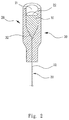
- Figure 1 shows the perspective view of the assembly of a lightguide and a light source coupling seat of the lightguide assembly of the present invention and Figure 2 shows its cross-sectional view. Figure 1 also shows the associative relationship between the assembly of the lightguide and the light source coupling seat, and the main body 10.
- the light source coupling seat 20 serves to interface the lightguide 30 and a light source (not shown).
- the lightguide 30 may be an optical fiber
- the light source may be a laser source, for example, an optical fiber cable or a laser head.
- the lightguide 30 may be any light conductive material. Suitable materials for the lightguide 30 include: glass, plastic, metal oxides and the like.
- a protective film may be provided on the surface of the lightguide 30 by, for example, coating. There is no particularly limitation in the material of the protective film.
- the cross-sectional shape of the lightguide 30 may be elliptical, but may also be circular, square, or polygonal or in a figure-8 configuration. If necessary, the lightguide 30 can also be a beam of two or more optical fibers twisted together. In the following description, the lightguide will be described, taking the optical fiber as an example.
- the long axis of the cross section of the lightguide 30 reduces from its light source section (first section) 31 to its main body section (second section) 33.
- the long axis is the diameter of the optical fiber. Reduction of the long axis may be a continuous reduction or a gradient reduction.
- the lightguide 30 will include along its length direction: a first portion 31 at the end portion of the first section, a narrowing section 32 connected to the first portion 31, and a second portion 33 connected to the narrowing section 32, and to extend to the second section.
- the first portion 31 is aligned with a junction plane prepared in the light source coupling seat 20, to be coupled to the light source.
- the second section 33 is to be disposed within the lightguide groove 11 of the main body 10 and to extend to the distal end 12 of the main body 10.
- the long axis, or diameter, of the lightguide 30 starts to reduce from the junction of the first portion 31 and the narrowing section 32 and the reduction ends at the junction of the narrowing section 32 and the second portion 33.
- the long axis or diameter of the first portion 31 may be between 200um to 1000um, preferably between 450um to 500um.
- the exact size of the first portion 31 is not any technical limitation and is preferably compatible with the size of a light emitting surface of the light source.
- the long axis or diameter of the second portion 33 may be between 30um to 100um, preferably between 40um to 50um.
- the exact size of the second portion 33 is not any technical limitation and is preferably in accordance with the actual needs.
- the long axis or diameter of the second portion 33 may be 40-50um, so that the lightguide 30 may be easily disposed in the side wall of the main body 10.
- the second portion 33 preferably extends to the distal end 12 of the main body 10, while it may retract within the distal end or extend beyond the distal end.
- the light guide may be a side light optical fiber or tail light optical fiber, depending on the purpose of application.
- Method for forming the narrowing section 32 of the lightguide 30 is not limited but is preferably a technique to produce a gradual or progressive reduction in the long axis of an elongated lightguide, such as an optical fiber. Suitable methods include heating stretch at high temperature, molding and other methods. Among them, stretching at high temperature produces an optical fiber with continuously reduced long axis is preferred, because the product is advantageous in transmission of light beams. Molding method forms a lightguide with gradient reduction in long axis, the advantage of which is accuracy in size of each section. Length of the narrowing section 32 is not particularly limited, but is preferably as short as possible.
- length of the narrowing section 32 can be 1mm to 5mm, so that the reduction ratio is 1/10 to 1/2 per mm. This ratio can reduce the length of the narrowing section 32, while efficient transmission of optical power is obtained.
- Other reduction ratios can also be used in the present invention, to obtain the same or similar effects.
- the reduction ratio is not necessarily linear.
- the light source coupling seat 20 may be made from a rigid or flexible material. Suitable materials include plastic, silicone, resin and other plastic material. It is also possible to use metal, ceramic and other materials that are easy to process, to prepare the light source coupling seat 20.
- the top surface of the light source coupling seat 20 forms a plane. This, however, is not any technical limitation.
- the top surface of the coupling seat 20 may be convex, concave or in another shape. The top surface may form a particular pattern or design, by using any applicable technique. It is also possible to form level difference, guide grooves or chamfer at the top surface of the coupling seat 20.
- the light source coupling seat 20 provides a recess 21, which is open to the top surface of the coupling seat 20, whereby a cavity to accommodate a light source is formed.
- the bottom of the recess forms a junction plane 22.
- Shape of the opening of the recess 21 preferably complements a contour of the corresponding portion of a light source (not shown), so that the light source can be securely received within the recess 21.
- the light source is an optical cable with a diameter of about 500um
- the recess 21 may provide an inner diameter of about 500um, to be plugged by the optical cable.
- the light source is a laser head
- the laser head may provide a protrude with a diameter of about 500um.
- the recess 21 also provides an inner diameter of about 500um for coupling of the laser head.
- the junction plane is preferably a plane. If no recess is provided in the light source coupling seat 20, the junction plane 22 may be provided at a top surface of the coupling seat 20.
- a conventional mating sleeve or an adaptor or interconnector may also be used to strengthen the connection of the light source coupling seat 20 and the laser head, in place of or in addition to the recess and/or extrusion.
- junction plane provided in the light source coupling seat 20 is not necessarily a physical plane at the surface of an object.
- the junction plane may be an imaginary plane.
- the junction plane may also be a top surface of the first section 31 of the lightguide 30.
- the embodiment may provide a light source with a recess, such as a laser head socket.
- the lightguide 30 is connectable with the light source coupling seat 20 in a variety of ways.
- the lightguide 30 is connected with the light source coupling seat 20 by injection molding.
- a tool is used to affix the assembly of the lightguide 30 and the light source coupling seat 20 as described above and the lightguide 30 is disposed in a mold that provides a cavity having a contour complimentary to the coupling seat 20.
- Materials for the coupling seat 20 is provided to the cavity to form the coupling seat 20.
- the assembly is removed from the mold, followed by necessary annealing. An assembly of a lightguide and a light source coupling seat is formed.
- the first portion 31 of the lightguide 30 is aligned with the junction plane of the light source coupling seat 20. If the coupling seat 20 has a recess 21, the first portion 31 of the lightguide 30 is aligned with the recess 21 of the coupling seat 20, such that an end surface of the first portion 31 is aligned with the light emitting surface of the light source to be accommodated in the recess 21 of the coupling seat 20.
- the main body 10 may be made from any material but is preferably by a flexible material. Suitable materials include metal, ceramic, plastics, glass, or carbon fiber.
- the lightguide groove 11 may be formed in advance in the body 10, the inner diameter of the lightguide groove 11 of the main body 10 shall be sufficient to accommodate a portion of the lightguide 30.
- the inner diameter of the lightguide groove 11 is preferably greater than the diameter of the lightguide 30 to embed the lightguide 30 in the lightguide groove 11, but it is acceptable if the lightguide 30 protrude from the side of the main body 10.
- Suitable main body 10 of the present invention include a flexible tube, such as those used in industrial, medical applications, service industry and household.
- the distal end 12 of the main body 10 may have a diagonal cut, to facilitate puncture function of the main body 10.
- the shape of the cut is not limited but is preferably a shape easy to produce.
- the lightguide groove 11 is provided in the wall of the tube, extended along the longitudinal direction of the main body 10.
- the main body may be used to transport other fluid or to accommodate a medium for electricity or signal transmission.
- Method for forming the lightguide groove 11 is not limited. Any known art may be used to prepare the lightguide groove. Applicable methods include casting, etching, laser cutting, forging, heat extension etc., as long as an open groove extended along the longitudinal direction of the main body 10, sufficient to accommodate a part of the lightguide 30 is formed in the main body 10.
- the step of forming the lightguide groove 11 is not necessary; the assembly of the lightguide and the light source coupling seat is coupled to the main body 10 in the formation of the main body
- the assembly of the lightguide 30 and the light source coupling seat 20 is disposed in a mold that provides a cavity having a contour complimentary to the main body 10.
- a plurality of lightguide-light source coupling seat assemblies, or an assembly of a plurality of lightguides and a single light source coupling seat, can be disposed within the cavity of the mold.
- Materials for the main body 10 is then provided to the cavity to form the main body 10.
- the assembly is removed from the mold, followed by necessary annealing.
- a lightguide assembly is formed. In the lightguide assembly so prepared.
- the lightguide assembly so produced includes the main body 10, at least one lightguide 30 disposed on the wall or the side wall of the main body 10, and at least one light source coupling seat connecting to each lightguide 10.
- the first portion 31 of each lightguide 30 is aligned with the junction plane of the respective light source coupling seats 20. If the coupling seat 20 has a recess 21, the first portion 31 of the lightguide 30 is aligned with the recess 21 of the coupling seat 20, such that an end surface of the first portion 31 is aligned with the light emitting surface of the light source to be accommodated in the recess 21 of the coupling seat 20.
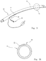
- Figure 3 is a perspective view of one embodiment of the lightguide assembly of the present invention.
- Figure 3A is the cross-sectional view of its main body.
- the figures show an application example of the invented lightguide assembly in medical catheters.
- the main body 10 has a tube-shape and can be an endotrachea tube.
- the main body 10 can also be a nasogastric tube, etc.
- An assembly of the lightguide 30 and the light source coupling seat 20 is provided on the main body 10.
- the first section 11 of the main body 10 adjacent to the light source coupling seat 20 may include at least one fluid access.
- the first section 11 may further include a coupler for coupling a plurality of fluid catheters, optical conductor and/or signal conductor.
- the proximal end of the tube further includes a bubble 13 for compressing air into the distal end 12 of the tube 10 emoting from the light source coupling seat 20.
- the distal end 12 may also include at least one fluid access.
- the distal end 12 of the tube may have a diagonal cut to facilitate puncture purposes of the tube.
- optical powers can be introduced to the distal end 12 of the tube 10, to irradiate human tissues at the distal end 12 or the surroundings along the tube 10.
- Figure 3A shows the coupling of the main body 10 and a lightguide 30, but as is well known, the wall of the tube 10 may be disposed with more than one lightguide 30.
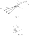
- Figure 4 is a perspective view of another embodiment of the lightguide assembly of the present invention.
- Figure 4A is the cross-sectional view of its main body.
- the figures show another application example of the invented lightguide assembly as a medical catheter.
- the main body 10 is a tube and can be a central venous catheter, peripherally inserted central catheter, hemodialysis catheter, etc.
- An assembly of the lightguide 30 and the light source coupling seat 20 is provided on the main body 10.
- the proximal end 14 of the main body 10 adjacent to the light source coupling seat 20 may include at least one catheter coupler 15 for coupling a plurality of fluid catheters, optical conductors and/or signal conductors.
- the assembly of the lightguide 30 and the light source coupling seat 20 is inserted in one of the cavities.
- the distal end 12 of the tube 10 remoting from the light source coupling seat 20 may include at least one other fluid access.
- the second section of the tube may have a diagonal cut to facilitate puncture purposes of the tube.
- optical powers can be introduced to the distal end 12 of the tube 10, to irradiate body fluids at the distal end 12 or the surroundings of the tube 10, such as human blood.
- Figure 4A shows the assembly of the main body 10 and the lightguide 30.
- the interior of the tube 10 is divided into three channels, wherein the lightguide 30 only occupies one channel.
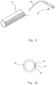
- Figure 5 is a perspective view of the third embodiment of the lightguide assembly of the present invention.
- Figure 5A is the cross-sectional view of its main body.
- the figures show the application example of the invented lightguide assembly used as other medical catheters.
- the main body 10 is a tube and can be a surgical drain, chest tube, urinary catheter, etc.
- a plurality of lightguides 30 is provided in the main body 10, with each lightguide 30 connected to a corresponding light source coupling seat 20. Of course, it is also allowed to connect all the lightguide to a single light source coupling seat.
- optical powers can be introduced to the distal end 12 of the tube 10, to irradiate human tissues or body fluids at the distal end 12 or the surroundings of the tube 10.
- Figure 5A shows the assembly of the main body 10 and a plurality of lightguides 30.
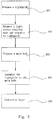
- Figure 6 shows the flowchart of the method for preparation of a lightguide assembly in accordance with one embodiment of the present invention.
- a lightguide 30 is prepared.
- An end of the lightguide 30 has a first portion 31, a narrowing section 32 connected to the first portion 31, and a second portion 33 connected to narrowing section 32 and extend to the second section 33 on the other end of the lightguide.
- the long axis of the cross section of the lightguide 30 reduces from a first portion end of the narrowing section to a second portion end of the narrowing section.
- the long axis may be the diameter of the lightguide.
- the reduction may be a gradual reduction or a gradient reduction.
- a light source coupling seat 20 with a light source junction plan 22 is prepared.
- the first portion 31 and the narrowing section 32 of the lightguide 30 is positioned in the light source coupling seat 20.
- a main body 10 is prepared. At least one lightguide groove 11 is provided in a side wall of the main body 10, with the second portion 33 of the lightguide 30 disposed in the lightguide groove 11.
- the lightguide 30 is assembled to the main body 10.
- the preparation of the main body 10 and the connection of the lightguide 30 to the main body 10 are completed in a single step, such as a injection molding step, to form the main body 10 and the lightguide 30 can be integrally, thus omitting the step of producing the lightguide groove 11.
- step 605 a protection layer is coated on the surface of the main body 10 to cover both the main body 10 and the lightguide groove 11 and to fill any clearance between the lightguide 30 and the lightguide groove 11. Preparation of the invented lightguide assembly is thus completed. However, if the main body 10 and the lightguide 30 are integrally formed, step 605 can be omitted.
- the junction plane is provided in a recess and an end surface of the first portion of the lightguide is aligned with the recess after formation of the light source coupling seat.
- the step of forming a light source coupling seat may further include the formation of a recess in the light source coupling seat.
- the light source coupling seat 20 does not provide a recess 21 but, instead, a light source junction plane at the top surface of the coupling seat 20, in such an embodiment, since a narrowing section 32 that is useful in coupling the optical fiber 30 to an optical fiber cable has been provided, simply irradiating the junction plane with a commercially available laser source, such as a laser pointer, would cause the transmission of light power to the second section 33 of the lightguide 30.
- the recess 21 may be formed at step 604, or in a later step by, such as, milling or lasering process. In such a step, the junction plane may also be processed to form required optical shape or characters.
- the light source coupling seat 20 is preferably formed by molding, such as injection molding.
- certain positioning tools may be used. The tools will become part of the main body 10 or coupling seat 20 after formation of the main body 10 and the coupling seat 20.
- the present invention provides a new structure for the lightguide assembly.
- the lightguide assembly can be prepared easily.
- the lightguide assembly provides a lightguide groove and is easy to produce and assemble.
- the lightguide used in this invention is connectable with a variety type of light sources, without the need of an additional coupler.
- the present invention provides a lightguide assembly that is easy to produce and can be effectively utilized in existing catheters, cannulas, etc., to provide light illumination applications.
Landscapes
- Health & Medical Sciences (AREA)
- Life Sciences & Earth Sciences (AREA)
- Physics & Mathematics (AREA)
- Surgery (AREA)
- Optics & Photonics (AREA)
- Engineering & Computer Science (AREA)
- Biomedical Technology (AREA)
- Public Health (AREA)
- Animal Behavior & Ethology (AREA)
- General Health & Medical Sciences (AREA)
- Veterinary Medicine (AREA)
- Heart & Thoracic Surgery (AREA)
- Nuclear Medicine, Radiotherapy & Molecular Imaging (AREA)
- Pathology (AREA)
- Biophysics (AREA)
- Molecular Biology (AREA)
- Medical Informatics (AREA)
- Radiology & Medical Imaging (AREA)
- General Physics & Mathematics (AREA)
- Astronomy & Astrophysics (AREA)
- Anesthesiology (AREA)
- Pulmonology (AREA)
- Hematology (AREA)
- Oral & Maxillofacial Surgery (AREA)
- Optical Couplings Of Light Guides (AREA)
- Light Guides In General And Applications Therefor (AREA)
- Instruments For Viewing The Inside Of Hollow Bodies (AREA)
- Optical Fibers, Optical Fiber Cores, And Optical Fiber Bundles (AREA)
- Media Introduction/Drainage Providing Device (AREA)
Applications Claiming Priority (1)
| Application Number | Priority Date | Filing Date | Title |
|---|---|---|---|
| TW104131668A TW201713060A (zh) | 2015-09-24 | 2015-09-24 | 光導組件 |
Publications (1)
| Publication Number | Publication Date |
|---|---|
| EP3146887A1 true EP3146887A1 (fr) | 2017-03-29 |
Family
ID=55696866
Family Applications (1)
| Application Number | Title | Priority Date | Filing Date |
|---|---|---|---|
| EP16158687.0A Withdrawn EP3146887A1 (fr) | 2015-09-24 | 2016-03-04 | Ensemble de guide de lumière |
Country Status (5)
| Country | Link |
|---|---|
| US (1) | US20170090179A1 (fr) |
| EP (1) | EP3146887A1 (fr) |
| JP (1) | JP2017062457A (fr) |
| CN (1) | CN106556889A (fr) |
| TW (1) | TW201713060A (fr) |
Cited By (1)
| Publication number | Priority date | Publication date | Assignee | Title |
|---|---|---|---|---|
| WO2018236812A1 (fr) | 2017-06-21 | 2018-12-27 | Inikoa Medical, Inc. | Appareil et procédés de désinfection |
Families Citing this family (4)
| Publication number | Priority date | Publication date | Assignee | Title |
|---|---|---|---|---|
| US10036867B2 (en) | 2016-08-31 | 2018-07-31 | International Business Machines Corporation | Illuminating cable for enhanced traceability |
| TWI642425B (zh) * | 2017-12-01 | 2018-12-01 | I-Shou University | 可控式雷射針灸儀 |
| US10551544B2 (en) * | 2018-01-21 | 2020-02-04 | Lumus Ltd. | Light-guide optical element with multiple-axis internal aperture expansion |
| CN113041159A (zh) * | 2021-03-23 | 2021-06-29 | 昆明医科大学第二附属医院 | 一种便于置入幽门的新型胃管 |
Citations (14)
| Publication number | Priority date | Publication date | Assignee | Title |
|---|---|---|---|---|
| US4826280A (en) * | 1983-06-09 | 1989-05-02 | Sumitomo Electric Industries, Ltd. | Grooved optical transmission channel |
| US4870952A (en) * | 1983-10-28 | 1989-10-03 | Miquel Martinez | Fiber optic illuminator for use in surgery |
| US5888194A (en) * | 1995-12-14 | 1999-03-30 | Mitsubishi Cable Industries, Inc. | Endoscope including an improved lighting apparatus |
| US20090185392A1 (en) * | 2003-03-26 | 2009-07-23 | Optim, Inc. | Detachable illumination system |
| US20110071349A1 (en) * | 2009-09-23 | 2011-03-24 | Entellus Medical, Inc. | Endoscope system for treatment of sinusitis |
| US20120245420A1 (en) * | 2011-03-25 | 2012-09-27 | Koji Yoshida | Endoscope apparatus |
| US20140121538A1 (en) | 2011-06-28 | 2014-05-01 | Koninklijke Philips N.V. | Needle with an optical fiber integrated in an elongated insert |
| CN103901233A (zh) | 2014-04-11 | 2014-07-02 | 华中科技大学 | 具有保偏特性的光纤探针及其制备方法 |
| US20140243806A1 (en) | 2010-02-21 | 2014-08-28 | Pattanam Srinivasan | Fiber Embedded Hollow Needle For Percutaneous Delivery Of Laser Energy |
| WO2014133500A1 (fr) | 2013-02-27 | 2014-09-04 | Empire Technology Development Llc | Sonde à aiguille diagnostique |
| CN204073134U (zh) | 2014-07-22 | 2015-01-07 | 平湖邑飞光电科技有限公司 | 智能多通道复合半导体激光治疗仪 |
| TWM493360U (zh) | 2014-09-03 | 2015-01-11 | Classconn Biotech Co Ltd | 應用於靜脈雷射之光纖針頭 |
| CN104287960A (zh) | 2014-10-13 | 2015-01-21 | 上海大学 | 光纤针灸针 |
| US20150223671A1 (en) * | 2012-09-03 | 2015-08-13 | Meta Biomed Co., Ltd. | Catheter using optical fiber and camera |
Family Cites Families (3)
| Publication number | Priority date | Publication date | Assignee | Title |
|---|---|---|---|---|
| AU2005228956B2 (en) * | 2004-03-23 | 2011-08-18 | Boston Scientific Limited | In-vivo visualization system |
| ES2716808T3 (es) * | 2010-11-17 | 2019-06-17 | Dornier Medtech Laser Gmbh | Unidad de guía de luz para un aplicador láser |
| US9427138B2 (en) * | 2011-09-20 | 2016-08-30 | Boston Scientific Scimed, Inc. | Access devices and related methods of use |
-
2015
- 2015-09-24 TW TW104131668A patent/TW201713060A/zh unknown
-
2016
- 2016-01-29 US US15/011,222 patent/US20170090179A1/en not_active Abandoned
- 2016-03-04 EP EP16158687.0A patent/EP3146887A1/fr not_active Withdrawn
- 2016-03-16 CN CN201610149443.6A patent/CN106556889A/zh not_active Withdrawn
- 2016-05-03 JP JP2016092854A patent/JP2017062457A/ja active Pending
Patent Citations (14)
| Publication number | Priority date | Publication date | Assignee | Title |
|---|---|---|---|---|
| US4826280A (en) * | 1983-06-09 | 1989-05-02 | Sumitomo Electric Industries, Ltd. | Grooved optical transmission channel |
| US4870952A (en) * | 1983-10-28 | 1989-10-03 | Miquel Martinez | Fiber optic illuminator for use in surgery |
| US5888194A (en) * | 1995-12-14 | 1999-03-30 | Mitsubishi Cable Industries, Inc. | Endoscope including an improved lighting apparatus |
| US20090185392A1 (en) * | 2003-03-26 | 2009-07-23 | Optim, Inc. | Detachable illumination system |
| US20110071349A1 (en) * | 2009-09-23 | 2011-03-24 | Entellus Medical, Inc. | Endoscope system for treatment of sinusitis |
| US20140243806A1 (en) | 2010-02-21 | 2014-08-28 | Pattanam Srinivasan | Fiber Embedded Hollow Needle For Percutaneous Delivery Of Laser Energy |
| US20120245420A1 (en) * | 2011-03-25 | 2012-09-27 | Koji Yoshida | Endoscope apparatus |
| US20140121538A1 (en) | 2011-06-28 | 2014-05-01 | Koninklijke Philips N.V. | Needle with an optical fiber integrated in an elongated insert |
| US20150223671A1 (en) * | 2012-09-03 | 2015-08-13 | Meta Biomed Co., Ltd. | Catheter using optical fiber and camera |
| WO2014133500A1 (fr) | 2013-02-27 | 2014-09-04 | Empire Technology Development Llc | Sonde à aiguille diagnostique |
| CN103901233A (zh) | 2014-04-11 | 2014-07-02 | 华中科技大学 | 具有保偏特性的光纤探针及其制备方法 |
| CN204073134U (zh) | 2014-07-22 | 2015-01-07 | 平湖邑飞光电科技有限公司 | 智能多通道复合半导体激光治疗仪 |
| TWM493360U (zh) | 2014-09-03 | 2015-01-11 | Classconn Biotech Co Ltd | 應用於靜脈雷射之光纖針頭 |
| CN104287960A (zh) | 2014-10-13 | 2015-01-21 | 上海大学 | 光纤针灸针 |
Cited By (2)
| Publication number | Priority date | Publication date | Assignee | Title |
|---|---|---|---|---|
| WO2018236812A1 (fr) | 2017-06-21 | 2018-12-27 | Inikoa Medical, Inc. | Appareil et procédés de désinfection |
| EP3641836A4 (fr) * | 2017-06-21 | 2020-07-08 | Inikoa Medical, Inc. | Appareil et procédés de désinfection |
Also Published As
| Publication number | Publication date |
|---|---|
| US20170090179A1 (en) | 2017-03-30 |
| CN106556889A (zh) | 2017-04-05 |
| JP2017062457A (ja) | 2017-03-30 |
| TW201713060A (zh) | 2017-04-01 |
Similar Documents
| Publication | Publication Date | Title |
|---|---|---|
| US10226398B2 (en) | Optical needle with lightguide groove | |
| US20170090179A1 (en) | Lightguide Assembly | |
| EP3685734B1 (fr) | Dispositif médical comprenant un guide d'ondes à gaine | |
| US10420540B2 (en) | Illuminated surgical retractor | |
| US9519107B2 (en) | Methods and apparatus related to a launch connector portion of a ureteroscope laser-energy-delivery device | |
| US5154708A (en) | Unitary scalpel for contact laser surgery | |
| USRE46362E1 (en) | Twin sealing chamber hub | |
| US20170080181A1 (en) | Catheter, catheter production mold, catheter production method | |
| WO2024000926A1 (fr) | Endoscope flexible et robot endoscopique flexible | |
| CN219270851U (zh) | 前端头组件和内窥镜 | |
| US20120238830A1 (en) | Hybrid Fiber-Optic Cannula | |
| CN114587577A (zh) | 用于激光消融的装置 | |
| JPWO2016194455A1 (ja) | 内視鏡用コネクタ | |
| KR20080079530A (ko) | 치과용 석션팁 | |
| JP3689320B2 (ja) | 処置具起上装置を有する内視鏡 | |
| EP3146997B1 (fr) | Aiguille optique | |
| CN109568772B (zh) | 一种变径中心静脉导管及其制备方法 | |
| CN115300099A (zh) | 激光消融冷却器及其制造方法 | |
| KR20140137975A (ko) | 비강용 수술도구 및 이를 이용한 수술도구 어셈블리 | |
| CN115253041B (zh) | 一种多腔引流管皮下潜行装置 | |
| CN217118530U (zh) | 外科用穿刺引流组件和外科用穿刺引流系统 | |
| CN121621916A (zh) | 一种导管及内窥镜 | |
| CN117462792A (zh) | 水光针 | |
| CN116407329A (zh) | 鞘芯组件、鞘芯组件的制作方法及输送器 | |
| CN105582594A (zh) | 一种防针刺穿刺式连接件专用输液针 |
Legal Events
| Date | Code | Title | Description |
|---|---|---|---|
| PUAI | Public reference made under article 153(3) epc to a published international application that has entered the european phase |
Free format text: ORIGINAL CODE: 0009012 |
|
| STAA | Information on the status of an ep patent application or granted ep patent |
Free format text: STATUS: THE APPLICATION HAS BEEN PUBLISHED |
|
| AK | Designated contracting states |
Kind code of ref document: A1 Designated state(s): AL AT BE BG CH CY CZ DE DK EE ES FI FR GB GR HR HU IE IS IT LI LT LU LV MC MK MT NL NO PL PT RO RS SE SI SK SM TR |
|
| AX | Request for extension of the european patent |
Extension state: BA ME |
|
| STAA | Information on the status of an ep patent application or granted ep patent |
Free format text: STATUS: THE APPLICATION IS DEEMED TO BE WITHDRAWN |
|
| 18D | Application deemed to be withdrawn |
Effective date: 20170930 |