EP3146997B1 - Aiguille optique - Google Patents
Aiguille optique Download PDFInfo
- Publication number
- EP3146997B1 EP3146997B1 EP16158669.8A EP16158669A EP3146997B1 EP 3146997 B1 EP3146997 B1 EP 3146997B1 EP 16158669 A EP16158669 A EP 16158669A EP 3146997 B1 EP3146997 B1 EP 3146997B1
- Authority
- EP
- European Patent Office
- Prior art keywords
- light source
- lightguide
- needle
- section
- coupling seat
- Prior art date
- Legal status (The legal status is an assumption and is not a legal conclusion. Google has not performed a legal analysis and makes no representation as to the accuracy of the status listed.)
- Not-in-force
Links
- 230000003287 optical effect Effects 0.000 claims description 72
- 230000008878 coupling Effects 0.000 claims description 71
- 238000010168 coupling process Methods 0.000 claims description 71
- 238000005859 coupling reaction Methods 0.000 claims description 71
- 239000013307 optical fiber Substances 0.000 claims description 48
- 230000009467 reduction Effects 0.000 claims description 21
- 238000000034 method Methods 0.000 claims description 20
- 239000000463 material Substances 0.000 claims description 13
- 238000002360 preparation method Methods 0.000 claims description 9
- 239000004033 plastic Substances 0.000 claims description 6
- 229920003023 plastic Polymers 0.000 claims description 6
- 230000004308 accommodation Effects 0.000 description 6
- 238000001467 acupuncture Methods 0.000 description 6
- 230000005540 biological transmission Effects 0.000 description 6
- 238000010586 diagram Methods 0.000 description 4
- 238000003780 insertion Methods 0.000 description 4
- 230000037431 insertion Effects 0.000 description 4
- 239000002184 metal Substances 0.000 description 4
- 239000000523 sample Substances 0.000 description 4
- 238000001514 detection method Methods 0.000 description 3
- 238000000465 moulding Methods 0.000 description 3
- 230000000750 progressive effect Effects 0.000 description 3
- 230000008901 benefit Effects 0.000 description 2
- 239000011248 coating agent Substances 0.000 description 2
- 238000000576 coating method Methods 0.000 description 2
- 230000000295 complement effect Effects 0.000 description 2
- 238000013532 laser treatment Methods 0.000 description 2
- 239000011148 porous material Substances 0.000 description 2
- 230000008569 process Effects 0.000 description 2
- 230000001681 protective effect Effects 0.000 description 2
- 229920000049 Carbon (fiber) Polymers 0.000 description 1
- 238000000137 annealing Methods 0.000 description 1
- 230000015572 biosynthetic process Effects 0.000 description 1
- 239000004917 carbon fiber Substances 0.000 description 1
- 239000000919 ceramic Substances 0.000 description 1
- 238000006073 displacement reaction Methods 0.000 description 1
- 230000000694 effects Effects 0.000 description 1
- 230000005611 electricity Effects 0.000 description 1
- 239000011521 glass Substances 0.000 description 1
- 239000003365 glass fiber Substances 0.000 description 1
- 238000010438 heat treatment Methods 0.000 description 1
- 238000001746 injection moulding Methods 0.000 description 1
- 230000010354 integration Effects 0.000 description 1
- 238000001990 intravenous administration Methods 0.000 description 1
- 230000001678 irradiating effect Effects 0.000 description 1
- 238000004519 manufacturing process Methods 0.000 description 1
- 229910044991 metal oxide Inorganic materials 0.000 description 1
- 150000004706 metal oxides Chemical class 0.000 description 1
- VNWKTOKETHGBQD-UHFFFAOYSA-N methane Chemical compound C VNWKTOKETHGBQD-UHFFFAOYSA-N 0.000 description 1
- 229920001296 polysiloxane Polymers 0.000 description 1
- 230000011514 reflex Effects 0.000 description 1
- 229920005989 resin Polymers 0.000 description 1
- 239000011347 resin Substances 0.000 description 1
- 230000000638 stimulation Effects 0.000 description 1
- 238000011282 treatment Methods 0.000 description 1
Images


Classifications
-
- A—HUMAN NECESSITIES
- A61—MEDICAL OR VETERINARY SCIENCE; HYGIENE
- A61N—ELECTROTHERAPY; MAGNETOTHERAPY; RADIATION THERAPY; ULTRASOUND THERAPY
- A61N5/00—Radiation therapy
- A61N5/06—Radiation therapy using light
- A61N5/0613—Apparatus adapted for a specific treatment
- A61N5/0619—Acupuncture
-
- A—HUMAN NECESSITIES
- A61—MEDICAL OR VETERINARY SCIENCE; HYGIENE
- A61H—PHYSICAL THERAPY APPARATUS, e.g. DEVICES FOR LOCATING OR STIMULATING REFLEX POINTS IN THE BODY; ARTIFICIAL RESPIRATION; MASSAGE; BATHING DEVICES FOR SPECIAL THERAPEUTIC OR HYGIENIC PURPOSES OR SPECIFIC PARTS OF THE BODY
- A61H39/00—Devices for locating or stimulating specific reflex points of the body for physical therapy, e.g. acupuncture
- A61H39/08—Devices for applying needles to such points, i.e. for acupuncture ; Acupuncture needles or accessories therefor
- A61H39/086—Acupuncture needles
-
- A—HUMAN NECESSITIES
- A61—MEDICAL OR VETERINARY SCIENCE; HYGIENE
- A61B—DIAGNOSIS; SURGERY; IDENTIFICATION
- A61B17/00—Surgical instruments, devices or methods
- A61B17/34—Trocars; Puncturing needles
-
- A—HUMAN NECESSITIES
- A61—MEDICAL OR VETERINARY SCIENCE; HYGIENE
- A61B—DIAGNOSIS; SURGERY; IDENTIFICATION
- A61B17/00—Surgical instruments, devices or methods
- A61B17/34—Trocars; Puncturing needles
- A61B17/3417—Details of tips or shafts, e.g. grooves, expandable, bendable; Multiple coaxial sliding cannulas, e.g. for dilating
- A61B17/3421—Cannulas
-
- G—PHYSICS
- G02—OPTICS
- G02B—OPTICAL ELEMENTS, SYSTEMS OR APPARATUS
- G02B6/00—Light guides; Structural details of arrangements comprising light guides and other optical elements, e.g. couplings
- G02B6/02—Optical fibres with cladding with or without a coating
-
- A—HUMAN NECESSITIES
- A61—MEDICAL OR VETERINARY SCIENCE; HYGIENE
- A61B—DIAGNOSIS; SURGERY; IDENTIFICATION
- A61B17/00—Surgical instruments, devices or methods
- A61B2017/00526—Methods of manufacturing
-
- A—HUMAN NECESSITIES
- A61—MEDICAL OR VETERINARY SCIENCE; HYGIENE
- A61H—PHYSICAL THERAPY APPARATUS, e.g. DEVICES FOR LOCATING OR STIMULATING REFLEX POINTS IN THE BODY; ARTIFICIAL RESPIRATION; MASSAGE; BATHING DEVICES FOR SPECIAL THERAPEUTIC OR HYGIENIC PURPOSES OR SPECIFIC PARTS OF THE BODY
- A61H39/00—Devices for locating or stimulating specific reflex points of the body for physical therapy, e.g. acupuncture
- A61H2039/005—Devices for locating or stimulating specific reflex points of the body for physical therapy, e.g. acupuncture by means of electromagnetic waves, e.g. I.R., U.V. rays
-
- A—HUMAN NECESSITIES
- A61—MEDICAL OR VETERINARY SCIENCE; HYGIENE
- A61H—PHYSICAL THERAPY APPARATUS, e.g. DEVICES FOR LOCATING OR STIMULATING REFLEX POINTS IN THE BODY; ARTIFICIAL RESPIRATION; MASSAGE; BATHING DEVICES FOR SPECIAL THERAPEUTIC OR HYGIENIC PURPOSES OR SPECIFIC PARTS OF THE BODY
- A61H2201/00—Characteristics of apparatus not provided for in the preceding codes
- A61H2201/01—Constructive details
- A61H2201/0188—Illumination related features
-
- A—HUMAN NECESSITIES
- A61—MEDICAL OR VETERINARY SCIENCE; HYGIENE
- A61H—PHYSICAL THERAPY APPARATUS, e.g. DEVICES FOR LOCATING OR STIMULATING REFLEX POINTS IN THE BODY; ARTIFICIAL RESPIRATION; MASSAGE; BATHING DEVICES FOR SPECIAL THERAPEUTIC OR HYGIENIC PURPOSES OR SPECIFIC PARTS OF THE BODY
- A61H2201/00—Characteristics of apparatus not provided for in the preceding codes
- A61H2201/10—Characteristics of apparatus not provided for in the preceding codes with further special therapeutic means, e.g. electrotherapy, magneto therapy or radiation therapy, chromo therapy, infrared or ultraviolet therapy
-
- A—HUMAN NECESSITIES
- A61—MEDICAL OR VETERINARY SCIENCE; HYGIENE
- A61N—ELECTROTHERAPY; MAGNETOTHERAPY; RADIATION THERAPY; ULTRASOUND THERAPY
- A61N5/00—Radiation therapy
- A61N5/06—Radiation therapy using light
- A61N5/0601—Apparatus for use inside the body
- A61N2005/0612—Apparatus for use inside the body using probes penetrating tissue; interstitial probes
-
- A—HUMAN NECESSITIES
- A61—MEDICAL OR VETERINARY SCIENCE; HYGIENE
- A61N—ELECTROTHERAPY; MAGNETOTHERAPY; RADIATION THERAPY; ULTRASOUND THERAPY
- A61N5/00—Radiation therapy
- A61N5/06—Radiation therapy using light
- A61N2005/063—Radiation therapy using light comprising light transmitting means, e.g. optical fibres
-
- A—HUMAN NECESSITIES
- A61—MEDICAL OR VETERINARY SCIENCE; HYGIENE
- A61N—ELECTROTHERAPY; MAGNETOTHERAPY; RADIATION THERAPY; ULTRASOUND THERAPY
- A61N5/00—Radiation therapy
- A61N5/06—Radiation therapy using light
- A61N5/067—Radiation therapy using light using laser light
Definitions
- the present invention relates to an optical needle, more particularly to a puncture needle having light-guiding characteristics, in order to transmit a light beam into an object.
- the puncture needle is a tool widely used in industry, services and daily life.
- a puncture needle needs to have a light-guiding function.
- Such applications include industrial detection, medical detection and treatment.
- acupuncture where a puncture needle is inserted into the human body through the skin, to reach the position of an acupoint, and thermal, optical or electrical energy is applied to the acupoint through the puncture needle, in order to stimulate physiological reactions at the acupoint.
- One way to apply the energy is to burn the external portion of the puncture needle, in order to transmit the thermal energy to the acupoint through the puncture needle.
- Another way is to apply an electricity to the needle, in order to transmit the electrical energy to the acupoint through the needle.
- a most recent application of the puncture needle is to apply a light beam, in particular a laser beam, to the acupoint through the puncture needle.
- optical needles to be used in medical or acupuncture applications have been developed.
- optical needles for other applications based on transmission of light beams through a puncture needle such as detections using the light beams so transmitted, have also been developed.
- CN103901233A discloses a probe with an optical fiber. An end of the optical probe is etched to form a tip with an oval end surface. A metal coating is provided around the tip, with the tip exposed from the coating.
- CN104287960A discloses an acupuncture needle with an optical fiber provided inside the acupuncture needle.
- An end of the optical fiber forms a tapered tip at a micro pore of the tip of the acupuncture needle, to guide a laser beam into a target position of the needle.
- Other micro pores are provided for the transmission of electrical and optical signals.
- CN204073134 discloses a multi-channel laser treatment equipment, including eight mutually independent laser treatment channels, each including a laser light source and an optical fiber. Laser light is provided in the form of continuous or pulsed irradiations to irradiate an acupoint.
- TW M493360U discloses an optical needle for intravenous irradiations.
- the optical needle provides a through hole at its base.
- An end of the through hole may be connected by a tube, to be inserted by an optical fiber, such that the optical fiber passes through the through hole.
- a cap is provided to seal the through hole, after the optical fiber is sterilized.
- US 2014/0121538A1 discloses an assembly of an optical fiber and a metal needle, which provides a plurality of optical fiber tunnels therein.
- the tip of the needle forms two tilt angles so that an end of the optical fiber protruding from a second tilt angle, without protruding from the first tilt angle.
- US 2014/0243806A1 discloses a hollow needle with optical fibers embedded therein.
- a plurality of tunnels is provided in the needle, to accommodate the plurality of optical fibers.
- a hub is provided to connect the plurality of optical fibers to a laser source.
- a plurality of lightguides is provided, to guide laser beams from the laser source to the respective optical fibers.
- WO 2014/133500A1 discloses a diagnostic probe.
- the probe includes a needle body provided with a plurality of tunnels to accommodate optical fibers.
- the respective optical fibers terminate at different longitudinal positions of the needle body, to collect diagnostic information of tissues surrounding the terminals.
- optical needles have been designed to provide a light-guiding function. These optical needles, however, used a complicated needle body structure. Most optical needles are connected to a separate light source through an optical fiber. In order to connect the lightguide embedded in the optical needle to the optical fiber that is capable of transmitting a light beam for a certain distance, a coupler to align the lightguide and the optical fiber will be necessary. The coupler makes the optical needle system bulky and adds additional costs to the manufacture and application of the system.
- the objective of the present invention is to provide a novel structure for the optical needle to enable the integration of the optical needle and a light source.
- Another objective of the present invention is to provide an optical needle that does not need an optical coupler.
- Another objective of the present invention is to provide an optical needle that is connectable to a light source.
- Another objective of the invention is to provide a novel method for the preparation of an optical needle that is connectable to a light source.
- an optical needle comprises a needle body, a light source coupling seat and a lightguide.
- the needle body provides a cavity to accommodate a portion of the lightguide.
- the light source coupling seat provides a junction plane for interfacing a light source and the lightguide.
- the junction plane may be provided in a recess that can accommodate the light source.
- An end of the needle body is aligned with the junction plane of the light source coupling seat, such that an end of the lightguide is aligned with the junction plane or the light source.
- the other end of the lightguide terminates at the tip of the needle body.
- the optical needle is characterized in that the cross sectional area of the lightguide reduces from a light source section to a needle body section.
- the lightguide is an optical fiber.
- the reduction of the cross sectional area is a continuous reduction or a gradient reduction.
- the light source coupling seat extends in the radial direction of the lightguide, in order to facilitate insertion of the optical needle into an object.
- the optical needle is used to transmit light beams into an object, which may be a human tissue.
- the contact surface of the light source coupling seat with the object may be a substantial plane.
- the junction plane may also be provided on a protruding portion, which may be engaged in a recess provided in a light source coupler.
- the tip of the optical needle may form a diagonal cut to facilitate insertion.
- the top surface of the optical needle may extend to form a plane, to strengthen the combination of the needle body and the light source coupling seat.
- the optical needle of the present invention may further comprise a light source.
- the light source may be an optical fiber cable or a laser head. If the light source is a laser head, the laser head may comprise a laser beam generator for generating a laser beam; a power supply for providing power to the laser beam generator; a coupler to couple the light source to the coupling seat; and a switch for the control of the power supply.
- the laser head may provide a coupling portion with a protrusion having a shape complimentary to the shape of the recess of the light source coupling seat.
- the coupling portion may also have a recess with a shape complimentary to the shape of the protruding portion of the light source coupling seat.
- the protrusion and/or recess of the coupling portion facilitates stable insertion of the laser lead in the light source coupling seat and the alignment of the light emitting surface of the laser lead to the light source end of the lightguide.
- the present invention also discloses a preparation method of optical needle.
- the method comprises: preparing a needle body with a hollow cavity; providing a lightguide with a first section, a narrowing section connected to the first section and a second section connected to the narrowing section.
- the cross sectional area of the lightguide reduces from a junction of the first and narrowing sections to a junction of the narrowing and second sections.
- the method further comprises: placing the second section of the lightguide in the hollow cavity; if necessary, leaving the first and/or narrowing section outside of the hollow cavity; forming a light source coupling seat with a light source junction plane, such that the light source coupling seat encloses a portion of the needle body and the first and narrowing sections of the lightguide and that a first end of the lightguide is aligned with the light source junction plane, to receive light beams entering through the light source junction plane.
- the light source junction plane may be provided in a light source accommodation cavity, such that, when the light source coupling seat is formed, the first end of the lightguide is aligned with the light source accommodation cavity.
- the light source junction plane may also be provided on a protruding portion of the light source coupling seat.
- the present invention provides a novel structure of optical needles and its preparation method.
- the new structure is connectable to a laser source.
- the present invention also provides an optical needle in combination with a laser source.
- the inventor has found that one reason that makes the conventional optical needles complicated in structure is the power consumption of the light source.
- the light source or laser source is made bulky.
- size of lightguide or optical fiber or optical fiber cable used in the optical needle is incompatible with that of the optical fiber used to transmit light beams for a relatively long distance.
- a coupler is needed to connect the lightguide and the optical fiber/cable with high efficiency.
- the inventor also found that the commercially available, small-size laser heads are able to generate laser beams with a wavelength of about 405 nm to 660 nm.
- the laser beams so generated are sufficient to support most applications of the optical needle, where about 1mW or stronger light power is needed.
- the lightguide or optical fiber so obtained would be able to support the coupling of the optical fiber and a light source or a laser source.
- optical needle of the present invention will be described by using its several embodiments. It shall be appreciated that description of the embodiments serves merely to illustrate the basic structure and spirit of the present invention. They shall not be used to limit the scope of protection of this invention.
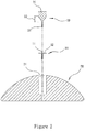
- Figure 1 shows the perspective view of one embodiment of the optical needle of the present invention and Figure 2 shows its cross-sectional view.
- the optical needle of the present invention includes a needle body 10, a light source coupling seat 20 and a lightguide 30.
- the needle body 10 has a cavity 11 for receiving the second portion 33 of the lightguide 30, in this case an optical fiber.
- the needle body 10 may be made from any rigid material. Suitable materials include metal, plastics, glass, or carbon fiber.
- the top surface of the needle body 10 extends in the lateral direction and forms a disc 12. The purpose of the disc shape is to strengthen the combination of the needle body 10 and the coupling seat 20.
- the inner diameter of the cavity 11 of the needle body 10 may be of a fixed value or reduce from its the top to its tip section. At this tip portion, the inner diameter of the cavity 11 may be about 50 to 500um, preferably about 100-250um, and more preferably about 200um.
- the tip of the needle body 10 may have a diagonal cut (not shown) to facilitate puncture purposes of the needle 10.
- the shape of the cut is not limited but is preferably a shape easy to produce.
- the light source coupling seat 20 may be made from a rigid or flexible material. Suitable materials include plastic, silicone, resin and other plastic material. It is also possible to use a metal, ceramic and other materials that are easy to process, to prepare the light source coupling seat 20.
- the top surface of the light source coupling seat 20 forms a spherical shape. This, however, is not any technical limitation.
- the top surface of the coupling seat 20 may be flat, concave or in other shape. The top surface may form a particular pattern or design, by using any applicable technique.
- the coupling seat 20 extends laterally for the convenience of puncturing and inserting the optical needle into an object. This, of course, is not any technical limitation.
- the object may be a human tissue, such as the aforementioned acupoints of the human body.
- the optical needle may serve as an acupuncture needle.
- the lower surface of the light source coupling seat 20 is preferably formed a substantial plane, so that the optical needle forms a relatively large contact surface with the object after insertion, to avoid displacement.
- the lower surface may be formed of other non-planar shape, provided with a pattern, or applied with additional materials.
- the light source coupling seat 20 provides a recess 21 which is open to the top surface of the coupling seat 20, whereby a cavity to accommodate a light source 40 is formed. Shape of the opening of the recess 21 preferably complement a contour of the corresponding portion of the light source 40, so that the light source 40 can be securely received within the recess 21.
- the optical needle provides a light source junction plane 22 in the light source coupling seat 20, at a position inside the recess 21 and above the first end 31 of the lightguide 30.
- the junction plane 22 is preferably flat. If the light source coupling seat 20 does not provide the recess 21, the light source junction plane 22 may be provided on the top surface of the light source coupling seat 20.
- the junction plane 22 and the top surface of the light source coupling seat 20 form substantial flush.
- the light source coupling seat 20 may also provide a protruding portion (not shown), at a portion above the first end 31 of the lightguide 30, so that the protruding portion of the coupling seat 20 may be engaged in a recess (not shown) possibly provided in the light source 40. Contour of this protruding portion preferably complement shape of the recess of the light source.
- junction plane 22 provided in the light source coupling seat 20 is not necessarily a physical plane at the surface of an object.
- the junction plane 22 may be an imaginary plane.
- the junction plane 22 may also be a top surface of the first end 31 of the lightguide 30.
- the lightguide 30 may be any light guiding material and is preferably an optical fiber. Suitable materials for the lightguide 30 include: glass, plastic, metal oxides and the like.
- a protective film may be provided on the surface of the lightguide 30. There is no particularly limitation in the material of the protective film.
- the cross-sectional shape of the lightguide 30 may be elliptical, but may also be circular, square, or polygonal or in a figure-8 configuration. If necessary, the lightguide 30 can also be a beam with two or more optical fibers twisted together.
- the cross sectional area of the lightguide 30 reduces from its light source section (first section) 31 to its needle body end (second section) 33.
- the diameter of the optical fiber reduces.
- Reduction of the cross sectional area may be a continuous reduction or a gradient reduction.
- the lightguide 30 will include along its length direction: a first section 31, a narrowing section 32 connected to the first section 31, and a second section 33 connected to the narrowing section 32.
- the first section 31 is aligned with the recess 21 (Embodiment of FIG. 1 ) of the coupling seat 20, to be coupled to the light source 40.
- the second section 33 is to be disposed within the hollow cavity 11 of the needle body 10, and to extend to the tip portion of the needle body 10.
- Thecross sectional area, or diameter, of the lightguide 30 starts to reduce from the junction of the first section 31 and the narrowing section 32 and the reduction ends at the junction of the narrowing section 32 and the second section 33.
- the diameter of the first section 31 may be between 200um to 1000um, preferably between 450um to 500um.
- the exact size of the first section 31 is not any technical limitation and is preferably compatible with the size of a light emitting surface of the light source 40.
- the diameter of the second section 33 may be between 30um to 100um, preferably between 40um to 50um.
- the exact size of the second section 33 is not any technical limitation and is preferably compatible with the size of an inner diameter of the cavity 11. If the inner diameter of the cavity 11 at the tip portion is 100 um, the diameter of the second section 33 may be 50um, so that the lightguide 30 may be easily disposed in the cavity 11 of the needle body 10.
- the second section 33 preferably terminates at the needle tip, while it may retract within the needle tip or extend beyond the needle tip.
- Method for forming the narrowing section 32 of the lightguide 30 is not limited but is preferably a technique to produce a gradual or progressive reduction in the cross sectional area of an elongated lightguide, such as an optical fiber.
- Suitable methods include heating stretch at high temperature, molding and other methods. Among them, stretching at high temperature produces an optical fiber with continuously reduced cross sectional area; the product is advantageous in transmission of light beams. Molding method forms a lightguide with gradient reduction in cross sectional area, the advantage of which is accuracy in size of each section.
- Length of the narrowing section 32 is not particularly limited, but is preferably as short as possible.
- length of the narrowing section 32 can be 1mm to 5mm, so that the reduction ratio is 1/10 to 1/2 per mm. This ratio can reduce the length of the narrowing section 32, while efficient transmission of optical power is obtained.
- Other reduction ratios can also be used in the present invention, to obtain the same or similar effects.
- the reduction ratio is not necessarily linear.
- the structure of the needle body 10 is preferably designed to accommodate the narrowing section 32 in the cavity, when the optical fiber 30 is disposed within the needle 10. If the cavity 11 has a fixed inner diameter along its length direction, the narrowing section 32 and the first section 31 will be disposed external to the cavity 11, i.e., beyond the top end 12 of the needle body 10. On the other hand, if the inner diameter of the cavity 11 is progressive, i.e., the inner diameter reduces from the top end 12 to the tip direction, the narrowing section 32 or a portion thereof will be disposed in the cavity 11.
- the top end 12 of the needle body 10 is aligned with the recess 21 of the light source coupling seat 20, such that end surface of the first section 31 is aligned with the light emitting surface of the light source 40 to be accommodated in the recess 21 of the coupling seat 20.
- FIG. 3 is the flowchart of the method for preparation of an optical needle in accordance with the present invention.
- a needle body 10 is prepared.
- the needle body 10 has a cavity 11, with a fixed or progressive diameter along its length direction.
- the top end of the needle body 10 may further include a disc 12 extended laterally.
- a lightguide 30, in this case an optical fiber is prepared.
- the optical fiber 30 has a first section 31, a narrowing section 32 connected to the first section 31, and a second section 33 connected to narrowing section 32.
- the cross sectional area of the optical fiber 30 reduces from the junction of the first section 31 and the narrowing section 32 to the junction of the narrowing section 32 and the second section 33.
- the reduction may be a gradual reduction or a gradient reduction.
- the second section 33of the optical fiber 30 is disposed in the cavity 11 of the needle body 10. If the inner diameter of the cavity 11 is fixed, the narrowing section 32 and/or the first section 31 remains outside of the cavity 11.
- a light source coupling seat 20 with a light source accommodation cavity 21 is formed, to encompass a portion of the needle body 100 and the first section 31 and narrowing section 32 of the lightguide 30, while having an end surface of the first section 31 aligned with the light source accommodation cavity 21, in order to receive light beams entering into the light source accommodation cavity 21. Preparation of the invented optical needle is thus completed.
- the light source coupling seat 20 does not provide the light source accommodation cavity 21 but, instead, a light source junction plane 22 at the top surface of the coupling seat 20, or even on a protruding portion of the coupling seat 20.
- a narrowing section 32 that is useful in coupling the optical fiber 30 to an optical fiber cable has been provided, simply irradiating the junction plane 22 with a commercially available laser source, such as a laser pointer, would cause the transmission of light power to the second section 33 of the lightguide 30.
- the light source coupling seat 20 is preferably formed by molding, such as injection molding.
- the products of step 303 are arranged at suited positions in a mold for the light source coupling seat 20 and maintain their relative positions.
- a material for the light source coupling seat 20 is filled in the mold to form the coupling seat 20.
- the optical needle of the present invention is prepared.
- certain positioning tools may be used. The tools will become part of the coupling seat 20 after formation of the coupling seat 20.
- the optical needle of the present invention may further comprise a light source 40.
- the light source 40 may be an optical fiber cable or a laser head. If the light source 40 is an optical fiber cable, an end of the cable will be connected with a light source (not shown), to generate light power needed in the optical needle, whereby the light power may be transmitted to the optical needle through the cable.
- the other end of the optical fiber cable may be inserted in the recess 21 of the coupling seat 20, whereby the narrowing section 32 of the lightguide 30 will couple the light power of the light source to the second section 33 for further use.
- the light source 40 is a laser head.
- Figure 4 shows the exploded view of one example of a laser head 40 applicable in the optical needle of the present invention
- Figure 4A is a schematic diagram of the laser head 40 of Figure 4 , after assembly.
- the laser head 40 includes a laser beam generator 41 for generating a laser beam; a power supply 42 for providing power to the laser beam generator 41; and a switch 43 to control the power supply 42.
- Figure 4 also shows that the laser beam generator 41, the power supply 42 and the switch 43 are assembled in a coupler 44 and integrated to form a laser head 40.
- the coupler 44 provides a coupling end 45, to function as a light emitting surface of the laser head 40.
- the coupler 44 may be inserted in the recess 21 of the light source coupling seat 20, such that the light emitting surface is aligned with end surface of the first section 31 of the lightguide 30.
- the shape and size of the coupling end 45 is preferably compatible with the recess 21, so that the laser head 40 can be inserted and securely placed in the light source coupling seat 20, whereby the light-emitting surface is aligned with end surface of the first section 31 of the lightguide 30.
- any small-scale laser light generator can be used in the present invention.
- the commercially available laser pointer that generates red-color laser beams is applicable in this invention.
- Laser light generated by such laser source has a wavelength of about 405nm to 660nm, which is sufficient to provide about 1mW or higher light power, sufficient for most applications of the optical needle. Since this and other laser sources are well known in the art, details thereof is omitted.
- power supply 42 that supplies electrical power to such a laser source 41 may be any commercially available small-size battery.
- Micro switch 43 to control such power supply 42 is also known.
- the combination of the laser light generator 41, power supply 472 and switch 43 may be determined according to needs in particular applications. Details thereof is also omitted.
- the present invention provides a new structure for the optical needle.
- the optical needle is connectable with a variety type of light sources, without the need of an additional coupler.
- a compact and small-size optical needle that is able to reduce the foot print of the optical needle application system is thus provided.
Landscapes
- Health & Medical Sciences (AREA)
- Life Sciences & Earth Sciences (AREA)
- General Health & Medical Sciences (AREA)
- Veterinary Medicine (AREA)
- Engineering & Computer Science (AREA)
- Biomedical Technology (AREA)
- Animal Behavior & Ethology (AREA)
- Public Health (AREA)
- Rehabilitation Therapy (AREA)
- Nuclear Medicine, Radiotherapy & Molecular Imaging (AREA)
- Pathology (AREA)
- Pain & Pain Management (AREA)
- Surgery (AREA)
- Radiology & Medical Imaging (AREA)
- Physical Education & Sports Medicine (AREA)
- Epidemiology (AREA)
- Physics & Mathematics (AREA)
- Medical Informatics (AREA)
- Molecular Biology (AREA)
- Heart & Thoracic Surgery (AREA)
- Optics & Photonics (AREA)
- General Physics & Mathematics (AREA)
- Optical Couplings Of Light Guides (AREA)
- Finger-Pressure Massage (AREA)
Claims (15)
- Aiguille optique, comprenant un corps d'aiguille (10), un siège de couplage de source de lumière (20) et un guide lumière (30) ; dans laquelle le corps d'aiguille fournit une cavité (11) pour loger une portion du guide lumière (30) ; le siège de couplage de source de lumière (20) fournit un plan de jonction (22) pour servir d'interface entre une source de lumière (40) et le guide lumière (30) ; et une extrémité du corps d'aiguille (10) est alignée avec le plan de jonction (22) du siège de couplage de source de lumière (20), de sorte qu'une extrémité du guide lumière (30) soit alignée avec le plan de jonction (22) ; caractérisée en ce que le guide lumière (30) comprend une première section (31), une section de rétrécissement (32) raccordée à la première section (31) et une seconde section (33) raccordée à la section de rétrécissement (32), et en ce qu'une aire en coupe du guide lumière (30) diminue depuis une jonction de la première section (31) et de la section de rétrécissement (32) jusqu'à une jonction de la section de rétrécissement (32) et de la seconde section (33).
- Aiguille optique selon la revendication 1, dans laquelle le plan de jonction (22) est fourni dans un évidement (21) qui peut loger la source de lumière (40).
- Aiguille optique selon la revendication 1, dans laquelle le plan de jonction (22) est fourni sur une portion saillante, formée au niveau d'une surface haute du siège de couplage de source de lumière (20).
- Aiguille optique selon la revendication 2, comprenant en outre une tête laser (40), ladite tête laser (40) comprenant : un générateur de faisceau laser (41) pour générer un faisceau laser ; une alimentation électrique (42) pour alimenter électriquement le générateur de faisceau laser (41) ; un coupleur (44) pour coupler la source de lumière (40) au siège de couplage (20) ; et un commutateur (43) pour la commande de l'alimentation électrique (42) ; dans laquelle une portion de couplage dotée d'une saillie ayant une forme complémentaire d'une forme de l'évidement (21) du siège de couplage de source de lumière (20) est fournie, de sorte qu'une surface d'émission de lumière de la tête laser (40) soit alignée avec l'extrémité de source de lumière du guide lumière (30).
- Aiguille optique selon l'une quelconque des revendications 1 à 4, dans laquelle le guide lumière (30) comprend une fibre optique.
- Aiguille optique selon l'une quelconque des revendications 1 à 4, dans laquelle une réduction d'aire en coupe du guide lumière (30) est une réduction progressive ou une réduction en gradient.
- Aiguille optique selon la revendication 1, dans laquelle le siège de couplage de source de lumière (20) s'étend dans la direction radiale du guide lumière (30) et une surface inférieure du siège de couplage de source de lumière (20) forme un plan notable.
- Aiguille optique selon l'une quelconque des revendications 1 à 4, dans laquelle une pointe de l'aiguille optique forme une coupe diagonale.
- Aiguille optique selon l'une quelconque des revendications 1 à 4, dans laquelle le siège de couplage de source de lumière (20) est préparé à partir d'un matériau plastique et englobe une portion du corps d'aiguille (10) et une extrémité de source de lumière du guide lumière (30).
- Procédé de préparation d'une aiguille optique, comprenant les étapes de :préparation (301) d'un corps d'aiguille (10) doté d'une cavité creuse (11) ;fourniture (302) d'un guide lumière (30) doté d'une première section (31), d'une section de rétrécissement (32) raccordée à la première section (31) et d'une seconde section (33) raccordée à la section de rétrécissement (32) ; dans lequel une aire en coupe du guide lumière (30) diminue depuis une jonction de la première section (31) et de la section de rétrécissement (32) jusqu'à une jonction de la section de rétrécissement (32) et de la seconde section (33) ;disposition (303) de la seconde section (33) du guide lumière (30) dans la cavité creuse (11) ; etformation (304) d'un siège de couplage de source de lumière (20) avec un plan de jonction de source de lumière (22), de sorte que le siège de couplage de source de lumière (20) englobe une portion du corps d'aiguille (10) et la première section (31) du guide lumière (30) et de sorte qu'une première extrémité du guide lumière (30) soit alignée avec le plan de jonction de source de lumière (22), pour recevoir des faisceaux de lumière entrant à travers le plan de jonction de source de lumière (22).
- Procédé selon la revendication 10, dans lequel le guide lumière (30) comprend une fibre optique.
- Procédé selon la revendication 10 ou 11, dans lequel une réduction d'aire en coupe du guide lumière (30) est une réduction progressive ou une réduction en gradient.
- Procédé selon la revendication 10 ou 11, dans lequel le siège de couplage de source de lumière (20) s'étend dans la direction radiale du guide lumière (30) et une surface inférieure du siège de couplage de source de lumière (20) forme un plan notable.
- Procédé selon la revendication 10 ou 11, dans lequel une pointe de l'aiguille optique forme une coupe diagonale.
- Procédé selon la revendication 10 ou 11, dans lequel le siège de couplage de source de lumière (20) est préparé à partir d'un matériau plastique et englobe une portion du corps d'aiguille (10) et une extrémité de source de lumière du guide lumière (30).
Applications Claiming Priority (1)
| Application Number | Priority Date | Filing Date | Title |
|---|---|---|---|
| TW104131666A TWI546071B (zh) | 2015-09-24 | 2015-09-24 | 光學針 |
Publications (2)
| Publication Number | Publication Date |
|---|---|
| EP3146997A1 EP3146997A1 (fr) | 2017-03-29 |
| EP3146997B1 true EP3146997B1 (fr) | 2018-01-31 |
Family
ID=55806120
Family Applications (1)
| Application Number | Title | Priority Date | Filing Date |
|---|---|---|---|
| EP16158669.8A Not-in-force EP3146997B1 (fr) | 2015-09-24 | 2016-03-04 | Aiguille optique |
Country Status (5)
| Country | Link |
|---|---|
| US (1) | US20170087380A1 (fr) |
| EP (1) | EP3146997B1 (fr) |
| JP (1) | JP2017060734A (fr) |
| CN (1) | CN106551789A (fr) |
| TW (1) | TWI546071B (fr) |
Families Citing this family (1)
| Publication number | Priority date | Publication date | Assignee | Title |
|---|---|---|---|---|
| WO2026010202A1 (fr) * | 2024-07-05 | 2026-01-08 | 곽병갑 | Ensemble aiguille pour traitement laser |
Family Cites Families (24)
| Publication number | Priority date | Publication date | Assignee | Title |
|---|---|---|---|---|
| US5037421A (en) * | 1989-10-06 | 1991-08-06 | Coherent, Inc., Medical Group | Mid-infrared laser arthroscopic procedure |
| US6113587A (en) * | 1990-09-24 | 2000-09-05 | Plc Medical Systems, Inc. | Handpiece for a medical laser system |
| DE20007456U1 (de) * | 2000-04-25 | 2000-08-17 | Tarso Costa dos Santos, Paulo de, 80333 München | Akupunkturnadel |
| CN1115175C (zh) * | 2000-09-01 | 2003-07-23 | 崔金松 | 半导体光针治疗仪 |
| CN2466671Y (zh) * | 2001-03-09 | 2001-12-19 | 南京玻璃纤维研究设计院 | 变芯径光学纤维 |
| CN2530370Y (zh) * | 2001-08-27 | 2003-01-08 | 邢刚 | 近红外乳腺诊断仪中的激光光源装置 |
| US20040010204A1 (en) * | 2002-03-28 | 2004-01-15 | Pearl Technology Holdings, Llc | Electronic/fiberoptic tissue differentiation instrumentation |
| US7288108B2 (en) * | 2005-03-14 | 2007-10-30 | Codman & Shurtleff, Inc. | Red light implant for treating Parkinson's disease |
| US7465313B2 (en) * | 2005-09-26 | 2008-12-16 | Depuy Spine, Inc. | Red light implant for treating degenerative disc disease |
| WO2007147905A1 (fr) * | 2006-06-16 | 2007-12-27 | Arcusa Villacampa Francisco Ja | Aiguille jetable améliorée pour application d'énergie laser |
| CN201208390Y (zh) * | 2008-05-21 | 2009-03-18 | 杨孟君 | 一种穴位治疗服饰治疗功能贴片固定装置 |
| CN201200612Y (zh) * | 2008-06-13 | 2009-03-04 | 华南师范大学 | 一种微纳波导型激光针装置 |
| CN201379555Y (zh) * | 2009-04-29 | 2010-01-13 | 杨剑敏 | 一种乳管定位装置 |
| CN101670153B (zh) * | 2009-09-25 | 2011-05-11 | 桂林康兴医疗器械有限公司 | 一种多功能光针刀 |
| US10206742B2 (en) | 2010-02-21 | 2019-02-19 | C Laser, Inc. | Fiber embedded hollow spikes for percutaneous delivery of laser energy |
| JP2014518118A (ja) | 2011-06-28 | 2014-07-28 | コーニンクレッカ フィリップス エヌ ヴェ | 細長い挿入物内に一体化された光ファイバを持つ針 |
| CN202427026U (zh) * | 2012-01-07 | 2012-09-12 | 乔秀玲 | 一种腹腔穿刺针 |
| US9700697B2 (en) * | 2012-08-21 | 2017-07-11 | Optomeditech Oy | Intravascular catheter assembly |
| US20160008057A1 (en) | 2013-02-27 | 2016-01-14 | Empire Technology Development Llc | Diagnostic needle probe |
| CN103901233B (zh) | 2014-04-11 | 2016-06-22 | 华中科技大学 | 具有保偏特性的光纤探针及其制备方法 |
| CN204073134U (zh) | 2014-07-22 | 2015-01-07 | 平湖邑飞光电科技有限公司 | 智能多通道复合半导体激光治疗仪 |
| TWM493360U (zh) | 2014-09-03 | 2015-01-11 | Classconn Biotech Co Ltd | 應用於靜脈雷射之光纖針頭 |
| CN104287960B (zh) | 2014-10-13 | 2017-04-05 | 上海大学 | 光纤针灸针 |
| CN205252029U (zh) * | 2015-12-30 | 2016-05-25 | 杨彩玉 | 一种温针灸隔热器 |
-
2015
- 2015-09-24 TW TW104131666A patent/TWI546071B/zh not_active IP Right Cessation
-
2016
- 2016-01-29 US US15/010,295 patent/US20170087380A1/en not_active Abandoned
- 2016-03-04 EP EP16158669.8A patent/EP3146997B1/fr not_active Not-in-force
- 2016-03-16 CN CN201610149581.4A patent/CN106551789A/zh active Pending
- 2016-05-03 JP JP2016092853A patent/JP2017060734A/ja active Pending
Non-Patent Citations (1)
| Title |
|---|
| None * |
Also Published As
| Publication number | Publication date |
|---|---|
| TW201711669A (zh) | 2017-04-01 |
| TWI546071B (zh) | 2016-08-21 |
| US20170087380A1 (en) | 2017-03-30 |
| JP2017060734A (ja) | 2017-03-30 |
| EP3146997A1 (fr) | 2017-03-29 |
| CN106551789A (zh) | 2017-04-05 |
Similar Documents
| Publication | Publication Date | Title |
|---|---|---|
| US10226398B2 (en) | Optical needle with lightguide groove | |
| Reddy et al. | Parylene photonics: a flexible, broadband optical waveguide platform with integrated micromirrors for biointerfaces | |
| US8571364B2 (en) | Multi-spot laser probe with faceted optical element | |
| KR101198903B1 (ko) | 의료용 엘이디 광 조사 장치 | |
| EP3146887A1 (fr) | Ensemble de guide de lumière | |
| WO2012154284A2 (fr) | Réseau de fibres pour imagerie optique et thérapie | |
| EP3253298A1 (fr) | Écarteur chirurgical éclairé | |
| KR101017392B1 (ko) | 마이크로 니들형 적외선 피부자극기 | |
| KR100941770B1 (ko) | 마이크로 니들 롤러 | |
| CN203759313U (zh) | 弯角激光光纤结构 | |
| EP3146997B1 (fr) | Aiguille optique | |
| US20170035506A1 (en) | Laser Diode Package Arrangement with Interchangable Tip | |
| CN115024765A (zh) | 体内微创原位成胶用紫外光源式腔镜及其固化式注射机构以及原位成胶方法 | |
| KR20160097159A (ko) | 레이저 침 및 레이저 침 시스템 | |
| CN212281622U (zh) | 一种柱状弥散激光医疗光纤 | |
| ATE441458T1 (de) | Lasernadel zur durchführung einer kombinierten lasernadel-elektroakupunktur | |
| KR102085069B1 (ko) | 레이저를 이용한 피부 천공기 | |
| CN117815566A (zh) | 具有不同光输出方式的不锈钢复合光疗微针及其制备方法 | |
| EP4271333B1 (fr) | Dispositif de traitement des yeux secs | |
| AU2017346947A1 (en) | Fibre optic assembly | |
| TWI583346B (zh) | Light needle light field modulation device | |
| CN115813548A (zh) | 一种医用光电复合缆及医用激光设备 | |
| TWM497004U (zh) | 光針光場調變裝置 | |
| ITPD20070011U1 (it) | Laser a diodi |
Legal Events
| Date | Code | Title | Description |
|---|---|---|---|
| PUAI | Public reference made under article 153(3) epc to a published international application that has entered the european phase |
Free format text: ORIGINAL CODE: 0009012 |
|
| STAA | Information on the status of an ep patent application or granted ep patent |
Free format text: STATUS: THE APPLICATION HAS BEEN PUBLISHED |
|
| AK | Designated contracting states |
Kind code of ref document: A1 Designated state(s): AL AT BE BG CH CY CZ DE DK EE ES FI FR GB GR HR HU IE IS IT LI LT LU LV MC MK MT NL NO PL PT RO RS SE SI SK SM TR |
|
| AX | Request for extension of the european patent |
Extension state: BA ME |
|
| STAA | Information on the status of an ep patent application or granted ep patent |
Free format text: STATUS: REQUEST FOR EXAMINATION WAS MADE |
|
| 17P | Request for examination filed |
Effective date: 20170331 |
|
| RBV | Designated contracting states (corrected) |
Designated state(s): AL AT BE BG CH CY CZ DE DK EE ES FI FR GB GR HR HU IE IS IT LI LT LU LV MC MK MT NL NO PL PT RO RS SE SI SK SM TR |
|
| RIC1 | Information provided on ipc code assigned before grant |
Ipc: A61N 5/067 20060101ALI20170619BHEP Ipc: A61H 39/08 20060101ALI20170619BHEP Ipc: A61H 39/00 20060101ALN20170619BHEP Ipc: H01S 3/067 20060101ALN20170619BHEP Ipc: A61N 5/06 20060101AFI20170619BHEP Ipc: A61B 17/00 20060101ALN20170619BHEP Ipc: A61B 17/34 20060101ALN20170619BHEP |
|
| GRAP | Despatch of communication of intention to grant a patent |
Free format text: ORIGINAL CODE: EPIDOSNIGR1 |
|
| STAA | Information on the status of an ep patent application or granted ep patent |
Free format text: STATUS: GRANT OF PATENT IS INTENDED |
|
| INTG | Intention to grant announced |
Effective date: 20170814 |
|
| GRAS | Grant fee paid |
Free format text: ORIGINAL CODE: EPIDOSNIGR3 |
|
| GRAA | (expected) grant |
Free format text: ORIGINAL CODE: 0009210 |
|
| STAA | Information on the status of an ep patent application or granted ep patent |
Free format text: STATUS: THE PATENT HAS BEEN GRANTED |
|
| AK | Designated contracting states |
Kind code of ref document: B1 Designated state(s): AL AT BE BG CH CY CZ DE DK EE ES FI FR GB GR HR HU IE IS IT LI LT LU LV MC MK MT NL NO PL PT RO RS SE SI SK SM TR |
|
| REG | Reference to a national code |
Ref country code: GB Ref legal event code: FG4D Ref country code: CH Ref legal event code: EP |
|
| REG | Reference to a national code |
Ref country code: AT Ref legal event code: REF Ref document number: 966802 Country of ref document: AT Kind code of ref document: T Effective date: 20180215 |
|
| REG | Reference to a national code |
Ref country code: IE Ref legal event code: FG4D |
|
| REG | Reference to a national code |
Ref country code: DE Ref legal event code: R096 Ref document number: 602016001474 Country of ref document: DE |
|
| REG | Reference to a national code |
Ref country code: FR Ref legal event code: PLFP Year of fee payment: 3 |
|
| REG | Reference to a national code |
Ref country code: NL Ref legal event code: MP Effective date: 20180131 |
|
| REG | Reference to a national code |
Ref country code: LT Ref legal event code: MG4D |
|
| REG | Reference to a national code |
Ref country code: AT Ref legal event code: MK05 Ref document number: 966802 Country of ref document: AT Kind code of ref document: T Effective date: 20180131 |
|
| PG25 | Lapsed in a contracting state [announced via postgrant information from national office to epo] |
Ref country code: ES Free format text: LAPSE BECAUSE OF FAILURE TO SUBMIT A TRANSLATION OF THE DESCRIPTION OR TO PAY THE FEE WITHIN THE PRESCRIBED TIME-LIMIT Effective date: 20180131 Ref country code: NO Free format text: LAPSE BECAUSE OF FAILURE TO SUBMIT A TRANSLATION OF THE DESCRIPTION OR TO PAY THE FEE WITHIN THE PRESCRIBED TIME-LIMIT Effective date: 20180430 Ref country code: HR Free format text: LAPSE BECAUSE OF FAILURE TO SUBMIT A TRANSLATION OF THE DESCRIPTION OR TO PAY THE FEE WITHIN THE PRESCRIBED TIME-LIMIT Effective date: 20180131 Ref country code: FI Free format text: LAPSE BECAUSE OF FAILURE TO SUBMIT A TRANSLATION OF THE DESCRIPTION OR TO PAY THE FEE WITHIN THE PRESCRIBED TIME-LIMIT Effective date: 20180131 Ref country code: LT Free format text: LAPSE BECAUSE OF FAILURE TO SUBMIT A TRANSLATION OF THE DESCRIPTION OR TO PAY THE FEE WITHIN THE PRESCRIBED TIME-LIMIT Effective date: 20180131 Ref country code: NL Free format text: LAPSE BECAUSE OF FAILURE TO SUBMIT A TRANSLATION OF THE DESCRIPTION OR TO PAY THE FEE WITHIN THE PRESCRIBED TIME-LIMIT Effective date: 20180131 |
|
| PG25 | Lapsed in a contracting state [announced via postgrant information from national office to epo] |
Ref country code: SE Free format text: LAPSE BECAUSE OF FAILURE TO SUBMIT A TRANSLATION OF THE DESCRIPTION OR TO PAY THE FEE WITHIN THE PRESCRIBED TIME-LIMIT Effective date: 20180131 Ref country code: BG Free format text: LAPSE BECAUSE OF FAILURE TO SUBMIT A TRANSLATION OF THE DESCRIPTION OR TO PAY THE FEE WITHIN THE PRESCRIBED TIME-LIMIT Effective date: 20180430 Ref country code: IS Free format text: LAPSE BECAUSE OF FAILURE TO SUBMIT A TRANSLATION OF THE DESCRIPTION OR TO PAY THE FEE WITHIN THE PRESCRIBED TIME-LIMIT Effective date: 20180531 Ref country code: LV Free format text: LAPSE BECAUSE OF FAILURE TO SUBMIT A TRANSLATION OF THE DESCRIPTION OR TO PAY THE FEE WITHIN THE PRESCRIBED TIME-LIMIT Effective date: 20180131 Ref country code: PL Free format text: LAPSE BECAUSE OF FAILURE TO SUBMIT A TRANSLATION OF THE DESCRIPTION OR TO PAY THE FEE WITHIN THE PRESCRIBED TIME-LIMIT Effective date: 20180131 Ref country code: RS Free format text: LAPSE BECAUSE OF FAILURE TO SUBMIT A TRANSLATION OF THE DESCRIPTION OR TO PAY THE FEE WITHIN THE PRESCRIBED TIME-LIMIT Effective date: 20180131 Ref country code: AT Free format text: LAPSE BECAUSE OF FAILURE TO SUBMIT A TRANSLATION OF THE DESCRIPTION OR TO PAY THE FEE WITHIN THE PRESCRIBED TIME-LIMIT Effective date: 20180131 Ref country code: GR Free format text: LAPSE BECAUSE OF FAILURE TO SUBMIT A TRANSLATION OF THE DESCRIPTION OR TO PAY THE FEE WITHIN THE PRESCRIBED TIME-LIMIT Effective date: 20180501 |
|
| PG25 | Lapsed in a contracting state [announced via postgrant information from national office to epo] |
Ref country code: EE Free format text: LAPSE BECAUSE OF FAILURE TO SUBMIT A TRANSLATION OF THE DESCRIPTION OR TO PAY THE FEE WITHIN THE PRESCRIBED TIME-LIMIT Effective date: 20180131 Ref country code: AL Free format text: LAPSE BECAUSE OF FAILURE TO SUBMIT A TRANSLATION OF THE DESCRIPTION OR TO PAY THE FEE WITHIN THE PRESCRIBED TIME-LIMIT Effective date: 20180131 |
|
| REG | Reference to a national code |
Ref country code: DE Ref legal event code: R097 Ref document number: 602016001474 Country of ref document: DE |
|
| PG25 | Lapsed in a contracting state [announced via postgrant information from national office to epo] |
Ref country code: MC Free format text: LAPSE BECAUSE OF FAILURE TO SUBMIT A TRANSLATION OF THE DESCRIPTION OR TO PAY THE FEE WITHIN THE PRESCRIBED TIME-LIMIT Effective date: 20180131 Ref country code: CZ Free format text: LAPSE BECAUSE OF FAILURE TO SUBMIT A TRANSLATION OF THE DESCRIPTION OR TO PAY THE FEE WITHIN THE PRESCRIBED TIME-LIMIT Effective date: 20180131 Ref country code: SK Free format text: LAPSE BECAUSE OF FAILURE TO SUBMIT A TRANSLATION OF THE DESCRIPTION OR TO PAY THE FEE WITHIN THE PRESCRIBED TIME-LIMIT Effective date: 20180131 Ref country code: SM Free format text: LAPSE BECAUSE OF FAILURE TO SUBMIT A TRANSLATION OF THE DESCRIPTION OR TO PAY THE FEE WITHIN THE PRESCRIBED TIME-LIMIT Effective date: 20180131 Ref country code: DK Free format text: LAPSE BECAUSE OF FAILURE TO SUBMIT A TRANSLATION OF THE DESCRIPTION OR TO PAY THE FEE WITHIN THE PRESCRIBED TIME-LIMIT Effective date: 20180131 |
|
| PLBE | No opposition filed within time limit |
Free format text: ORIGINAL CODE: 0009261 |
|
| STAA | Information on the status of an ep patent application or granted ep patent |
Free format text: STATUS: NO OPPOSITION FILED WITHIN TIME LIMIT |
|
| REG | Reference to a national code |
Ref country code: BE Ref legal event code: MM Effective date: 20180331 |
|
| REG | Reference to a national code |
Ref country code: IE Ref legal event code: MM4A |
|
| PG25 | Lapsed in a contracting state [announced via postgrant information from national office to epo] |
Ref country code: LU Free format text: LAPSE BECAUSE OF NON-PAYMENT OF DUE FEES Effective date: 20180304 |
|
| 26N | No opposition filed |
Effective date: 20181102 |
|
| PG25 | Lapsed in a contracting state [announced via postgrant information from national office to epo] |
Ref country code: IE Free format text: LAPSE BECAUSE OF NON-PAYMENT OF DUE FEES Effective date: 20180304 |
|
| PG25 | Lapsed in a contracting state [announced via postgrant information from national office to epo] |
Ref country code: SI Free format text: LAPSE BECAUSE OF FAILURE TO SUBMIT A TRANSLATION OF THE DESCRIPTION OR TO PAY THE FEE WITHIN THE PRESCRIBED TIME-LIMIT Effective date: 20180131 Ref country code: BE Free format text: LAPSE BECAUSE OF NON-PAYMENT OF DUE FEES Effective date: 20180331 |
|
| PGFP | Annual fee paid to national office [announced via postgrant information from national office to epo] |
Ref country code: DE Payment date: 20190325 Year of fee payment: 4 Ref country code: IT Payment date: 20190331 Year of fee payment: 4 Ref country code: FR Payment date: 20190326 Year of fee payment: 4 |
|
| REG | Reference to a national code |
Ref country code: CH Ref legal event code: PL |
|
| PG25 | Lapsed in a contracting state [announced via postgrant information from national office to epo] |
Ref country code: MT Free format text: LAPSE BECAUSE OF NON-PAYMENT OF DUE FEES Effective date: 20180304 Ref country code: LI Free format text: LAPSE BECAUSE OF NON-PAYMENT OF DUE FEES Effective date: 20190331 Ref country code: CH Free format text: LAPSE BECAUSE OF NON-PAYMENT OF DUE FEES Effective date: 20190331 |
|
| PG25 | Lapsed in a contracting state [announced via postgrant information from national office to epo] |
Ref country code: TR Free format text: LAPSE BECAUSE OF FAILURE TO SUBMIT A TRANSLATION OF THE DESCRIPTION OR TO PAY THE FEE WITHIN THE PRESCRIBED TIME-LIMIT Effective date: 20180131 |
|
| PG25 | Lapsed in a contracting state [announced via postgrant information from national office to epo] |
Ref country code: PT Free format text: LAPSE BECAUSE OF FAILURE TO SUBMIT A TRANSLATION OF THE DESCRIPTION OR TO PAY THE FEE WITHIN THE PRESCRIBED TIME-LIMIT Effective date: 20180131 |
|
| PG25 | Lapsed in a contracting state [announced via postgrant information from national office to epo] |
Ref country code: HU Free format text: LAPSE BECAUSE OF FAILURE TO SUBMIT A TRANSLATION OF THE DESCRIPTION OR TO PAY THE FEE WITHIN THE PRESCRIBED TIME-LIMIT; INVALID AB INITIO Effective date: 20160304 Ref country code: RO Free format text: LAPSE BECAUSE OF FAILURE TO SUBMIT A TRANSLATION OF THE DESCRIPTION OR TO PAY THE FEE WITHIN THE PRESCRIBED TIME-LIMIT Effective date: 20180131 Ref country code: MK Free format text: LAPSE BECAUSE OF NON-PAYMENT OF DUE FEES Effective date: 20180131 Ref country code: CY Free format text: LAPSE BECAUSE OF FAILURE TO SUBMIT A TRANSLATION OF THE DESCRIPTION OR TO PAY THE FEE WITHIN THE PRESCRIBED TIME-LIMIT Effective date: 20180131 |
|
| REG | Reference to a national code |
Ref country code: DE Ref legal event code: R119 Ref document number: 602016001474 Country of ref document: DE |
|
| PG25 | Lapsed in a contracting state [announced via postgrant information from national office to epo] |
Ref country code: FR Free format text: LAPSE BECAUSE OF NON-PAYMENT OF DUE FEES Effective date: 20200331 Ref country code: DE Free format text: LAPSE BECAUSE OF NON-PAYMENT OF DUE FEES Effective date: 20201001 |
|
| GBPC | Gb: european patent ceased through non-payment of renewal fee |
Effective date: 20200304 |
|
| PG25 | Lapsed in a contracting state [announced via postgrant information from national office to epo] |
Ref country code: GB Free format text: LAPSE BECAUSE OF NON-PAYMENT OF DUE FEES Effective date: 20200304 |
|
| PG25 | Lapsed in a contracting state [announced via postgrant information from national office to epo] |
Ref country code: IT Free format text: LAPSE BECAUSE OF NON-PAYMENT OF DUE FEES Effective date: 20200304 |