EP3146907A1 - Fadenfixiersystem - Google Patents
Fadenfixiersystem Download PDFInfo
- Publication number
- EP3146907A1 EP3146907A1 EP15796497.4A EP15796497A EP3146907A1 EP 3146907 A1 EP3146907 A1 EP 3146907A1 EP 15796497 A EP15796497 A EP 15796497A EP 3146907 A1 EP3146907 A1 EP 3146907A1
- Authority
- EP
- European Patent Office
- Prior art keywords
- suture
- engaging portion
- tool
- opening
- fixing tool
- Prior art date
- Legal status (The legal status is an assumption and is not a legal conclusion. Google has not performed a legal analysis and makes no representation as to the accuracy of the status listed.)
- Withdrawn
Links
- 238000003780 insertion Methods 0.000 claims description 17
- 230000037431 insertion Effects 0.000 claims description 17
- 238000000034 method Methods 0.000 claims description 7
- 239000000463 material Substances 0.000 description 12
- 238000010586 diagram Methods 0.000 description 6
- 239000002184 metal Substances 0.000 description 4
- 230000000694 effects Effects 0.000 description 3
- 239000011347 resin Substances 0.000 description 3
- 229920005989 resin Polymers 0.000 description 3
- 238000013459 approach Methods 0.000 description 2
- 238000003384 imaging method Methods 0.000 description 2
Images


Classifications
-
- A—HUMAN NECESSITIES
- A61—MEDICAL OR VETERINARY SCIENCE; HYGIENE
- A61B—DIAGNOSIS; SURGERY; IDENTIFICATION
- A61B17/00—Surgical instruments, devices or methods
- A61B17/04—Surgical instruments, devices or methods for suturing wounds; Holders or packages for needles or suture materials
- A61B17/0469—Suturing instruments for use in minimally invasive surgery, e.g. endoscopic surgery
-
- A—HUMAN NECESSITIES
- A61—MEDICAL OR VETERINARY SCIENCE; HYGIENE
- A61B—DIAGNOSIS; SURGERY; IDENTIFICATION
- A61B17/00—Surgical instruments, devices or methods
- A61B17/04—Surgical instruments, devices or methods for suturing wounds; Holders or packages for needles or suture materials
- A61B17/0485—Devices or means, e.g. loops, for capturing the suture thread and threading it through an opening of a suturing instrument or needle eyelet
-
- A—HUMAN NECESSITIES
- A61—MEDICAL OR VETERINARY SCIENCE; HYGIENE
- A61B—DIAGNOSIS; SURGERY; IDENTIFICATION
- A61B17/00—Surgical instruments, devices or methods
- A61B17/04—Surgical instruments, devices or methods for suturing wounds; Holders or packages for needles or suture materials
-
- A—HUMAN NECESSITIES
- A61—MEDICAL OR VETERINARY SCIENCE; HYGIENE
- A61B—DIAGNOSIS; SURGERY; IDENTIFICATION
- A61B17/00—Surgical instruments, devices or methods
- A61B17/04—Surgical instruments, devices or methods for suturing wounds; Holders or packages for needles or suture materials
- A61B17/0487—Suture clamps, clips or locks, e.g. for replacing suture knots; Instruments for applying or removing suture clamps, clips or locks
-
- A—HUMAN NECESSITIES
- A61—MEDICAL OR VETERINARY SCIENCE; HYGIENE
- A61B—DIAGNOSIS; SURGERY; IDENTIFICATION
- A61B17/00—Surgical instruments, devices or methods
- A61B17/04—Surgical instruments, devices or methods for suturing wounds; Holders or packages for needles or suture materials
- A61B17/06—Needles ; Sutures; Needle-suture combinations; Holders or packages for needles or suture materials
- A61B17/062—Needle manipulators
- A61B17/0625—Needle manipulators the needle being specially adapted to interact with the manipulator, e.g. being ridged to snap fit in a hole of the manipulator
-
- A—HUMAN NECESSITIES
- A61—MEDICAL OR VETERINARY SCIENCE; HYGIENE
- A61B—DIAGNOSIS; SURGERY; IDENTIFICATION
- A61B17/00—Surgical instruments, devices or methods
- A61B17/00234—Surgical instruments, devices or methods for minimally invasive surgery
- A61B2017/00292—Surgical instruments, devices or methods for minimally invasive surgery mounted on or guided by flexible, e.g. catheter-like, means
- A61B2017/00296—Surgical instruments, devices or methods for minimally invasive surgery mounted on or guided by flexible, e.g. catheter-like, means mounted on an endoscope
-
- A—HUMAN NECESSITIES
- A61—MEDICAL OR VETERINARY SCIENCE; HYGIENE
- A61B—DIAGNOSIS; SURGERY; IDENTIFICATION
- A61B17/00—Surgical instruments, devices or methods
- A61B17/00234—Surgical instruments, devices or methods for minimally invasive surgery
- A61B2017/00292—Surgical instruments, devices or methods for minimally invasive surgery mounted on or guided by flexible, e.g. catheter-like, means
- A61B2017/0034—Surgical instruments, devices or methods for minimally invasive surgery mounted on or guided by flexible, e.g. catheter-like, means adapted to be inserted through a working channel of an endoscope
-
- A—HUMAN NECESSITIES
- A61—MEDICAL OR VETERINARY SCIENCE; HYGIENE
- A61B—DIAGNOSIS; SURGERY; IDENTIFICATION
- A61B17/00—Surgical instruments, devices or methods
- A61B17/04—Surgical instruments, devices or methods for suturing wounds; Holders or packages for needles or suture materials
- A61B17/0401—Suture anchors, buttons or pledgets, i.e. means for attaching sutures to bone, cartilage or soft tissue; Instruments for applying or removing suture anchors
- A61B2017/0417—T-fasteners
-
- A—HUMAN NECESSITIES
- A61—MEDICAL OR VETERINARY SCIENCE; HYGIENE
- A61B—DIAGNOSIS; SURGERY; IDENTIFICATION
- A61B17/00—Surgical instruments, devices or methods
- A61B17/04—Surgical instruments, devices or methods for suturing wounds; Holders or packages for needles or suture materials
- A61B17/0487—Suture clamps, clips or locks, e.g. for replacing suture knots; Instruments for applying or removing suture clamps, clips or locks
- A61B2017/0488—Instruments for applying suture clamps, clips or locks
Definitions
- the present invention relates to a suture-fixing system, the suture-fixing system, and a lens assembly.
- a medical instrument and a method for suturing tissue in a body using a surgical suture are known.
- a method of ligating an operating surgical suture which maintains a sutured state of tissue by fixing an end of the surgical suture using a ring-shaped member is known (for example, refer to Patent Literature 1).
- the present invention is made in view of the aforementioned circumstances, and an object of the present invention is to provide a suture-fixing system which is able to fix a surgical suture easily while the suturing of tissue being hard to be loosened.
- a suture-fixing system includes: an outer sheath which is insertable into a body; a suture-fixing tool having a first opening and a second opening configured to communicate with each other, the suture-fixing tool disposed at a distal end of the outer sheath; a lead-in tool which is inserted into the suture-fixing tool and is movable inside the outer sheath; and an engaging portion which is disposed at a distal end of the lead-in tool and extends in a loop shape or a U-shape from one of the first opening and the second opening which is located more distally than another; wherein both the suture-fixing tool and the engaging portion, or only the engaging portion is capable of forming an encircled area through which a portion of a surgical suture locked to tissue can pass, using a medical instrument which suture tissue with the surgical suture, and the engaging portion moves the portion of the surgical suture toward more proximal position than a proximal
- the suture-fixing system may further include: a pusher which is disposed inside the outer sheath at a more proximal position than the suture-fixing tool, the pusher being configured to push a proximal end of the suture-fixing tool toward a distal position by being moved in a direction along a central line of the outer sheath.
- the engaging portion may be bent outward in a radial direction of the outer sheath.
- the encircled area may have a size capable of inserting a first delivery member of a pair of delivery members which are configured to deliver the surgical suture in a suturing instrument which locks the surgical suture to the tissue, and the surgical suture may be engaged with the engaging portion by passing the surgical suture through the encircled area in a process of delivering the surgical suture from the first delivery member to a second delivery member of the pair of delivery members.
- the suture-fixing system may further include: a cylindrical cap which connects the outer sheath to a distal end of an insertion part of an endoscope.
- the cap may include a holding portion which holds the engaging portion.
- a suture-fixing system includes: a cylindrical cap which is connectable to a distal end of an insertion part of an endoscope; a suture-fixing tool which has a first opening and a second opening configured to communicate with each other, the suture-fixing tool being disposed in the cap; and a lead-in tool which is inserted into the suture-fixing tool, the lead-in tool including an engaging portion configured to extend in a loop shape or a U-shape from one of the first opening and the second opening which is located more distally than another, the lead-in tool expanding through an inside of the cap from one of the first opening and the second opening which is located more proximally than another to a proximal side of the cap, wherein the engaging portion configured to be attached to the cap to follow a distal opening of the cap, the engaging portion having an encircled area configured to have a portion of a medical instrument protruding from the insertion part to suture tissue using a surgical
- a surgical suture can easily be fixed while the suturing of tissue being hard to be loosened.
- FIG. 1 is an overall diagram of a suture-fixing system of a first embodiment of the present invention.
- Fig. 2 is a cross-sectional view of the suture-fixing system.
- Fig. 3 is a cross-sectional view showing another constitution example of a suture-fixing tool in the suture-fixing system.
- Fig. 4 is a partial cross-sectional view showing another constitution example of an engaging portion in the suture-fixing system.
- Fig. 5 is a schematic diagram showing an example of a suturing instrument used with the suture-fixing system.
- Fig. 6 is a schematic diagram showing an example of a medical instrument which can be used instead of the suturing instrument.
- a suture-fixing system 1 of this embodiment shown in Fig. 1 is, for example, a medical system which can be used with an endoscope 50 shown in Fig. 7 .
- the endoscope 50 used with the suture-fixing system 1 is, for example, a direct view type flexible endoscope including two endoscopic channels 52.
- a constitution of the endoscope 50 is not particularly limited as long as the endoscope 50 has a constitution (for example, the endoscopic channels 52) in which an outer sheath 2 to be described below can be guided to a site to be treated.
- the suture-fixing system 1 includes the outer sheath 2, a suture-fixing tool 3, a lead-in tool 10, an engaging portion 11, and a pusher 13.
- the outer sheath 2 is a flexible cylindrical member which can be inserted into a body via one of the endoscopic channels 52 of the endoscope 50 shown in Fig. 7 .
- a size of an outer diameter of the outer sheath 2 is a size in which the outer sheath 2 can be moved inside the endoscopic channel 52 in accordance with a constitution of the endoscopic channel 52.
- the suture-fixing tool 3 is disposed at a distal end portion of the outer sheath 2.
- the suture-fixing tool 3 is a cylindrical member having an outer diameter in which the suture-fixing tool 3 can be inserted into the outer sheath 2.
- a first opening 4 is formed at a distal portion of the suture-fixing tool 3.
- a second opening 5 is formed at a proximal portion of the suture-fixing tool 3. The first opening 4 and the second opening 5 communicate with each other through a passage 6 through which the lead-in tool 10 and the engaging portion 11 can pass.
- An inner diameter of the passage 6 of the suture-fixing tool 3 is set to be big enough that a frictional force which enables a surgical suture 30, which will be described below, to be temporarily fixed to an inner surface of the passage 6 is generated.
- the inner diameter of the passage 6 of the suture-fixing tool 3 can be set in accordance with a constitution (for example, a material, a thickness, etc.) of the surgical suture 30.
- the suture-fixing tool 3 of this embodiment has a cylindrical shape.
- a material of the suture-fixing tool 3 is a material which can be plastically deformed so as to reduce the inner diameter of the passage 6.
- the suture-fixing tool 3 is constituted by a metal having biocompatibility.
- the suture-fixing tool 3 may have a flap 7 formed on the inner surface of the passage 6 to enable the surgical suture 30 to be moved through the passage 6 in only one direction as shown in Fig. 3 .
- the lead-in tool 10 shown in Fig. 2 is a flexible linear member.
- the lead-in tool 10 is disposed inside the outer sheath 2 to be able to be moved inside the outer sheath 2.
- the lead-in tool 10 is inserted into the passage 6 of the suture-fixing tool 3, and extends toward a more proximal position inside the outer sheath 2 than the suture-fixing tool 3 in a state in which the suture-fixing tool 3 is attached to the outer sheath 2.
- a proximal end of the lead-in tool 10 can be used as an operating portion which is used when a user of the suture-fixing system 1 advances and retracts the lead-in tool 10 with respect to the outer sheath 2.
- a material of the lead-in tool 10 may be appropriately selected from well-known flexible materials which can be molded in a linear shape. For example, a metal, a resin, etc. can be adopted as the material of the lead-in tool 10.
- the engaging portion 11 is disposed at a distal end of the lead-in tool 10.
- the engaging portion 11 is a linear member which has an annular portion of a closed loop shape forming an encircled area 12 therein.
- the engaging portion 11 can be deformed to be able to pass through the passage 6 of the suture-fixing tool 3.
- the annular portion of the engaging portion 11 is restored, while an external force is not applied, such that the encircled area 12 with a size in which at least a portion of the surgical suture 30 can be inserted into the encircled area 12 is formed inside the engaging portion 11.
- a material of the engaging portion 11 may be appropriately selected from well-known flexible materials which can be molded in a linear shape. For example, a metal, a resin, etc. can be adopted as the material of the engaging portion 11.
- the engaging portion 11 may be connected to the lead-in tool 10 using a method such as caulking and may be integrally molded with the lead-in tool 10.
- a shape of the engaging portion 11 is not limited to the shape having the annular portion of the closed loop shape as long as the encircled area 12 with the size in which at least a portion of the surgical suture 30 can be inserted into the encircled area 12 can be formed.
- the engaging portion 11 may be formed such that the engaging portion 11 has a J shape as a whole and a portion which extends from the first opening 4 of a distal end in the suture-fixing tool 3 has a U-shape.
- the encircled area 12 through which the surgical suture 30 can pass is formed by the distal end of the suture-fixing tool 3 and the U-shape portion of the engaging portion 11.
- the pusher 13 is a cylindrical member.
- the lead-in tool 10 is inserted into the pusher 13 to be able to advance and retreat.
- the pusher 13 is movably inserted into the outer sheath 2 inside the outer sheath 2.
- a proximal end of the pusher 13 can be used as an operating portion used when the user of the suture-fixing system 1 advances and retracts the pusher 13 with respect to the outer sheath 2.
- the pusher 13 is disposed at a more proximal position than the suture-fixing tool 3 in a state in which the suture-fixing tool 3 is attached to the outer sheath 2.
- the pusher 13 When the pusher 13 is moved toward a distal end of the outer sheath 2 along a central line of the outer sheath 2, the pusher 13 comes into contact with a proximal end surface of the suture-fixing tool 3. The pusher 13 can be further moved toward the distal end of the outer sheath 2 to push the suture-fixing tool 3 outside of the outer sheath 2 from the distal end of the outer sheath 2.
- a material of the pusher 13 may be appropriately selected from well-known materials which have flexibility and can be molded in a cylindrical shape. For example, a metal, a resin, etc. can be adopted as the material of the pusher 13.
- the suturing instrument 20 is a medical instrument which sutures tissue using a surgical suture 30 with a suture needle 31 fixed to an end thereof.
- the suturing instrument 20 includes a pair of delivery members 21, a long member 24, and a hand operating portion 25.
- the pair of delivery members 21 can be opened and closed.
- the long member 24 can be inserted into one of the endoscopic channels 52 of the endoscope 50 to guide the pair of delivery members 21 to a site to be sutured T.
- the hand operating portion 25 is disposed at a proximal end of the long member 24 to open and close the pair of delivery members 21.
- a first delivery member 22 and a second delivery member 23 that make up the pair of delivery members 21 are opened and closed in accordance with an operation of the hand operating portion 25.
- the suturing instrument 20 can deliver the suture needle 31 from the first delivery member 22 to the second delivery member 23 or from the second delivery member 23 to the first delivery member 22 reversely in conjunction with the opening and closing operation.
- the surgical suture 30 can be locked to tissue to be sutured by passing the suture needle 31 through the tissue in the process of opening and closing the pair of delivery members 21.
- the pair of delivery members 21 may have puncture needle structures 21A which can puncture the tissue as shown in Fig. 6 , instead of using the surgical suture 30 in which the suture needle 31 is fixed to an end thereof.
- the puncture needle structures 21A may be caused to puncture the tissue while the puncture needle structures 21A hold a surgical suture 30 so that the surgical suture 30 passes through the tissue.
- the surgical suture 30 is delivered between the delivery members 21 in the pair of delivery members 21.
- a connecting tool 31A which can be connected to the pair of delivery members 21 may be attached to one end or both ends of the surgical suture 30.
- a delivery instrument including a pair of delivery members which have a function of delivering a surgical suture but do not have a function of passing the surgical suture through tissue may be used instead of the aforementioned suturing instrument 20.
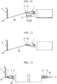
- FIGs. 7 to 18 are views for describing the actions of the suture-fixing system 1 of this embodiment.
- the endoscope 50 is guided to the site to be sutured T, and the suturing instrument 20 is guided to the site to be sutured T via one of the endoscopic channels 52 of the endoscope 50.
- the suture-fixing system 1 is guided to a portion near the site to be sutured T via the endoscopic channel 52 different from the endoscopic channel 52 to which the suturing instrument 20 is attached in an insertion part 51 of the endoscope 50.
- the suture-fixing tool 3 is disposed inside the distal end of the outer sheath 2 of the suture-fixing system 1.
- the engaging portion 11 extends from the first opening 4 of the distal end of the suture-fixing tool 3. An amount of extension of the engaging portion 11 from the first opening 4 may be set to an extent at which suturing using the suturing instrument 20 is not obstructed.
- a wide operative field may be secured by housing the entire suture-fixing system 1 inside the endoscopic channel 52 as necessary.
- the entire suture-fixing system 1 may be rotated using a central line of the endoscopic channel 52 as a rotational center. In this case, the engaging portion 11 can be moved to a position at which the engaging portion 11 does not obstruct the suturing.
- the sutured state is caused not to loosen in a suture site by pulling the surgical suture 30 after passing the surgical suture 30 through the tissue by several stitches from a suturing start portion Ts.
- the endoscope 50 is caused to be moved together with the suturing instrument 20 in a direction in which the endoscope 50 is removed to the outside of the body to eliminate the loosening of the sutured state in the suture site.
- the suturing instrument 20 when the suturing instrument 20 is caused to be moved with respect to the endoscopic channel 52 in a direction in which the suturing instrument 20 is removed from the endoscopic channel 52 of the endoscope 50, the loosening of the sutured state in the suture site can also be eliminated.
- the suture-fixing tool 3 is arranged on a suturing end portion and the suture-fixing tool 3 is fixed to the surgical suture 30 such that the suturing end portion does not escape from the tissue.
- the surgical suture 30 is first caused to pass through the passage 6 of the suture-fixing tool 3 to fix the suture-fixing tool 3 to the surgical suture 30.
- a member (for example, the first delivery member 22) of the pair of delivery members 21 to which the suture needle 31 is connected is first inserted into the encircled area 12 formed by the engaging portion 11 extending from the first opening 4 of the distal side of the suture-fixing tool 3.
- the suture needle 31 is delivered from one of the pair of delivery members 21 to the other delivery member (for example, in this case, from the first delivery member 22 to the second delivery member 23) by closing the pair of delivery members 21 and then opening the pair of delivery members 21 again.
- the suture needle 31 passes through the encircled area 12 in the aforementioned opening and closing operation of the pair of delivery members 21.
- a portion of the surgical suture 30 also passes through the encircled area 12 together with the suture needle 31.
- the surgical suture 30 is pulled by drawing the pair of delivery members 21 into the endoscopic channel 52 such that the site to be sutured T is sutured by the surgical suture 30 without loosening.
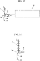
- the lead-in tool 10 is moved from the distal end of the outer sheath 2 toward the proximal end while the suture needle 31 is held by the pair of delivery members 21 through, for example, a manual operation of the user.
- the engaging portion 11 disposed at the distal end of the lead-in tool 10 is moved toward the proximal end together with the lead-in tool 10.
- the engaging portion 11 is moved from the first opening 4 of the distal side of the suture-fixing tool 3 toward the second opening 5 of the proximal side of the suture-fixing tool 3 via an inside of the passage 6.
- the surgical suture 30 Since the surgical suture 30 is caused to pass through the encircled area 12 formed by the engaging portion 11, the surgical suture 30 is engaged with the engaging portion 11.
- the surgical suture 30 is moved from the first opening 4 of the distal side of the suture-fixing tool 3 to the second opening 5 of the proximal side of the suture-fixing tool 3 via the passage 6 together with the engaging portion 11.
- the surgical suture 30 is pulled outside of the endoscopic device insertion port 53 (refer to Fig. 7 ) at the proximal end of the endoscopic channel 52 by further moving the engaging portion 11 toward the proximal end after the surgical suture 30 is caused to pass through the second opening 5 of the proximal side of the suture-fixing tool 3.
- the surgical suture 30 is pulled outside of the endoscope 50 from the endoscopic device insertion port 53 such that the suture needle 31 is not drawn into the endoscopic channel 52.
- the suture-fixing tool 3 is pushed outside of the outer sheath 2 from the distal end of the outer sheath 2 by moving the pusher 13 toward the distal side of the outer sheath 2.
- the pusher 13 can be moved through, for example, a manual operation of the user or the like.
- the surgical suture 30 is locked to the passage 6 of the suture-fixing tool 3 by a frictional force at a temporarily fixing level.
- the suture-fixing tool 3 is pushed by the pusher 13 to the distal side, the suture-fixing tool 3 is introduced and reaches a suturing end portion Te in the tissue along the surgical suture 30.
- the grasping forceps or the like which plastically deforms the suture-fixing tool 3 may be attached to the endoscopic channel 52 of the two endoscopic channels 52 to which the suture-fixing system 1 is not attached.
- the suture-fixing tool 3 can be plastically deformed by the grasping forceps or the like attached to the endoscopic channel 52.
- the grasping forceps or the like which plastically deforms the suture-fixing tool 3, may be inserted into the endoscopic channel 52 to which the suture-fixing system 1 is attached when the grasping forceps or the like is used.
- the surgical suture 30 is left in the endoscopic channel 52, and the outer sheath 2, the lead-in tool 10, the engaging portion 11, and the pusher 13 are removed from the endoscopic channel 52 before the grasping forceps or the like is inserted.
- the grasping forceps or the like can plastically deform the suture-fixing tool 3 when the grasping forceps or the like is inserted into the endoscopic channel 52 in which only the surgical suture 30 remains and extending the grasping forceps or the like to the suture-fixing tool 3.
- the inner surface of the passage 6 of the suture-fixing tool 3 comes into close contact with an outer surface of the surgical suture 30 when the suture-fixing tool 3 is plastically deformed, and the surgical suture 30 is thus fixed to the suture-fixing tool 3 as shown in Fig. 18 .
- the surgical suture 30 can be easily drawn into the suture-fixing tool 3 while the surgical suture 30 is stretched to eliminate the loosening of the surgical suture 30 after the surgical suture 30 is locked to the tissue to suture the tissue.
- the suture-fixing tool 3 can be attached to the suturing end portion Te even while the surgical suture 30 is stretched to eliminate the loosening of the surgical suture 30.
- the surgical suture 30 is easily fixed in the suturing of the tissue.
- the suture-fixing tool 3 can be pushed to the distal side along the surgical suture 30 while the surgical suture 30 is inserted into the pusher 13. For this reason, according to the suture-fixing system 1 of this embodiment, the suture-fixing tool 3 can be easily moved to the suturing end portion Te.
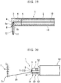
- Fig. 19 is a cross-sectional view showing a constitution of this modified example.
- Fig. 20 is a view for describing an action of a suture-fixing system of this modified example.
- a suture-fixing tool 3 includes a lateral opening 8 which communicates with the passage 6 and is opened in a lateral surface of the suture-fixing tool 3.
- the lateral opening 8 is formed in the lateral surface near the first opening 4 of the distal side between the first opening 4 and the second opening 5 described in the aforementioned first embodiment.
- the lateral opening 8 of this modified example is used instead of the first opening 4 of the aforementioned first embodiment.
- the engaging portion 11 described in the aforementioned first embodiment can pass the surgical suture 30 through the suture-fixing tool 3 as in the aforementioned first embodiment by drawing the surgical suture 30 from the lateral opening 8 of the suture-fixing tool 3 to the passage 6 and further drawing the surgical suture 30 to the second opening 5 of the proximal side.
- the lateral opening 8 of this modified example is formed as a slit having a shape in which a notch is formed in an outer wall portion of the suture-fixing tool 3 in a direction of a surface perpendicular to a central line of the passage 6 of the suture-fixing tool 3.
- the slit (the lateral opening 8) includes a wall surface 8a in a distal side and a wall surface 8b in a proximal side in a direction of the central line of the passage 6 of the suture-fixing tool 3.
- the engaging portion 11 can be held in a direction in which the surgical suture 30 easily passes through the encircled area 12 when the surgical suture 30 is caused to pass through the encircled area 12 using the suturing instrument 20.
- the engaging portion 11 is held such that the engaging portion 11 comes into contact with the wall surface 8a of the distal side in the slit (the lateral opening 8).
- the engaging portion 11 is bent in an L shape and protrudes to outside from the lateral surface of the suture-fixing tool 3, the surgical suture 30 can easily pass beside the suture-fixing tool 3.
- the engaging portion 11 is held such that the engaging portion 11 comes into contact with the wall surfaces 8a and 8b in the slit.
- the wall surfaces 8a and 8b extend at the distal side and the proximal side in the direction of the surface perpendicular to the central line of the passage 6 of the suture-fixing tool 3.
- the encircled area 12 formed by the engaging portion 11 is open in a circumferential direction of the suture-fixing tool 3 beside the lateral surface of the suture-fixing tool 3.
- the surgical suture 30 can be moved in the circumferential direction beside the lateral surface of the suture-fixing tool 3 using the suturing instrument 20 to pass through the encircled area 12.
- the suture-fixing tool 3 is arranged on a suturing end portion Te as in the aforementioned embodiment after the surgical suture 30 is passed through the suture-fixing tool 3, and the suture-fixing tool 3 can thus be fixed to the surgical suture 30.
- the engaging portion 11 advances and retracts in the direction of the central line of the endoscopic channel 52.
- the engaging portion 11 since the engaging portion 11 is inserted into the lateral opening 8, the engaging portion 11 advances and retracts in a direction which is inclined with respect to the central line of the endoscopic channel 52.
- the engaging portion 11 can be moved toward the pair of delivery members 21 of the suturing instrument 20, for example, by rotating the outer sheath 2 using the central line of the endoscopic channel 52 as the rotational center. Therefore, in this modified example, the engaging portion 11 can be easily arranged at a position at which the pair of delivery members 21 of the suturing instrument 20 can easily pass through the encircled area 12.
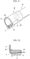
- FIG. 21 is a partial cross-sectional view showing a portion of a suture-fixing system in the second embodiment of the present invention.
- Fig. 22 is a cross-sectional view showing a suture-fixing tool of the suture-fixing system.
- a cap 40 which can be attached to a distal end of an insertion part 51 in a well-known endoscope 50 is provided instead of the outer sheath 2 of the suture-fixing system 1 described in the aforementioned first embodiment.
- This embodiment includes an engaging portion 43 fixed to a suture-fixing tool 3 instead of the engaging portion 11 described in the aforementioned first embodiment.
- the lead-in tool 10 described in the aforementioned first embodiment is inserted into one of endoscopic channels 52 of the endoscope 50 before a suture-fixing system 1 is used.
- the cap 40 includes a cylindrical main body 41 to which a distal end of the insertion part 51 of the endoscope 50 can be inserted and a holding portion 42 which holds the suture-fixing tool 3 in the main body 41.
- the main body 41 is, for example, transparent so that it does not obstruct an imaging field of vision of the endoscope 50.
- a size and a shape of an opening of a distal side of the main body 41 are constituted such that usage of a medical instrument or the like which extends from the endoscopic channels 52 of the endoscope 50 is not obstructed.
- the suture-fixing tool 3 described in the aforementioned first embodiment is inserted into the holding portion 42.
- the holding portion 42 locks an outer surface of the suture-fixing tool 3 by friction to hold the suture-fixing tool 3.
- the engaging portion 43 is a flexible linear member. One end of the engaging portion 43 is fixed to the suture-fixing tool 3, and the other end thereof is connected to the lead-in tool 10. In this embodiment, the engaging portion 43 and the lead-in tool 10 are integrally molded with each other.
- the engaging portion 43 and the lead-in tool 10 are constituted by a series of linear members, one end of which is fixed to the suture-fixing tool 3, and the other end of which is pulled outside of the endoscope 50 via the endoscopic channel 52.
- Fig. 22 shows a state in which the engaging portion 43 is attached to the suture-fixing tool 3.
- the engaging portion 43 is inserted into a passage 6 of the suture-fixing tool 3 from the second opening 5 of a proximal side of the suture-fixing tool 3.
- the engaging portion 43 extends from the first opening 4 at the distal end of the suture-fixing tool 3 to a more distal position.
- the engaging portion 43 is folded at a distal portion of the suture-fixing tool 3, and is inserted into the passage 6 of the suture-fixing tool 3 again from the first opening 4 at the distal end of the suture-fixing tool 3.
- the engaging portion 43 extends from the second opening 5 at the proximal end of the suture-fixing tool 3 to a more proximal position.
- a portion which extends from the opening (the first opening 4) at the distal end of the suture-fixing tool 3 in the engaging portion 43 (hereinafter referred to as a distal side-extending portion of the engaging portion 43) forms an encircled area 12 that is big enough that the engaging portion 43 can be put around an outer circumference of the main body 41.
- the distal side-extending portion of the engaging portion 43 is attached to the main body 41.
- the engaging portion 43 of the portion in which the encircled area 12 is formed is arranged at a position at which the imaging field of vision is not obstructed by the endoscope 50.
- the distal side-extending portion of the engaging portion 43 forms the encircled area 12 that is big enough that the engaging portion 43 can be put around the outer circumference of the main body 41 and is attached to the main body 41. For this reason, the medical instrument, which extends from the endoscopic channels 52 when used, passes through the encircled area 12 without being caught by the distal side-extending portion.
- Figs. 23 to 31 are views for describing the actions of the suture-fixing system 1 of this embodiment.
- the suturing instrument 20 described in the aforementioned first embodiment when the suturing instrument 20 described in the aforementioned first embodiment is attached to the endoscopic channel 52 of the endoscope 50, and a site to be sutured T is sutured, as shown in Fig. 23 , the suturing instrument 20 passes through the encircled area 12 formed by the engaging portion 43 in a direction from a proximal side to a distal side and is guided to the site to be sutured T.
- the suturing instrument 20 passes through the encircled area 12 in a direction from the distal side to the proximal side in an opposite direction and returns after the surgical suture 30 is locked to tissue.
- a user of the suture-fixing system 1 moves the insertion part 51 of the endoscope 50 such that the suture-fixing tool 3 is at a suturing end portion Te of the tissue.
- the user moves the insertion part 51 of the endoscope 50 such that the first opening 4 at the distal end of the suture-fixing tool 3 comes into contact with the suturing end portion Te of the tissue.
- the suture-fixing tool 3 When the suture-fixing tool 3 is arranged on the suturing end portion Te of the tissue while the surgical suture 30 is pulled by the suturing instrument 20, the suture-fixing tool 3 approaches the suturing end portion Te of the tissue while the surgical suture 30 does not loosen in the suture site.
- the engaging portion 43 which forms the encircled area 12, is drawn from the first opening 4 of the distal end of the suture-fixing tool 3 into the passage 6.
- the engaging portion 43 which is drawn into the passage 6, moves the surgical suture 30 from the first opening 4 of the distal end of the suture-fixing tool 3 into the passage 6.
- the lead-in tool 10 is moved toward the proximal end so that the engaging portion 43 passes through the passage 6.
- the engaging portion 43 is pulled outside from the second opening 5 of the proximal end of the suture-fixing tool 3 together with the surgical suture 30.
- the surgical suture 30 is temporarily fixed to the suture-fixing tool 3 as in the aforementioned first embodiment in a state in which the surgical suture 30 is arranged inside the suture-fixing tool 3.
- the user cuts the lead-in tool 10 or the engaging portion 43 in the endoscopic channel 52 as shown in Fig. 28 using the scissors forceps or the like (not shown).
- the suture-fixing tool 3 When the lead-in tool 10 or the engaging portion 43 is cut, the suture-fixing tool 3 is moved outside of the cap 40 by moving the cap 40 and the endoscope 50 toward the proximal end. The suture-fixing tool 3 is placed on the suturing end portion Te of the tissue.
- the suture-fixing tool 3 is fixed to the surgical suture 30 as shown in Fig. 31 by plastically deforming the suture-fixing tool 3 using the grasping forceps or the like as shown in Fig. 30 as in the aforementioned first embodiment.
- the suture-fixing system 1 of this embodiment accomplishes the same effect as the aforementioned first embodiment.
- the suture-fixing tool 3 can be fixed to the surgical suture 30.
- Fig. 32 is a cross-sectional view showing a constitution of a suture-fixing system of this modified example.
- Fig. 33 is a view for describing an action of the suture-fixing system.
- a holding portion 42 includes an external sheath 45.
- An external source 45 movably holds the pusher 13 described in the aforementioned first embodiment. It is noted that, in this modified example, the pusher 13 need not have a cylindrical shape.
- the external sheath 45 is a flexible cylindrical member.
- the external sheath 45 can be attached to an outer surface of an insertion part 51 of an endoscope 50 via a cylindrical sleeve 46.
- a binding band, a tape, etc. may be used to fix the external sheath 45 to the outer surface of the insertion part 51.
- the external sheath 45 is movably inserted into the holding portion 42.
- a suture-fixing tool 3 is attached inside a distal end of the external sheath 45.
- the external sheath 45 can be moved in the sleeve 46 and the holding portion 42 toward a distal end of the endoscope 50 such that the suture-fixing tool 3 is arranged on a suturing end portion Te of tissue. For this reason, the external sheath 45 can move the external sheath 45 toward the distal end while the surgical suture 30 is pulled using the suturing instrument 20 in a state in which the surgical suture 30 passes through the encircled area 12. As described above, when the external sheath 45 is moved toward the distal end, the suture-fixing tool 3 attached to the distal end of the external sheath 45 is also guided to the suturing end portion Te of the tissue.
- the pusher 13 is further used from this state as in the first embodiment so that the suture-fixing tool 3 is released from the external sheath 45.
- the suture-fixing tool 3 can be moved to the suturing end portion Te of the tissue more easily than in the second embodiment.
- the pusher 13 disposed inside the external sheath 45 enables the suture-fixing tool 3 to be released from the external sheath 45 through a simple operation.
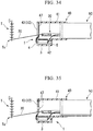
- Fig. 34 is a cross-sectional view showing a constitution of a suture-fixing system of this modified example.
- Fig. 35 is a cross-sectional view showing another constitution example in this modified example.
- a housing portion 47 which temporarily attaches an engaging portion 43 is provided inside a main body 41 of a cap 40.
- the housing portion 47 includes, for example, a recessed shape which extends in a circumferential direction of the cap 40.
- the housing portion 47 can temporarily attach the annular engaging portion 43 along the recessed shape when the engaging portion 43 enters the cap 40 in a state in which the engaging portion 43 forms an encircled area 12 in an inner circumferential direction of the cap 40.
- the engaging portion 43 is held in the housing portion 47.
- the encircled area 12 with a shape along the inner circumferential surface of the cap 40 is formed inside the engaging portion 43 held in the housing portion 47.
- the engaging portion 43 when the engaging portion 43 returns to the annular shape due to a restoring force of the engaging portion 43 itself to form the encircled area 12, the engaging portion 43 may be adapted to be locked to the housing portion 47 due to the restoring force of the engaging portion 43.
- an inner surface of the housing portion 47 may be engaged with an outer surface of the engaging portion 43 which forms the encircled area 12 in a frictional manner so that the housing portion 47 holds the engaging portion 43.
- the housing portion 47 may have a different constitution from that of the above description.
- the housing portion 47 may be a hooking member which holds a portion of the engaging portion 43 which forms the encircled area 12 near an inner surface of the main body 41.
- the hooking member constituting the housing portion 47 has enough holding force that the engaging portion 43 is released by an amount of force by which the lead-in tool 10 pulls the engaging portion 43.
- the encircled area 12 is formed by the engaging portion 43 arranged along the inner surface of the main body 41 inside the main body 41. For this reason, the surgical suture 30 is enabled to pass through the encircled area 12 using a medical instrument such as the suturing instrument 20 as in the aforementioned second embodiment.
- the suture-fixing system 1 when the number of endoscopic channels 52 is insufficient in the endoscope 50 which is used with the suture-fixing system 1, the suture-fixing system 1 can be used by attaching an externally attached channel which is appropriately added to the endoscope 50.
- a suture-fixing system which is able to fix a surgical suture easily while the suturing of tissue being hard to be loosened can be provided.
Landscapes
- Health & Medical Sciences (AREA)
- Life Sciences & Earth Sciences (AREA)
- Surgery (AREA)
- Heart & Thoracic Surgery (AREA)
- Engineering & Computer Science (AREA)
- Biomedical Technology (AREA)
- Nuclear Medicine, Radiotherapy & Molecular Imaging (AREA)
- Medical Informatics (AREA)
- Molecular Biology (AREA)
- Animal Behavior & Ethology (AREA)
- General Health & Medical Sciences (AREA)
- Public Health (AREA)
- Veterinary Medicine (AREA)
- Surgical Instruments (AREA)
Applications Claiming Priority (2)
| Application Number | Priority Date | Filing Date | Title |
|---|---|---|---|
| JP2014104892 | 2014-05-21 | ||
| PCT/JP2015/062900 WO2015178182A1 (ja) | 2014-05-21 | 2015-04-28 | 糸固定システム |
Publications (2)
| Publication Number | Publication Date |
|---|---|
| EP3146907A1 true EP3146907A1 (de) | 2017-03-29 |
| EP3146907A4 EP3146907A4 (de) | 2018-02-07 |
Family
ID=54553856
Family Applications (1)
| Application Number | Title | Priority Date | Filing Date |
|---|---|---|---|
| EP15796497.4A Withdrawn EP3146907A4 (de) | 2014-05-21 | 2015-04-28 | Fadenfixiersystem |
Country Status (5)
| Country | Link |
|---|---|
| US (1) | US20170035413A1 (de) |
| EP (1) | EP3146907A4 (de) |
| JP (1) | JP5977896B2 (de) |
| CN (1) | CN106232025B (de) |
| WO (1) | WO2015178182A1 (de) |
Families Citing this family (10)
| Publication number | Priority date | Publication date | Assignee | Title |
|---|---|---|---|---|
| JP6669926B1 (ja) * | 2019-07-22 | 2020-03-18 | フォースエンジニアリング株式会社 | 結紮器 |
| CN115916068A (zh) | 2020-03-31 | 2023-04-04 | 波士顿科学国际有限公司 | 基于缝合线的闭合设备 |
| WO2022079788A1 (ja) * | 2020-10-13 | 2022-04-21 | オリンパス株式会社 | 牽引器具、牽引システム、縫合糸の牽引方法および縫合方法 |
| US12514578B2 (en) | 2020-10-23 | 2026-01-06 | EnVision Endoscopy, Inc. | Endoscopic suture cinch |
| CN116648197A (zh) * | 2020-10-23 | 2023-08-25 | 想象内窥镜公司 | 内窥镜缝合线束紧器 |
| WO2022232150A1 (en) | 2021-04-26 | 2022-11-03 | Boston Scientific Scimed, Inc. | Suture based closure device |
| KR102914382B1 (ko) | 2021-04-26 | 2026-01-16 | 보스톤 싸이엔티픽 싸이메드 인코포레이티드 | 봉합사 기반 봉합 디바이스 |
| CN120344203A (zh) | 2022-12-01 | 2025-07-18 | 波士顿科学国际有限公司 | 基于缝合线的闭合装置 |
| WO2025117796A1 (en) * | 2023-11-29 | 2025-06-05 | Conmed Corporation | Implant delivery system |
| WO2025187572A1 (ja) * | 2024-03-08 | 2025-09-12 | オリンパス株式会社 | 医療用マニピュレータおよび医療用マニピュレータシステム |
Family Cites Families (17)
| Publication number | Priority date | Publication date | Assignee | Title |
|---|---|---|---|---|
| US5984932A (en) * | 1996-11-27 | 1999-11-16 | Yoon; Inbae | Suturing instrument with one or more spreadable needle holders mounted for arcuate movement |
| JPH10277044A (ja) * | 1997-04-03 | 1998-10-20 | Yuichi Matsuzawa | 手術用縫合糸の結紮方法 |
| US6126665A (en) * | 1997-05-01 | 2000-10-03 | Yoon; Inbae | Surgical instrument with arcuately movable offset end effectors and method of using the same |
| US6004332A (en) * | 1997-05-01 | 1999-12-21 | Yoon; Inbae | Suturing instrument with multiple rotatably mounted offset needle holders and method of using the same |
| US6143005A (en) * | 1997-05-01 | 2000-11-07 | Yoon; Inbae | Suturing instrument with rotatably mounted offset needle holder and method of using the same |
| US5921993A (en) * | 1997-05-01 | 1999-07-13 | Yoon; Inbae | Methods of endoscopic tubal ligation |
| US6077277A (en) * | 1999-04-05 | 2000-06-20 | Starion Instruments, Inc. | Suture welding device |
| US6733509B2 (en) * | 2000-08-25 | 2004-05-11 | Sutura, Inc. | Suture cutter |
| JP4261814B2 (ja) * | 2001-04-04 | 2009-04-30 | オリンパス株式会社 | 組織穿刺システム |
| AU2006262498B2 (en) * | 2005-06-20 | 2011-11-03 | Nobles Medical Technologies, Inc. | Method and apparatus for applying a knot to a suture |
| US20070005079A1 (en) * | 2005-06-30 | 2007-01-04 | David Zarbatany | System, apparatus, and method for repairing septal defects |
| US8252005B2 (en) * | 2005-06-30 | 2012-08-28 | Edwards Lifesciences Corporation | System, apparatus, and method for fastening tissue |
| US20080154286A1 (en) * | 2006-12-21 | 2008-06-26 | Ryan Abbott | Systems and Methods for Treating Septal Defects with Capture Devices and Other Devices |
| US8540735B2 (en) * | 2010-12-16 | 2013-09-24 | Apollo Endosurgery, Inc. | Endoscopic suture cinch system |
| SG192154A1 (en) * | 2011-01-25 | 2013-08-30 | Univ Kagawa Nat Univ Corp | Suture device |
| US20130217957A1 (en) * | 2012-02-16 | 2013-08-22 | Usgi Medical, Inc. | Devices and methods for the endolumenal treatment of obesity |
| US9138214B2 (en) * | 2012-03-02 | 2015-09-22 | Abbott Cardiovascular Systems, Inc. | Suture securing systems, devices and methods |
-
2015
- 2015-04-28 CN CN201580020728.3A patent/CN106232025B/zh active Active
- 2015-04-28 JP JP2015557278A patent/JP5977896B2/ja active Active
- 2015-04-28 WO PCT/JP2015/062900 patent/WO2015178182A1/ja not_active Ceased
- 2015-04-28 EP EP15796497.4A patent/EP3146907A4/de not_active Withdrawn
-
2016
- 2016-10-19 US US15/298,108 patent/US20170035413A1/en not_active Abandoned
Also Published As
| Publication number | Publication date |
|---|---|
| CN106232025A (zh) | 2016-12-14 |
| EP3146907A4 (de) | 2018-02-07 |
| WO2015178182A1 (ja) | 2015-11-26 |
| CN106232025B (zh) | 2019-06-18 |
| US20170035413A1 (en) | 2017-02-09 |
| JP5977896B2 (ja) | 2016-08-24 |
| JPWO2015178182A1 (ja) | 2017-04-20 |
Similar Documents
| Publication | Publication Date | Title |
|---|---|---|
| EP3146907A1 (de) | Fadenfixiersystem | |
| US9788831B2 (en) | Endoscopic suture cinch system with replaceable cinch | |
| US10448946B2 (en) | Endoscopic suture cinch | |
| EP2813185B1 (de) | Probenentnahmevorrichtung mit wiederverwendbarem Schaft mit auswechselbarem Beutel | |
| JP5242181B2 (ja) | 縫合器 | |
| EP3351189B1 (de) | Endoskopisches behandlungsinstrument | |
| EP2651312B1 (de) | Endoskopisches nahtcinchsystem | |
| US8308744B2 (en) | Endoscopic treatment instrument | |
| JP5259201B2 (ja) | 縫合具 | |
| EP4631444A2 (de) | Hämostaseclip | |
| EP3351187B1 (de) | Endoskopbehandlungsinstrument | |
| EP3534805B1 (de) | Benutzergesteuerte nachladbare clip-kassette | |
| EP3915494B1 (de) | Mehrfaches öffnen/schliessen einer klemme | |
| KR101880423B1 (ko) | 봉합사를 안내하기 위한 방법 및 장치 | |
| EP3351186A1 (de) | Endoskopbehandlungsinstrument | |
| US20170360435A1 (en) | Surgical closure apparatus and method | |
| JP2006212240A (ja) | 医療用縫合結紮具及び医療用縫合結紮装置 | |
| JP6291046B2 (ja) | 縫合糸の経骨挿入用完全機器 | |
| EP2574307B1 (de) | Implantatseinführer | |
| US20160038140A1 (en) | Suture device | |
| JP4594953B2 (ja) | 内視鏡用処置具及び縫縮器具 | |
| US20140316440A1 (en) | Multiple clip endoscopic tissue clipping system and device | |
| US20210251624A1 (en) | Suture passing device and methods of use thereof | |
| KR200483498Y1 (ko) | 매듭 유동 구속형 루프 조립체 | |
| JP6736658B2 (ja) | ストップガードを有する外科用器具 |
Legal Events
| Date | Code | Title | Description |
|---|---|---|---|
| STAA | Information on the status of an ep patent application or granted ep patent |
Free format text: STATUS: THE INTERNATIONAL PUBLICATION HAS BEEN MADE |
|
| PUAI | Public reference made under article 153(3) epc to a published international application that has entered the european phase |
Free format text: ORIGINAL CODE: 0009012 |
|
| STAA | Information on the status of an ep patent application or granted ep patent |
Free format text: STATUS: REQUEST FOR EXAMINATION WAS MADE |
|
| 17P | Request for examination filed |
Effective date: 20161123 |
|
| AK | Designated contracting states |
Kind code of ref document: A1 Designated state(s): AL AT BE BG CH CY CZ DE DK EE ES FI FR GB GR HR HU IE IS IT LI LT LU LV MC MK MT NL NO PL PT RO RS SE SI SK SM TR |
|
| AX | Request for extension of the european patent |
Extension state: BA ME |
|
| DAV | Request for validation of the european patent (deleted) | ||
| DAX | Request for extension of the european patent (deleted) | ||
| A4 | Supplementary search report drawn up and despatched |
Effective date: 20180109 |
|
| RIC1 | Information provided on ipc code assigned before grant |
Ipc: A61B 17/04 20060101AFI20180103BHEP |
|
| STAA | Information on the status of an ep patent application or granted ep patent |
Free format text: STATUS: THE APPLICATION IS DEEMED TO BE WITHDRAWN |
|
| 18D | Application deemed to be withdrawn |
Effective date: 20201103 |