EP3147041B1 - Procédé et appareil de cintrage d'un produit semi-fini métallique - Google Patents
Procédé et appareil de cintrage d'un produit semi-fini métallique Download PDFInfo
- Publication number
- EP3147041B1 EP3147041B1 EP16189438.1A EP16189438A EP3147041B1 EP 3147041 B1 EP3147041 B1 EP 3147041B1 EP 16189438 A EP16189438 A EP 16189438A EP 3147041 B1 EP3147041 B1 EP 3147041B1
- Authority
- EP
- European Patent Office
- Prior art keywords
- bending
- die
- bending punch
- finished product
- semi
- Prior art date
- Legal status (The legal status is an assumption and is not a legal conclusion. Google has not performed a legal analysis and makes no representation as to the accuracy of the status listed.)
- Active
Links
Images

Classifications
-
- B—PERFORMING OPERATIONS; TRANSPORTING
- B21—MECHANICAL METAL-WORKING WITHOUT ESSENTIALLY REMOVING MATERIAL; PUNCHING METAL
- B21D—WORKING OR PROCESSING OF SHEET METAL OR METAL TUBES, RODS OR PROFILES WITHOUT ESSENTIALLY REMOVING MATERIAL; PUNCHING METAL
- B21D5/00—Bending sheet metal along straight lines, e.g. to form simple curves
- B21D5/02—Bending sheet metal along straight lines, e.g. to form simple curves on press brakes without making use of clamping means
-
- B—PERFORMING OPERATIONS; TRANSPORTING
- B21—MECHANICAL METAL-WORKING WITHOUT ESSENTIALLY REMOVING MATERIAL; PUNCHING METAL
- B21D—WORKING OR PROCESSING OF SHEET METAL OR METAL TUBES, RODS OR PROFILES WITHOUT ESSENTIALLY REMOVING MATERIAL; PUNCHING METAL
- B21D5/00—Bending sheet metal along straight lines, e.g. to form simple curves
- B21D5/02—Bending sheet metal along straight lines, e.g. to form simple curves on press brakes without making use of clamping means
- B21D5/0209—Tools therefor
Definitions
- the invention relates to a method for bending a metallic semi-finished product, a device for bending a metallic semi-finished product, and a metallic component.
- Bending is a common method for reshaping metal parts, in particular sheet metal parts. According to the DIN 8586 standard, this is understood to mean “the bending of a solid body, the plastic state being brought about essentially by bending stress”.
- a workpiece e.g. a blank or another semi-finished product
- a workpiece made of metal is subjected to at least three points of force in such a way that a bending moment results, which ensures plastic, i.e. permanent deformation.
- Bending forming is typically carried out as cold forming, but it is also possible as hot forming at elevated workpiece temperatures.
- a large number of different methods are known in the prior art for the industrial implementation of a bending process, the above-mentioned standard distinguishing primarily according to the tool movement.
- a stationary bending die and a movable bending punch usually work together to carry out the bending process.
- the bending die forms a die with a normally V-shaped or U-shaped opening into which the workpiece is pressed by means of the bending punch.
- the process types free bending, die bending (embossing bending) and three-point bending all of which have in common that the workpiece initially rests on the bending die, more precisely on its edges, and in an intermediate, initially only relatively small-area (or quasi linear) area comes into contact with the punch.
- This area can be referred to as the working edge (or lower edge or bending edge) of the punch.
- the bending punch has an approximately wedge-shaped or triangular cross-section, at least in the area in which contact with the workpiece occurs. in the Further progress, the application of force to the workpiece by the bending punch leads to the workpiece being plastically deformed in the area of the deformation zone near the working edge.
- the DE 19938 452 A1 discloses a forming tool, in particular a drawing tool, which is provided, for example, for forming sheet metal parts.
- the molding tool consists of a fine zinc alloy and has a chromium-containing surface coating, which is intended to improve the stability for production of medium quantities.
- the surface coating can have a roughened structure, which serves to improve lubricant adhesion to the mold.
- the JP 2014/076464 A relates to a bending device with a bending punch and a die. This can be used to bend a steel plate.
- the bending punch has a recess in the area of the working edge into which an insert is inserted.
- This insert can for example consist of special steel with a Rockwell hardness of 58 or 60.
- DE GB 1,206,644 A discloses an apparatus and method for drawing a thermoplastic material. During the drawing process, a punch interacts with a die. A problem here is that certain areas can experience thinning when pulled, which can cause the material to tear in extreme cases. In order to restrict or prevent the thermoplastic material from flowing which is associated with the thinning, it is provided that the stamp has a roughened surface.
- the WO 2008/050457 A1 shows a bending device with a bending punch and a die, both of which are made, for example, of high-carbon steel or chromium-molybdenum steel can exist.
- a hard material layer is produced in some areas in the area of the working edge of the bending punch. This only extends to a central part of the entire working edge in order to prevent increased wear there when bending smaller parts.
- the invention is therefore based on the object of improving the precision and process stability when bending in the die.
- the object is achieved according to the invention by a method according to claim 1, a device according to claim 8 and a metallic workpiece according to claim 9.
- the invention provides a method for bending a metallic semi-finished product.
- the semifinished product is metallic in the sense that it consists at least predominantly of metal, it being conceivable that it has an at least partially non-metallic coating.
- the metallic semi-finished product can in particular be a sheet metal part, for example a plate that has been cut from a coil. As a rule, the metallic semi-finished product consists at least predominantly of steel.
- the process is carried out with a punch and a die.
- the bending punch has a radius area forming a bending edge and leg areas adjoining it on both sides.
- the bending punch is basically constructed in a known manner and usually consists mainly of metal, for example steel.
- the radius area In the operating state, the radius area generally corresponds to the lower edge of the bending punch and represents the area that defines at least the minimum possible inner bending radius.
- the radius area has a curved surface, the curvature generally being uniform and being characterized by a single radius, although in principle deviations from this would be conceivable within the scope of the invention.
- “Working edge” here denotes an edge of the bending punch around which a workpiece is bent.
- the position of the radius area also defines a bending axis, ie the axis along which the bending of a workpiece takes place.
- the leg areas which can also be referred to as flanks, adjoin the radius area on both sides, and of course they are transverse to the direction of the working edge connect to the radius area.
- the legs of the bent workpiece adjoining the bent area can come into contact with these leg areas, for example during die bending (stamping bending).
- the surfaces of the leg regions of the bending punch are inherently straight or flat.
- the leg regions preferably run at an angle to one another, so that a wedge-shaped cross section normally results overall, in which the radius region forms the tip of the wedge.
- the die forms a die with a depression, the shape of which prescribes at least a maximum possible deformation of the semi-finished product.
- the bending punch and the die form parts of a bending device, for example a press brake or a bending tool. They can be permanently integrated into the bending device or they can be designed as modules that can be exchanged as required.
- the semi-finished product is pressed into the die by applying force through the bending punch and reshaped between the bending punch and the die.
- the workpiece normally initially rests on the die and there is initially contact between the radius area of the bending punch and the semi-finished product.
- the bending punch remains in contact with the semifinished product, at least with the radius area, even in the further course of the bending process.
- the process according to the invention is preferably designed as a cold forming process, i.e. the semi-finished product is not specifically heated in preparation for the bending process. Alternatively, it can also be carried out as a hot forming process.
- the bending punch has a roughened surface extending at least over part of the radius area.
- “Roughened” here means that a higher roughness was set in the specified surface during the manufacturing process. This can be achieved through various measures, which will be discussed below.
- the so-called “mean roughness” R a can be used as a measure of the roughness. This corresponds to the arithmetic mean of the absolute deviation of the height values of all Measurement points of a surface from the center line (the center line being the arithmetic mean of the height values of all measurement points).
- the roughness of the surface mentioned is greater than the roughness of adjacent surface parts of the bending punch.
- the roughness of the roughened surface can also preferably be greater than the roughness of the semi-finished product to be bent. At least parts of the roughened surface of the bending punch come into contact with the semifinished product at the beginning of the bending process, the increased roughness ensuring increased friction, which minimizes undesired relative movement of the semifinished product with respect to the bending punch.
- the raised surface structures of the roughened surface can be transferred to the semifinished product, so that a plastic deformation of the surface of the semifinished product and effective interlocking takes place.
- the roughened surface (as a kind of negative shape) is reproduced in the surface of the semi-finished product to a certain extent.
- the extent to which this happens depends on the one hand on the pressure applied and on the other hand on the ratio of the hardness of the two surfaces.
- the roughened surface can be contiguous or also non-contiguous, or several roughened surfaces can be provided.
- the roughness can be constant within the roughened surface, but here again individual areas can be more roughened than others. Overall, the roughness can be selected over a wide range as required, ie depending on the extent to which a relative movement is to be feared.
- the set surface roughness is usually selected depending on the bending task.
- the mean roughness is typically in the micrometer range or below, for example between 0.1 ⁇ m and 50 ⁇ m.
- the leg areas can enclose a wide variety of angles with one another, although bending angles in practice are normally between 10 ° and 170 °, which means that there is at least an upper limit for the angle between the leg areas. They preferably enclose an angle between 80 ° and 100 °, more preferably between 85 ° and 95 °, ie they preferably form approximately or exactly a right angle with one another. They can be inclined symmetrically or asymmetrically with respect to the direction of movement of the bending punch (which usually corresponds to the vertical).
- both leg areas can have an inclination of 45 °, or, for example, one may have an incline of 30 ° and the other an incline of 60 °.
- the roughening according to the invention can be advantageous in particular in the case of asymmetrical configurations, since in these cases there is also an asymmetrical force distribution which can increase the risk of displacement.
- the process can be carried out as free bending or as three-point bending.
- the semi-finished product is only bent so far that it does not reach the bottom of the die, i.e. it only rests on the edges of the die. This means that the legs of the semi-finished product do not come into contact with the flanks of the die.
- the semifinished product is bent so far that it touches the die on the one hand at the edges and on the other hand in between in the area opposite the radius area of the bending punch.
- the die usually has a U-shaped opening. In the method according to the invention, however, it is preferred that die bending takes place, the bending punch and the die enclosing the semifinished product at least predominantly without a gap.
- This process allows the highest level of precision, as the set shape of the semi-finished product (apart from reshaping processes) is completely determined by the shape of the punch and die that are matched to one another.
- the process is also known as embossing bending, especially when the final pressures are high.
- there is a flat contact between the workpiece and the die while the contact is essentially linear in both free bending and three-point bending.
- the die has surface areas that correspond to the leg areas and the radius area of the bending punch, in the latter case the die must provide a radius that is greater than that of the radius area by the thickness of the semi-finished product.
- the roughened surface is advantageously arranged at least predominantly in the radius area; at most, smaller parts of the surface mentioned lie outside the radius area.
- the roughened surface is preferably limited to the radius area. In other words, at least parts of the radius area have a higher roughness than the leg areas adjoining the radius area. The latter Normally, due to the process, there are no special requirements with regard to the surface roughness and, as is known in the prior art for bending punches, can be made smooth. Of course, the entire radius area can also be roughened. It has been shown that it is sufficient for a reliable bending process if the roughened surface is only provided within the radius area.
- the roughened surface is limited to a central area along the working edge (i.e. along the direction of the working edge) with the cut-out of end areas. That is, the end areas mentioned, so to speak the ends of the bending punch, do not have a roughened surface. This reduces the risk of any cracks spreading under operational stress due to the surface structure. For a reliable frictional connection it is sufficient if the intermediate area in between is completely or partially roughened. This configuration can in particular be combined with the above configuration so that the roughened surface is limited to a central area of the radius area.
- the end areas can take up a relatively small part of the length (that is to say the extension along the working edge) of the bending punch, with the exact amount being able to be defined in an application-specific manner. For example, it can be a maximum of 10% or a maximum of 5%.
- the roughened surface can be formed by a surface profile which is set in a primary, reshaping and / or abrasive manner.
- the surface profile here is usually the profile of the surface of the base body of the punch, which normally consists of steel.
- the desired surface profile could have been created directly during the primary forming of the punch or in a subsequent forming step (for example by means of hot forming).
- the shape of the bending punch is set by mechanical processing (milling or the like) before a surface treatment takes place.
- Those parts that are to be roughened can be subjected to a removal treatment, whereby a surface profile is generated.
- the surface can then be coated.
- both machining and chemical, electrochemical machining are referred to as “removing” machining and / or thermal removal.
- die sinking can take place.
- the roughened surface is formed by a coating with hard material particles.
- Hard material particles are in particular those particles that have a higher hardness than the semi-finished product to be processed. Such particles can consist, for example, of diamond, boron nitride, silicon carbide or other known hard materials.
- the bonding of the particles to the surface of the bending punch can take place via a binding agent (for example a synthetic resin) or by electroplating metal, whereby the particles bond with the surface. Other methods are also possible.
- the method according to the invention is particularly suitable for semi-finished products, for example sheet metal blanks, of greater thickness.
- the semi-finished product therefore has a thickness between 1 mm and 20 mm, preferably between 3 mm and 12 mm, more preferably between 5 mm and 10 mm, particularly preferably between 6 mm and 9 mm.
- This information relates in particular to steel sheets.
- the thickness of the semi-finished product to be formed means that a certain inner bending radius cannot be fallen below. Experience shows that the minimum possible bending radius roughly corresponds to the thickness of the semi-finished product. It therefore preferably corresponds to the values mentioned above in this regard.
- the inner bending radius also corresponds to the radius of the radius area. In other configurations (free bending, three-point bending), the radius of the radius area can also be smaller.
- the invention also provides a device for bending a metallic semi-finished product.
- the device comprises a bending punch with a radius area forming a working edge and leg areas adjoining it transversely to the working edge, as well as a die. It is set up to press the semifinished product into the die by applying the bending punch and to shape it between the bending punch and the die.
- the Bending punch has a roughened surface extending over at least part of the radius area.
- the device can be set up for embossing bending, the bending punch and the die being designed to enclose the semifinished product without a gap.
- the roughened surface can be limited to the radius area.
- the roughened surface along the working edge can also be limited to a central area with the cut-out of end areas.
- the roughened surface is preferably formed by an abrasive surface profile or by a coating with hard material particles.
- the device is advantageously set up to bend a semi-finished product that has a thickness between 1 mm and 20 mm, preferably between 3 mm and 12 mm, more preferably between 5 mm and 10 mm, particularly preferably between 6 mm and 9 mm.
- the radius area also advantageously defines an inner bending radius of at least 3 mm, preferably at least 5 mm, more preferably at least 7 mm.
- the invention also provides a metallic workpiece. This was produced from a metallic semi-finished product by bending according to the method according to the invention and / or with a device according to the invention. After the bending process, the workpiece can be either a semi-finished part or a finished part.
- steel parts that have been made from sheet metal are suitable.
- frame parts can be manufactured in automobile construction, e.g. for trucks. This also includes reinforcements for frame structures such as gusset plates or subframes.
- Such a workpiece according to the invention does not differ in the essential dimensions from a conventionally manufactured workpiece, but in the area acted upon by the roughened surface of the bending punch, small depressions are normally to be found, namely where the surface structure of the bending punch is under high Pressure on the surface of the workpiece. Since the exact structure of the roughened surface in In many cases it is coincidental and therefore unique for a particular bending punch, such a workpiece could in principle even be assigned to the bending punch with which it was manufactured by comparing the surface structure.
- Fig. 1 shows a perspective view of a bending punch 10 for a bending device 1 according to the invention according to a first embodiment.
- the side of the bending punch 10 which is at the top in the drawing is directed downwards in the installed state.
- the bending punch 10 has a radius area 11, which in the present case is curved with a radius of 9 mm.
- the radius area forms a working edge 12 along which a workpiece 30 can be bent.
- leg areas 13 of the bending punch 10 adjoin, which in the present case are inclined by 90 ° to one another, whereby the bending punch 10 has a wedge-shaped or V-shaped cross section.
- the bending punch 10 is constructed essentially symmetrically, with each of the leg regions 13 is inclined by 45 ° with respect to the plane of symmetry (which corresponds to the vertical in the installed state).
- the bending punch consists predominantly of steel, whereby at least the radius area 11 and the leg areas 13 can be surface-treated in order to achieve a higher hardness.
- a roughened surface 14 is formed along the entire radius area 11, which is only shown schematically in the figure, the indicated surface structures not being shown true to scale in any way.
- the mean roughness R a of the roughened surface 14 is 18 ⁇ m.
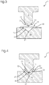
- Figures 3 and 4 show, in a highly schematic sectional view, the forming of a steel blank 30 by means of a bending device 1 (for example a bending press), into which the in Fig. 1 bending punch 10 shown is integrated.
- a bending device 1 for example a bending press
- the bending device 1 also comprises a die 20 on which the steel blank 30 rests at the beginning of the bending process, as in FIG Fig. 3 shown.
- the die 20 forms a recess with a concave sole 21, straight flanks 22 which are inclined by 45 ° with respect to the vertical and which merge into the horizontal via convex rounded edges 23.
- the die 20 is thus essentially V-shaped.
- the concave sole 21 has a radius of 16 mm, which corresponds to the sum of the radius of the radius area 11 and a thickness of 7 mm of the steel plate 30.
- the bending device 1 is thus set up for embossing bending, in which in the final stage of the process the steel blank 30 is enclosed between the bending punch 10 and the die 20 without a gap.
- the entire surface of the die 20 is made smooth in a similar way to the leg areas 13 of the bending punch 10. Due to the roughening of the surface 14 of the radius area 11 (and the associated higher mean roughness R a ) there is a significantly greater coefficient of static friction between this and a surface 31 of the steel blank 30 than between all other surfaces. This is noticeable at the beginning of the bending process, which is carried out in Fig. 3 is shown where only part of the radius area 11 comes into contact with the surface 31 of the steel blank 30. There is an engagement between the structures of the roughened surface 14 and the surface 31, even, as still with reference to FIG Figures 5 and 6 is explained, a deformation of the surface 31 takes place.
- the plate 30 is practically secured against undesired slipping in the area of the radius area 11, so that, as provided, only bending and sliding over the edges 23 takes place.
- the steel plate 30 forms a bend 33, which is laterally adjoined by legs 32 which are at an angle of 90 ° to one another.
- This state is in Fig. 4 shown. Since the position of the steel blank 30 relative to the radius area 11 is defined during the entire bending process, a particularly high dimensional accuracy can be achieved. In this way, for example, a gusset plate can be produced to reinforce a frame structure of a truck.
- Fig. 2 shows an alternative embodiment of a bending punch 10, which is also used in the in Figures 3 and 4 illustrated procedures can be used. It differs from the in Fig. 1 bending punch 10 shown in that the roughened surface 14 does not extend over the entire length of the working edge 12, but that it is limited to a central area 10.1, while end areas 10.2 are cut out. This configuration can, under certain circumstances, prevent the formation of increased cracks in the areas of the steel blank 30 that come into contact with the end areas 10.2.
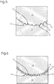
- Fig. 5 shows a section from a greatly enlarged and again not true to scale Fig. 4 , in which it can be seen that the roughened surface 14 is formed by a surface profile of the steel (and possibly surface-treated) surface of the punch 10.
- the surface profile was generated by die sinking, which results in a large number of elevations 15 (a few micrometers or fractions of micrometers in size) in the radius area 11.
- these elevations 15 press into the surface 31 of the steel plate 30, which on the one hand brings about an improved engagement of the two surfaces 14, 31, but on the other hand also brings about a plastic deformation of the surface 31, which on closer inspection of the finished workpiece is recognizable.
- a type of negative of the roughened surface 14 is formed there.
- Fig. 6 shows one Fig. 5 corresponding image section according to an alternative embodiment, in which the roughened surface 14 is not processed the metal surface, but by coating with hard material particles 16.
- the hard material particles 16 are again only shown schematically and not true to scale. This can be diamond particles, for example. These are also expressed, as in the Fig. 6 recognizable, into the surface 31 and cause a plastic deformation of the same.
- the hard material particles 16 can be connected to the surface of the radius area 11 by electroplating, for example, by metal deposition or by a binder based on synthetic resin.
- the corresponding metal deposits or the binding agent are in the Fig. 6 not shown for the sake of simplicity.
Landscapes
- Engineering & Computer Science (AREA)
- Mechanical Engineering (AREA)
- Bending Of Plates, Rods, And Pipes (AREA)
Claims (8)
- Procédé de cintrage d'un produit semi-fini métallique (30), en utilisant :- un poinçon de cintrage (10) qui présente une zone de rayon (11) formant une arête de travail (12), et présentant aussi des zones de flancs (13) contiguës, des deux côtés, à ladite zone de rayon, et- une matrice (20),procédé au cours duquel le produit semi-fini (30), sous l'effet de la sollicitation exercée par le poinçon de cintrage (10), est pressé dans la matrice (20) et déformé entre le poinçon de cintrage (10) et la matrice (20),
caractérisé
en ce que le poinçon de cintrage (10) présente une surface rugueuse (14) s'étendant au moins sur une partie de la zone de rayon (11), surface dont la rugosité est supérieure à la rugosité de parties de surface contiguës du poinçon de cintrage. - Procédé selon la revendication 1, caractérisé en ce qu'il se produit un cintrage par matriçage, où le poinçon de cintrage (10) et la matrice (20) entourent sans espacement le produit semi-fini (30).
- Procédé selon la revendication 1, caractérisé en ce que la surface rugueuse (14) est limitée à la zone de rayon (11).
- Procédé selon la revendication 1, caractérisé en ce que la surface rugueuse (14), le long de l'arête de travail (12), est limitée à une zone centrale (10.1), à l'exception des zones d'extrémités (10.2).
- Procédé selon la revendication 1, caractérisé en ce que la surface rugueuse (14) est formée par un profil de surface configuré en étant à enlèvement de matière.
- Procédé selon la revendication 1, caractérisé en ce que la surface rugueuse (14) est formée par un revêtement de particules de matière dure (16).
- Procédé selon la revendication 1, conçu de manière telle, que le produit semi-fini (30) présente une épaisseur comprise entre 3 mm et 12 mm, de préférence comprise entre 5 mm et 10 mm, de façon plus préférable comprise entre 6 mm et 9 mm.
- Dispositif (1) pour le cintrage d'un produit semi-fini métallique (30), où le dispositif (1) comprend :- un poinçon de cintrage (10) qui présente une zone de rayon (11) formant une arête de travail (12), et présentant aussi des zones de flancs (13) contiguës, des deux côtés, à ladite zone de rayon, et- une matrice (20),et ledit dispositif est conçu pour presser le produit semi-fini (30) dans la matrice (20) sous l'effet de la sollicitation exercée par le poinçon de cintrage (10), et pour déformer ledit produit semi-fini entre le poinçon de cintrage (10) et la matrice (20),
caractérisé
en ce que le poinçon de cintrage (10) présente une surface rugueuse (14) s'étendant au moins sur une partie de la zone de rayon (11), surface dont la rugosité est supérieure à la rugosité de parties de surface contiguës du poinçon de cintrage.
Priority Applications (1)
| Application Number | Priority Date | Filing Date | Title |
|---|---|---|---|
| PL16189438T PL3147041T3 (pl) | 2015-09-24 | 2016-09-19 | Sposób i urządzenie do gięcia metalowego półfabrykatu |
Applications Claiming Priority (1)
| Application Number | Priority Date | Filing Date | Title |
|---|---|---|---|
| DE102015116188.5A DE102015116188B4 (de) | 2015-09-24 | 2015-09-24 | Verfahren zum Biegen eines metallischen Halbzeugs |
Publications (2)
| Publication Number | Publication Date |
|---|---|
| EP3147041A1 EP3147041A1 (fr) | 2017-03-29 |
| EP3147041B1 true EP3147041B1 (fr) | 2021-02-24 |
Family
ID=56943418
Family Applications (1)
| Application Number | Title | Priority Date | Filing Date |
|---|---|---|---|
| EP16189438.1A Active EP3147041B1 (fr) | 2015-09-24 | 2016-09-19 | Procédé et appareil de cintrage d'un produit semi-fini métallique |
Country Status (3)
| Country | Link |
|---|---|
| EP (1) | EP3147041B1 (fr) |
| DE (1) | DE102015116188B4 (fr) |
| PL (1) | PL3147041T3 (fr) |
Family Cites Families (4)
| Publication number | Priority date | Publication date | Assignee | Title |
|---|---|---|---|---|
| SE334016B (fr) * | 1966-12-01 | 1971-04-05 | Borg Warner | |
| DE19938452A1 (de) | 1999-08-13 | 2001-02-15 | Bayerische Motoren Werke Ag | Formwerkzeug |
| WO2008050457A1 (fr) * | 2006-10-27 | 2008-05-02 | Komatsu Industries Corporation | Matrice et poinçon pour presse-plieuse |
| JP2014076464A (ja) * | 2012-10-10 | 2014-05-01 | Tagami Ii Ekusu:Kk | プレスブレーキ用パンチおよびダイ |
-
2015
- 2015-09-24 DE DE102015116188.5A patent/DE102015116188B4/de active Active
-
2016
- 2016-09-19 EP EP16189438.1A patent/EP3147041B1/fr active Active
- 2016-09-19 PL PL16189438T patent/PL3147041T3/pl unknown
Non-Patent Citations (1)
| Title |
|---|
| None * |
Also Published As
| Publication number | Publication date |
|---|---|
| DE102015116188B4 (de) | 2022-09-08 |
| DE102015116188A1 (de) | 2017-03-30 |
| PL3147041T3 (pl) | 2021-08-02 |
| EP3147041A1 (fr) | 2017-03-29 |
Similar Documents
| Publication | Publication Date | Title |
|---|---|---|
| DE112009001712B4 (de) | Werkstückbiegeverfahren | |
| EP2036631B1 (fr) | Procédé et dispositif destinés à la fabrication de pièces découpées dotées de surfaces de fonction agrandies | |
| EP3519121B1 (fr) | Procédé de fabrication d'éléments comportant une zone de fond adaptée | |
| DE102015220231B4 (de) | Vorrichtung zum Tiefziehen eines Blechzuschnittes mit Formwerkzeugen | |
| DE102009025821A1 (de) | Verfahren zur Herstellung eines Metallbauteils | |
| EP2508274B1 (fr) | Procédé et dispositif d'augmentation de la surface de portée d'une pièce obtenue par découpage fin ayant une dent, partie dentée ou analogue | |
| EP3565677B1 (fr) | Procédé de fabrication de pièces métalliques en feuille et dispositif associé | |
| EP2012951B1 (fr) | Procédé de fabrication d'une roue dentée | |
| DE102007056358A1 (de) | Umformwerkzeug sowie Verfahren zur Herstellung eines solchen Umformwerkzeugs | |
| AT508551B1 (de) | Stanzwerkzeug | |
| EP2596263B1 (fr) | Procédé de fabrication d'un support de garniture de frein | |
| DE102009003655A1 (de) | Blechplatine mit homogenem Dickenübergang | |
| EP3147041B1 (fr) | Procédé et appareil de cintrage d'un produit semi-fini métallique | |
| DE102008002736A1 (de) | Vorrichtung zur Bearbeitung einer Platte zu einem nanostrukturierten Formteil und ein Verfahren zur Herstellung desselben | |
| DE102009053534A1 (de) | Vorrichtung und Verfahren zum Umformen und/oder Vergüten von Blechbauteilen | |
| DE102013001919A1 (de) | Verfahren zur Erzeugung eines Durchgangslochs in einem metalischen Körper | |
| WO2018014989A1 (fr) | Procédé de fabrication d'un outil d'usinage de métaux et outil d'usinage de métaux ainsi fabriqué | |
| EP3519120B1 (fr) | Procédé de fabrication d'un composant par formage et pourvu d'une zone de paroi présentant des dimensions précises | |
| DE102015008171A1 (de) | Vorrichtung und Verfahren zum Bearbeiten eines Blechbauteils | |
| DE2138189B2 (de) | Matrize zur verformung von metallen | |
| EP4387783B1 (fr) | Procédé de fabrication de pièces en tôle et dispositif pour la mise en oeuvre de ce procédé | |
| WO1997038806A1 (fr) | Dispositif pour le façonnage de pieces | |
| EP1741497B9 (fr) | Procédé et dispositif pour produire sans enlèvement de matière une encoche dans une pièce et pièce avec une telle encoche | |
| DE102013204011A1 (de) | Verfahren zur Auslegung eines Umformwerkzeugs | |
| DE202007005755U1 (de) | Vorrichtung zum Stanzen eines Lochs in Blechen mit einer Fase |
Legal Events
| Date | Code | Title | Description |
|---|---|---|---|
| PUAI | Public reference made under article 153(3) epc to a published international application that has entered the european phase |
Free format text: ORIGINAL CODE: 0009012 |
|
| STAA | Information on the status of an ep patent application or granted ep patent |
Free format text: STATUS: THE APPLICATION HAS BEEN PUBLISHED |
|
| AK | Designated contracting states |
Kind code of ref document: A1 Designated state(s): AL AT BE BG CH CY CZ DE DK EE ES FI FR GB GR HR HU IE IS IT LI LT LU LV MC MK MT NL NO PL PT RO RS SE SI SK SM TR |
|
| AX | Request for extension of the european patent |
Extension state: BA ME |
|
| STAA | Information on the status of an ep patent application or granted ep patent |
Free format text: STATUS: REQUEST FOR EXAMINATION WAS MADE |
|
| 17P | Request for examination filed |
Effective date: 20170925 |
|
| RBV | Designated contracting states (corrected) |
Designated state(s): AL AT BE BG CH CY CZ DE DK EE ES FI FR GB GR HR HU IE IS IT LI LT LU LV MC MK MT NL NO PL PT RO RS SE SI SK SM TR |
|
| STAA | Information on the status of an ep patent application or granted ep patent |
Free format text: STATUS: EXAMINATION IS IN PROGRESS |
|
| 17Q | First examination report despatched |
Effective date: 20190802 |
|
| GRAP | Despatch of communication of intention to grant a patent |
Free format text: ORIGINAL CODE: EPIDOSNIGR1 |
|
| STAA | Information on the status of an ep patent application or granted ep patent |
Free format text: STATUS: GRANT OF PATENT IS INTENDED |
|
| INTG | Intention to grant announced |
Effective date: 20200918 |
|
| INTG | Intention to grant announced |
Effective date: 20200922 |
|
| GRAS | Grant fee paid |
Free format text: ORIGINAL CODE: EPIDOSNIGR3 |
|
| GRAA | (expected) grant |
Free format text: ORIGINAL CODE: 0009210 |
|
| STAA | Information on the status of an ep patent application or granted ep patent |
Free format text: STATUS: THE PATENT HAS BEEN GRANTED |
|
| AK | Designated contracting states |
Kind code of ref document: B1 Designated state(s): AL AT BE BG CH CY CZ DE DK EE ES FI FR GB GR HR HU IE IS IT LI LT LU LV MC MK MT NL NO PL PT RO RS SE SI SK SM TR |
|
| REG | Reference to a national code |
Ref country code: CH Ref legal event code: EP |
|
| REG | Reference to a national code |
Ref country code: AT Ref legal event code: REF Ref document number: 1363808 Country of ref document: AT Kind code of ref document: T Effective date: 20210315 |
|
| REG | Reference to a national code |
Ref country code: IE Ref legal event code: FG4D Free format text: LANGUAGE OF EP DOCUMENT: GERMAN |
|
| REG | Reference to a national code |
Ref country code: DE Ref legal event code: R096 Ref document number: 502016012429 Country of ref document: DE |
|
| REG | Reference to a national code |
Ref country code: RO Ref legal event code: EPE |
|
| REG | Reference to a national code |
Ref country code: SE Ref legal event code: TRGR |
|
| REG | Reference to a national code |
Ref country code: NL Ref legal event code: FP |
|
| REG | Reference to a national code |
Ref country code: LT Ref legal event code: MG9D |
|
| REG | Reference to a national code |
Ref country code: SK Ref legal event code: T3 Ref document number: E 37297 Country of ref document: SK |
|
| PG25 | Lapsed in a contracting state [announced via postgrant information from national office to epo] |
Ref country code: PT Free format text: LAPSE BECAUSE OF FAILURE TO SUBMIT A TRANSLATION OF THE DESCRIPTION OR TO PAY THE FEE WITHIN THE PRESCRIBED TIME-LIMIT Effective date: 20210624 Ref country code: NO Free format text: LAPSE BECAUSE OF FAILURE TO SUBMIT A TRANSLATION OF THE DESCRIPTION OR TO PAY THE FEE WITHIN THE PRESCRIBED TIME-LIMIT Effective date: 20210524 Ref country code: HR Free format text: LAPSE BECAUSE OF FAILURE TO SUBMIT A TRANSLATION OF THE DESCRIPTION OR TO PAY THE FEE WITHIN THE PRESCRIBED TIME-LIMIT Effective date: 20210224 Ref country code: GR Free format text: LAPSE BECAUSE OF FAILURE TO SUBMIT A TRANSLATION OF THE DESCRIPTION OR TO PAY THE FEE WITHIN THE PRESCRIBED TIME-LIMIT Effective date: 20210525 Ref country code: FI Free format text: LAPSE BECAUSE OF FAILURE TO SUBMIT A TRANSLATION OF THE DESCRIPTION OR TO PAY THE FEE WITHIN THE PRESCRIBED TIME-LIMIT Effective date: 20210224 Ref country code: LT Free format text: LAPSE BECAUSE OF FAILURE TO SUBMIT A TRANSLATION OF THE DESCRIPTION OR TO PAY THE FEE WITHIN THE PRESCRIBED TIME-LIMIT Effective date: 20210224 Ref country code: BG Free format text: LAPSE BECAUSE OF FAILURE TO SUBMIT A TRANSLATION OF THE DESCRIPTION OR TO PAY THE FEE WITHIN THE PRESCRIBED TIME-LIMIT Effective date: 20210524 |
|
| PG25 | Lapsed in a contracting state [announced via postgrant information from national office to epo] |
Ref country code: RS Free format text: LAPSE BECAUSE OF FAILURE TO SUBMIT A TRANSLATION OF THE DESCRIPTION OR TO PAY THE FEE WITHIN THE PRESCRIBED TIME-LIMIT Effective date: 20210224 Ref country code: LV Free format text: LAPSE BECAUSE OF FAILURE TO SUBMIT A TRANSLATION OF THE DESCRIPTION OR TO PAY THE FEE WITHIN THE PRESCRIBED TIME-LIMIT Effective date: 20210224 |
|
| PG25 | Lapsed in a contracting state [announced via postgrant information from national office to epo] |
Ref country code: IS Free format text: LAPSE BECAUSE OF FAILURE TO SUBMIT A TRANSLATION OF THE DESCRIPTION OR TO PAY THE FEE WITHIN THE PRESCRIBED TIME-LIMIT Effective date: 20210624 |
|
| PG25 | Lapsed in a contracting state [announced via postgrant information from national office to epo] |
Ref country code: CZ Free format text: LAPSE BECAUSE OF FAILURE TO SUBMIT A TRANSLATION OF THE DESCRIPTION OR TO PAY THE FEE WITHIN THE PRESCRIBED TIME-LIMIT Effective date: 20210224 Ref country code: EE Free format text: LAPSE BECAUSE OF FAILURE TO SUBMIT A TRANSLATION OF THE DESCRIPTION OR TO PAY THE FEE WITHIN THE PRESCRIBED TIME-LIMIT Effective date: 20210224 Ref country code: SM Free format text: LAPSE BECAUSE OF FAILURE TO SUBMIT A TRANSLATION OF THE DESCRIPTION OR TO PAY THE FEE WITHIN THE PRESCRIBED TIME-LIMIT Effective date: 20210224 |
|
| REG | Reference to a national code |
Ref country code: DE Ref legal event code: R097 Ref document number: 502016012429 Country of ref document: DE |
|
| PG25 | Lapsed in a contracting state [announced via postgrant information from national office to epo] |
Ref country code: DK Free format text: LAPSE BECAUSE OF FAILURE TO SUBMIT A TRANSLATION OF THE DESCRIPTION OR TO PAY THE FEE WITHIN THE PRESCRIBED TIME-LIMIT Effective date: 20210224 Ref country code: ES Free format text: LAPSE BECAUSE OF FAILURE TO SUBMIT A TRANSLATION OF THE DESCRIPTION OR TO PAY THE FEE WITHIN THE PRESCRIBED TIME-LIMIT Effective date: 20210224 |
|
| PLBE | No opposition filed within time limit |
Free format text: ORIGINAL CODE: 0009261 |
|
| STAA | Information on the status of an ep patent application or granted ep patent |
Free format text: STATUS: NO OPPOSITION FILED WITHIN TIME LIMIT |
|
| PG25 | Lapsed in a contracting state [announced via postgrant information from national office to epo] |
Ref country code: AL Free format text: LAPSE BECAUSE OF FAILURE TO SUBMIT A TRANSLATION OF THE DESCRIPTION OR TO PAY THE FEE WITHIN THE PRESCRIBED TIME-LIMIT Effective date: 20210224 |
|
| 26N | No opposition filed |
Effective date: 20211125 |
|
| PG25 | Lapsed in a contracting state [announced via postgrant information from national office to epo] |
Ref country code: SI Free format text: LAPSE BECAUSE OF FAILURE TO SUBMIT A TRANSLATION OF THE DESCRIPTION OR TO PAY THE FEE WITHIN THE PRESCRIBED TIME-LIMIT Effective date: 20210224 |
|
| REG | Reference to a national code |
Ref country code: CH Ref legal event code: PL |
|
| PG25 | Lapsed in a contracting state [announced via postgrant information from national office to epo] |
Ref country code: IS Free format text: LAPSE BECAUSE OF FAILURE TO SUBMIT A TRANSLATION OF THE DESCRIPTION OR TO PAY THE FEE WITHIN THE PRESCRIBED TIME-LIMIT Effective date: 20210624 Ref country code: MC Free format text: LAPSE BECAUSE OF FAILURE TO SUBMIT A TRANSLATION OF THE DESCRIPTION OR TO PAY THE FEE WITHIN THE PRESCRIBED TIME-LIMIT Effective date: 20210224 |
|
| PG25 | Lapsed in a contracting state [announced via postgrant information from national office to epo] |
Ref country code: LU Free format text: LAPSE BECAUSE OF NON-PAYMENT OF DUE FEES Effective date: 20210919 |
|
| PG25 | Lapsed in a contracting state [announced via postgrant information from national office to epo] |
Ref country code: LI Free format text: LAPSE BECAUSE OF NON-PAYMENT OF DUE FEES Effective date: 20210930 Ref country code: CH Free format text: LAPSE BECAUSE OF NON-PAYMENT OF DUE FEES Effective date: 20210930 |
|
| PG25 | Lapsed in a contracting state [announced via postgrant information from national office to epo] |
Ref country code: HU Free format text: LAPSE BECAUSE OF FAILURE TO SUBMIT A TRANSLATION OF THE DESCRIPTION OR TO PAY THE FEE WITHIN THE PRESCRIBED TIME-LIMIT; INVALID AB INITIO Effective date: 20160919 |
|
| PG25 | Lapsed in a contracting state [announced via postgrant information from national office to epo] |
Ref country code: CY Free format text: LAPSE BECAUSE OF FAILURE TO SUBMIT A TRANSLATION OF THE DESCRIPTION OR TO PAY THE FEE WITHIN THE PRESCRIBED TIME-LIMIT Effective date: 20210224 |
|
| PG25 | Lapsed in a contracting state [announced via postgrant information from national office to epo] |
Ref country code: MK Free format text: LAPSE BECAUSE OF FAILURE TO SUBMIT A TRANSLATION OF THE DESCRIPTION OR TO PAY THE FEE WITHIN THE PRESCRIBED TIME-LIMIT Effective date: 20210224 |
|
| PG25 | Lapsed in a contracting state [announced via postgrant information from national office to epo] |
Ref country code: MT Free format text: LAPSE BECAUSE OF FAILURE TO SUBMIT A TRANSLATION OF THE DESCRIPTION OR TO PAY THE FEE WITHIN THE PRESCRIBED TIME-LIMIT Effective date: 20210224 |
|
| PGFP | Annual fee paid to national office [announced via postgrant information from national office to epo] |
Ref country code: DE Payment date: 20250901 Year of fee payment: 10 |
|
| PGFP | Annual fee paid to national office [announced via postgrant information from national office to epo] |
Ref country code: PL Payment date: 20250820 Year of fee payment: 10 Ref country code: TR Payment date: 20250915 Year of fee payment: 10 Ref country code: NL Payment date: 20250918 Year of fee payment: 10 Ref country code: IT Payment date: 20250918 Year of fee payment: 10 |
|
| PGFP | Annual fee paid to national office [announced via postgrant information from national office to epo] |
Ref country code: GB Payment date: 20250919 Year of fee payment: 10 Ref country code: BE Payment date: 20250918 Year of fee payment: 10 |
|
| PGFP | Annual fee paid to national office [announced via postgrant information from national office to epo] |
Ref country code: FR Payment date: 20250922 Year of fee payment: 10 Ref country code: AT Payment date: 20250919 Year of fee payment: 10 |
|
| PGFP | Annual fee paid to national office [announced via postgrant information from national office to epo] |
Ref country code: SE Payment date: 20250918 Year of fee payment: 10 |
|
| PGFP | Annual fee paid to national office [announced via postgrant information from national office to epo] |
Ref country code: IE Payment date: 20250918 Year of fee payment: 10 |
|
| PGFP | Annual fee paid to national office [announced via postgrant information from national office to epo] |
Ref country code: RO Payment date: 20250916 Year of fee payment: 10 |
|
| PGFP | Annual fee paid to national office [announced via postgrant information from national office to epo] |
Ref country code: SK Payment date: 20250916 Year of fee payment: 10 |