EP3147433A2 - Kraftfahrzeugschloss - Google Patents
Kraftfahrzeugschloss Download PDFInfo
- Publication number
- EP3147433A2 EP3147433A2 EP16186317.0A EP16186317A EP3147433A2 EP 3147433 A2 EP3147433 A2 EP 3147433A2 EP 16186317 A EP16186317 A EP 16186317A EP 3147433 A2 EP3147433 A2 EP 3147433A2
- Authority
- EP
- European Patent Office
- Prior art keywords
- motor vehicle
- vehicle lock
- shape memory
- pawl
- drive
- Prior art date
- Legal status (The legal status is an assumption and is not a legal conclusion. Google has not performed a legal analysis and makes no representation as to the accuracy of the status listed.)
- Granted
Links
Images


Classifications
-
- E—FIXED CONSTRUCTIONS
- E05—LOCKS; KEYS; WINDOW OR DOOR FITTINGS; SAFES
- E05B—LOCKS; ACCESSORIES THEREFOR; HANDCUFFS
- E05B47/00—Operating or controlling locks or other fastening devices by electric or magnetic means
- E05B47/0001—Operating or controlling locks or other fastening devices by electric or magnetic means with electric actuators; Constructional features thereof
- E05B47/0009—Operating or controlling locks or other fastening devices by electric or magnetic means with electric actuators; Constructional features thereof with thermo-electric actuators, e.g. heated bimetals
-
- E—FIXED CONSTRUCTIONS
- E05—LOCKS; KEYS; WINDOW OR DOOR FITTINGS; SAFES
- E05B—LOCKS; ACCESSORIES THEREFOR; HANDCUFFS
- E05B51/00—Operating or controlling locks or other fastening devices by other non-mechanical means
- E05B51/005—Operating or controlling locks or other fastening devices by other non-mechanical means by a bimetallic or memory-shape element
-
- E—FIXED CONSTRUCTIONS
- E05—LOCKS; KEYS; WINDOW OR DOOR FITTINGS; SAFES
- E05B—LOCKS; ACCESSORIES THEREFOR; HANDCUFFS
- E05B77/00—Vehicle locks characterised by special functions or purposes
- E05B77/02—Vehicle locks characterised by special functions or purposes for accident situations
-
- E—FIXED CONSTRUCTIONS
- E05—LOCKS; KEYS; WINDOW OR DOOR FITTINGS; SAFES
- E05B—LOCKS; ACCESSORIES THEREFOR; HANDCUFFS
- E05B79/00—Mounting or connecting vehicle locks or parts thereof
- E05B79/10—Connections between movable lock parts
- E05B79/20—Connections between movable lock parts using flexible connections, e.g. Bowden cables
-
- E—FIXED CONSTRUCTIONS
- E05—LOCKS; KEYS; WINDOW OR DOOR FITTINGS; SAFES
- E05B—LOCKS; ACCESSORIES THEREFOR; HANDCUFFS
- E05B81/00—Power-actuated vehicle locks
- E05B81/02—Power-actuated vehicle locks characterised by the type of actuators used
- E05B81/04—Electrical
- E05B81/06—Electrical using rotary motors
-
- E—FIXED CONSTRUCTIONS
- E05—LOCKS; KEYS; WINDOW OR DOOR FITTINGS; SAFES
- E05B—LOCKS; ACCESSORIES THEREFOR; HANDCUFFS
- E05B81/00—Power-actuated vehicle locks
- E05B81/12—Power-actuated vehicle locks characterised by the function or purpose of the powered actuators
- E05B81/14—Power-actuated vehicle locks characterised by the function or purpose of the powered actuators operating on bolt detents, e.g. for unlatching the bolt
-
- E—FIXED CONSTRUCTIONS
- E05—LOCKS; KEYS; WINDOW OR DOOR FITTINGS; SAFES
- E05B—LOCKS; ACCESSORIES THEREFOR; HANDCUFFS
- E05B81/00—Power-actuated vehicle locks
- E05B81/24—Power-actuated vehicle locks characterised by constructional features of the actuator or the power transmission
- E05B81/32—Details of the actuator transmission
- E05B81/42—Cams
-
- E—FIXED CONSTRUCTIONS
- E05—LOCKS; KEYS; WINDOW OR DOOR FITTINGS; SAFES
- E05B—LOCKS; ACCESSORIES THEREFOR; HANDCUFFS
- E05B81/00—Power-actuated vehicle locks
- E05B81/54—Electrical circuits
- E05B81/64—Monitoring or sensing, e.g. by using switches or sensors
-
- E—FIXED CONSTRUCTIONS
- E05—LOCKS; KEYS; WINDOW OR DOOR FITTINGS; SAFES
- E05B—LOCKS; ACCESSORIES THEREFOR; HANDCUFFS
- E05B81/00—Power-actuated vehicle locks
- E05B81/54—Electrical circuits
- E05B81/64—Monitoring or sensing, e.g. by using switches or sensors
- E05B81/66—Monitoring or sensing, e.g. by using switches or sensors the bolt position, i.e. the latching status
- E05B81/68—Monitoring or sensing, e.g. by using switches or sensors the bolt position, i.e. the latching status by sensing the position of the detent
-
- E—FIXED CONSTRUCTIONS
- E05—LOCKS; KEYS; WINDOW OR DOOR FITTINGS; SAFES
- E05B—LOCKS; ACCESSORIES THEREFOR; HANDCUFFS
- E05B81/00—Power-actuated vehicle locks
- E05B81/54—Electrical circuits
- E05B81/80—Electrical circuits characterised by the power supply; Emergency power operation
-
- E—FIXED CONSTRUCTIONS
- E05—LOCKS; KEYS; WINDOW OR DOOR FITTINGS; SAFES
- E05B—LOCKS; ACCESSORIES THEREFOR; HANDCUFFS
- E05B81/00—Power-actuated vehicle locks
- E05B81/54—Electrical circuits
- E05B81/80—Electrical circuits characterised by the power supply; Emergency power operation
- E05B81/82—Electrical circuits characterised by the power supply; Emergency power operation using batteries other than the vehicle main battery
-
- E—FIXED CONSTRUCTIONS
- E05—LOCKS; KEYS; WINDOW OR DOOR FITTINGS; SAFES
- E05B—LOCKS; ACCESSORIES THEREFOR; HANDCUFFS
- E05B81/00—Power-actuated vehicle locks
- E05B81/54—Electrical circuits
- E05B81/90—Manual override in case of power failure
Definitions
- the invention relates to a motor vehicle lock arrangement with a motor vehicle lock according to the preamble of claim 1 and a motor vehicle lock arrangement with a motor vehicle lock according to the preamble of claim 13.
- the pawl holds the latch in a closed position and can be dug with an example designed as an electric motor main drive for normal operation lifting or an auxiliary drive for emergency lifting.
- the auxiliary drive is formed by a Fonngedambatnisan für assembly, by the change in shape, the pawl is dug.
- the motor vehicle lock may have a restoring device, not described in more detail, for the manual or automatic resetting of the shape change of the shape memory element causing the lifting of the pawl.
- An emergency-related lifting represents in the known motor vehicle lock, in particular depending on the realization of the provision of additional effort, which can be seen as a loss of comfort.
- the invention has for its object to design the known motor vehicle lock assembly in such a way and further that the additional effort associated with the function of the emergency lifting of the pawl for the user is reduced.
- the provision of the shape memory element can in principle accomplish with little effort.
- the motor vehicle lock can be easily converted into a ground state after an emergency lifting of the pawl.
- the restoring element is designed in the manner of a slider and / or in the manner of a lever.
- the reset function is particularly easy to implement.
- the restoring force is thereby particularly easily introduced into the shape memory element.
- the restoring element can easily be designed in such a way that, as proposed, it is accessible from outside the motor vehicle lock.
- the return movement can be performed defined in this way.
- the provision of the Fonngedambatniselements can be particularly easily done with the aid of a tool.
- the term "emergency” in this case summarizes those situations that may affect the normal operation of lifting the pawl. This can be, for example, a crash situation in which greater forces must be applied than in normal operation to lift the pawl. Such an emergency can be recognized, for example, that the main drive was indeed driven to lift the pawl, but this has not dug. Alternatively, however, such an emergency can also be detected by an acceleration sensor. Another emergency may be present if only a small amount of energy is available, so that for the last Aushebevorgang for safety's sake, the auxiliary drive is used directly.
- the supply voltage is used as a measure of the amount of energy.
- This motor vehicle lock arrangement can also have all the features described in this application individually or in combination. In this respect, reference is made to the entire description of the application and the claims.
- Fig. 1 shows a proposed motor vehicle lock assembly 1.
- the motor vehicle lock assembly 1 has a motor vehicle lock 2 for holding a motor vehicle door.
- the motor vehicle lock assembly 1 in question finds application in all types of motor vehicle doors of a motor vehicle.
- the term "motor vehicle door” is to be understood broadly. It includes in particular side doors, rear doors, tailgates, trunk lids or hoods.
- the motor vehicle lock arrangement 1 has a first closing element 3, here and preferably a lock latch 3a pivotable about a latch axis A, and a closing element 4 designed as a pawl 4 pivoting about a pawl axis B for holding the first closing element 3, 3a in at least one holding position.
- the motor vehicle lock 2 has two holding positions, namely a main closing position and a prelocking position.
- the motor vehicle lock assembly 1 may also have a locking bolt which dips into the motor vehicle lock 2 for holding a motor vehicle door and is held there by the pawl. This can then form a first closing element 3 of the motor vehicle lock assembly 1.
- this embodiment is based on the same to the same applicant German utility model application DE 20 2015 104 003 referenced, which is made in this respect the subject of this application.
- the proposed motor vehicle lock arrangement 1 has a shape memory drive 6 for lifting the pawl 4.
- the shape memory drive 6 has a shape memory arrangement 7 with at least one shape memory element 8 for lifting the pawl 4 by a change in shape of the shape memory element 8.
- the Fig. 4 shows the motor vehicle lock assembly 2 with excavated by the shape memory element 8 pawl 4th
- the shape memory drive 8 is designed as an auxiliary drive 9 for emergency lifting of the pawl 4.
- it may have a main drive 10 for normal operation of lifting the pawl 4.
- the main drive 10 is designed as an electric motor 11.
- the Fig. 3 shows the motor vehicle lock assembly 1 with excavated by the main drive 10 pawl 4th
- the proposed motor vehicle lock arrangement 1 has a return device 12 for manually resetting the shape change of the shape memory element 8 which causes the release of the pawl 4.
- the restoring device has a restoring element 13, via which a restoring force can be introduced into the shape memory element 8 for the purpose of restoring the shape memory element 8.
- the return element 8 is accessible from outside the motor vehicle lock 2.
- a manual resetting of the shape memory element 8 from the outside is made particularly simple by the proposed solution. Opening and / or dismantling of parts of the motor vehicle lock 2 is not required. It also results in a cost-effective and at the same time easily recoverable motor vehicle lock 2.
- the shape memory drive 6 must not be designed to overcome any restoring forces when lifting the pawl 4, as would be necessary when providing a shape memory element 8 associated return spring. Therefore, the restoring device, in particular the shape memory drive as a whole, preferably designed without a spring.
- a spring may be a pawl spring associated with the pawl 4.
- An interesting feature of the solution according to the proposal is the fact that in case of an emergency lifting of the pawl 4 by the shape memory drive 6 results in a holding effect, which ensures that the pawl 4 is permanently held by the shape memory drive 6 in its excavated position until the above provision completed becomes. This particular without further energization of the shape memory drive 6. Such a holding effect is particularly advantageous in a weakening of the power supply, since a repeated lifting of the pawl 4 can be dispensed with.
- the restoring element 13 is designed in the manner of a slide, in particular a linear slide. It is guided in a, in particular linear, not shown leadership.
- the return element 13 may also be designed in the manner of a lever, in particular a pivoting lever. Even with a lever-like design, the provision of the shape memory element 8 can be effected by a defined movement.
- the manual return movement can be carried out substantially counter to the lifting movement by the shape memory element 8 and / or in the same direction with the lifting movement. Furthermore, the return movement can take place substantially perpendicular to the lifting movement by the shape memory element 8.
- the return movement is preferably that movement by means of which the return of the shape memory element 8 takes place manually from outside the motor vehicle lock 2.
- the return element 13 preferably has an engagement surface 14 for introducing the restoring force.
- the motor vehicle lock 2 moreover, preferably has a support surface 15 for supporting the restoring force.
- the engagement surface 14 and the support surface 15 in opposite directions. It is thus easily possible to initiate the restoring force by means of a forceps-like tool on the attack surface 14 and the support surface 15. This results in an overall particularly simple return of the shape memory element 8.
- the motor vehicle lock 2 is equipped with a housing 16 which has a housing opening 17.
- the return element 13, in particular its engagement surface 14, project into the housing opening 17 and / or project through the housing opening.
- the Abracläche 15 is formed on the housing 16. The distance between the support surface 15 and the engagement surface 14 before the provision of the shape memory element 8 is preferably at most 5 cm, more preferably at most 3 cm, in particular at most 2 cm.
- an engagement space 17 a for engaging and resetting the return element 8 is provided with a tool.
- the motor vehicle lock 2 may have a rear plate 18, which is preferably formed from a metal material.
- the rear plate 18 is disposed on the housing 16 or forms part of the housing 16.
- the pawl 4 is mounted on the rear plate 18.
- the first closing element 3, in particular the lock latch 3a can also be mounted on the rear plate 18.
- the rear plate 18 also forms an inlet mouth 19 for a locking wedge 5 cooperating with the lock latch 3a.
- the pawl 4 and / or the latch 3a can or one or more mandrels 20a, 20b may be arranged on the rear panel 18.
- the return element 13 is accessible on the opposite side of the rear plate 18 of the motor vehicle lock 2.
- the return element 13 may alternatively be accessible on the side of the rear plate 18.
- the return element 13 can be accessible on an end face 16a of the motor vehicle lock 2.
- the return element 13 is accessible in this assembled state for manual reset.
- the return element 13 is accessible when mounted in a motor vehicle door motor vehicle lock 2 for manual reset only in the open state of the vehicle door.
- the return element 13 may be decoupled from the pawl 4 so that it can reset the shape memory element 8, however, that the pawl 4 by an adjustment of the return element 13, however, can not be excavated. This is advantageous in terms of theft protection.
- the return element 13 has a deflection guide for deflecting the shape memory element 8.
- the shape memory element 8 in particular U-shaped, placed in the deflection guide 21 of the return element 13.
- the shape memory element 8 is fixed by the folding around the deflection guide 21 on the return element 13. This makes it particularly easy to ensure a tolerance compensation between the two strands 8a, 8b of Fonnged7-87-816lements.
- the at least one shape memory element 8 may also be fastened in a different form to the restoring element 13, in particular non-positively and / or positively.
- the return path of the return element 13 corresponds to the adjustment of the return element 13 by the shape memory element 8 when lifting the pawl 4.
- the adjustment and / or the return travel are preferably limited by not shown stops.
- the stops are preferably formed on the housing 16, for example on the housing cover 16b.
- the housing 16 has an above rear plate 18, a housing box 16a and a housing cover 16b.
- the rear plate 18 is disposed at the bottom of the housing box 16c.
- the stops can be arranged on the housing 16, in particular on the housing cover 16b.
- the shape memory element 8 extends parallel to the rear plate 18.
- the motor vehicle lock 2 may be formed as a whole elongated, wherein the shape memory element 8 then extends substantially in the longitudinal direction of the motor vehicle lock 2.
- the shape memory element 8 intersects the connecting line between the axis of rotation of the latch 3a and the axis of rotation of the pawl 4. In this way, the longest possible extension of the shape memory element 8 in the motor vehicle lock 2 can be achieved. At the same time this results in a compact design.
- the shape memory arrangement 7 is assigned an insulation arrangement for temperature insulation of the shape memory element 8.
- a sol-gel coating of the fuse memory element 8 has proven particularly useful as an insulating arrangement.
- the motor vehicle lock 2 preferably has an electrical switching arrangement 22, which switches off the shape memory element 8 and / or the main drive 10 when the pawl 4 is raised.
- a position of the pawl 4, in particular a holding position and / or a release position and / or a position of the latch 3a, in particular the open position and / or main closing position and / or the Vorrastsch practitioner be detected with a sensor 22a and 22b. In this way, an overload of the Fonngedambatniselements 8 is avoided.
- the sensor for detecting the pawl position 22a detects the position of the pawl 4 via a lever 22c.
- the motor vehicle lock arrangement 1 has a control arrangement 23 which is designed for the operation of the shape memory drive 6.
- the control arrangement 23 switches to the lifting of the pawl 4 from the main drive 10 to an auxiliary drive 9 when the energy stored in an energy storage device for electrically supplying the main drive 10 falls below a predetermined threshold.
- the motor vehicle lock arrangement 1 can also have all the features described above individually or in combination. In this respect, reference is made to the above description. In addition, both motor vehicle lock assemblies 1 may have all the features described below individually or in combination.
- the energy store may be the vehicle battery and / or a battery and / or an accumulator and / or a capacitor for operating the motor vehicle lock 2.
- the energy store can be a network of energy stores, in particular also of different types.
- the network of battery storages can also have a dedicated energy store associated with the motor vehicle lock 2. Preferably, this is arranged on or in the motor vehicle lock 2.
- the energy store may also be an energy store assigned exclusively to the shape memory drive 6.
- the supply voltage can be used. This allows a particularly simple and reliable determination of the amount of energy or the amount of residual energy.
- the threshold value is selected such that the amount of energy still stored is sufficient for a final safe lifting of the pawl 4.
- the motor vehicle lock 2 is preferably designed and set up such that the auxiliary drive 9 is then switched on and possibly the main drive 10 is switched off when the force of the main drive 10 is insufficient to lift the pawl 4.
- auxiliary drive 9 a greater Aushebekraft be applied to the pawl 4, as with the main drive 10. This can be exercised in an emergency, a higher Aushebekraft than in normal operation on the pawl 4. This is a particularly safe emergency-based lifting allows.
- the main drive 10 and the auxiliary drive 9 may be formed such that the main drive 10, the pawl 4 can lift faster than the auxiliary drive. 9
- an actuating element 24 is provided for lifting the pawl 4, which in particular can be fixedly connected to the pawl 4.
- the actuating element 24 and the pawl 4 preferably have a common axis of rotation.
- both the main drive 10 and the auxiliary drive 9 act on the actuating element 24.
- the main drive 10 and the auxiliary drive 9 can act together on the actuating element 24.
- either the main drive 10 or the auxiliary drive 9 acts on the actuating element 24 for lifting the pawl 4 a.
- a transmission 25 may be arranged between the shape memory arrangement 7 and the pawl 4.
- a main gear 26 may be arranged between the main drive 10 and the pawl 4.
- the actuating element 24 is formed as a common driven gear member.
- the drive train of the main drive 10 has a flexible traction means 26a, in particular a rope, via which the driving force is transmitted to a link 26b.
- the flexible traction means 26a is preferably wound directly onto a shaft, in particular the motor shaft of the electric motor 11. From the gate 26b, the driving force is transmitted to the actuating element 24 and thus the pawl 4 via a lever 24a which is to be assigned to the actuating element 24 and which may be designed in particular as a wire ( Fig. 3 ).
- the gate 26b and the lever 24a are unidirectionally coupled together. Due to the unidirectional coupling, the decoupling of the main drive 10 when lifting the pawl 4 is made with the auxiliary drive 9.
- the drive train of the auxiliary drive 9 or shape memory drive 6 transmits the driving force from the restoring element 13 via a lever 25a on the actuating element 24.
- the lever 25a and the actuating element are unidirectionally coupled together. Due to the unidirectional coupling, the decoupling of the auxiliary drive 9 when lifting the pawl 4 is made with the main drive 10.
- the actuating element 24 and the pawl 4 are preferably connected to one another via a wire, in particular the wire forming the lever 24a.
- the return element 13 and the main gear 25 are located in different levels of the motor vehicle lock 2. Further preferably, the locking elements 3, 3a, 4 are in another plane of the motor vehicle lock 2. Here are the closing elements 3, 3a, 4 in a plane directly on the rear panel 18. In a plane above it, the main gear 25 is arranged. In a plane arranged above the shape memory arrangement is arranged. The transmission 25 from the shape memory arrangement to the pawl is located at least partially in the plane of the main gear 25th
Landscapes
- Lock And Its Accessories (AREA)
Abstract
Description
- Die Erfindung betrifft eine Kraftfahrzeugschlossanordnung mit einem Kraftfahrzeugschloss nach dem Oberbegriff von Anspruch 1 und eine Kraftfahrzeugschlossanordnung mit einem Kraftfahrzeugschloss nach dem Oberbegriff von Anspruch 13.
- Kraftfahrzeugschlossanordnungen und Kraftfahrzeugschlösser sind aus dem Stand der Technik in verschiedenen Ausführungen bekannt.
- In der
DE 20 2013 007 862 U1 ist ein Kraftfahrzeugschloss mit den Schließelementen Schlossfalle und Schließelement beschrieben. Bei dem Kraftfahrzeugschloss hält die Sperrklinke die Schlossfalle in einer Schließstellung und kann mit einem bspw. als Elektromotor ausgebildeten Hauptantrieb zum normalbetriebsgemäßen Ausheben oder einem Hilfsantrieb zum notfallbedingten Ausheben ausgehoben werden. Der Hilfsantrieb wird durch eine Fonngedächtnisanordnung mit mindestens einem Formgedächtniselement gebildet, durch dessen Gestaltänderung die Sperrklinke ausgehoben wird. Das Kraftfahrzeugschloss kann eine nicht näher beschriebene Rückstellvorrichtung zur manuellen oder automatischen Rückstellung der das Ausheben der Sperrklinke verursachenden Gestaltänderung des Formgedächtniselements aufweisen. Ein notfallbedingtes Ausheben stellt bei dem bekannten Kraftfahrzeugschloss insbesondere in Abhängigkeit von der Realisierung der Rückstellung einen Mehraufwand dar, der als Komforteinbuße zu sehen ist. - Der Erfindung liegt die Aufgabe zugrunde, die bekannte Kraftfahrzeugschlossanordnung derart auszugestalten und weiterzubilden, dass der mit der Funktion des notfallbedingten Aushebens der Sperrklinke verbundene Mehraufwand für den Benutzer reduziert wird.
- Die vorstehende Aufgabe wird bei einer Kraftfahrzeugschlossanordnung gemäß dem Oberbegriff von Anspruch 1 durch die Merkmale von Anspruch 1 gelöst.
- Durch die Zugänglichkeit des Rückstellelements von Außerhalb des Kraftfahrzeugschlosses lässt sich die Rückstellung des Formgedächtniselements grundsätzlich mit geringem Aufwand bewerkstelligen. Dadurch lässt sich das Kraftfahrzeugschloss nach einem notfallbedingten Ausheben der Sperrklinke leicht in einen Grundzustand überführen.
- Gemäß einer Weiterbildung der Erfindung gemäß Anspruch 2 ist das Rückstellelement nach Art eines Schiebers und/oder nach Art eines Hebels ausgebildet. Auf diese Weise lässt sich die Rückstellfunktion ganz besonders einfach verwirklichen. Die Rückstellkraft ist hierdurch besonders einfach in das Formgedächtniselement einleitbar. Zugleich lässt sich das Rückstellelement leicht so ausbilden, dass es vorschlagegemäß von außerhalb des Kraftfahrzeugschlosses zugänglich ist. Zudem kann auf diese Weise die Rückstellbewegung definiert geführt werden.
- Bei einer Ausbildung der Kraftfahrzeugschlossanordnung nach Anspruch 3 kann die Rückstellung des Fonngedächtniselements besonders einfach mit Hilfe eines Werkzeugs erfolgen.
- Ein guter Schutz des Kraftfahrzeugschlosses vor Umwelteinflüssen bei einer gleichzeitig guten Zugänglichkeit von außen wird durch die Merkmale des Anspruchs 4 erreicht.
- Bei einer Ausbildung des Kraftfahrzeugschlosses gemäß Anspruch 10 kann eine besonders einfache und sichere Abschaltung des Formgedächtniselements nach dem Ausheben der Sperrklinke erreicht werden.
- Gemäß einer weiteren Lehre, welcher eigenständige Bedeutung zukommt, wird die vorstehende Aufgabe bei einer Kraftfahrzeugschlossanordnung durch die Merkmale von Anspruch 13 gelöst.
- Durch das Vorsehen einer Steueranordnung, welche zum Ausheben der Sperrklinke vom Hauptantrieb auf einen Hilfsantrieb umschaltet, wenn die in einem Energiespeicher zum elektrischen Versorgen des Hauptantriebs gespeicherte Energie unter einen vorbestimmten Schwellwert fällt, kann auch bei einem bereits sehr stark entleerten Energiespeicher noch ein sicheres Ausheben der Sperrklinke durch den Hilfsantrieb sichergestellt werden. Es besteht nicht die Gefahr, dass zunächst mit dem Hauptantrieb versucht wird, die Sperrklinke auszuheben und danach für einen Aushebevorgang mit dem Hilfsantrieb nicht mehr genügend Energie bereitsteht. Ferner wird sichergestellt, dass ein Ausheben der Sperrklinke tatsächlich nur im Notfall erfolgt, so dass eine Rückstellung des Fonngedächtniselements und der damit verbundene Mehraufwand für den Benutzer weitestgehend vermieden wird.
- Unter dem Begriff "Notfall" sind vorliegend diejenigen Situationen zusammengefasst, die das normalbetriebsgemäße Ausheben der Sperrklinke beeinträchtigen können. Dies kann beispielweise eine Crashsituation sein, in der zum Ausheben der Sperrklinke größere Kräfte als im Normalbetrieb aufgebracht werden müssen. Ein solcher Notfall kann beispielsweise dadurch erkannt werden, dass der Hauptantrieb zwar zum Ausheben der Sperrklinke angesteuert wurde, diese jedoch nicht ausgehoben hat. Alternativ kann ein solcher Notfall jedoch auch durch einen Beschleunigungssensor erfasst werden. Eine weiterer Notfall kann vorliegen, wenn nur noch eine geringe Energiemenge bereitsteht, so dass für den letzten Aushebevorgang sicherheitshalber direkt der Hilfsantrieb genutzt wird.
- Vorzugsweise wird als Maß für die Energiemenge die Versorgungsspannung herangezogen. Diese stellt eine besonders einfach und kostengünstig zu messende Größe dar, welche die Energiemenge sicher bestimmt. Auch diese Kraftfahrzeugschlossanordnung kann alle in dieser Anmeldung beschriebenen Merkmale einzeln oder in Kombination aufweisen. Insofern wird auf die gesamte Beschreibung der Anmeldung sowie die Ansprüche verwiesen.
- Ein Ausführungsbeispiel einer vorschlagsgemäßen Kraftfahrzeugschlossanordnung soll nachfolgend anhand einer Zeichnung beschrieben werden. In der Zeichnung zeigt
- Fig. 1
- a) eine vorschlagsgemäße Kraftfahrzeugschlossanordnung mit einem Kraftfahrzeugschlossgehäuse und b) die Kraftfahrzeugschlossanordnung ohne Kraftfahrzeugschlossgehäuse, jeweils in einer perspektivischen Darstellung,
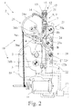
- Fig. 2
- eine Aufsicht der Kraftfahrzeugschlossanordnung aus
Fig. 1b in einer Schließstellung, - Fig. 3
- eine Aufsicht der Kraftfahrzeugschlossanordnung aus
Fig. 1b in einer Offenstellung, wobei die Sperrklinke mit dem Hauptantrieb ausgehoben ist, - Fig. 4
- eine Aufsicht der Kraftfahrzeugschlossanordnung aus
Fig. 1b in einer Offenstellung, wobei die Sperrklinke mit dem Hilfsantrieb ausgehoben ist. -
Fig. 1 zeigt eine vorschlagsgemäße Kraftfahrzeugschlossanordnung 1. Die Kraftfahrzeugschlossanordnung 1 weist ein Kraftfahrzeugschloss 2 zum Halten einer Kraftfahrzeugtür auf. Die in Rede stehende Kraftfahrzeugschlossanordnung 1 findet Anwendung bei allen Arten von Kraftfahrzeugtüren eines Kraftfahrzeugs. Der Begriff "Kraftfahrzeugtür" ist dabei weit zu verstehen. Er umfasst insbesondere Seitentüren, Hecktüren, Heckklappen, Heckdeckel oder Motorhauben. - Die Kraftfahrzeugschlossanordnung 1 weist ein erstes Schließelement 3, hier und vorzugsweise eine um eine Schlossfallenachse A schwenkbare Schlossfalle 3a, und ein als um eine Sperrklinkenachse B schwenkbare Sperrklinke 4 ausgestaltetes Schließelement 4 zum Halten des ersten Schließelements 3, 3a in mindestens einer Haltestellung auf. Im Ausführungsbeispiel weist das Kraftfahrzeugschloss 2 zwei Haltestellungen, nämlich eine Hauptschließstellung und eine Vorschließstellung, auf. Darüber hinaus weist hier und vorzugsweise die Kraftfahrzeugschlossanordnung 1 ein weiteres Schließelement, den Schließkeil 5, auf, der in üblicher Weise mit der Schlossfalle 3a zusammenwirkt.
- In einer alternativen, hier nicht gezeigten Ausgestaltung kann die Kraftfahrzeugschlossanordnung 1 auch einen Schließriegel aufweisen, welcher zum Halten einer Kraftfahrzeugtür in das Kraftfahrzeugschloss 2 eintaucht und dort von der Sperrklinke gehalten wird. Dieser kann dann ein erstes Schließelement 3 der Kraftfahrzeugschlossanordnung 1 bilden. Bezüglich dieser Ausgestaltung wird auf die auf denselben Anmelder zurückgehende deutsche Gebrauchsmusteranmeldung
DE 20 2015 104 003 verwiesen, welche insoweit zum Gegenstand dieser Anmeldung gemacht wird. - Ferner weist die vorschlagsgemäße Kraftfahrzeugschlossanordnung 1 einen Formgedächtnisantrieb 6 zum Ausheben der Sperrklinke 4 auf. Der Formgedächtnisantrieb 6 weist eine Formgedächtnisanordnung 7 mit mindestens einem Formegedächtniselement 8 zum Ausheben der Sperrklinke 4 durch eine Gestaltänderung des Formgedächtniselements 8 auf. Die
Fig. 4 zeigt die Kraftfahrzeugschlossanordnung 2 mit durch das Formgedächtniselement 8 ausgehobener Sperrklinke 4. - Hier und vorzugsweise ist der Formgedächtnisantrieb 8 als Hilfsantrieb 9 zum notfallbedingten Ausheben der Sperrklinke 4 ausgebildet. Zusätzlich kann er einen Hauptantrieb 10 zum normalbetriebsgemäßen Ausheben der Sperrklinke 4 aufweisen. Hier und vorzugsweise ist der Hauptantrieb 10 als Elektromotor 11 ausgebildet. Die
Fig. 3 zeigt die Kraftfahrzeugschlossanordnung 1 mit durch den Hauptantrieb 10 ausgehobener Sperrklinke 4. - Darüber hinaus weist die vorschlagsgemäße Kraftfahrzeugschlossanordnung 1 eine Rückstellvorrichtung 12 zur manuellen Rückstellung der das Ausheben der Sperrklinke 4 verursachenden Gestaltänderung des Formgedächtniselements 8 auf. Die Rückstellvorrichtung weist ein Rückstellelement 13 auf, über das zwecks Rückstellung des Formgedächtniselements 8 eine Rückstellkraft in das Formgedächtniselement 8 eingeleitet werden kann. Hierfür ist das Rückstellelement 8 von außerhalb des Kraftfahrzeugschlosses 2 zugänglich.
- Ein manuelles Rückstellen des Formgedächtniselements 8 von außen wird durch die vorschlagsgemäße Lösung besonders einfach ermöglicht. Ein Öffnen und/oder Demontieren von Teilen des Kraftfahrzeugschlosses 2 ist nicht erforderlich. Es ergibt sich also ein kostengünstiges und zugleich leicht rückstellbares Kraftfahrzeugschloss 2. Zudem muss auch der Formgedächtnisantrieb 6 nicht stärker ausgelegt werden, um etwaige Rückstellkräfte beim Ausheben der Sperrklinke 4 zu überwinden, wie dies etwa beim Vorsehen einer dem Formgedächtniselement 8 zugeordneten Rückstellfeder notwendig wäre. Daher ist die Rückstellvorrichtung, insbesondere der Formgedächtnisantrieb insgesamt, vorzugsweise federlos ausgebildet.
- Zusätzlich oder alternativ kann es dennoch vorgesehen sein, dass im Antriebsstrang zwischen Formgedächtnisanordnung 7 und Sperrklinke 4 Federn vorhanden sind, die in Summe eine Kraft auf die Formgedächtnisanordnung 7 in Rückstellrichtung ausüben, welche geringer ist, als die erforderliche Rückstellkraft zum Rückstellen der Formgedächtnisanordnung nach dem Abschalten desselben. Auf diese Weise kann sichergestellt werden, dass die Sperrklinke 4 beispielsweise bis zum manuellen Rückstellen ausgehoben bleibt und nicht sofort nach dem Abschalten der Formgedächtnisanordnung 7 wieder einfällt. Bei einer solchen Feder kann es sich um eine der Sperrklinke 4 zugeordnete Sperrklinkenfeder handeln. Vorzugsweise ist die Kraft, die die Sperrklinkenfeder auf die Formgedächtnisanordnung 7 ausübt, geringer, als die erforderliche Rückstellkraft zum Rückstellen der Formgedächtnisanordnung 7 nach dem Abschalten derselben.
- Interessant bei der vorschlagsgemäßen Lösung ist die Tatsache, dass sich bei einem notfallbedingten Ausheben der Sperrklinke 4 durch den Formgedächtnisantrieb 6 ein Halteeffekt ergibt, der dafür sorgt, dass die Sperrklinke 4 vom Formgedächtnisantrieb 6 permanent in ihrer ausgehobenen Stellung gehalten wird, bis die obige Rückstellung vollzogen wird. Dies insbesondere ohne weitere Bestromung des Formgedächtnisantriebs 6. Ein solcher Halteeffekt ist insbesondere bei einer Schwächung der Energieversorgung vorteilhaft, da auf ein mehrmaliges Ausheben der Sperrklinke 4 verzichtet werden kann.
- Hier und vorzugsweise ist das Rückstellelement 13 nach Art eines Schiebers, insbesondere eines Linearschiebers ausgebildet. Es wird in einer, insbesondere linearen, nicht gezeigten Führung geführt.
- Alternativ kann das Rückstellelement 13 auch nach Art eines Hebels, insbesondere eines Schwenkhebels, ausgebildet sein. Auch bei einer hebelartigen Ausbildung kann die Rückstellung des Formgedächtniselements 8 durch eine definierte Bewegung erfolgen.
- Die manuelle Rückstellbewegung kann im Wesentlichen entgegen der Aushebebewegung durch das Formgedächtniselement 8 und/oder in gleicher Richtung mit der Aushebebewegung erfolgen. Ferner kann die Rückstellbewegung im Wesentlichen senkrecht zu der Aushebebewegung durch das Formgedächtniselement 8 erfolgen. Die Rückstellbewegung ist vorzugsweise diejenige Bewegung, mittels welcher manuell von außerhalb des Kraftfahrzeugschlosses 2 die Rückstellung des Formgedächtniselements 8 erfolgt.
- Das Rückstellelement 13 weist vorzugsweise eine Angriffsfläche 14 zum Einleiten der Rückstellkraft auf. Das Kraftfahrzeugschloss 2 im Übrigen weist vorzugsweise eine Abstützfläche 15 zur Abstützung der Rückstellkraft auf. Hier und vorzugsweise weisen die Angriffsfläche 14 und die Abstützfläche 15 in entgegengesetzte Richtungen. Es ist damit leicht möglich, über die Angriffsfläche 14 und die Abstützfläche 15 die Rückstellkraft mittels eines zangenartigen Werkzeugs einzuleiten. Es ergibt sich eine insgesamt besonders einfache Rückstellung des Formgedächtniselements 8.
- Hier und vorzugsweise ist das Kraftfahrzeugschloss 2 mit einem Gehäuse 16 ausgestattet, das eine Gehäuseöffnung 17 aufweist. Vorzugsweise ist das Rückstellelement 13, insbesondere dessen Angriffsfläche 14, durch die Gehäuseöffnung 17 zugänglich. Zusätzlich oder alternativ kann das Rückstellelement 13, insbesondere seine Angriffsfläche 14, in die Gehäuseöffnung 17 ragen und/oder durch die Gehäuseöffnung hindurch ragen. Auf diese Weise kann das Innere des Kraftfahrzeugschlosses 2 durch das Gehäuse 16 geschützt werden, während das Rückstellelement 13 zur Rückstellung des Formgedächtniselements 8 leicht von außerhalb des Kraftfahrzeugschlosses 2 zugänglich ist. Vorzugsweise ist die Abstütztläche 15 am Gehäuse 16 ausgebildet. Dabei beträgt der Abstand zwischen der Abstützfläche 15 und der Angriffsfläche 14 vor der Rückstellung des Formgedächtniselements 8 vorzugsweise maximal 5 cm, weiter vorzugsweise maximal 3 cm, insbesondere maximal 2 cm.
- Um die Rückstellung mit einem Werkzeug zu erleichtern, ist am Gehäuse, insbesondere durch die Gehäuseöffnung 17, ein Angriffsraum 17a zum Angreifen und Rückstellen des Rückstellelements 8 mit einem Werkzeug vorgesehen.
- Darüber hinaus kann das Kraftfahrzeugschloss 2 ein Rückblech 18 aufweisen, das vorzugsweise aus einem Metallwerkstoff ausgebildet ist. Vorzugsweise ist das Rückblech 18 am Gehäuse 16 angeordnet oder bildet einen Teil des Gehäuses 16. Auf dem Rückblech 18 ist die Sperrklinke 4 gelagert. Darüber hinaus kann auch das erste Schließelement 3, insbesondere die Schlossfalle 3a, auf dem Rückblech 18 gelagert sein. Vorzugsweise bildet das Rückblech 18 zudem ein Einlaufmaul 19 für einen mit der Schlossfalle 3a zusammenwirkenden Schließkeil 5 aus. Zur Lagerung der Sperrklinke 4 und/oder der Schlossfalle 3a kann bzw. können ein oder mehrere Dorne 20a, 20b am Rückblech 18 angeordnet sein.
- Vorzugsweise ist das Rückstellelement 13 auf der dem Rückblech 18 gegenüberliegenden Seite des Kraftfahrzeugschlosses 2 zugänglich. Das Rückstellelement 13 kann alternativ auch auf der Seite des Rückblechs 18 zugänglich sein. Ferner kann das Rückstellelement 13 an einer Stirnseite 16a des Kraftfahrzeugschlosses 2 zugänglich sein.
- Um eine Rückstellung des Formgedächtniselements 8 auch bei in eine Kraftfahrzeugtür montiertem Kraftfahrzeugschloss 2 zu ermöglichen, ist das Rückstellelement 13 in diesem montiertem Zustand zur manuellen Rückstellung zugänglich. Vorzugsweise ist das Rückstellelement 13 bei in eine Kraftfahrzeugtür montiertem Kraftfahrzeugschloss 2 zur manuellen Rückstellung nur in geöffnetem Zustand der Kraftfahrzeugtür zugänglich. Darüber hinaus kann das Rückstellelement 13 von der Sperrklinke 4 derart entkoppelt sein, dass es das Formgedächtniselement 8 zwar rückstellen kann, dass die Sperrklinke 4 durch eine Verstellung des Rückstellelements 13 jedoch nicht ausgehoben werden kann. Dies ist unter dem Aspekt des Diebstahlschutzes vorteilhaft.
- Im dargestellten Ausführungsbeispiel und vorzugsweise weist das Rückstellelement 13 eine Umlenkführung zum Umlenken des Formgedächtniselements 8 auf. Hier ist das Formgedächtniselement 8, insbesondere U-förmig, in die Umlenkführung 21 des Rückstellelements 13 gelegt. Das Formgedächtniselement 8 ist durch das Umlegen um die Umlenkführung 21 am Rückstellelement 13 befestigt. Hierdurch lässt sich besonders einfach ein Toleranzausgleich zwischen den beiden Strängen 8a, 8b des Fonngedächtniselements sicherstellen. Alternativ kann das mindestens eine Formgedächtniselement 8 auch in anderer Form am Rückstellelement 13 befestigt sein, dies insbesondere kraft- und/oder formschlüssig.
- Vorzugsweise entspricht der Rückstellweg des Rückstellelements 13 dem Verstellweg des Rückstellelements 13 durch das Formgedächtniselement 8 beim Ausheben der Sperrklinke 4. Der Verstellweg und/oder der Rückstellweg sind vorzugsweise durch nicht gezeigte Anschläge begrenzt. Die Anschläge sind vorzugsweise am Gehäuse 16 ausgebildet, beispielsweise am Gehäusedeckel 16b.
- Hier und vorzugsweise weist das Gehäuse 16 ein obiges Rückblech 18, einen Gehäusekasten 16a sowie einen Gehäusedeckel 16b auf. Vorzugsweise ist das Rückblech 18 am Boden des Gehäusekastens 16c angeordnet. Die Anschläge können am Gehäuse 16, insbesondere am Gehäusedeckel 16b angeordnet sein.
- Im Ausführungsbeispiel und vorzugsweise erstreckt sich das Formgedächtniselement 8 parallel zum Rückblech 18. Das Kraftfahrzeugschloss 2 kann insgesamt länglich ausgebildet sein, wobei sich das Formgedächtniselement 8 dann im Wesentlichen in Längsrichtung des Kraftfahrzeugschlosses 2 erstreckt.
- Vorzugsweise schneidet das Formgedächtniselement 8 die Verbindungslinie zwischen der Rotationsachse der Schlossfalle 3a und der Rotationsachse der Sperrklinke 4. Hierdurch kann eine möglichst lange Erstreckung des Formgedächtniselements 8 im Kraftfahrzeugschloss 2 erreicht werden. Gleichzeitig ergibt sich dadurch eine kompakte Bauform.
- Hier und vorzugsweise ist der Formgedächtnisanordnung 7 eine Isolieranordnung zur Temperaturisolierung des Formgedächtniselements 8 zugeordnet. Damit wird auch bei unterschiedlichen Außentemperaturen ein reproduzierbarer Betrieb des Formgedächtnisantriebs 6 gewährleistet. Besonders bewährt hat sich eine Sol-Gel-Beschichtung des Fonngedächtniselements 8 als Isolieranordnung.
- Darüber hinaus verfügt das Kraftfahrzeugschloss 2 vorzugsweise über eine elektrische Schaltanordnung 22, die mit dem Erreichen der Aushebestellung der Sperrklinke 4 das Formgedächtniselement 8 und/oder den Hauptantrieb 10 abschaltet. Hierzu kann eine Stellung der Sperrklinke 4, insbesondere eine Haltestellung und/oder eine Freigabestellung und/oder eine Stellung der Schlossfalle 3a, insbesondere die Offenstellung und/oder Hauptschließstellung und/oder die Vorrastschließstellung, mit einem Sensor 22a bzw. 22b erfasst werden. Auf diese Art und Weise wird eine Überlastung des Fonngedächtniselements 8 vermieden. Der Sensor zum Erfassen der Sperrklinkenstellung 22a erfasst die Stellung der Sperrklinke 4 über einen Hebel 22c.
- Gemäß einer weiteren Lehre, welcher eigenständige Bedeutung zukommt, weist die Kraftfahrzeugschlossanordnung 1 eine Steueranordnung 23 auf, die auf den Betrieb des Formgedächtnisantriebs 6 hin ausgelegt ist. Die Steueranordnung 23 schaltet zum Ausheben der Sperrklinke 4 vom Hauptantrieb 10 auf einen Hilfsantrieb 9 um, wenn die in einem Energiespeicher zum elektrischen Versorgen des Hauptantriebs 10 gespeicherte Energiemenge unter einen vorbestimmten Schwellwert fällt.
- Die Kraftfahrzeugschlossanordnung 1 gemäß der weiteren Lehre kann auch alle zuvor beschriebenen Merkmale einzeln oder in Kombination aufweisen. Insofern wird auf die vorstehende Beschreibung verwiesen. Darüber hinaus können beide Kraftfahrzeugschlossanordnungen 1 alle nachfolgend beschriebenen Merkmale einzeln oder in Kombination aufweisen.
- Der Energiespeicher kann die Fahrzeugbatterie und/oder eine Batterie und/oder ein Akkumulator und/oder ein Kondensator zum Betrieb des Kraftfahrzeugschlosses 2 sein. Insofern kann der Energiespeicher ein Netzwerk von Energiespeichern, insbesondere auch unterschiedlicher Art sein. Insbesondere kann das Netzwerk von Batteriespeichern auch einen dezidiert dem Kraftfahrzeugschloss 2 zugeordneten Energiespeicher aufweisen. Vorzugsweise ist dieser am oder im Kraftfahrzeugschloss 2 angeordnet. Bei dem Energiespeicher kann es sich aber auch um einen ausschließlich dem Formgedächtnisantrieb 6 zugeordneten Energiespeicher handeln.
- Als Maß für die Energiemenge kann vorzugsweise die Versorgungsspannung herangezogen werden. Dies ermöglicht ein besonders einfaches und sicheres Bestimmen der Energiemenge bzw. der Restenergiemenge. Hier und vorzugsweise ist der Schwellwert derart gewählt, dass die noch gespeicherte Energiemenge für ein letztes sicheres Ausheben der Sperrklinke 4 ausreicht.
- Zusätzlich oder alternativ ist das Kraftfahrzeugschloss 2 vorzugsweise derart ausgebildet und eingerichtet, dass der Hilfsantrieb 9 dann zugeschaltet und ggf. der Hauptantrieb 10 abgeschaltet wird, wenn die Kraft des Hauptantriebs 10 zum Ausheben der Sperrklinke 4 nicht ausreicht.
- Weiter vorzugsweise ist mit dem Hilfsantrieb 9 eine größere Aushebekraft auf die Sperrklinke 4 aufbringbar, als mit dem Hauptantrieb 10. Hierdurch kann im Notfall auch eine höhere Aushebekraft als im Nonnalbetrieb auf die Sperrklinke 4 ausgeübt werden. Hierdurch wird ein besonders sicheres notfallbedingtes Ausheben ermöglicht. Ferner können der Hauptantrieb 10 und der Hilfsantrieb 9 derart ausgebildet sein, dass der Hauptantrieb 10 die Sperrklinke 4 schneller ausheben kann als der Hilfsantrieb 9.
- Hier und vorzugsweise ist ein Betätigungselement 24 zum Ausheben der Sperrklinke 4 vorgesehen, welches insbesondere mit der Sperrklinke 4 fest verbunden sein kann. Das Betätigungselement 24 und die Sperrklinke 4 weisen vorzugsweise eine gemeinsame Rotationsachse auf. Auf das Betätigungselement 24 wirken zum Ausheben der Sperrklinke 4 vorzugsweise sowohl der Hauptantrieb 10 als auch der Hilfsantrieb 9. Zum Ausheben der Sperrklinke 4 können der Hauptantrieb 10 und der Hilfsantrieb 9 gemeinsam auf das Betätigungselement 24 einwirken. Vorzugsweise wirkt jedoch entweder der Hauptantrieb 10 oder der Hilfsantrieb 9 auf das Betätigungselement 24 zum Ausheben der Sperrklinke 4 ein.
- Zwischen der Formgedächtnisanordnung 7 und der Sperrklinke 4 kann ein Getriebe 25 angeordnet sein. Alternativ oder zusätzlich kann zwischen dem Hauptantrieb 10 und der Sperrklinke 4 ein Hauptgetriebe 26 angeordnet sein.
- Hier und vorzugsweise ist sowohl zwischen der Formgedächtnisanordnung 7 und der Sperrklinke 4 ein Getriebe 25 als auch zwischen dem Hauptantrieb 10 und der Sperrklinke 4 ein Hauptgetriebe 26 angeordnet. Im Ausführungsbeispiel weisen die beiden Getriebe 25, 26 ein gemeinsames Abtriebsgetriebeelement auf. Hier und vorzugsweise ist wie hier das Betätigungselement 24 als gemeinsames Abtriebsgetriebeelement ausgebildet.
- Der Antriebsstrang des Hauptantriebs 10 weist ein flexibles Zugmittel 26a, insbesondere ein Seil auf, über das die Antriebskraft auf eine Kulisse 26b übertragen wird. Hierzu wird das flexible Zugmittel 26a vorzugsweise direkt auf eine Welle, insbesondere die Motorwelle des Elektromotors 11 aufgewickelt. Von der Kulisse 26b wird die Antriebskraft über einen dem Betätigungselement 24 zuzuordnenden Hebel 24a, welcher insbesondere als Draht ausgebildet sein kann, auf das Betätigungselement 24 und damit die Sperrklinke 4 übertragen (
Fig. 3 ). - Die Kulisse 26b und der Hebel 24a sind unidirektional miteinander gekoppelt. Durch die unidirektionale Kopplung wird die Entkopplung des Hauptantriebs 10 beim Ausheben der Sperrklinke 4 mit dem Hilfsantrieb 9 hergestellt.
- Der Antriebsstrang des Hilfsantriebs 9 bzw. Formgedächtnisantriebs 6 überträgt die Antriebskraft vom Rückstellelement 13 über einen Hebel 25a auf das Betätigungselement 24. Der Hebel 25a und das Betätigungselement sind unidirektional miteinander gekoppelt. Durch die unidirektionale Kopplung wird die Entkopplung des Hilfsantriebs 9 beim Ausheben der Sperrklinke 4 mit dem Hauptantrieb 10 hergestellt.
- Das Betätigungselement 24 und die Sperrklinke 4 sind bevorzugt über einen Draht, insbesondere den den Hebel 24a bildenden Draht, fest miteinander verbunden.
- Das Rückstellelement 13 und das Hauptgetriebe 25 befinden sich in unterschiedlichen Ebenen des Kraftfahrzeugschlosses 2. Weiter vorzugsweise liegen die Schließelemente 3, 3a, 4 in einer weiteren Ebene des Kraftfahrzeugschlosses 2. Hier liegen die Schließelemente 3, 3a, 4 in einer Ebene direkt auf dem Rückblech 18. In einer darüber angeordneten Ebene ist das Hauptgetriebe 25 angeordnet. In einer darüber angeordneten Ebene ist die Formgedächtnisanordnung angeordnet. Das Getriebe 25 von der Formgedächtnisanordnung zur Sperrklinke befindet sich zumindest teilweise in der Ebene des Hauptgetriebes 25.
Claims (15)
- Kraftfahrzeugschlossanordnung mit einem Kraftfahrzeugschloss (2), wobei die Kraftfahrzeugschlossanordnung (1) ein erstes Schließelement (3, 3a), insbesondere eine Schlossfalle (3a), und ein als Sperrklinke (4) ausgestaltetes Schließelement zum Halten des ersten Schließelements (3, 3a) in mindestens einer Haltestellung sowie einen Formgedächtnisantrieb (6) zum Ausheben der Sperrklinke (4) aufweist, wobei der Formgedächtnisantrieb (6) eine Formgedächtnisanordnung (7) mit mindestens einem Formgedächtniselement (8) zum Ausheben der Sperrklinke (4) durch eine Gestaltänderung des Formgedächtniselements (8) umfasst, wobei eine Rückstellvorrichtung (12) zur manuellen Rückstellung der das Ausheben der Sperrklinke (4) verursachenden Gestaltänderung des Formgedächtniselements (8) vorgesehen ist,
dadurch gekennzeichnet,
dass die Rückstellvorrichtung (12) ein Rückstellelement (13) aufweist, über das für die manuelle Rückstellung des Formgedächtniselements (8) eine Rückstellkraft in das Formgedächtniselement (8) einleitbar ist und dass das Rückstellelement (8) hierfür von außerhalb des Kraftfahrzeugschlosses (2) zugänglich ist. - Kraftfahrzeugschlossanordnung nach Anspruch 1, dadurch gekennzeichnet, dass das Rückstellelement (13) nach Art eines Schiebers und/oder nach Art eines Hebels ausgebildet ist.
- Kraftfahrzeugschlossanordnung nach Anspruch 1 oder 2, dadurch gekennzeichnet, dass das Rückstellelement (13) eine Angriffsfläche (14) zum Einleiten der Rückstellkraft aufweist und das Kraftfahrzeugschloss (2) im Übrigen eine Abstützfläche (15) zur Abstützung der Rückstellkraft aufweist, vorzugsweise, dass die Angriffsfläche (14) und die Abstützfläche (15) in entgegengesetzte Richtungen weisen, weiter vorzugsweise, dass über die Angriffsfläche (14) und die Abstützfläche (15) die Rückstellkraft mittels eines zangenartigen Werkzeugs einleitbar ist.
- Kraftfahrzeugschlossanordnung nach einem der vorhergehenden Ansprüche, dadurch gekennzeichnet, dass das Kraftfahrzeugschloss (2) ein Gehäuse (16) mit einer Gehäuseöffnung (17) aufweist und das Rückstellelement (13), insbesondere die Angriffsfläche (14), durch die Gehäuseöffnung (17) zugänglich ist und/oder in die Gehäuseöffnung (17) ragt und/oder durch die Gehäuseöffnung (17) hindurch ragt.
- Kraftfahrzeugschlossanordnung nach einem der vorhergehenden Ansprüche, dadurch gekennzeichnet, dass das Kraftfahrzeugschloss (2) ein Rückblech (18) aufweist, auf dem die Sperrklinke (4) gelagert ist, vorzugsweise das Rückstellelement (13) auf der dem Rückblech (18) gegenüberliegenden Seite des Kraftfahrzeugschlosses (2) zugänglich ist.
- Kraftfahrzeugschlossanordnung nach einem der vorhergehenden Ansprüche, dadurch gekennzeichnet, dass das Rückstellelement (13) bei in eine Kraftfahrzeugtür montiertem Kraftfahrzeugschloss (2) zur manuellen Rückstellung zugänglich ist.
- Kraftfahrzeugschlossanordnung nach einem der vorhergehenden Ansprüche, dadurch gekennzeichnet, dass das Rückstellelement (13) eine Umlenkführung (21) zum Umlenken des Formgedächtniselements (8) aufweist, vorzugsweise, dass das Formgedächtniselement (8), insbesondere U-förmig, um die Umlenkführung (21) des Rückstellelements (13) gelegt ist.
- Kraftfahrzeugschlossanordnung nach einem der Ansprüche 5 bis 7, dadurch gekennzeichnet, dass sich das Formgedächtniselement (8) parallel zum Rückblech (18) erstreckt.
- Kraftfahrzeugschlossanordnung nach einem der vorhergehenden Ansprüche, dadurch gekennzeichnet, dass die Formgedächtnisanordnung (7) eine Isolieranordnung zur Temperaturisolierung des Formgedächtniselements (8) umfasst, vorzugsweise, dass die Isolieranordnung eine Sol-Gel-Beschichtung ist.
- Kraftfahrzeugschlossanordnung nach einem der vorhergehenden Ansprüche, dadurch gekennzeichnet, dass die Kraftfahrzeugschlossanordnung (1) einen Hauptantrieb (10) zum normalbetriebsgemäßen Ausheben der Sperrklinke (4) aufweist und dass der Formgedächtnisantrieb (6) als Hilfsantrieb (9) zum notfallbedingten Ausheben der Sperrklinke (4) dient, vorzugsweise, dass der Hauptantrieb (10) ein Elektromotor (11) ist.
- Kraftfahrzeugschlossanordnung nach einem der vorhergehenden Ansprüche, dadurch gekennzeichnet, dass das Kraftfahrzeugschloss (2) eine elektrische Schaltanordnung (22) aufweist, die mit dem Erreichen einer Aushebestellung der Sperrklinke (4) den Formgedächtnisantrieb (6), insbesondere das Formgedächtniselement (8), und/oder den Hauptantrieb abschaltet.
- Kraftfahrzeugschlossanordnung nach Anspruch 11, dadurch gekennzeichnet, dass mit dem Hilfsantrieb (9) eine größere Aushebekraft auf die Sperrklinke (4) aufbringbar ist als mit dem Hauptantrieb (10).
- Kraftfahrzeugschlossanordnung mit einem Kraftfahrzeugschloss (2), wobei die Kraftfahrzeugschlossanordnung (1) ein erstes Schließelement (3, 3a), insbesondere eine Schlossfalle (3a), und ein als Sperrklinke (4) ausgestaltetes Schließelement zum Halten des ersten Schließelements (3, 3a) in mindestens einer Haltestellung sowie einen Formgedächtnisantrieb (6) zum Ausheben der Sperrklinke (4) aufweist, wobei der Formgedächtnisantrieb (6) eine Formgedächtnisanordnung (7) mit mindestens einem Formgedächtniselement (8) zum Ausheben der Sperrklinke (4) durch eine Gestaltänderung des Formgedächtniselements (8) umfasst, wobei die Kraftfahrzeugschlossanordnung (1) einen Hauptantrieb (10), insbesondere einen Elektromotor (11), zum normalbetriebsgemäßen Ausheben der Sperrklinke (4) aufweist und der Formgedächtnisantrieb (6) als Hilfsantrieb (9) zum notfallbedingten Ausheben der Sperrklinke (4) dient,
dadurch gekennzeichnet,
dass die Kraftfahrzeugschlossanordnung (1) eine Steueranordnung (23) aufweist, welche zum Ausheben der Sperrklinke (4) vom Hauptantrieb (10) auf einen Hilfsantrieb (9) umschaltet, wenn die in einem Energiespeicher zum elektrischen Versorgen des Hauptantriebs (10) gespeicherte Energiemenge unter einen vorbestimmten Schwellwert fällt. - Kraftfahrzeugschlossanordnung nach Anspruch 13, dadurch gekennzeichnet, dass als Maß für die Energiemenge die Versorgungsspannung herangezogen wird.
- Kraftfahrzeugschlossanordnung nach Anspruch 13 oder 14, gekennzeichnet durch das Kennzeichen eines der vorhergehenden Ansprüche.
Applications Claiming Priority (1)
| Application Number | Priority Date | Filing Date | Title |
|---|---|---|---|
| DE202015104678.2U DE202015104678U1 (de) | 2015-09-03 | 2015-09-03 | Kraftfahrzeugschloss |
Publications (3)
| Publication Number | Publication Date |
|---|---|
| EP3147433A2 true EP3147433A2 (de) | 2017-03-29 |
| EP3147433A3 EP3147433A3 (de) | 2017-08-09 |
| EP3147433B1 EP3147433B1 (de) | 2020-05-27 |
Family
ID=56883565
Family Applications (1)
| Application Number | Title | Priority Date | Filing Date |
|---|---|---|---|
| EP16186317.0A Active EP3147433B1 (de) | 2015-09-03 | 2016-08-30 | Kraftfahrzeugschloss |
Country Status (2)
| Country | Link |
|---|---|
| EP (1) | EP3147433B1 (de) |
| DE (1) | DE202015104678U1 (de) |
Cited By (3)
| Publication number | Priority date | Publication date | Assignee | Title |
|---|---|---|---|---|
| EP3412853A1 (de) * | 2017-06-09 | 2018-12-12 | Brose Schliesssysteme GmbH & Co. KG | Kraftfahrzeugschloss |
| US20200115930A1 (en) * | 2018-10-11 | 2020-04-16 | Volkswagen Aktiengesellschaft | Method for operating an opening mechanism |
| GB2604645A (en) * | 2021-03-12 | 2022-09-14 | Jaguar Land Rover Ltd | Vehicle side door latch apparatus comprising a pulley-connected electrical release actuator |
Families Citing this family (2)
| Publication number | Priority date | Publication date | Assignee | Title |
|---|---|---|---|---|
| DE102018120447A1 (de) * | 2018-08-22 | 2020-02-27 | Kiekert Ag | Verfahren zur Steuerung eines Kraftfahrzeugschlosses |
| DE102019115273A1 (de) * | 2019-06-06 | 2020-12-10 | Kiekert Aktiengesellschaft | Kraftfahrzeugschloss |
Citations (1)
| Publication number | Priority date | Publication date | Assignee | Title |
|---|---|---|---|---|
| DE202013007862U1 (de) | 2013-09-05 | 2014-12-08 | BROSE SCHLIEßSYSTEME GMBH & CO. KG | Kraftfahrzeugschloss |
Family Cites Families (7)
| Publication number | Priority date | Publication date | Assignee | Title |
|---|---|---|---|---|
| DE3005470A1 (de) * | 1980-01-14 | 1981-07-23 | BBC AG Brown, Boveri & Cie., Baden, Aargau | Thermomechanischer schutzschalter |
| DE10251382A1 (de) * | 2002-11-01 | 2004-05-13 | Siemens Ag | Verfahren zur Betätigung einer Sperrklinke in einem Schloss mit Drehfalle für ein Kraftfahrzeug |
| US8505987B2 (en) * | 2009-03-17 | 2013-08-13 | GM Global Technology Operations LLC | Electrically-activated hood latch and release mechanism |
| US8974641B2 (en) * | 2011-01-24 | 2015-03-10 | Carefusion 303, Inc. | Self-adjusting preload for memory alloy wire |
| DE102013111039A1 (de) * | 2013-10-04 | 2015-04-09 | BROSE SCHLIEßSYSTEME GMBH & CO. KG | Antriebsanordnung für ein Kraftfahrzeugschloss |
| US20160130843A1 (en) * | 2014-11-12 | 2016-05-12 | Adac Plastics, Inc. | Low voltage backup assembly for electronic latch |
| DE202015104003U1 (de) | 2015-07-31 | 2016-11-03 | BROSE SCHLIEßSYSTEME GMBH & CO. KG | Kraftfahrzeugschlossanordnung |
-
2015
- 2015-09-03 DE DE202015104678.2U patent/DE202015104678U1/de not_active Expired - Lifetime
-
2016
- 2016-08-30 EP EP16186317.0A patent/EP3147433B1/de active Active
Patent Citations (1)
| Publication number | Priority date | Publication date | Assignee | Title |
|---|---|---|---|---|
| DE202013007862U1 (de) | 2013-09-05 | 2014-12-08 | BROSE SCHLIEßSYSTEME GMBH & CO. KG | Kraftfahrzeugschloss |
Cited By (5)
| Publication number | Priority date | Publication date | Assignee | Title |
|---|---|---|---|---|
| EP3412853A1 (de) * | 2017-06-09 | 2018-12-12 | Brose Schliesssysteme GmbH & Co. KG | Kraftfahrzeugschloss |
| US20200115930A1 (en) * | 2018-10-11 | 2020-04-16 | Volkswagen Aktiengesellschaft | Method for operating an opening mechanism |
| US11725427B2 (en) * | 2018-10-11 | 2023-08-15 | Volkswagen Aktiengesellschaft | Method for operating an opening mechanism |
| GB2604645A (en) * | 2021-03-12 | 2022-09-14 | Jaguar Land Rover Ltd | Vehicle side door latch apparatus comprising a pulley-connected electrical release actuator |
| GB2604645B (en) * | 2021-03-12 | 2024-07-31 | Jaguar Land Rover Ltd | Vehicle side door latch apparatus comprising a pulley-connected electrical release actuator |
Also Published As
| Publication number | Publication date |
|---|---|
| EP3147433B1 (de) | 2020-05-27 |
| EP3147433A3 (de) | 2017-08-09 |
| DE202015104678U1 (de) | 2016-12-06 |
Similar Documents
| Publication | Publication Date | Title |
|---|---|---|
| EP2342405B1 (de) | Kraftfahrzeugschloss | |
| EP3612697B1 (de) | Schloss für ein kraftfahrzeug | |
| EP2326781B1 (de) | Schlosseinheit mit mehrteiliger sperrklinke und federvorgespannter blockierklinke | |
| DE60010606T2 (de) | Verschluss | |
| EP3147433B1 (de) | Kraftfahrzeugschloss | |
| DE102008018500A1 (de) | Kraftfahrzeugschloß | |
| EP3284885A1 (de) | Kraftfahrzeugschlossanordnung | |
| EP2291571A1 (de) | Schliessvorrichtung mit sperrklinkenfeder | |
| WO2021151422A1 (de) | Aufstellvorrichtung für eine kraftfahrzeugtür | |
| EP4386158A1 (de) | Türöffner | |
| DE102017216920A1 (de) | Türgriffeinrichtung für eine Tür eines Kraftfahrzeugs, Tür, Kraftfahrzeug | |
| EP2987931B1 (de) | Kraftfahrzeugschloss | |
| EP0481503A1 (de) | Türverriegelung für einen Haushaltsgerät | |
| DE202013101929U1 (de) | Zugentlastungsgehäuse | |
| DE102012014596A1 (de) | Kraftfahrzeugschloss | |
| DE102009050077A1 (de) | Fahrzeugschloss | |
| DE102013212508B4 (de) | Türanlage | |
| DE102011054684A1 (de) | Schloss | |
| WO2016134698A1 (de) | Kraftfahrzeugschloss | |
| DE19847079A1 (de) | Elektrisches Schloß für Kraftfahrzeuge | |
| DE102013212514A1 (de) | Türanlage | |
| WO2008015026A1 (de) | Türmodul mit fensterhebereinrichtung | |
| EP0942123A1 (de) | Vorrichtung zum Verriegeln einer Abdeckung nach Art einer Karosseriehaube eines Kraftfahrzeugs | |
| EP3269902B1 (de) | Betätigungsanordnung für einen gebäudeverschluss, entsprechender gebäudeverschluss, montagesatz zur herstellung von gebäudeverschlüssen sowie verfahren zum ausrüsten eines gebäudeverschlusses | |
| WO2020212070A1 (de) | Flügelelementöffnungsvorrichtung sowie fahrzeug |
Legal Events
| Date | Code | Title | Description |
|---|---|---|---|
| PUAI | Public reference made under article 153(3) epc to a published international application that has entered the european phase |
Free format text: ORIGINAL CODE: 0009012 |
|
| STAA | Information on the status of an ep patent application or granted ep patent |
Free format text: STATUS: THE APPLICATION HAS BEEN PUBLISHED |
|
| AK | Designated contracting states |
Kind code of ref document: A2 Designated state(s): AL AT BE BG CH CY CZ DE DK EE ES FI FR GB GR HR HU IE IS IT LI LT LU LV MC MK MT NL NO PL PT RO RS SE SI SK SM TR |
|
| AX | Request for extension of the european patent |
Extension state: BA ME |
|
| PUAL | Search report despatched |
Free format text: ORIGINAL CODE: 0009013 |
|
| AK | Designated contracting states |
Kind code of ref document: A3 Designated state(s): AL AT BE BG CH CY CZ DE DK EE ES FI FR GB GR HR HU IE IS IT LI LT LU LV MC MK MT NL NO PL PT RO RS SE SI SK SM TR |
|
| AX | Request for extension of the european patent |
Extension state: BA ME |
|
| RIC1 | Information provided on ipc code assigned before grant |
Ipc: E05B 81/14 20140101ALN20170704BHEP Ipc: E05B 81/66 20140101ALN20170704BHEP Ipc: E05B 81/42 20140101ALN20170704BHEP Ipc: E05B 81/80 20140101ALN20170704BHEP Ipc: E05B 51/00 20060101ALI20170704BHEP Ipc: E05B 81/90 20140101ALN20170704BHEP Ipc: E05B 81/64 20140101ALN20170704BHEP Ipc: E05B 81/06 20140101ALN20170704BHEP Ipc: E05B 47/00 20060101AFI20170704BHEP |
|
| STAA | Information on the status of an ep patent application or granted ep patent |
Free format text: STATUS: REQUEST FOR EXAMINATION WAS MADE |
|
| 17P | Request for examination filed |
Effective date: 20180209 |
|
| RBV | Designated contracting states (corrected) |
Designated state(s): AL AT BE BG CH CY CZ DE DK EE ES FI FR GB GR HR HU IE IS IT LI LT LU LV MC MK MT NL NO PL PT RO RS SE SI SK SM TR |
|
| RIC1 | Information provided on ipc code assigned before grant |
Ipc: E05B 81/06 20140101ALN20191204BHEP Ipc: E05B 47/00 20060101AFI20191204BHEP Ipc: E05B 81/42 20140101ALN20191204BHEP Ipc: E05B 81/64 20140101ALN20191204BHEP Ipc: E05B 81/90 20140101ALN20191204BHEP Ipc: E05B 81/66 20140101ALN20191204BHEP Ipc: E05B 51/00 20060101ALI20191204BHEP Ipc: E05B 81/80 20140101ALN20191204BHEP Ipc: E05B 81/14 20140101ALN20191204BHEP |
|
| GRAP | Despatch of communication of intention to grant a patent |
Free format text: ORIGINAL CODE: EPIDOSNIGR1 |
|
| STAA | Information on the status of an ep patent application or granted ep patent |
Free format text: STATUS: GRANT OF PATENT IS INTENDED |
|
| INTG | Intention to grant announced |
Effective date: 20200113 |
|
| GRAS | Grant fee paid |
Free format text: ORIGINAL CODE: EPIDOSNIGR3 |
|
| GRAA | (expected) grant |
Free format text: ORIGINAL CODE: 0009210 |
|
| STAA | Information on the status of an ep patent application or granted ep patent |
Free format text: STATUS: THE PATENT HAS BEEN GRANTED |
|
| AK | Designated contracting states |
Kind code of ref document: B1 Designated state(s): AL AT BE BG CH CY CZ DE DK EE ES FI FR GB GR HR HU IE IS IT LI LT LU LV MC MK MT NL NO PL PT RO RS SE SI SK SM TR |
|
| REG | Reference to a national code |
Ref country code: GB Ref legal event code: FG4D Free format text: NOT ENGLISH |
|
| REG | Reference to a national code |
Ref country code: CH Ref legal event code: EP |
|
| REG | Reference to a national code |
Ref country code: DE Ref legal event code: R096 Ref document number: 502016010035 Country of ref document: DE |
|
| REG | Reference to a national code |
Ref country code: AT Ref legal event code: REF Ref document number: 1274703 Country of ref document: AT Kind code of ref document: T Effective date: 20200615 |
|
| REG | Reference to a national code |
Ref country code: LT Ref legal event code: MG4D |
|
| PG25 | Lapsed in a contracting state [announced via postgrant information from national office to epo] |
Ref country code: LT Free format text: LAPSE BECAUSE OF FAILURE TO SUBMIT A TRANSLATION OF THE DESCRIPTION OR TO PAY THE FEE WITHIN THE PRESCRIBED TIME-LIMIT Effective date: 20200527 Ref country code: GR Free format text: LAPSE BECAUSE OF FAILURE TO SUBMIT A TRANSLATION OF THE DESCRIPTION OR TO PAY THE FEE WITHIN THE PRESCRIBED TIME-LIMIT Effective date: 20200828 Ref country code: SE Free format text: LAPSE BECAUSE OF FAILURE TO SUBMIT A TRANSLATION OF THE DESCRIPTION OR TO PAY THE FEE WITHIN THE PRESCRIBED TIME-LIMIT Effective date: 20200527 Ref country code: NO Free format text: LAPSE BECAUSE OF FAILURE TO SUBMIT A TRANSLATION OF THE DESCRIPTION OR TO PAY THE FEE WITHIN THE PRESCRIBED TIME-LIMIT Effective date: 20200827 Ref country code: FI Free format text: LAPSE BECAUSE OF FAILURE TO SUBMIT A TRANSLATION OF THE DESCRIPTION OR TO PAY THE FEE WITHIN THE PRESCRIBED TIME-LIMIT Effective date: 20200527 Ref country code: PT Free format text: LAPSE BECAUSE OF FAILURE TO SUBMIT A TRANSLATION OF THE DESCRIPTION OR TO PAY THE FEE WITHIN THE PRESCRIBED TIME-LIMIT Effective date: 20200928 Ref country code: IS Free format text: LAPSE BECAUSE OF FAILURE TO SUBMIT A TRANSLATION OF THE DESCRIPTION OR TO PAY THE FEE WITHIN THE PRESCRIBED TIME-LIMIT Effective date: 20200927 |
|
| REG | Reference to a national code |
Ref country code: NL Ref legal event code: MP Effective date: 20200527 |
|
| PG25 | Lapsed in a contracting state [announced via postgrant information from national office to epo] |
Ref country code: RS Free format text: LAPSE BECAUSE OF FAILURE TO SUBMIT A TRANSLATION OF THE DESCRIPTION OR TO PAY THE FEE WITHIN THE PRESCRIBED TIME-LIMIT Effective date: 20200527 Ref country code: HR Free format text: LAPSE BECAUSE OF FAILURE TO SUBMIT A TRANSLATION OF THE DESCRIPTION OR TO PAY THE FEE WITHIN THE PRESCRIBED TIME-LIMIT Effective date: 20200527 Ref country code: LV Free format text: LAPSE BECAUSE OF FAILURE TO SUBMIT A TRANSLATION OF THE DESCRIPTION OR TO PAY THE FEE WITHIN THE PRESCRIBED TIME-LIMIT Effective date: 20200527 Ref country code: BG Free format text: LAPSE BECAUSE OF FAILURE TO SUBMIT A TRANSLATION OF THE DESCRIPTION OR TO PAY THE FEE WITHIN THE PRESCRIBED TIME-LIMIT Effective date: 20200827 |
|
| PG25 | Lapsed in a contracting state [announced via postgrant information from national office to epo] |
Ref country code: NL Free format text: LAPSE BECAUSE OF FAILURE TO SUBMIT A TRANSLATION OF THE DESCRIPTION OR TO PAY THE FEE WITHIN THE PRESCRIBED TIME-LIMIT Effective date: 20200527 Ref country code: AL Free format text: LAPSE BECAUSE OF FAILURE TO SUBMIT A TRANSLATION OF THE DESCRIPTION OR TO PAY THE FEE WITHIN THE PRESCRIBED TIME-LIMIT Effective date: 20200527 |
|
| PG25 | Lapsed in a contracting state [announced via postgrant information from national office to epo] |
Ref country code: RO Free format text: LAPSE BECAUSE OF FAILURE TO SUBMIT A TRANSLATION OF THE DESCRIPTION OR TO PAY THE FEE WITHIN THE PRESCRIBED TIME-LIMIT Effective date: 20200527 Ref country code: DK Free format text: LAPSE BECAUSE OF FAILURE TO SUBMIT A TRANSLATION OF THE DESCRIPTION OR TO PAY THE FEE WITHIN THE PRESCRIBED TIME-LIMIT Effective date: 20200527 Ref country code: IT Free format text: LAPSE BECAUSE OF FAILURE TO SUBMIT A TRANSLATION OF THE DESCRIPTION OR TO PAY THE FEE WITHIN THE PRESCRIBED TIME-LIMIT Effective date: 20200527 Ref country code: SM Free format text: LAPSE BECAUSE OF FAILURE TO SUBMIT A TRANSLATION OF THE DESCRIPTION OR TO PAY THE FEE WITHIN THE PRESCRIBED TIME-LIMIT Effective date: 20200527 Ref country code: EE Free format text: LAPSE BECAUSE OF FAILURE TO SUBMIT A TRANSLATION OF THE DESCRIPTION OR TO PAY THE FEE WITHIN THE PRESCRIBED TIME-LIMIT Effective date: 20200527 Ref country code: ES Free format text: LAPSE BECAUSE OF FAILURE TO SUBMIT A TRANSLATION OF THE DESCRIPTION OR TO PAY THE FEE WITHIN THE PRESCRIBED TIME-LIMIT Effective date: 20200527 |
|
| PG25 | Lapsed in a contracting state [announced via postgrant information from national office to epo] |
Ref country code: SK Free format text: LAPSE BECAUSE OF FAILURE TO SUBMIT A TRANSLATION OF THE DESCRIPTION OR TO PAY THE FEE WITHIN THE PRESCRIBED TIME-LIMIT Effective date: 20200527 Ref country code: PL Free format text: LAPSE BECAUSE OF FAILURE TO SUBMIT A TRANSLATION OF THE DESCRIPTION OR TO PAY THE FEE WITHIN THE PRESCRIBED TIME-LIMIT Effective date: 20200527 |
|
| REG | Reference to a national code |
Ref country code: DE Ref legal event code: R097 Ref document number: 502016010035 Country of ref document: DE |
|
| PG25 | Lapsed in a contracting state [announced via postgrant information from national office to epo] |
Ref country code: MC Free format text: LAPSE BECAUSE OF FAILURE TO SUBMIT A TRANSLATION OF THE DESCRIPTION OR TO PAY THE FEE WITHIN THE PRESCRIBED TIME-LIMIT Effective date: 20200527 |
|
| REG | Reference to a national code |
Ref country code: CH Ref legal event code: PL |
|
| PLBE | No opposition filed within time limit |
Free format text: ORIGINAL CODE: 0009261 |
|
| STAA | Information on the status of an ep patent application or granted ep patent |
Free format text: STATUS: NO OPPOSITION FILED WITHIN TIME LIMIT |
|
| PG25 | Lapsed in a contracting state [announced via postgrant information from national office to epo] |
Ref country code: CH Free format text: LAPSE BECAUSE OF NON-PAYMENT OF DUE FEES Effective date: 20200831 Ref country code: LI Free format text: LAPSE BECAUSE OF NON-PAYMENT OF DUE FEES Effective date: 20200831 Ref country code: LU Free format text: LAPSE BECAUSE OF NON-PAYMENT OF DUE FEES Effective date: 20200830 |
|
| 26N | No opposition filed |
Effective date: 20210302 |
|
| REG | Reference to a national code |
Ref country code: BE Ref legal event code: MM Effective date: 20200831 |
|
| PG25 | Lapsed in a contracting state [announced via postgrant information from national office to epo] |
Ref country code: SI Free format text: LAPSE BECAUSE OF FAILURE TO SUBMIT A TRANSLATION OF THE DESCRIPTION OR TO PAY THE FEE WITHIN THE PRESCRIBED TIME-LIMIT Effective date: 20200527 |
|
| PG25 | Lapsed in a contracting state [announced via postgrant information from national office to epo] |
Ref country code: IE Free format text: LAPSE BECAUSE OF NON-PAYMENT OF DUE FEES Effective date: 20200830 Ref country code: BE Free format text: LAPSE BECAUSE OF NON-PAYMENT OF DUE FEES Effective date: 20200831 |
|
| PG25 | Lapsed in a contracting state [announced via postgrant information from national office to epo] |
Ref country code: TR Free format text: LAPSE BECAUSE OF FAILURE TO SUBMIT A TRANSLATION OF THE DESCRIPTION OR TO PAY THE FEE WITHIN THE PRESCRIBED TIME-LIMIT Effective date: 20200527 Ref country code: MT Free format text: LAPSE BECAUSE OF FAILURE TO SUBMIT A TRANSLATION OF THE DESCRIPTION OR TO PAY THE FEE WITHIN THE PRESCRIBED TIME-LIMIT Effective date: 20200527 Ref country code: CY Free format text: LAPSE BECAUSE OF FAILURE TO SUBMIT A TRANSLATION OF THE DESCRIPTION OR TO PAY THE FEE WITHIN THE PRESCRIBED TIME-LIMIT Effective date: 20200527 |
|
| PG25 | Lapsed in a contracting state [announced via postgrant information from national office to epo] |
Ref country code: MK Free format text: LAPSE BECAUSE OF FAILURE TO SUBMIT A TRANSLATION OF THE DESCRIPTION OR TO PAY THE FEE WITHIN THE PRESCRIBED TIME-LIMIT Effective date: 20200527 |
|
| REG | Reference to a national code |
Ref country code: AT Ref legal event code: MM01 Ref document number: 1274703 Country of ref document: AT Kind code of ref document: T Effective date: 20210830 |
|
| PG25 | Lapsed in a contracting state [announced via postgrant information from national office to epo] |
Ref country code: AT Free format text: LAPSE BECAUSE OF NON-PAYMENT OF DUE FEES Effective date: 20210830 |
|
| P01 | Opt-out of the competence of the unified patent court (upc) registered |
Effective date: 20230803 |
|
| PGFP | Annual fee paid to national office [announced via postgrant information from national office to epo] |
Ref country code: DE Payment date: 20230831 Year of fee payment: 8 |
|
| PGFP | Annual fee paid to national office [announced via postgrant information from national office to epo] |
Ref country code: GB Payment date: 20240701 Year of fee payment: 9 |
|
| PGFP | Annual fee paid to national office [announced via postgrant information from national office to epo] |
Ref country code: FR Payment date: 20240702 Year of fee payment: 9 |
|
| PGFP | Annual fee paid to national office [announced via postgrant information from national office to epo] |
Ref country code: CZ Payment date: 20240819 Year of fee payment: 9 |
|
| REG | Reference to a national code |
Ref country code: DE Ref legal event code: R119 Ref document number: 502016010035 Country of ref document: DE |
|
| PG25 | Lapsed in a contracting state [announced via postgrant information from national office to epo] |
Ref country code: DE Free format text: LAPSE BECAUSE OF NON-PAYMENT OF DUE FEES Effective date: 20250301 |