EP3147499A1 - Pale de rotor a profil optimise contre le bruit et procede de fabrication d'une pale de rotor - Google Patents
Pale de rotor a profil optimise contre le bruit et procede de fabrication d'une pale de rotor Download PDFInfo
- Publication number
- EP3147499A1 EP3147499A1 EP16187323.7A EP16187323A EP3147499A1 EP 3147499 A1 EP3147499 A1 EP 3147499A1 EP 16187323 A EP16187323 A EP 16187323A EP 3147499 A1 EP3147499 A1 EP 3147499A1
- Authority
- EP
- European Patent Office
- Prior art keywords
- rotor blade
- profile
- trailing edge
- optimized
- rotor
- Prior art date
- Legal status (The legal status is an assumption and is not a legal conclusion. Google has not performed a legal analysis and makes no representation as to the accuracy of the status listed.)
- Granted
Links
Images




Classifications
-
- F—MECHANICAL ENGINEERING; LIGHTING; HEATING; WEAPONS; BLASTING
- F03—MACHINES OR ENGINES FOR LIQUIDS; WIND, SPRING, OR WEIGHT MOTORS; PRODUCING MECHANICAL POWER OR A REACTIVE PROPULSIVE THRUST, NOT OTHERWISE PROVIDED FOR
- F03D—WIND MOTORS
- F03D1/00—Wind motors with rotation axis substantially parallel to the air flow entering the rotor
- F03D1/06—Rotors
- F03D1/0608—Rotors characterised by their aerodynamic shape
- F03D1/0633—Rotors characterised by their aerodynamic shape of the blades
-
- F—MECHANICAL ENGINEERING; LIGHTING; HEATING; WEAPONS; BLASTING
- F05—INDEXING SCHEMES RELATING TO ENGINES OR PUMPS IN VARIOUS SUBCLASSES OF CLASSES F01-F04
- F05B—INDEXING SCHEME RELATING TO WIND, SPRING, WEIGHT, INERTIA OR LIKE MOTORS, TO MACHINES OR ENGINES FOR LIQUIDS COVERED BY SUBCLASSES F03B, F03D AND F03G
- F05B2240/00—Components
- F05B2240/20—Rotors
- F05B2240/30—Characteristics of rotor blades, i.e. of any element transforming dynamic fluid energy to or from rotational energy and being attached to a rotor
-
- F—MECHANICAL ENGINEERING; LIGHTING; HEATING; WEAPONS; BLASTING
- F05—INDEXING SCHEMES RELATING TO ENGINES OR PUMPS IN VARIOUS SUBCLASSES OF CLASSES F01-F04
- F05B—INDEXING SCHEME RELATING TO WIND, SPRING, WEIGHT, INERTIA OR LIKE MOTORS, TO MACHINES OR ENGINES FOR LIQUIDS COVERED BY SUBCLASSES F03B, F03D AND F03G
- F05B2260/00—Function
- F05B2260/96—Preventing, counteracting or reducing vibration or noise
-
- Y—GENERAL TAGGING OF NEW TECHNOLOGICAL DEVELOPMENTS; GENERAL TAGGING OF CROSS-SECTIONAL TECHNOLOGIES SPANNING OVER SEVERAL SECTIONS OF THE IPC; TECHNICAL SUBJECTS COVERED BY FORMER USPC CROSS-REFERENCE ART COLLECTIONS [XRACs] AND DIGESTS
- Y02—TECHNOLOGIES OR APPLICATIONS FOR MITIGATION OR ADAPTATION AGAINST CLIMATE CHANGE
- Y02E—REDUCTION OF GREENHOUSE GAS [GHG] EMISSIONS, RELATED TO ENERGY GENERATION, TRANSMISSION OR DISTRIBUTION
- Y02E10/00—Energy generation through renewable energy sources
- Y02E10/70—Wind energy
- Y02E10/72—Wind turbines with rotation axis in wind direction
-
- Y—GENERAL TAGGING OF NEW TECHNOLOGICAL DEVELOPMENTS; GENERAL TAGGING OF CROSS-SECTIONAL TECHNOLOGIES SPANNING OVER SEVERAL SECTIONS OF THE IPC; TECHNICAL SUBJECTS COVERED BY FORMER USPC CROSS-REFERENCE ART COLLECTIONS [XRACs] AND DIGESTS
- Y02—TECHNOLOGIES OR APPLICATIONS FOR MITIGATION OR ADAPTATION AGAINST CLIMATE CHANGE
- Y02P—CLIMATE CHANGE MITIGATION TECHNOLOGIES IN THE PRODUCTION OR PROCESSING OF GOODS
- Y02P70/00—Climate change mitigation technologies in the production process for final industrial or consumer products
- Y02P70/50—Manufacturing or production processes characterised by the final manufactured product
Definitions
- the invention relates to a rotor blade of a wind energy plant, wherein the rotor blade has a suction side, a pressure side, a rotor blade nose and a rotor blade trailing edge, which extend between a rotor blade root and a rotor blade tip and define a profile of the rotor blade.
- the invention relates to a wind turbine with a rotor blade and a method for producing a rotor blade of a wind turbine, wherein the rotor blade has a suction side, a pressure side, a rotor blade nose and a rotor blade trailing edge, which extend between a rotor blade root and a rotor blade tip and define a profile of the rotor blade ,
- the rotor blades of a wind turbine always comprise a suction side and a pressure side, which often extend on the outside of a suction side shell and a pressure side shell.
- a suction side shell and a pressure side shell In the area of a rotor blade nose and a rotor blade trailing edge, the suction side shell and the pressure side shell are joined together, for example glued.
- the result is a rotor blade, which extends from a rotor blade root, where it is connected to the hub of a wind turbine, to the rotor blade tip.
- the shapes of the suction side, pressure side and the rotor blade nose and rotor blade trailing edge define the profile of the rotor blade.
- the yield of a wind turbine is essentially determined by the profile of its rotor blades. For this reason, rotor blades are optimized in terms of their profile for optimum performance. Inevitably, however, flow noise occurs on the rotor blades during operation of a wind power plant. For noise protection reasons, therefore, minimum distances, for example to residential areas or other protection areas, must be observed. This limits the possible locations where the wind turbine in question can be used.
- serrations are provided in an outer portion of the rotor blade at the trailing edge thereof.
- a corresponding rotor blade is for example made US 2011/0142666 A1 known.
- the measures mentioned for changing the aerodynamic profile of the rotor blade in the rotor blade end region reduce the sound power level of the wind energy plant.
- lower maximum rotor sound power levels can be guaranteed without having to reduce the sound power level by lowering the blade tip speed.
- the latter measure is always associated with performance losses and is taken in so-called. Sound-reduced operations.
- lower maximum Rotor sound power level can be guaranteed, so that it can also be used in locations where conventional systems can not be installed due to their high noise emissions or at least temporarily operated in low-noise modes. Since it is advantageously dispensed with reduced-noise modes, also increases the yield of the wind turbine.
- the performance-optimized profile of the rotor blade is determined, for example, by numerical simulation or by practical tests, for example in the wind tunnel.
- one or more of the aforementioned measures are taken in accordance with aspects of the invention. It has proven to be advantageous to make a transition to a sound-optimized blade tip profile in the outer region of the rotor blade, namely in the rotor blade end region, which delivers low sound power level even without trailing edge spikes.
- the sound-optimized profile is optimized and designed especially for turbulent flow around. It is a goal to minimize the displacement thickness at the trailing edge. This is achieved by the aforementioned measures, starting from the performance-optimized profile.
- the rotor blade end region starts at 80%, 85%, or 90% of the relative blade length.
- the relative blade length is understood to mean the quotient of the relative position in the longitudinal direction of the rotor blade divided by the rotor radius.
- the rotor blade end region extends approximately 3 m to 4 m in the direction of the rotor blade root. In other words, therefore, the rotor blade in its outermost 3 m to 4 m on a sound-optimized and no performance-optimized profile.
- the rotor blade is formed by having trailing edge serrations on the rotor blade trailing edge in a middle section, no trailing edge serrations being present in the rotor blade end region, and the middle section starting from the rotor blade end region in the direction of the rotor blade end Rotor blade root extends.
- Trailing serrations are known per se as means for reducing the flow noise of rotor blades.
- the transport of the rotor blade is considerably simpler. If trailing edge points are also present at the outer end of the rotor blade, there is always the danger during transport that the trailing edge points are damaged.
- a conventional transport of the rotor blade is possible, as is known from rotor blades which have no trailing edge serrations.
- the rotor blade tip can be safely stored in pockets; the danger of damaging the trailing edge spikes during the transport of the rotor blade is substantially reduced.
- conventional devices and infrastructure for transporting the rotor blade can be used.
- the trailing edge spans extend throughout the central portion.
- the trailing edge serrations extend in sections in the central portion of the rotor blade.
- the trailing edge spikes have, in particular, a length-to-width ratio of greater than two. So they are at least twice as long as they are wide.
- the trailing edges are made as thin as possible. They are particularly glued step-free with the profile of the rotor blade.
- the angle between the trailing edge teeth and the chord is in each case in a common profile plane measured.
- a ratio of profile thickness to chord length is less than 0.24.
- the rotor blade is developed in that the middle section extends starting from a first profile plane in the direction of the rotor blade tip, wherein at nominal power of the wind turbine, the rotor blade is overflowed in the first profile plane with a relative velocity of 55 m / s.
- the rotor blade tip since it is overflowed with the greatest relative speed, contributes significantly to the noise emission of the rotor blade.
- a change in the profile of the rotor blade in the rotor blade end region from a performance-optimized to a sound-optimized profile is particularly effective. It has been found that particularly good results are achieved when these changes are made from a range in which the rotor blade with relative velocities of 55 m / s and more is overflowed.
- the rotor blade has vortex generators in a blade root area on the suction side, wherein the blade root area extends from the rotor blade root to a second profile plane, and wherein at nominal power of the wind turbine, the rotor blade in the second profile plane with a relative velocity of 30 m / s is overflowed.
- An aerodynamically and structurally highly efficient blade root which is provided with vortex generators (also referred to as vortex generators), according to the embodiments mentioned, extends into a profile plane in which the rotor blade is overflowed at a relative speed of 30 m / s. It has been found that the use of vortex generators in areas of the rotor blade, which lie further in the direction of the rotor blade tip, with respect to the sound emission of the rotor blade brings no appreciable further improvement.
- the rotor blade is developed by virtue of the fact that the rotor blade has erosion protection on the rotor blade nose, the erosion protection having a step height of less than 0.2 mm being integrated into a surface of the rotor blade.
- the rotor blade is developed in that it has a tangential blow-out slot on the suction side, wherein the blow-out slot extends from a third profile plane in the direction of the rotor blade tip and the third profile plane is arranged at a relative blade length of at least approximately 80% ,
- the object is also achieved by a wind turbine with a rotor blade according to one or more of the aforementioned aspects of the invention.
- a wind turbine with a rotor blade according to one or more of the aforementioned aspects of the invention.
- On such a wind turbine meet the advantages already mentioned above with regard to the rotor blade in the same or similar manner, so that it is not necessary to repeat.
- the method of manufacturing a rotor blade has the same or similar advantages and aspects as already mentioned with respect to the rotor blade.
- the method is also feasible with little effort, since starting from a performance-optimized profile, which is available for producing the rotor blade, only slight profile changes must be made. These can be integrated with little effort into the existing manufacturing process.
- the method is further developed by providing the rotor blade in a central portion with serrations at the rotor blade trailing edge, wherein no trailing edge serrations are provided in the rotor blade end region, and wherein the central portion extends from the rotor blade end portion toward the rotor blade root.
- a middle section is provided, which extends from a first profile plane in the direction of the rotor blade tip, wherein at nominal power of the wind turbine, the rotor blade is flowed over in the first profile plane with a relative velocity of 55 m / s.
- the method is further developed in that the rotor blade is provided in a blade root area on the suction side with vortex generators, wherein the blade root area extending from the rotor blade root to a second profile plane, and wherein at rated power of the wind turbine, the rotor blade in the second profile plane with a Relative speed of 30 m / s is overflowed.
- the rotor blade is provided on the suction side with a tangential blow-out slot, wherein the blow-out slot extends from a third profile plane in the direction of the rotor blade tip and the third profile plane is arranged at a relative blade length of at least approximately 80%.
- a ratio of profile thickness to chord length of less than 0.24 is provided in the middle section of the rotor blade. Furthermore, it is provided in particular that the rotor blade is provided with erosion protection on the rotor blade nose, the erosion protection being integrated with a step height of less than 0.2 mm into a surface of the rotor blade.
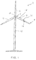
- Fig. 1 shows in a simplified schematic view of a wind turbine 2, the rotor blades 4 extending between a rotor blade root 6 and a rotor blade tip 8.
- the rotor blades 4 are connected at their rotor blade roots 6 with a hub 10 which drives the main shaft of the wind turbine 2.
- the rotor of the wind turbine 2 including the machine house, which receives the other components, are mounted on a supporting structure 12, for example a tower.
- the rotor blades 4 each comprise a suction side 14 (in Fig. 1 not visible), a pressure side 26, a rotor blade nose 16 and a rotor blade trailing edge 18 (shown only on one of the rotor blades with reference numerals).
- the suction and pressure side 14, 26 and the rotor blade nose 16 and rotor blade trailing edge 18 extend between the rotor blade root 6 and the rotor blade tip 8. They define an aerodynamically effective profile of the rotor blade 4.
- the rotor blades 4 of the wind turbine 2 shown are optimized with regard to their sound emission. In order to obtain such a sound-optimized rotor blade profile, a performance-optimized profile of the rotor blade 4 is first determined. This is done for example by numerical simulations or by practical experiments.
- the performance-optimized profile of the rotor blade 4 is aerodynamically optimized with regard to a power yield of the rotor blade 4.
- Fig. 2 shows a sound-optimized rotor blade 4 in a schematically simplified plan view of its suction side 14.
- a rotor blade end 20 which includes the rotor blade tip 8
- the measures taken in detail will be related to the Fig. 7 to 11 explained.
- the rotor blade 4 is provided in a blade root region 22 on its suction side 14 with vortex generators 24.
- Fig. 3 shows in a simplified schematic view a cross section through the rotor blade 4 in the blade root region 22, along the in Fig. 2 Level III-III.
- a vortex generator 24 is shown by way of example.
- a trailing edge web 2 (also referred to as tab) is provided at the transition between the pressure side 26 to the rotor blade trailing edge 18.
- the blade root portion 22 extends from the rotor blade root 6 to a second profile plane 30 (shown in dashed line).
- the rotor blade 4 is overflowed in the second profile plane 30 with a relative speed of 30 m / s.
- a power region 32 adjoins the blade root region 22. This extends from the second profile plane 30 in the direction of the rotor blade tip 8 to a first profile plane 34, to which reference should be made later.
- the rotor blade 4 has a performance-optimized profile. There are also made in this area no measures to Schalloptimtechnik the rotor blade 4.
- the power region 32 is followed by a middle section 36 in the direction of the rotor blade tip 8.
- the middle section 36 extends starting from the rotor blade end region 20 in the direction of the rotor blade root 6 up to the first profile plane 34.
- the rotor blade 4 is overflowed at nominal power of the wind energy plant 2 with a relative speed of 55 m / s.
- the rotor blade 4 In the middle section 36 of the rotor blade 4, this is provided on the rotor blade trailing edge 18 with trailing edge serrations 38. Both in the rotor blade end region 20 and in the power region 32 which is further in the direction of the blade root 6, the rotor blade 4 has no trailing edge serrations 38.
- the trailing edge serrations 38 also referred to as serrations, reduce the noise emission of the rotor blade 4.
- Fig. 4 shows in a schematically simplified cross section, the profile of the rotor blade 4 in the in Fig. 2 level designated IV-IV.
- the trailing edge serrations 38 are configured to have a maximum length L1 that is less than 20% of a length L2 of the chord 40.
- the maximum length L1 of the trailing edge serrations 38 and the length L2 of the chord 40 at each identical longitudinal position of the rotor blade 4, ie at an identical distance from the rotor blade root 6 and the rotor blade tip 8 is considered.
- the maximum length L1 of the trailing edge serrations 38 is measured starting from the rotor blade trailing edge 18.
- the trailing edge serrations 38 are inclined at an angle ⁇ with respect to a direction 42 of the chord 40.
- the maximum length of the trailing edge serrations 38 is determined when the angle ⁇ is 0 °, that is, the trailing edge serrations 38 extend in the direction 42 of the chord 40.
- the profile is also chosen, for example, such that a ratio of the profile thickness PD to the chord length L2 is less than 0.24.
- the rotor blade 4 is provided, for example, on the rotor blade nose 16 with erosion protection 44.
- the erosion protection 44 is integrated, for example, with a step height of less than 0.2 mm in a surface of the rotor blade 4.
- Fig. 5 shows a detail view of in Fig. 4 shown cross section in the region of the rotor blade trailing edge 18.
- a material thickness d of the trailing edge serrations 38 is for example less than 5 mm.
- the trailing edge teeth 38 for example, glued step-free with the profile of the rotor blade 4.
- Fig. 6 shows in a schematically simplified plan view of a portion of the trailing edge teeth 38.
- the prongs are for example designed so that their maximum length L1 is at least twice as large as their width b.
- the rotor blade 4 is provided, for example, with a tangential blow-out slot 46 (cf. Fig. 2 ) Mistake.
- Blow-out slot 46 extends on the suction side 14 of the rotor blade 4, starting from a third profile plane 48 in the direction of the rotor blade tip 8.
- the third profile plane 48 is arranged, for example, at a relative blade length of at least approximately 80%.
- the blow-out slot 46 further extends, for example, both in the middle section 36 and in the rotor blade end region 20.
- the relative blade length r / R is understood to mean the quotient of the radial position r (the distance from the center of the rotor) and the rotor radius R.
- the aforementioned measures can be taken individually or in combination in order to reduce the noise emission of the rotor blade 4.
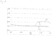
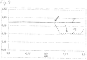
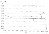
- the individual measures are based on the representations in the 8 to 11 again explained in detail, showing different sizes, which are each applied over relative blade length r / R.
- a solid line the course of the respective size in a performance-optimized profile 50 is shown in each case.
- the deviating profile of the respective size is shown in dashed line, as it is present in a sound-optimized profile 52.
- Fig. 8 shows a relative nose radius of the rotor blade 4. As indicated by an arrow, the relative nose radius is raised in the sound-optimized profile 52. The changes are made from a relative blade length r / R of about 0.9.
- Fig. 9 shows a relative maximum thickness of the rotor blade 4.
- the arrow indicates that the maximum thickness of the rotor blade 4 in the rotor blade end region 20 is reduced.
- a position of the maximum profile thickness migrates in the direction of the rotor blade nose 16. This position is for example at the edge shown with a double arrow, with a relative blade length of about 0.9, from which a change in the sound-optimized rotor blade profile 52 is made.
- Fig. 10 shows a maximum curvature of the rotor blade 4.
- the maximum curvature of the profile is reduced. This change is made from a relative blade length r / R of about 0.92. It is further provided that at the rotor blade tip 8, so a relative length of 1, the maximum curvature drops to zero.
- Fig. 11 shows a maximum curvature of the rotor blade 4. As indicated by an arrow, the maximum curvature is raised in the rotor blade end portion 20, it migrates in the direction of the rotor blade trailing edge 18. At the rotor blade tip 8, the maximum curvature drops, for example to zero.
- the rotor blade 4 is approximately in Fig. 12 shown rotor blade profile.
Landscapes
- Engineering & Computer Science (AREA)
- Physics & Mathematics (AREA)
- Fluid Mechanics (AREA)
- Life Sciences & Earth Sciences (AREA)
- Sustainable Development (AREA)
- Sustainable Energy (AREA)
- Chemical & Material Sciences (AREA)
- Combustion & Propulsion (AREA)
- Mechanical Engineering (AREA)
- General Engineering & Computer Science (AREA)
- Wind Motors (AREA)
Applications Claiming Priority (1)
| Application Number | Priority Date | Filing Date | Title |
|---|---|---|---|
| DE102015012427.7A DE102015012427A1 (de) | 2015-09-25 | 2015-09-25 | Rotorblatt mit einem schalloptimierten Profil sowie Verfahren zum Herstellen eines Rotorblatts |
Publications (2)
| Publication Number | Publication Date |
|---|---|
| EP3147499A1 true EP3147499A1 (fr) | 2017-03-29 |
| EP3147499B1 EP3147499B1 (fr) | 2020-04-08 |
Family
ID=56876958
Family Applications (1)
| Application Number | Title | Priority Date | Filing Date |
|---|---|---|---|
| EP16187323.7A Active EP3147499B1 (fr) | 2015-09-25 | 2016-09-06 | Pale de rotor a profil optimise contre le bruit et procede de fabrication d'une pale de rotor |
Country Status (4)
| Country | Link |
|---|---|
| EP (1) | EP3147499B1 (fr) |
| DE (1) | DE102015012427A1 (fr) |
| DK (1) | DK3147499T3 (fr) |
| ES (1) | ES2794787T3 (fr) |
Cited By (5)
| Publication number | Priority date | Publication date | Assignee | Title |
|---|---|---|---|---|
| EP3763937A1 (fr) | 2019-07-11 | 2021-01-13 | FlowGen Development & Management GmbH | Pale de rotor pour une éolienne et éolienne |
| CN112585350A (zh) * | 2018-08-31 | 2021-03-30 | 通用电气公司 | 具有弧形锯齿的用于风力涡轮转子叶片的消音器 |
| CN113090471A (zh) * | 2019-12-23 | 2021-07-09 | 新疆金风科技股份有限公司 | 风力发电机组的塔架净空音频监测系统、方法及装置 |
| CN113357080A (zh) * | 2021-06-10 | 2021-09-07 | 中科宇能科技发展有限公司 | 一种风电叶片吹气环量控制系统 |
| US20220228551A1 (en) * | 2019-05-17 | 2022-07-21 | Wobben Properties Gmbh | Rotor blade and wind turbine |
Citations (6)
| Publication number | Priority date | Publication date | Assignee | Title |
|---|---|---|---|---|
| US20030099546A1 (en) * | 2001-11-26 | 2003-05-29 | Henrik Stiesdal | Method for improvement of the efficiency of a wind turbine rotor |
| EP1674723A2 (fr) * | 2004-12-23 | 2006-06-28 | General Electric Company | Modification active de l'écoulement sur pales d'une éolienne |
| US20110142666A1 (en) | 2010-11-15 | 2011-06-16 | General Electric Company | Noise reducer for rotor blade in wind turbine |
| US20110150664A1 (en) * | 2009-12-22 | 2011-06-23 | Siegfried Mickeler | Aeroacoustic rotor blade for a wind turbine, and wind turbine equipped therewith |
| EP2682602A1 (fr) * | 2011-02-28 | 2014-01-08 | Mitsubishi Heavy Industries, Ltd. | Pale de turbine éolienne et générateur d'électricité éolienne équipé de cette pale |
| WO2014170232A1 (fr) * | 2013-04-17 | 2014-10-23 | Lm Wp Patent Holding A/S | Procédé de réparation d'une pale de turbine éolienne |
Family Cites Families (7)
| Publication number | Priority date | Publication date | Assignee | Title |
|---|---|---|---|---|
| CN104929866B (zh) * | 2010-10-22 | 2018-05-22 | 三菱重工业株式会社 | 风车翼及具备该风车翼的风力发电装置以及风车翼的设计方法 |
| US8414261B2 (en) | 2011-05-31 | 2013-04-09 | General Electric Company | Noise reducer for rotor blade in wind turbine |
| ES2685827T3 (es) | 2011-12-19 | 2018-10-11 | Lm Wind Power International Technology Ii Aps | Una protección contra la erosión para una pala de turbina eólica |
| DE102013006203B4 (de) | 2012-04-30 | 2024-10-10 | HKB Turbinen GmbH & Co. KG | Rotorblatt für eine Windkraftanlage |
| US10677217B2 (en) * | 2012-10-03 | 2020-06-09 | General Electric Company | Wind turbine and method of operating the same |
| US20140093380A1 (en) | 2012-10-03 | 2014-04-03 | General Electric Company | Noise reduction tab and method for wind turbine rotor blade |
| DK177928B1 (en) * | 2013-06-17 | 2015-01-19 | Envision Energy Denmark Aps | Wind turbine blade with extended shell section |
-
2015
- 2015-09-25 DE DE102015012427.7A patent/DE102015012427A1/de not_active Withdrawn
-
2016
- 2016-09-06 ES ES16187323T patent/ES2794787T3/es active Active
- 2016-09-06 DK DK16187323.7T patent/DK3147499T3/da active
- 2016-09-06 EP EP16187323.7A patent/EP3147499B1/fr active Active
Patent Citations (6)
| Publication number | Priority date | Publication date | Assignee | Title |
|---|---|---|---|---|
| US20030099546A1 (en) * | 2001-11-26 | 2003-05-29 | Henrik Stiesdal | Method for improvement of the efficiency of a wind turbine rotor |
| EP1674723A2 (fr) * | 2004-12-23 | 2006-06-28 | General Electric Company | Modification active de l'écoulement sur pales d'une éolienne |
| US20110150664A1 (en) * | 2009-12-22 | 2011-06-23 | Siegfried Mickeler | Aeroacoustic rotor blade for a wind turbine, and wind turbine equipped therewith |
| US20110142666A1 (en) | 2010-11-15 | 2011-06-16 | General Electric Company | Noise reducer for rotor blade in wind turbine |
| EP2682602A1 (fr) * | 2011-02-28 | 2014-01-08 | Mitsubishi Heavy Industries, Ltd. | Pale de turbine éolienne et générateur d'électricité éolienne équipé de cette pale |
| WO2014170232A1 (fr) * | 2013-04-17 | 2014-10-23 | Lm Wp Patent Holding A/S | Procédé de réparation d'une pale de turbine éolienne |
Cited By (7)
| Publication number | Priority date | Publication date | Assignee | Title |
|---|---|---|---|---|
| CN112585350A (zh) * | 2018-08-31 | 2021-03-30 | 通用电气公司 | 具有弧形锯齿的用于风力涡轮转子叶片的消音器 |
| US20220228551A1 (en) * | 2019-05-17 | 2022-07-21 | Wobben Properties Gmbh | Rotor blade and wind turbine |
| EP3763937A1 (fr) | 2019-07-11 | 2021-01-13 | FlowGen Development & Management GmbH | Pale de rotor pour une éolienne et éolienne |
| WO2021004853A1 (fr) | 2019-07-11 | 2021-01-14 | Flowgen Development & Management Gmbh | Pale de rotor pour éolienne et éolienne |
| CN113090471A (zh) * | 2019-12-23 | 2021-07-09 | 新疆金风科技股份有限公司 | 风力发电机组的塔架净空音频监测系统、方法及装置 |
| CN113357080A (zh) * | 2021-06-10 | 2021-09-07 | 中科宇能科技发展有限公司 | 一种风电叶片吹气环量控制系统 |
| CN113357080B (zh) * | 2021-06-10 | 2023-02-28 | 中科宇能科技发展有限公司 | 一种风电叶片吹气环量控制系统 |
Also Published As
| Publication number | Publication date |
|---|---|
| EP3147499B1 (fr) | 2020-04-08 |
| ES2794787T3 (es) | 2020-11-19 |
| DE102015012427A1 (de) | 2017-03-30 |
| DK3147499T3 (da) | 2020-06-29 |
Similar Documents
| Publication | Publication Date | Title |
|---|---|---|
| EP1514023B1 (fr) | Eolienne | |
| EP3147499B1 (fr) | Pale de rotor a profil optimise contre le bruit et procede de fabrication d'une pale de rotor | |
| DE102008007908B4 (de) | Rotorflügelanordnung und Abströmkantenanordnung | |
| EP2280163B1 (fr) | Eolienne et pale de rotor d'une eolienne | |
| EP2998572A1 (fr) | Pale de rotor d'éoliennes | |
| EP2339171A2 (fr) | Pale pour une éolienne | |
| EP2245298B1 (fr) | Configuration d'une aube de rotor pour une turbine wells | |
| DE102011050661A1 (de) | Rotorblatt einer Windenergieanlage | |
| DE102013206437A1 (de) | Rotorblatt einer Windenergieanlage und Windenergieanlage | |
| DE102017117843A1 (de) | Rotorblatt eines Rotors einer Windenergieanlage, Windenergieanlage und Verfahren zur Verbesserung des Wirkungsgrades eines Rotors einer Windenergieanlage | |
| WO2015062710A1 (fr) | Pale de rotor d'une éolienne et éolienne | |
| EP3399183B1 (fr) | Pale de rotor d'une éolienne | |
| EP3844384B1 (fr) | Rotor comprenant une pale de rotor, éolienne et procédé d'optimisation d'une éolienne | |
| EP3969743B1 (fr) | Pale de rotor et méthode de conception d'une pale de rotor d'une eolienne. | |
| DE102018117398A1 (de) | Rotorblatt für eine Windenergieanlage und Windenergieanlage | |
| WO2010000229A2 (fr) | Grille d'aubes pour une turbomachine et turbomachine comportant une telle grille | |
| DE102009018924A1 (de) | Bidirektional anströmbare Turbine | |
| EP3735530B1 (fr) | Pale de rotor pour éolienne et procédé | |
| EP3969741B1 (fr) | Pale de rotor et éolienne | |
| EP4464889A2 (fr) | Pale de rotor d'une éolienne | |
| DE102014200644A1 (de) | Strangprofil zur Herstellung einer Schaufel eines Nachleitrads | |
| EP3954892A2 (fr) | Pale de rotor pour une éolienne, rotor pour une éolienne, construction et éolienne | |
| EP2650475A1 (fr) | Pale pour une turbomachine, agencement d'aubes ainsi que la turbomachine | |
| EP3604796A1 (fr) | Pale de rotor pour une éolienne, éolienne, procédé d'extension d'une pale de rotor ainsi que procédé de fabrication d'une pale de rotor | |
| WO2016162350A1 (fr) | Pale de rotor d'éolienne |
Legal Events
| Date | Code | Title | Description |
|---|---|---|---|
| PUAI | Public reference made under article 153(3) epc to a published international application that has entered the european phase |
Free format text: ORIGINAL CODE: 0009012 |
|
| STAA | Information on the status of an ep patent application or granted ep patent |
Free format text: STATUS: THE APPLICATION HAS BEEN PUBLISHED |
|
| AK | Designated contracting states |
Kind code of ref document: A1 Designated state(s): AL AT BE BG CH CY CZ DE DK EE ES FI FR GB GR HR HU IE IS IT LI LT LU LV MC MK MT NL NO PL PT RO RS SE SI SK SM TR |
|
| AX | Request for extension of the european patent |
Extension state: BA ME |
|
| STAA | Information on the status of an ep patent application or granted ep patent |
Free format text: STATUS: REQUEST FOR EXAMINATION WAS MADE |
|
| 17P | Request for examination filed |
Effective date: 20170726 |
|
| RBV | Designated contracting states (corrected) |
Designated state(s): AL AT BE BG CH CY CZ DE DK EE ES FI FR GB GR HR HU IE IS IT LI LT LU LV MC MK MT NL NO PL PT RO RS SE SI SK SM TR |
|
| STAA | Information on the status of an ep patent application or granted ep patent |
Free format text: STATUS: EXAMINATION IS IN PROGRESS |
|
| 17Q | First examination report despatched |
Effective date: 20180103 |
|
| GRAP | Despatch of communication of intention to grant a patent |
Free format text: ORIGINAL CODE: EPIDOSNIGR1 |
|
| STAA | Information on the status of an ep patent application or granted ep patent |
Free format text: STATUS: GRANT OF PATENT IS INTENDED |
|
| INTG | Intention to grant announced |
Effective date: 20191017 |
|
| GRAS | Grant fee paid |
Free format text: ORIGINAL CODE: EPIDOSNIGR3 |
|
| GRAA | (expected) grant |
Free format text: ORIGINAL CODE: 0009210 |
|
| STAA | Information on the status of an ep patent application or granted ep patent |
Free format text: STATUS: THE PATENT HAS BEEN GRANTED |
|
| AK | Designated contracting states |
Kind code of ref document: B1 Designated state(s): AL AT BE BG CH CY CZ DE DK EE ES FI FR GB GR HR HU IE IS IT LI LT LU LV MC MK MT NL NO PL PT RO RS SE SI SK SM TR |
|
| RAP1 | Party data changed (applicant data changed or rights of an application transferred) |
Owner name: SENVION DEUTSCHLAND GMBH |
|
| REG | Reference to a national code |
Ref country code: CH Ref legal event code: EP Ref country code: AT Ref legal event code: REF Ref document number: 1254730 Country of ref document: AT Kind code of ref document: T Effective date: 20200415 |
|
| REG | Reference to a national code |
Ref country code: DE Ref legal event code: R096 Ref document number: 502016009444 Country of ref document: DE |
|
| REG | Reference to a national code |
Ref country code: IE Ref legal event code: FG4D Free format text: LANGUAGE OF EP DOCUMENT: GERMAN |
|
| REG | Reference to a national code |
Ref country code: DK Ref legal event code: T3 Effective date: 20200624 |
|
| REG | Reference to a national code |
Ref country code: NL Ref legal event code: MP Effective date: 20200408 |
|
| REG | Reference to a national code |
Ref country code: LT Ref legal event code: MG4D |
|
| PG25 | Lapsed in a contracting state [announced via postgrant information from national office to epo] |
Ref country code: SE Free format text: LAPSE BECAUSE OF FAILURE TO SUBMIT A TRANSLATION OF THE DESCRIPTION OR TO PAY THE FEE WITHIN THE PRESCRIBED TIME-LIMIT Effective date: 20200408 Ref country code: NL Free format text: LAPSE BECAUSE OF FAILURE TO SUBMIT A TRANSLATION OF THE DESCRIPTION OR TO PAY THE FEE WITHIN THE PRESCRIBED TIME-LIMIT Effective date: 20200408 Ref country code: LT Free format text: LAPSE BECAUSE OF FAILURE TO SUBMIT A TRANSLATION OF THE DESCRIPTION OR TO PAY THE FEE WITHIN THE PRESCRIBED TIME-LIMIT Effective date: 20200408 Ref country code: GR Free format text: LAPSE BECAUSE OF FAILURE TO SUBMIT A TRANSLATION OF THE DESCRIPTION OR TO PAY THE FEE WITHIN THE PRESCRIBED TIME-LIMIT Effective date: 20200709 Ref country code: PT Free format text: LAPSE BECAUSE OF FAILURE TO SUBMIT A TRANSLATION OF THE DESCRIPTION OR TO PAY THE FEE WITHIN THE PRESCRIBED TIME-LIMIT Effective date: 20200817 Ref country code: NO Free format text: LAPSE BECAUSE OF FAILURE TO SUBMIT A TRANSLATION OF THE DESCRIPTION OR TO PAY THE FEE WITHIN THE PRESCRIBED TIME-LIMIT Effective date: 20200708 Ref country code: IS Free format text: LAPSE BECAUSE OF FAILURE TO SUBMIT A TRANSLATION OF THE DESCRIPTION OR TO PAY THE FEE WITHIN THE PRESCRIBED TIME-LIMIT Effective date: 20200808 Ref country code: FI Free format text: LAPSE BECAUSE OF FAILURE TO SUBMIT A TRANSLATION OF THE DESCRIPTION OR TO PAY THE FEE WITHIN THE PRESCRIBED TIME-LIMIT Effective date: 20200408 |
|
| REG | Reference to a national code |
Ref country code: ES Ref legal event code: FG2A Ref document number: 2794787 Country of ref document: ES Kind code of ref document: T3 Effective date: 20201119 |
|
| PG25 | Lapsed in a contracting state [announced via postgrant information from national office to epo] |
Ref country code: LV Free format text: LAPSE BECAUSE OF FAILURE TO SUBMIT A TRANSLATION OF THE DESCRIPTION OR TO PAY THE FEE WITHIN THE PRESCRIBED TIME-LIMIT Effective date: 20200408 Ref country code: HR Free format text: LAPSE BECAUSE OF FAILURE TO SUBMIT A TRANSLATION OF THE DESCRIPTION OR TO PAY THE FEE WITHIN THE PRESCRIBED TIME-LIMIT Effective date: 20200408 Ref country code: BG Free format text: LAPSE BECAUSE OF FAILURE TO SUBMIT A TRANSLATION OF THE DESCRIPTION OR TO PAY THE FEE WITHIN THE PRESCRIBED TIME-LIMIT Effective date: 20200708 Ref country code: RS Free format text: LAPSE BECAUSE OF FAILURE TO SUBMIT A TRANSLATION OF THE DESCRIPTION OR TO PAY THE FEE WITHIN THE PRESCRIBED TIME-LIMIT Effective date: 20200408 |
|
| PG25 | Lapsed in a contracting state [announced via postgrant information from national office to epo] |
Ref country code: AL Free format text: LAPSE BECAUSE OF FAILURE TO SUBMIT A TRANSLATION OF THE DESCRIPTION OR TO PAY THE FEE WITHIN THE PRESCRIBED TIME-LIMIT Effective date: 20200408 |
|
| REG | Reference to a national code |
Ref country code: DE Ref legal event code: R097 Ref document number: 502016009444 Country of ref document: DE |
|
| PG25 | Lapsed in a contracting state [announced via postgrant information from national office to epo] |
Ref country code: IT Free format text: LAPSE BECAUSE OF FAILURE TO SUBMIT A TRANSLATION OF THE DESCRIPTION OR TO PAY THE FEE WITHIN THE PRESCRIBED TIME-LIMIT Effective date: 20200408 Ref country code: RO Free format text: LAPSE BECAUSE OF FAILURE TO SUBMIT A TRANSLATION OF THE DESCRIPTION OR TO PAY THE FEE WITHIN THE PRESCRIBED TIME-LIMIT Effective date: 20200408 Ref country code: EE Free format text: LAPSE BECAUSE OF FAILURE TO SUBMIT A TRANSLATION OF THE DESCRIPTION OR TO PAY THE FEE WITHIN THE PRESCRIBED TIME-LIMIT Effective date: 20200408 Ref country code: CZ Free format text: LAPSE BECAUSE OF FAILURE TO SUBMIT A TRANSLATION OF THE DESCRIPTION OR TO PAY THE FEE WITHIN THE PRESCRIBED TIME-LIMIT Effective date: 20200408 Ref country code: SM Free format text: LAPSE BECAUSE OF FAILURE TO SUBMIT A TRANSLATION OF THE DESCRIPTION OR TO PAY THE FEE WITHIN THE PRESCRIBED TIME-LIMIT Effective date: 20200408 |
|
| PLBE | No opposition filed within time limit |
Free format text: ORIGINAL CODE: 0009261 |
|
| STAA | Information on the status of an ep patent application or granted ep patent |
Free format text: STATUS: NO OPPOSITION FILED WITHIN TIME LIMIT |
|
| PG25 | Lapsed in a contracting state [announced via postgrant information from national office to epo] |
Ref country code: PL Free format text: LAPSE BECAUSE OF FAILURE TO SUBMIT A TRANSLATION OF THE DESCRIPTION OR TO PAY THE FEE WITHIN THE PRESCRIBED TIME-LIMIT Effective date: 20200408 Ref country code: SK Free format text: LAPSE BECAUSE OF FAILURE TO SUBMIT A TRANSLATION OF THE DESCRIPTION OR TO PAY THE FEE WITHIN THE PRESCRIBED TIME-LIMIT Effective date: 20200408 |
|
| 26N | No opposition filed |
Effective date: 20210112 |
|
| PG25 | Lapsed in a contracting state [announced via postgrant information from national office to epo] |
Ref country code: MC Free format text: LAPSE BECAUSE OF FAILURE TO SUBMIT A TRANSLATION OF THE DESCRIPTION OR TO PAY THE FEE WITHIN THE PRESCRIBED TIME-LIMIT Effective date: 20200408 |
|
| REG | Reference to a national code |
Ref country code: CH Ref legal event code: PL |
|
| PG25 | Lapsed in a contracting state [announced via postgrant information from national office to epo] |
Ref country code: SI Free format text: LAPSE BECAUSE OF FAILURE TO SUBMIT A TRANSLATION OF THE DESCRIPTION OR TO PAY THE FEE WITHIN THE PRESCRIBED TIME-LIMIT Effective date: 20200408 |
|
| REG | Reference to a national code |
Ref country code: BE Ref legal event code: MM Effective date: 20200930 |
|
| PG25 | Lapsed in a contracting state [announced via postgrant information from national office to epo] |
Ref country code: LU Free format text: LAPSE BECAUSE OF NON-PAYMENT OF DUE FEES Effective date: 20200906 |
|
| PG25 | Lapsed in a contracting state [announced via postgrant information from national office to epo] |
Ref country code: CH Free format text: LAPSE BECAUSE OF NON-PAYMENT OF DUE FEES Effective date: 20200930 Ref country code: BE Free format text: LAPSE BECAUSE OF NON-PAYMENT OF DUE FEES Effective date: 20200930 Ref country code: IE Free format text: LAPSE BECAUSE OF NON-PAYMENT OF DUE FEES Effective date: 20200906 Ref country code: LI Free format text: LAPSE BECAUSE OF NON-PAYMENT OF DUE FEES Effective date: 20200930 |
|
| PG25 | Lapsed in a contracting state [announced via postgrant information from national office to epo] |
Ref country code: TR Free format text: LAPSE BECAUSE OF FAILURE TO SUBMIT A TRANSLATION OF THE DESCRIPTION OR TO PAY THE FEE WITHIN THE PRESCRIBED TIME-LIMIT Effective date: 20200408 Ref country code: MT Free format text: LAPSE BECAUSE OF FAILURE TO SUBMIT A TRANSLATION OF THE DESCRIPTION OR TO PAY THE FEE WITHIN THE PRESCRIBED TIME-LIMIT Effective date: 20200408 Ref country code: CY Free format text: LAPSE BECAUSE OF FAILURE TO SUBMIT A TRANSLATION OF THE DESCRIPTION OR TO PAY THE FEE WITHIN THE PRESCRIBED TIME-LIMIT Effective date: 20200408 |
|
| PG25 | Lapsed in a contracting state [announced via postgrant information from national office to epo] |
Ref country code: MK Free format text: LAPSE BECAUSE OF FAILURE TO SUBMIT A TRANSLATION OF THE DESCRIPTION OR TO PAY THE FEE WITHIN THE PRESCRIBED TIME-LIMIT Effective date: 20200408 |
|
| REG | Reference to a national code |
Ref country code: AT Ref legal event code: MM01 Ref document number: 1254730 Country of ref document: AT Kind code of ref document: T Effective date: 20210906 |
|
| PG25 | Lapsed in a contracting state [announced via postgrant information from national office to epo] |
Ref country code: AT Free format text: LAPSE BECAUSE OF NON-PAYMENT OF DUE FEES Effective date: 20210906 |
|
| PGFP | Annual fee paid to national office [announced via postgrant information from national office to epo] |
Ref country code: DE Payment date: 20240926 Year of fee payment: 9 |
|
| PGFP | Annual fee paid to national office [announced via postgrant information from national office to epo] |
Ref country code: DK Payment date: 20240925 Year of fee payment: 9 |
|
| PGFP | Annual fee paid to national office [announced via postgrant information from national office to epo] |
Ref country code: GB Payment date: 20240924 Year of fee payment: 9 |
|
| PGFP | Annual fee paid to national office [announced via postgrant information from national office to epo] |
Ref country code: FR Payment date: 20240925 Year of fee payment: 9 |
|
| PGFP | Annual fee paid to national office [announced via postgrant information from national office to epo] |
Ref country code: ES Payment date: 20241021 Year of fee payment: 9 |
|
| REG | Reference to a national code |
Ref country code: DK Ref legal event code: EBP Effective date: 20250930 |