EP3147507A1 - Drehkolbenverdichter für eine wärmepumpe - Google Patents
Drehkolbenverdichter für eine wärmepumpe Download PDFInfo
- Publication number
- EP3147507A1 EP3147507A1 EP15382463.6A EP15382463A EP3147507A1 EP 3147507 A1 EP3147507 A1 EP 3147507A1 EP 15382463 A EP15382463 A EP 15382463A EP 3147507 A1 EP3147507 A1 EP 3147507A1
- Authority
- EP
- European Patent Office
- Prior art keywords
- compressor
- working fluid
- service
- pipe
- heat pump
- Prior art date
- Legal status (The legal status is an assumption and is not a legal conclusion. Google has not performed a legal analysis and makes no representation as to the accuracy of the status listed.)
- Withdrawn
Links
- 239000012530 fluid Substances 0.000 claims abstract description 36
- 238000000034 method Methods 0.000 claims abstract description 10
- 239000010949 copper Substances 0.000 claims description 12
- 229910052802 copper Inorganic materials 0.000 claims description 11
- RYGMFSIKBFXOCR-UHFFFAOYSA-N Copper Chemical compound [Cu] RYGMFSIKBFXOCR-UHFFFAOYSA-N 0.000 claims description 10
- 239000004411 aluminium Substances 0.000 claims description 3
- XAGFODPZIPBFFR-UHFFFAOYSA-N aluminium Chemical compound [Al] XAGFODPZIPBFFR-UHFFFAOYSA-N 0.000 claims description 3
- 229910052782 aluminium Inorganic materials 0.000 claims description 3
- 239000003507 refrigerant Substances 0.000 description 12
- 238000005219 brazing Methods 0.000 description 6
- 239000000463 material Substances 0.000 description 5
- 238000001816 cooling Methods 0.000 description 4
- 238000001035 drying Methods 0.000 description 3
- 238000007789 sealing Methods 0.000 description 3
- BQCADISMDOOEFD-UHFFFAOYSA-N Silver Chemical compound [Ag] BQCADISMDOOEFD-UHFFFAOYSA-N 0.000 description 2
- 229910052709 silver Inorganic materials 0.000 description 2
- 239000004332 silver Substances 0.000 description 2
- 238000004088 simulation Methods 0.000 description 2
- 241000237983 Trochidae Species 0.000 description 1
- 238000005452 bending Methods 0.000 description 1
- 239000010725 compressor oil Substances 0.000 description 1
- 150000001879 copper Chemical class 0.000 description 1
- 238000002788 crimping Methods 0.000 description 1
- 238000005520 cutting process Methods 0.000 description 1
- 230000007812 deficiency Effects 0.000 description 1
- 230000001419 dependent effect Effects 0.000 description 1
- 229910052734 helium Inorganic materials 0.000 description 1
- 239000001307 helium Substances 0.000 description 1
- SWQJXJOGLNCZEY-UHFFFAOYSA-N helium atom Chemical compound [He] SWQJXJOGLNCZEY-UHFFFAOYSA-N 0.000 description 1
- 238000003754 machining Methods 0.000 description 1
- 230000035515 penetration Effects 0.000 description 1
- 238000010791 quenching Methods 0.000 description 1
- 230000000171 quenching effect Effects 0.000 description 1
- 238000005096 rolling process Methods 0.000 description 1
- 238000010408 sweeping Methods 0.000 description 1
- 238000005406 washing Methods 0.000 description 1
- 238000003466 welding Methods 0.000 description 1
Images

Classifications
-
- F—MECHANICAL ENGINEERING; LIGHTING; HEATING; WEAPONS; BLASTING
- F04—POSITIVE - DISPLACEMENT MACHINES FOR LIQUIDS; PUMPS FOR LIQUIDS OR ELASTIC FLUIDS
- F04C—ROTARY-PISTON, OR OSCILLATING-PISTON, POSITIVE-DISPLACEMENT MACHINES FOR LIQUIDS; ROTARY-PISTON, OR OSCILLATING-PISTON, POSITIVE-DISPLACEMENT PUMPS
- F04C23/00—Combinations of two or more pumps, each being of rotary-piston or oscillating-piston type, specially adapted for elastic fluids; Pumping installations specially adapted for elastic fluids; Multi-stage pumps specially adapted for elastic fluids
- F04C23/008—Hermetic pumps
-
- F—MECHANICAL ENGINEERING; LIGHTING; HEATING; WEAPONS; BLASTING
- F04—POSITIVE - DISPLACEMENT MACHINES FOR LIQUIDS; PUMPS FOR LIQUIDS OR ELASTIC FLUIDS
- F04C—ROTARY-PISTON, OR OSCILLATING-PISTON, POSITIVE-DISPLACEMENT MACHINES FOR LIQUIDS; ROTARY-PISTON, OR OSCILLATING-PISTON, POSITIVE-DISPLACEMENT PUMPS
- F04C2240/00—Components
- F04C2240/80—Other components
-
- F—MECHANICAL ENGINEERING; LIGHTING; HEATING; WEAPONS; BLASTING
- F04—POSITIVE - DISPLACEMENT MACHINES FOR LIQUIDS; PUMPS FOR LIQUIDS OR ELASTIC FLUIDS
- F04C—ROTARY-PISTON, OR OSCILLATING-PISTON, POSITIVE-DISPLACEMENT MACHINES FOR LIQUIDS; ROTARY-PISTON, OR OSCILLATING-PISTON, POSITIVE-DISPLACEMENT PUMPS
- F04C2240/00—Components
- F04C2240/80—Other components
- F04C2240/806—Pipes for fluids; Fittings therefor
Definitions
- the invention relates to a rotary compressor for a heat pump of a household appliance wherein the compressor comprises a low pressure inlet for a working fluid, a high pressure outlet for the working fluid, and a service inlet for charging or filling the working fluid into the heat pump.
- the invention is particularly useful for clothes dryers.
- heat pumps of household clothes dryers typically comprise - in that order - a compressor, a condenser, an expansion valve, and an evaporator which are connected by respective connection pipings to form a circuit.
- the circuit is filled or charged with working fluid and may thus also be called a "working fluid circuit".
- heat pumps have a dedicated pipe (called a service pipe) that is brazed to one of the connection pipings of the working fluid circuit between the high pressure outlet of the compressor and the expansion valve. The additional brazing may create additional points of leakage.
- brazed joints of the piping may suffer from deformations during its assembly process, especially during a helium leakage test, at a vacuum station, during charging of refrigerant, and during sealing of the service pipe. These deformations increase the risk of leakages and of generating noise in the pipes.
- brazing material comprising copper (Cu) with a certain content of silver (Ag) is used which achieves a higher ductility but increases costs compared to joints not requiring silver.
- the desire to use piping with pipes having a lower external diameter as a cost saving measure makes it more difficult to add the service pipe.
- the external diameter of the service pipe is 6 mm. If the external diameter of the service pipe near or equal to the external diameter of the pipes of the connection piping to which it is to be joined, it is required to drill up to 50% of the available surface of the connection piping. This results in a small or no penetration of the service pipe into the connection piping which results in a mechanically weak joint. This, in turn, leads to an increased risk of mechanical damage of the joint during operation, either by plastic deformation or as a result of fatigue forces.
- a tee connector 103 may be used to connect a service pipe 102 to a connection piping 101 a, 101b.
- the tee connector 103 fluidically connects the service pipe 102 to two separated pipes 101 a and 101b of the piping 101 a, 101b. While pipe 101 a connects to the high pressure outlet of the compressor (not shown), pipe 101b connects to the condenser (not shown). This, however, increases costs and the number of brazed connections (by two) with in turn increased a risk of leakages.
- a rotary compressor as rolling piston type compressor, for a heat pump of a household appliance
- the compressor comprises a low pressure inlet (also called suction port) for a working fluid and a high pressure outlet (also called discharge tube or discharge port) for the working fluid, and wherein the compressor further comprises a service inlet for charging the working fluid directly into the compressor.
- This compressor has the advantage that there is no need for attaching a service pipe to a connection piping of the heat pump. Thus, leakages caused by a respective joint between the service pipe and the connection piping can be avoided.
- a contact area between the service inlet and the compressor can be leak tested in advance to assembly without further effort since usually compressors are leak tested anyway. This even more reduces a risk of leakages of the working fluid. Additionally, this gives a better match between simulations and empirical tests from a vibration point of view.
- the household appliance can be a kitchen appliance or a laundry care appliance.
- the kitchen appliance can be a cooling appliance like a refrigerator or a freezer cabinet.
- the laundry care appliance can be a laundry drying appliance.
- the low pressure inlet may in particular be used for connecting a low pressure region of the compressor to a connection piping connecting the low pressure inlet to the evaporator.
- the high pressure outlet may in particular be used for connecting a high pressure region of the compressor to a connection piping connecting the high pressure outlet to the condenser.
- a piping may comprise one or more joint pipes.
- the working fluid may in particular be a refrigerant.
- the service inlet may be a separately manufactured hollow piece that is fixed to the compressor by welding ensuring leak tightness and thus connects an interior region of the compressor comprising the working fluid with the exterior of the compressor.
- the service inlet may be manufactured by working, in particular machining, an outer wall of the compressor, for example a top or bottom lid or a lateral wall.
- the service inlet leads to a high pressure region of the compressor. This gives the advantage that start-up problems can be avoided that would be caused by compressor oil sweeping when filling the working fluid, in particular refrigerant.
- the service inlet is positioned in a lid or top shell of the compressor.
- the lid of a rotary compressor usually acts as a wall of a high pressure region of the working fluid in the compressor such that this gives easy access to the high pressure region.
- the service inlet comprises or is a tube or pipe (in the following also called "service pipe”).
- service pipe can be joined in an automatic or semi-automatic way to the compressor lid (e.g. in the same way as for a high pressure outlet comprising a discharge pipe), thus avoiding the fully manual pipe-to-pipe brazing of a conventional service pipe.
- the service pipe may be fixed by brazing to a wall of the compressor.
- the service pipe is a straight pipe. This gives the advantage that a particularly small amount of material is needed. Also, the service pipe can be provided by simple cutting and does not require any bending. But the service pipe may also be bended to allow a better access directing its free end to a specific position.
- connection piping is 6 mm or smaller. This also enables a reduction of material.
- an outer diameter of the service pipe can be 6 mm or smaller. This diameter reduction from a current value of 8 mm can be achieved without regard for the service pipe and enables a particularly large reduction of material.
- the service pipe comprises copper.
- Copper has the advantage of being rather ductile such that it can easily be formed (e.g. quenched) to achieve a highly tight sealing to prevent leakage of the working fluid. Also, copper is simple to braze and chemically robust.
- the service pipe may in particular be made of copper of at least 90%, in particular at least 95%, in particular at least 99%, in particular at least 99.8%.
- the service pipe may comprise aluminium (Al).
- Al aluminium
- the service pipe may in particular be made of aluminium of at least 90%, in particular at least 95%, in particular at least 99%, in particular at least 99.8%.
- the service pipe penetrates the lid (i.e. protrudes from an inner surface into the interior of the compressor) at least 1 mm. This enables a particularly easy handling of the service pipe during its fixing to the lid.
- the service pipe has a length outside the compressor of at least 20 mm. This gives the advantage of having enough length to tightly seal the service pipe after filling or charging the heat pump with the working fluid.
- a household appliance comprising a heat pump having a rotary compressor and a service inlet for charging working fluid into the heat pump wherein the compressor is a compressor as described above.
- the household appliance can be a kitchen appliance or a laundry care appliance.
- the kitchen appliance can be a cooling appliance like a refrigerator and/or a freezer cabinet.
- the laundry care appliance can be a laundry drying appliance.
- the laundry drying appliance can be a stand-alone clothes dryer or a washing machine / clothes dryer combination.
- the object is further achieved by a method for filling or charging working fluid into a heat pump of a household appliance comprising a rotary compressor wherein the method comprises charging the working fluid directly into the compressor.
- the method achieves the same advantages as the compressor and the household appliance and can be evolved in analogy to the compressor and the household appliance.
- the method comprises charging the working fluid into the compressor through a service pipe into a high pressure region of the compressor wherein the service pipe leads through a wall of the compressor.
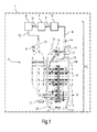
- Fig.1 shows a vertical cross-section of a single stage rotary compressor 1 vertically positioned in the appliance that can be used as a drive of a heat pump 2 of a household appliance in form of, e.g., a laundry dryer 3.
- a discharge tube or pipe 4 of the compressor 1 acts as a high pressure outlet for a working fluid (refrigerant R).
- the discharge pipe 4 is connected to an inlet of a condenser 5 via a first copper connection piping 6.
- An outlet of the condenser 5 is connected to an inlet of an expansion valve 7 via a second copper connection piping 8, and an outlet of the expansion valve 7 is connected to an inlet of an evaporator 9 via a third copper connection piping 10.
- An outlet of the evaporator 9 is connected to a suction tube or pipe 11 acting as a low pressure inlet of the compressor 1 via a fourth copper connection piping 12.
- the suction pipe 11 leads to a low pressure region 13 within the compressor 1.
- the incoming low-pressure refrigerant R is compressed by a compressing section 14 of the compressor 1.
- the compressing section 14 is driven by a motor 15.
- the compressed and thus high-pressure refrigerant R flows upwards to a high pressure region 16 of the compressor 1.
- the high pressure region 16 is capped by a top lid 17.
- the discharge pipe 4 leads through the lid 17 such that the refrigerant R can flow through the connection piping 6 to the condenser 5.
- the heat pump 2 comprises a cooling circuit for the refrigerant R composed of the components 1 and 4 to 12.
- a service inlet in form of a copper service pipe 18 is provided.
- the service pipe 18 is a straight pipe that leads through a hole in the top lid 17 and is tightly joint to the lid 17 e.g. by brazing. This enables an easy and inexpensive way to attach the service pipe 18, in particular by an automated or semi-automated process.
- the service pipe 18 (having an outer diameter of the pipe is 6 mm or smaller) penetrates the interior surface of the top lid 17 at least 1 mm and thus leads to the high pressure region 16 of the compressor 1. At the outside of the top lid 17, the service pipe 18 extends or has a length of at least 20 mm. After filling the refrigerant R directly into the compressor 1, this outer section is tightly sealed by quenching, e.g. by tightly crimping, the service pipe 18.
- the top lid 17 also comprises an electrical connector 19 for the motor 15.
- Fig.2 shows an oblique cut-out view onto a rotary compressor 21.
- the rotary compressor 21 is similar to the compressor 1 and may also be used to drive the heat pump 2.
- the rotary compressor 21 has a lid 22 where the discharge pipe 23 is located centrally and may be a straight pipe to enable an easier fixing. Consequently, the electrical connector 19 is moved off-center.
- the service pipe 18 is shown in its open, unquenched form.
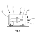
- Fig.5 shows lateral view of a rotary compressor 1 horizontally positioned that may also be used to drive the heat pump 2.
- the rotary compressor 1 has a top lid 22 where the discharge pipe 23 is located centrally, a bottom lid 25 and a lateral wall 24 in which the service pipe 18 is located and may be a bended pipe to enable an easier access.
- the present invention is not restricted to the described embodiments.
Landscapes
- Engineering & Computer Science (AREA)
- Mechanical Engineering (AREA)
- General Engineering & Computer Science (AREA)
- Detail Structures Of Washing Machines And Dryers (AREA)
Priority Applications (1)
| Application Number | Priority Date | Filing Date | Title |
|---|---|---|---|
| EP15382463.6A EP3147507A1 (de) | 2015-09-25 | 2015-09-25 | Drehkolbenverdichter für eine wärmepumpe |
Applications Claiming Priority (1)
| Application Number | Priority Date | Filing Date | Title |
|---|---|---|---|
| EP15382463.6A EP3147507A1 (de) | 2015-09-25 | 2015-09-25 | Drehkolbenverdichter für eine wärmepumpe |
Publications (1)
| Publication Number | Publication Date |
|---|---|
| EP3147507A1 true EP3147507A1 (de) | 2017-03-29 |
Family
ID=54252233
Family Applications (1)
| Application Number | Title | Priority Date | Filing Date |
|---|---|---|---|
| EP15382463.6A Withdrawn EP3147507A1 (de) | 2015-09-25 | 2015-09-25 | Drehkolbenverdichter für eine wärmepumpe |
Country Status (1)
| Country | Link |
|---|---|
| EP (1) | EP3147507A1 (de) |
Cited By (1)
| Publication number | Priority date | Publication date | Assignee | Title |
|---|---|---|---|---|
| EP4086538A1 (de) | 2021-05-03 | 2022-11-09 | BSH Hausgeräte GmbH | Kompressormodul mit mitteln zum kühlen und haushaltsgerät damit |
Citations (6)
| Publication number | Priority date | Publication date | Assignee | Title |
|---|---|---|---|---|
| JPS63280885A (ja) * | 1987-05-12 | 1988-11-17 | Sanyo Electric Co Ltd | 密閉型回転圧縮機 |
| JP2004293446A (ja) * | 2003-03-27 | 2004-10-21 | Mitsubishi Electric Corp | 密閉型圧縮機 |
| AT9232U1 (de) * | 2006-05-22 | 2007-06-15 | Acc Austria Gmbh | Kältemittelverdichter |
| US20090113740A1 (en) | 2007-11-06 | 2009-05-07 | Bsh Bosch Und Siemens Hausgeraete Gmbh | Dryer with heat pump |
| US20090139107A1 (en) | 2007-11-30 | 2009-06-04 | Bsh Bosch Und Siemens Hausgeraete Gmbh | Exhaust air dryer with a heat pump and a first fan |
| US20100083527A1 (en) | 2007-01-15 | 2010-04-08 | BSH Bosch und Siemens Hausgeräte GmbH | Condensation dryer comprising a heat pump and method for operating the same |
-
2015
- 2015-09-25 EP EP15382463.6A patent/EP3147507A1/de not_active Withdrawn
Patent Citations (6)
| Publication number | Priority date | Publication date | Assignee | Title |
|---|---|---|---|---|
| JPS63280885A (ja) * | 1987-05-12 | 1988-11-17 | Sanyo Electric Co Ltd | 密閉型回転圧縮機 |
| JP2004293446A (ja) * | 2003-03-27 | 2004-10-21 | Mitsubishi Electric Corp | 密閉型圧縮機 |
| AT9232U1 (de) * | 2006-05-22 | 2007-06-15 | Acc Austria Gmbh | Kältemittelverdichter |
| US20100083527A1 (en) | 2007-01-15 | 2010-04-08 | BSH Bosch und Siemens Hausgeräte GmbH | Condensation dryer comprising a heat pump and method for operating the same |
| US20090113740A1 (en) | 2007-11-06 | 2009-05-07 | Bsh Bosch Und Siemens Hausgeraete Gmbh | Dryer with heat pump |
| US20090139107A1 (en) | 2007-11-30 | 2009-06-04 | Bsh Bosch Und Siemens Hausgeraete Gmbh | Exhaust air dryer with a heat pump and a first fan |
Cited By (1)
| Publication number | Priority date | Publication date | Assignee | Title |
|---|---|---|---|---|
| EP4086538A1 (de) | 2021-05-03 | 2022-11-09 | BSH Hausgeräte GmbH | Kompressormodul mit mitteln zum kühlen und haushaltsgerät damit |
Similar Documents
| Publication | Publication Date | Title |
|---|---|---|
| CN107131366A (zh) | 一种管件连接结构及不锈钢管件与铜管的连接结构 | |
| JP2020109297A (ja) | 圧縮機 | |
| EP3409949A1 (de) | Rotationskompressor mit zwei zylindern | |
| CN102962633A (zh) | 储液器与压缩机的组装工艺 | |
| CN111902630A (zh) | 压缩机 | |
| EP3147507A1 (de) | Drehkolbenverdichter für eine wärmepumpe | |
| CN102338257A (zh) | 不锈钢消音器及其制造工艺 | |
| CN102962632A (zh) | 压缩机进气管与压缩机的连接方法 | |
| KR20140040228A (ko) | 밀폐형 컴프레서를 위한 커넥터 | |
| US6810681B2 (en) | Method of draining and recharging hermetic compressor oil | |
| CN101307848A (zh) | 铜管连接装置和方法 | |
| EP3683399B1 (de) | Drehkompressor und kühlkreisvorrichtung | |
| JP6088916B2 (ja) | 密閉型電動圧縮機 | |
| CN101761484A (zh) | 一种旋转式压缩机储液器与泵体的连接方法 | |
| CN215337202U (zh) | 一种用于制冷系统中罐体焊接的结构 | |
| KR101608493B1 (ko) | 어큐뮬레이터의 튜브 연결구조 | |
| CN201232775Y (zh) | 一种电磁控制阀和使用该电磁控制阀的空调制冷系统 | |
| CN103983055A (zh) | 汽液分离器输入输出结构及其制造工艺 | |
| WO2000007749A1 (en) | Method for joining metal tubes to the casing of refrigeration compressors | |
| CN222166473U (zh) | 压力检测工装 | |
| CN209324667U (zh) | 一种压缩机组件及压缩机 | |
| KR20160005446A (ko) | 냉장고용 증발기와 캐피러리 튜브 및 석션 파이프의 결합구조 및 그 결합 방법 | |
| KR101388191B1 (ko) | 파이프 연결방법 | |
| CN217926191U (zh) | 压缩机及制冷设备 | |
| EP4388258A1 (de) | Kühlschrank mit zusätzlichem rohr |
Legal Events
| Date | Code | Title | Description |
|---|---|---|---|
| PUAI | Public reference made under article 153(3) epc to a published international application that has entered the european phase |
Free format text: ORIGINAL CODE: 0009012 |
|
| AK | Designated contracting states |
Kind code of ref document: A1 Designated state(s): AL AT BE BG CH CY CZ DE DK EE ES FI FR GB GR HR HU IE IS IT LI LT LU LV MC MK MT NL NO PL PT RO RS SE SI SK SM TR |
|
| AX | Request for extension of the european patent |
Extension state: BA ME |
|
| STAA | Information on the status of an ep patent application or granted ep patent |
Free format text: STATUS: THE APPLICATION IS DEEMED TO BE WITHDRAWN |
|
| 18D | Application deemed to be withdrawn |
Effective date: 20170930 |