EP3147544B1 - Sealing device - Google Patents
Sealing device Download PDFInfo
- Publication number
- EP3147544B1 EP3147544B1 EP15796984.1A EP15796984A EP3147544B1 EP 3147544 B1 EP3147544 B1 EP 3147544B1 EP 15796984 A EP15796984 A EP 15796984A EP 3147544 B1 EP3147544 B1 EP 3147544B1
- Authority
- EP
- European Patent Office
- Prior art keywords
- shaft
- sealing device
- lip
- bumper
- dust lip
- Prior art date
- Legal status (The legal status is an assumption and is not a legal conclusion. Google has not performed a legal analysis and makes no representation as to the accuracy of the status listed.)
- Active
Links
Images


Classifications
-
- F—MECHANICAL ENGINEERING; LIGHTING; HEATING; WEAPONS; BLASTING
- F16—ENGINEERING ELEMENTS AND UNITS; GENERAL MEASURES FOR PRODUCING AND MAINTAINING EFFECTIVE FUNCTIONING OF MACHINES OR INSTALLATIONS; THERMAL INSULATION IN GENERAL
- F16J—PISTONS; CYLINDERS; SEALINGS
- F16J15/00—Sealings
- F16J15/16—Sealings between relatively-moving surfaces
- F16J15/32—Sealings between relatively-moving surfaces with elastic sealings, e.g. O-rings
- F16J15/3204—Sealings between relatively-moving surfaces with elastic sealings, e.g. O-rings with at least one lip
- F16J15/3232—Sealings between relatively-moving surfaces with elastic sealings, e.g. O-rings with at least one lip having two or more lips
-
- F—MECHANICAL ENGINEERING; LIGHTING; HEATING; WEAPONS; BLASTING
- F16—ENGINEERING ELEMENTS AND UNITS; GENERAL MEASURES FOR PRODUCING AND MAINTAINING EFFECTIVE FUNCTIONING OF MACHINES OR INSTALLATIONS; THERMAL INSULATION IN GENERAL
- F16J—PISTONS; CYLINDERS; SEALINGS
- F16J15/00—Sealings
- F16J15/16—Sealings between relatively-moving surfaces
- F16J15/32—Sealings between relatively-moving surfaces with elastic sealings, e.g. O-rings
- F16J15/3204—Sealings between relatively-moving surfaces with elastic sealings, e.g. O-rings with at least one lip
- F16J15/322—Sealings between relatively-moving surfaces with elastic sealings, e.g. O-rings with at least one lip supported in a direction perpendicular to the surfaces
-
- F—MECHANICAL ENGINEERING; LIGHTING; HEATING; WEAPONS; BLASTING
- F16—ENGINEERING ELEMENTS AND UNITS; GENERAL MEASURES FOR PRODUCING AND MAINTAINING EFFECTIVE FUNCTIONING OF MACHINES OR INSTALLATIONS; THERMAL INSULATION IN GENERAL
- F16J—PISTONS; CYLINDERS; SEALINGS
- F16J15/00—Sealings
- F16J15/16—Sealings between relatively-moving surfaces
- F16J15/32—Sealings between relatively-moving surfaces with elastic sealings, e.g. O-rings
- F16J15/3204—Sealings between relatively-moving surfaces with elastic sealings, e.g. O-rings with at least one lip
- F16J15/3224—Sealings between relatively-moving surfaces with elastic sealings, e.g. O-rings with at least one lip capable of accommodating changes in distances or misalignment between the surfaces, e.g. able to compensate for defaults of eccentricity or angular deviations
-
- F—MECHANICAL ENGINEERING; LIGHTING; HEATING; WEAPONS; BLASTING
- F16—ENGINEERING ELEMENTS AND UNITS; GENERAL MEASURES FOR PRODUCING AND MAINTAINING EFFECTIVE FUNCTIONING OF MACHINES OR INSTALLATIONS; THERMAL INSULATION IN GENERAL
- F16J—PISTONS; CYLINDERS; SEALINGS
- F16J15/00—Sealings
- F16J15/16—Sealings between relatively-moving surfaces
- F16J15/32—Sealings between relatively-moving surfaces with elastic sealings, e.g. O-rings
- F16J15/3244—Sealings between relatively-moving surfaces with elastic sealings, e.g. O-rings with hydrodynamic pumping action
-
- F—MECHANICAL ENGINEERING; LIGHTING; HEATING; WEAPONS; BLASTING
- F16—ENGINEERING ELEMENTS AND UNITS; GENERAL MEASURES FOR PRODUCING AND MAINTAINING EFFECTIVE FUNCTIONING OF MACHINES OR INSTALLATIONS; THERMAL INSULATION IN GENERAL
- F16J—PISTONS; CYLINDERS; SEALINGS
- F16J15/00—Sealings
- F16J15/16—Sealings between relatively-moving surfaces
- F16J15/32—Sealings between relatively-moving surfaces with elastic sealings, e.g. O-rings
- F16J15/3248—Sealings between relatively-moving surfaces with elastic sealings, e.g. O-rings provided with casings or supports
- F16J15/3252—Sealings between relatively-moving surfaces with elastic sealings, e.g. O-rings provided with casings or supports with rigid casings or supports
-
- F—MECHANICAL ENGINEERING; LIGHTING; HEATING; WEAPONS; BLASTING
- F16—ENGINEERING ELEMENTS AND UNITS; GENERAL MEASURES FOR PRODUCING AND MAINTAINING EFFECTIVE FUNCTIONING OF MACHINES OR INSTALLATIONS; THERMAL INSULATION IN GENERAL
- F16J—PISTONS; CYLINDERS; SEALINGS
- F16J15/00—Sealings
- F16J15/16—Sealings between relatively-moving surfaces
- F16J15/32—Sealings between relatively-moving surfaces with elastic sealings, e.g. O-rings
- F16J15/3268—Mounting of sealing rings
- F16J15/3276—Mounting of sealing rings with additional static sealing between the sealing, or its casing or support, and the surface on which it is mounted
-
- Y—GENERAL TAGGING OF NEW TECHNOLOGICAL DEVELOPMENTS; GENERAL TAGGING OF CROSS-SECTIONAL TECHNOLOGIES SPANNING OVER SEVERAL SECTIONS OF THE IPC; TECHNICAL SUBJECTS COVERED BY FORMER USPC CROSS-REFERENCE ART COLLECTIONS [XRACs] AND DIGESTS
- Y10—TECHNICAL SUBJECTS COVERED BY FORMER USPC
- Y10S—TECHNICAL SUBJECTS COVERED BY FORMER USPC CROSS-REFERENCE ART COLLECTIONS [XRACs] AND DIGESTS
- Y10S277/00—Seal for a joint or juncture
- Y10S277/91—O-ring seal
Definitions
- the present invention relates to a sealing device that seals an annular gap between a shaft and a housing.
- a sealing device such as an oil seal that includes a main lip that prevents leakage of a target liquid to be sealed such as oil, and a dust lip that prevents intrusion of a foreign object such as dust into a sealed area from the outside.
- this sealing device it is possible to seal an annular gap between a shaft and a housing.
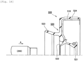
- Fig. 14 is a schematic cross-sectional view of the sealing device of a conventional example. Fig. 14 shows a state when the shaft is inserted into the sealing device.
- a sealing device 500 shown in the drawing includes a reinforcing ring 510, and a seal main body 520 made of a rubber-like elastic body that is provided integrally with the reinforcing ring 510.
- the seal main body 520 integrally includes a main lip 521, a dust lip 522, a side lip 523, and an outer peripheral sealed portion 524. According to the sealing device 500, it is possible to prevent leakage of the target liquid to be seal to the side of the dust lip 522 using the main lip 521, and prevent intrusion of a foreign object to the side of the main lip 521 using the dust lip 522.
- a shaft 200 is inserted from the side of the dust lip 522 to the side of the main lip 521 (a direction of an arrow A in the drawing) . At this point, the tip of the shaft 200 hits the dust lip 522, whereby there are cases where the dust lip 522 is turned over or damaged.
- a technique for solving the above problem is also known (see PTLs 1 to 4).
- a protector for protecting the dust lip is made of metal, and hence there is a possibility that the shaft itself is damaged.
- the guide ring disclosed in PTL 2 is provided not for preventing the shaft from hitting the dust lip when the shaft is inserted originally.
- the inner diameter of a protection member (guide member, protector) for protecting the dust lip is configured to be smaller than the outer diameter of the shaft, and the protection member is configured to come into contact with the shaft. Accordingly, there is a possibility that an insertion force required to insert the shaft is uselessly increased, or deformation of the protection member itself causes a problem. Thus, there is yet room for improvement.
- US 2014/0054864 A1 discloses a sealing ring formed as a rotary shaft seal.
- the sealing ring comprises a substantially L-shaped bearing ring
- a sealing lip is coupled with a radial leg of the bearing ring radially on the inside.
- Two front sealing lips are arranged on the side of the sealing lip which is axially remote from the medium to be sealed.
- the sealing lip and the two front sealing lips transitioning into one another in one piece and are formed from a single material.
- the sealing lip and the front sealing lips come into contact in a sealing manner under resilient prestress with the surface of a machine element.
- a recess for a protector ring is provided on the side of the sealing lip which is axially remote from the radial leg, which recess consists of a rubber-resilient material.
- the sealing ring and the protector ring form the pre-assemblable unit.
- the protector ring consists of fibreglass-reinforced polyamide 6.6 having a conveying structure and is adjacently associated with the surface of the machine element, which is to be sealed, with radial spacing
- US 5 649 719 A discloses an oil seal which includes a wear sleeve element and a seal element which are coupled together to form a single unitized assembly.
- the wear sleeve element is press fit over a shaft and the seal element is press fit within a counterbore of a housing.
- EP 3 211 278 A1 discloses a dust cover mounted to a ball joint.
- JP 2000 039073 A discloses a sealing device with a seal lip and a dust lip, which both are supported by a positioning ring 4.
- a guide ring is provided at the air side (A) of the sealing device consisting of a radially extending dust lip guide part partly covering the dust lip at the air side of the dust ring, a bellow part guide part axially and vertically extending from a radially outward part of the dust lip guide to a connection portion between the seal lip and the dust lip 3 4 and press fitted at an radial flange portion of a reinforcing ring
- JP 2001 165326 A discloses a sub lip integrally molded with a seal main body of a sealing device comprising a reinforcement ring
- the sub lip is separated from, or in contact with the shaft on the air side of a dust lip in accordance with variation of an attitude of the dust lip that accords with a stroke of the shaft at the side of the atmosphere.
- US 4 550 920 discloses a sealing device according to the preamble of appended claim 1, constituting an oil seal with a first metal ring ⁇ and a second metal ring
- the second metal ring has its outer peripheral portion caulked by an outer peripheral portion of the first metal ring.
- the outer peripheral portion of the first metal ring is attached to a housing 4 through an elastic material such as rubber.
- a seal lip is secured to the inner peripheral edge of the first metal ring 6.
- An elastic material , 10, such as rubber, is secured to the outer surface of the second metal ring which faced the atmosphere by, for example, baking.
- the elastic material is integrally formed at the inner peripheral portion thereof with a dust lip which as a flex waist portion and extends radially inward from the inner peripheral portion of the second metal ring.
- the dust lip has a slide contact surface which is in slide contact with the rotating shaft, and therefore, resilient contact with the rotating shaft, to prevent external dust or water from entering the inside of the housing.
- US 2019/0327538 A1 discloses a bearing seal for sealing the bearing space of a rolling bearing.
- the object of the present invention is to provide a sealing device capable of preventing the turnover of the dust lip and the damage to the dust lip that are caused by the insertion of the shaft.
- the present invention has adopted the following means in order to solve the above problem.
- the sealing device according to the present invention is a sealing device suitable for sealing an annular gap between a shaft and a housing, including:
- the tip of the shaft is prevented from hitting the dust lip when the shaft is inserted into the sealing device.
- the bumper portion is made of the rubber-like elastic body, even when the shaft hits the bumper portion, the shaft is prevented from being damaged.
- the main lip and the dust lip are configured to extend from the vicinity of the tip of the inward flange portion in the reinforcing ring, even when the tip of the shaft hits the bumper portion and the bumper portion is thereby pushed, the main lip and the dust lip are not significantly deformed.
- the inner diameter of the tip of the bumper portion on the inner peripheral side is larger than the outer diameter of the part of the shaft on which the main lip and the dust lip slide, it is possible to prevent an insertion force required to insert the shaft from being uselessly increased, and prevent deformation of the bumper portion. Further, since the inner diameter of the tip of the bumper portion on the inner peripheral side is smaller than the inner diameter of the part having the largest inner diameter in the portion connecting the main lip and the dust lip, even when the tip of the shaft hits the bumper portion and the bumper portion is thereby pushed, it is possible to effectively prevent the dust lip from being significantly deformed.
- sealing device sealing an annular gap between a shaft and housing, including:
- the tip of the shaft is prevented from hitting the dust lip when the shaft is inserted into the sealing device.
- the guide made of resin is provided on the inner peripheral side of the bumper portion on the side opposite to the sealed area, an insertion property (slipperiness) of the shaft is improved. With this, it is possible to prevent the insertion force required to insert the shaft from being uselessly increased, and prevent the deformation of the bumper portion.
- the tip of the shaft hits the guide, and hence the bumper portion is prevented from being damaged.
- the guide is made of resin, even when the shaft hits the guide, the shaft is prevented from being damaged.
- the main lip and the dust lip are configured to extend from the vicinity of the tip of the inward flange portion in the reinforcing ring, even when the tip of the shaft hits the guide and the bumper portion is thereby pushed together with the guide, the main lip and the dust lip are not significantly deformed.
- the inner diameter of the tip of the guide on the inner peripheral side is larger than the outer diameter of the part of the shaft on which the main lip and the dust lip slide, it is possible to prevent the insertion force required to insert the shaft from being uselessly increased, and prevent the deformation of the guide and the bumper portion.
- the inner diameter of the tip of the guide on the inner peripheral side is smaller than the inner diameter of the part having the largest inner diameter in the portion connecting the main lip and the dust lip, even when the tip of the shaft hits the guide and the guide is thereby pushed, it is possible to effectively prevent the dust lip from being significantly deformed.
- the bumper portion is constituted by part of the seal main body.
- the seal main body may be provided with a thick portion on the side of the inward flange portion opposite to the sealed area, and an inner peripheral side of the thick portion may be constituted by the bumper portion.
- Fig. 1 is a partially cutaway cross-sectional view of the sealing device according to Example 1 of the present invention.
- the drawing of the cross-sectional part in Fig. 1 is a cross-sectional view of a cross section obtained by cutting by using a plane including the central axis in the sealing device.
- Fig. 2 is a schematic cross-sectional view showing a state when a shaft is inserted into the sealing device according to Example 1 of the present invention. Note that, in Fig. 2 , a depth line is appropriately omitted for the convenience of description in the cross-sectional view of the sealing device.
- Fig. 1 is a partially cutaway cross-sectional view of the sealing device according to Example 1 of the present invention.
- the drawing of the cross-sectional part in Fig. 1 is a cross-sectional view of a cross section obtained by cutting by using a plane including the central axis in the sealing device.
- Fig. 2 is a schematic cross-sectional view showing a state when a shaft is
- FIG. 3 is a schematic cross-sectional view showing a state when the sealing device according to Example 1 of the present invention is used.
- the cross-sectional view of the sealing device in each of Figs. 2 and 3 shows a cross section obtained by cutting by using a plane including the central axis in the sealing device.
- the configuration of a sealing device 100 according to the present Example will be described with reference to particularly Fig. 1 .
- the sealing device 100 according to the present Example plays a role in sealing an annular gap between a shaft 200 and a housing 300 (see Fig. 3 ) .
- the sealing device 100 is constituted by a metal reinforcing ring 110, and a seal main body 120 made of a rubber-like elastic body that is provided integrally with the reinforcing ring 110.
- the right side in the drawing corresponds to a sealed area side (O) in which a target liquid to be sealed is sealed
- the left side in the drawing corresponds to an air side (A) opposite to the sealed area when the sealing device 100 is used.
- the target liquid to be sealed is oil.
- the reinforcing ring 110 has a cylindrical portion 111, and an inward flange portion 112 that extends from the end portion of the cylindrical portion 111 on the air side (A) inwardly in a radial direction.
- the seal main body 120 integrally has a main lip 121, a dust lip 122, a side lip 123, an outer peripheral seal portion 124, and a bumper portion 125.
- the seal main body 120 can be obtained by insert molding with the reinforcing ring 110 used as an insert component.
- the main lip 121 is configured to extend from the vicinity of the tip of the inward flange portion 112 to the sealed area side (O) and slidably come into contact with the outer peripheral surface of the shaft 200.
- a spring 130 that presses the main lip 121 inwardly in the radial direction is mounted.
- a screw portion 126 that exerts a function of returning the target liquid to be sealed to the sealed area side (O) with rotation of the shaft 200 is provided.
- the thus configured main lip 121 plays a role in preventing the leakage of the target liquid to be sealed to the air side (A).
- the dust lip 122 is configured to extend from the vicinity of the tip of the inward flange portion 112 to the air side (A) and slidably come into contact with the outer peripheral surface of the shaft 200.
- the dust lip 122 plays a role in preventing intrusion of a foreign object such as dust from the outside (the air side (A)) to the sealed area side (O).
- a thick portion 120A is provided on the air side (A) of the inward flange portion 112.
- the side lip 123 is provided so as to extend from the outer peripheral side of the thick portion 120A to the air side (A).
- the outer peripheral seal portion 124 is provided so as to cover the outer peripheral surface of the cylindrical portion 111.
- the inner peripheral portion of the thick portion 120A is constituted by the bumper portion 125.
- the bumper portion 125 plays a role in reducing an impact that the dust lip 122 receives from the shaft 200 when the shaft 200 is inserted into the sealing device 100.
- the bumper portion 125 will be described in greater detail with reference to particularly Fig. 2 .
- the shaft 200 according to the present Example is a spline shaft that rotates during its use.
- the shaft 200 is a stepped shaft that includes a small diameter portion 210 formed with a plurality of grooves and a large diameter portion 220 having an outer diameter larger than that of the small diameter portion 210. Note that, during the use, the main lip 121 and the dust lip 122 slide relative to the large diameter portion 220.
- the thus configured shaft 200 is inserted into the sealing device 100 from the side of the small diameter portion 210.
- the shaft 200 is inserted from the air side (A) to the sealed area side (O), i.e., from the side of the dust lip 122 to the side of the main lip 121 (a direction of an arrow A in the drawing).
- the part having the largest inner diameter in the portion that connects the main lip 121 and the dust lip 122 corresponds to a portion of the base of the main lip 121 and also corresponds to a portion of the base of the dust lip 122.
- the inner diameter X of the tip of the bumper portion 125 on the inner peripheral side can be set to be larger than the outer diameter Y1 of the large diameter portion 220 by a length of not less than 0.2 mm and not more than 2.0 mm.
- the sealing device 100 according to the present Example plays the role in sealing the annular gap between the shaft 200 and the housing 300. That is, the outer peripheral seal portion 124 in the sealing device 100 comes into intimate contact with the inner peripheral surface of a shaft hole of the housing 300, and the gap between the sealing device 100 and the housing 300 is thereby sealed. In addition, the main lip 121 and the dust lip 122 in the sealing device 100 slidably come into contact with the outer peripheral surface of the large diameter portion 220 of the shaft 200, and the gap between the sealing device 100 and the shaft 200 is thereby sealed.
- a metal slinger 400 is mounted to the shaft 200.
- the slinger 400 includes a cylindrical portion 410 that is fitted on the shaft 200, and an outward flange portion 420 that extends from the end portion of the cylindrical portion 410 on the sealed area side (O) outwardly in the radial direction.
- the side lip 123 in the sealing device 100 is configured to slidably come into contact with the outward flange portion 420 in the slinger 400.
- the tip of the shaft 200 is prevented from hitting the dust lip 122 when the shaft 200 is inserted into the sealing device 100.
- the bumper portion 125 is made of the rubber-like elastic body, even when the shaft 200 hits the bumper portion 125, the shaft 200 is prevented from being damaged.
- the main lip 121 and the dust lip 122 are configured to extend from the vicinity of the tip of the inward flange portion 112 in the reinforcing ring 110. Consequently, even when the tip of the shaft 200 hits the bumper portion 125 and the bumper portion 125 is thereby pushed, the inward flange portion 112 is hardly deformed, and hence the main lip 121 and the dust lip 122 are not significantly deformed.
- the inner diameter X of the tip of the bumper portion 125 on the inner peripheral side is larger than the outer diameter Y1 of the part of the shaft 200 on which the main lip 121 and the dust lip 122 slide (i.e. , the large diameter portion 220). Consequently, it is possible to prevent an insertion force required to insert the shaft 200 from being uselessly increased, and prevent the deformation of the bumper portion 125. Further, the inner diameter X of the tip of the bumper portion 125 on the inner peripheral side is smaller than the inner diameter Y2 of the part having the largest inner diameter in the portion that connects the main lip 121 and the dust lip 122.
- the bumper portion 125 is constituted by part of the seal main body 120. With this, it is not necessary to increase the number of components in order to provide the bumper portion 125.
- the thick portion 120A is provided on the air side (A) of the inward flange portion 112 in the reinforcing ring 110, and the inner peripheral side of the thick portion 120A is constituted by the bumper portion 125. With this, even when the shaft 200 hits the bumper portion 125, it is possible to prevent the deformation of the bumper portion 125.
- Fig. 4 shows Example 2 of the present invention.
- the configuration of the case where the shape of the bumper portion is different from that in Example 1 is described.
- the other constituent parts and operations are the same as those in Example 1 so that the same constituent parts are designated by the same reference numerals as those in Example 1, and the description thereof will be omitted.
- the right side in the drawing corresponds to the sealed area side (O) in which the target liquid to be sealed is sealed
- the left side in the drawing corresponds to the air side (A) opposite to the sealed area when the sealing device 100a is used.
- the configuration of the reinforcing ring 110 is the same as that of the case of Example 1 described above, and hence the description thereof will be omitted.
- the configuration of the seal main body 120 is the same as that of the case of Example 1 described above except the configuration related to a bumper portion 125a. Consequently, hereinbelow, only the configuration related to the bumper portion 125a will be described.
- the thick portion 120A of the case of Example 1 is not provided on the air side (A) of the inward flange portion 112 in the seal main body 120.
- the lip-shaped bumper portion 125a is provided so as to extend from a middle portion between the dust lip 122 and the side lip 123 to the air side (A) inwardly in the radial direction.
- the dimensional relationship among the inner diameter of the tip of the bumper portion 125a on the inner peripheral side, the outer diameter of the large diameter portion 220 of the shaft 200 described in Example 1 described above, and the inner diameter of the part having the largest inner diameter in the portion that connects the main lip 121 and the dust lip 122 is the same as that of the case of Example 1 described above.
- the sealing device 100a according to the present Example is different from the sealing device 100 according to Example 1 only in that, unlike Example 1 in which the inner peripheral portion of the thick portion 120A is constituted by the bumper portion 125, the lip-shaped bumper portion 125a is provided in the present Example.
- the sealing device 100a it is possible to obtain the same effects as those of the case of Example 1 described above.
- the bumper portion 125a is lip-shaped, in the case where the shaft 200 hits the bumper portion 125a, the bumper portion 125a is deformed easily as compared with the case of Example 1 described above.
- Fig. 5 shows Example 3 which is not part of the present invention.
- Fig. 5 is a schematic cross-sectional view of a sealing device according to Example 3 of the present invention. Note that Fig. 5 shows a cross section of the sealing device obtained by cutting by using the plane including the central axis in the sealing device.
- a sealing device 100b according to the present Example also plays the role in sealing the annular gap between the shaft and a housing 300b.
- the right side in the drawing corresponds to the sealed area side (O) in which the target liquid to be sealed is sealed
- the left side in the drawing corresponds to the air side (A) opposite to the sealed area side when the sealing device 100b is used.
- the shaft is not shown, and the housing 300b is depicted by using a dotted line.
- the sealing device 100b according to the present Example includes a metal reinforcing ring 110a and a seal main body 120a made of the rubber-like elastic body that is provided integrally with the reinforcing ring 110a.
- the reinforcing ring 110a has a cylindrical portion 111a that is fitted in the inner peripheral surface of the shaft hole of the housing 300b, and an inward flange portion 112a that extends inwardly in the radial direction from the end portion of the cylindrical portion 111a on the air side (A) after the cylindrical portion 111a is bent into a substantially U-shape at the end portion thereof on the sealed area side (O).
- the seal main body 120a integrally has a main lip 121a, a dust lip 122a, and an outer peripheral seal portion 124a.
- the seal main body 120a can be obtained by insert molding by using the reinforcing ring 110a as the insert component.
- the main lip 121a is configured to extend from the vicinity of the tip of the inward flange portion 112a to the sealed area side (O) and slidably come into contact with the outer peripheral surface of the shaft.
- the spring 130 that presses the main lip 121a inwardly in the radial direction is mounted.
- a screw portion 126a that exerts the function of returning the target liquid to be sealed to the sealed area side (O) with the rotation of the shaft is provided.
- the thus configured main lip 121a plays the role in preventing the leakage of the target liquid to be sealed to the air side (A).
- the dust lip 122a is configured to extend from the vicinity of the tip of the inward flange portion 112a to the air side (A) and slidably come into contact with the outer peripheral surface of the shaft.
- the dust lip 122a plays the role in preventing the intrusion of the foreign object such as dust from the outside (the air side (A)) to the sealed area side (O).
- the outer peripheral seal portion 124a is provided so as to cover the outer peripheral portion of a part of the cylindrical portion 111a that is bent into the substantially U-shape at the end portion of the cylindrical portion 111a on the sealed area side (O).
- an auxiliary reinforcing ring 110b that is fixed to the reinforcing ring 110a by fitting is provided.
- the auxiliary reinforcing ring 110b has a cylindrical portion 111b, and an inward flange portion 112b that extends from the end portion of the cylindrical portion 111b on the sealed area side (O) inwardly in the radial direction.
- the cylindrical portion 111b of the auxiliary reinforcing ring 110b is configured to be fitted in the inner peripheral surface of a cylindrical fitting portion 113a provided outwardly in the radial direction in the reinforcing ring 110a.
- a rubber-like elastic body portion 120b is provided integrally with the auxiliary reinforcing ring 110b.
- the rubber-like elastic body portion 120b can be obtained by insert molding by using the auxiliary reinforcing ring 110b as the insert component.
- the rubber-like elastic body portion 120b integrally has a side lip 123b and a bumper portion 125b.
- the side lip 123b is provided on the air side (A) of the inward flange portion 112b of the auxiliary reinforcing ring 110b so as to extend to the air side (A).
- the bumper portion 125b is provided in the vicinity of the tip of the inward flange portion 112b.
- the bumper portion 125b plays the role in reducing the impact that the dust lip 122a receives from the shaft when the shaft is inserted into the sealing device 100b.
- the bumper portion 125b according to the present Example is constituted by a lip-shaped part that extends from a position located inwardly of the tip of the inward flange portion 112b in the radial direction to the air side (A) outwardly in the radial direction.
- the sealing device 100b plays the role in sealing the annular gap between the shaft and the housing 300b.
- the cylindrical portion 111a of the reinforcing ring 110a and the outer peripheral seal portion 124a in the sealing device 100b come into intimate contact with the inner peripheral surface of the shaft hole of the housing 300b, and the gap between the sealing device 100b and the housing 300b is thereby sealed.
- the main lip 121a and the dust lip 122a in the sealing device 100b slidably come into contact with the outer peripheral surface of the large diameter portion of the shaft, and the gap between the sealing device 100b and the shaft is thereby sealed.
- the metal slinger is mounted to the shaft similarly to the case of Example 1, and the side lip 123b in the sealing device 100b is configured to slidably come into contact with the outward flange portion in the slinger.
- the dimensional relationship among the inner diameter of the tip of the bumper portion 125b on the inner peripheral side, the outer diameter of the large diameter portion 220 of the shaft 200 described in Example 1 described above, and the inner diameter of the part having the largest inner diameter in the portion that connects the main lip 121a and the dust lip 122a is the same as that of the case of Example 1 described above.
- the auxiliary reinforcing ring 110b is provided, and the side lip 123b and the bumper portion 125b are provided in the auxiliary reinforcing ring 110b. Consequently, as compared with the case of Example 1, the number of components is large.
- the bumper portion 125b is constituted by the lip-shaped part that extends from the position located inwardly of the tip of the inward flange portion 112b in the radial direction to the air side (A) outwardly in the radial direction.
- Fig. 6 shows Example 4 which is not part of the present invention.
- the configuration of the case where the shape of the bumper portion is different from that in Example 3 described above is described.
- the other constituent parts and operations are the same as those in Example 3 so that the same constituent parts are designated by the same reference numerals as those in Example 3, and the description thereof will be omitted.
- Fig. 6 is a schematic cross-sectional view of a sealing device according to Example 4 which is not part of the present invention. Note that Fig. 6 shows a cross section of the sealing device obtained by cutting by using the plane including the central axis in the sealing device.
- a sealing device 100c according to the present Example similarly to the case of each of Examples described above, the right side in the drawing corresponds to the seal area side (O) in which the target liquid to be sealed is sealed, and the left side in the drawing corresponds to the air side (A) opposite to the sealed area when the sealing device 100c is used.
- the sealing device 100c according to the present Example also includes the metal reinforcing ring 110a and the seal main body 120a made of the rubber-like elastic body that is provided integrally with the reinforcing ring 110a.
- the configurations of the reinforcing ring 110a and the seal main body 120a are the same as those of the case of Example 3 described above, and hence the description thereof will be omitted.
- the sealing device 100c according to the present Example also includes the auxiliary reinforcing ring 110b and a rubber-like elastic body portion 120c that is provided integrally with the auxiliary reinforcing ring 110b.
- the configuration of the auxiliary reinforcing ring 110b is the same as that of the case of Example 3 described above, and hence the description thereof will be omitted.
- the configuration of the rubber-like elastic body portion 120c is the same as that of the case of Example 3 described above except the configuration related to a bumper portion 125c. Consequently, hereinbelow, only the configuration related to the bumper portion 125c will be described.
- a thick portion 120cA is provided on the air side (A) of the inward flange portion 112b of the auxiliary reinforcing ring 110b.
- the inner peripheral portion of the thick portion 120cA is constituted by the bumper portion 125c.
- the dimensional relationship among the inner diameter of the tip of the bumper portion 125c on the inner peripheral side, the outer diameter of the large diameter portion 220 of the shaft 200 described in Example 1 described above, and the inner diameter of the part having the largest inner diameter in the portion that connects the main lip 121a and the dust lip 122a is the same as that of the case of each of Examples described above.
- Fig. 7 shows Example 5 which is not part of the present invention.
- the configuration of a sealing device according to the present Example is similar to that of the sealing device 100 according to Example 1 described above, but is different from that of the case of Example 1 in that a guide made of resin is provided in the bumper portion provided in the thick portion of the seal main body 120. Consequently, hereinbelow, only the configuration different from that of the case of Example 1 will be described. Note that the same constituent parts as those of the sealing device 100 according to Example 1 are designated by the same reference numerals as those in Example 1, and the description thereof will be omitted.
- Fig. 7 is a schematic cross-sectional view of the sealing device according to Example 5 which is not part of the present invention. Note that Fig. 7 shows a cross section of the sealing device obtained by cutting by using the plane including the central axis in the sealing device.
- a sealing device 100d according to the present Example similarly to the case of each of Examples described above, the right side in the drawing corresponds to the sealed area side (O) in which the target liquid to be sealed is sealed, and the left side in the drawing corresponds to the air side (A) opposite to the sealed area when the sealing device 100d is used.
- the sealing device 100d according to the present Example is constituted by the metal reinforcing ring 110 and the seal main body 120 made of the rubber-like elastic body that is provided integrally with the reinforcing ring 110.
- the configuration of the reinforcing ring 110 is the same as that of the case of Example 1 described above.
- the configuration of the seal main body 120 is basically the same as that of the case of Example 1 described above, but the configuration related to the bumper portion is different from that of the case of Example 1.
- a thick portion 120dA is provided on the air side (A) of the inward flange portion 112 of the reinforcing ring 110, and the inner peripheral portion of the thick portion 120dA is constituted by a bumper portion 125d.
- a guide 127 made of PTFE (polytetrafluoroethylene) as a fluorine resin is provided on the inner peripheral side and the air side (A) of the bumper portion 125d.
- the annular guide 127 is bonded to the thick portion 120dA and the bumper portion 125d, and is constituted by an inner peripheral portion 127A that covers the inner peripheral side of the bumper portion 125d and a radial portion 127B that covers the air side (A) of the bumper portion 125d. Note that the radial portion 127B also covers the air side (A) of the thick portion 120dA.
- the inner diameter of the tip of the guide 127 according to the present Example on the inner peripheral side is set to be larger than the part of the shaft 200 on which the main lip 121 and the dust lip 122 slide (the outer diameter Y1 of the large diameter portion 220 shown in Fig. 2 ). In addition, the inner diameter thereof is set to be smaller than the inner diameter of the part having the largest inner diameter in the portion that connects the main lip 121 and the dust lip 122 (Y2 shown in Fig. 2 ).
- the bumper portion 125d since the bumper portion 125d is provided, when the shaft 200 is inserted into the sealing device 100d, the tip of the shaft 200 is prevented from hitting the dust lip 122.
- the inner peripheral portion 127A of the guide 127 is provided on the inner peripheral side of the bumper portion 125d.
- the shaft 200 can slide relative to the inner peripheral portion 127A at the time of insertion of the shaft 200, and the guide 127 is formed of PTFE having a low frictional resistance. Consequently, an insertion property (slipperiness) of the shaft 200 is improved, and hence it is possible to prevent the insertion force required to insert the shaft 200 from being uselessly increased, and prevent the deformation of the bumper portion 125d.
- the radial portion 127B of the guide 127 is provided on the air side (A) of the bumper portion 125d. Consequently, even when the position of the shaft 200 is displaced in the radial direction at the time of insertion of the shaft 200 (even when a misalignment occurs), the tip of the shaft 200 hits the radial portion 127B, and hence the bumper portion 125d and the thick portion 120dA are prevented from being damaged. Further, since the guide 127 is made of PTFE, even when the shaft 200 hits the guide 127, the shaft 200 is prevented from being damaged.
- the main lip 121 and the dust lip 122 are configured to extend from the vicinity of the tip of the inward flange portion 112 in the reinforcing ring 110. Consequently, even when the tip of the shaft 200 hits the guide 127 and the bumper portion 125d is thereby pushed together with the guide 127, the inward flange portion 112 is hardly deformed, and hence the main lip 121 and the dust lip 122 are not significantly deformed.
- the inner diameter of the tip of the guide 127 on the inner peripheral side is larger than the outer diameter of the large diameter portion 220 of the shaft 200. Consequently, it is possible to prevent the insertion force required to insert the shaft 200 from being uselessly increased, and prevent the deformation of the guide 127 and the bumper portion 125d. Further, the inner diameter of the tip of the guide 127 on the inner peripheral side is smaller than the inner diameter of the part having the largest inner diameter in the portion that connects the main lip 121 and the dust lip 122. Consequently, even when the tip of the shaft 200 hits the guide 127 and the guide 127 is thereby pushed, it is possible to effectively prevent the dust lip 122 from being significantly deformed.
- Fig. 8 shows Example 6 which is not part of the present invention.
- the configuration of a sealing device according to the present Example is similar to that of the sealing device 100a according to Example 2 described above, but is different from that of the case of Example 2 in that the guide made of resin is provided in the bumper portion provided in the seal main body 120. Consequently, hereinbelow, only the configuration different from that of the case of Example 2 will be described. Note that the same constituent parts as those of the sealing device 100a according to Example 2 are designated by the same reference numerals as those in Example 2, and the description thereof will be omitted.
- Fig. 8 is a schematic cross-sectional view of the sealing device according to Example 6 which is not part of the present invention. Note that Fig. 8 shows a cross section of the sealing device obtained by cutting by using the plane including the central axis in the sealing device.
- a sealing device 100e similarly to the case of Example 2, the right side in the drawing corresponds to the sealed area side (O) in which the target liquid to be sealed is sealed, and the left side in the drawing corresponds to the air side (A) opposite to the sealed area when the sealing device 100e is used.
- the sealing device 100e according to the present Example is constituted by the metal reinforcing ring 110 and the seal main body 120 made of the rubber-like elastic body that is provided integrally with the reinforcing ring 110.
- the configuration of the reinforcing ring 110 is the same as that of the case of Example 2 described above.
- the configuration of the seal main body 120 is basically the same as that of the case of Example 2 described above, but the configuration related to the bumper portion is different from that of the case of Example 2. Consequently, hereinbelow, only the configuration related to a bumper portion 125e will be described.
- the lip-shaped bumper portion 125e is provided so as to extend from the middle portion between the dust lip 122 and the side lip 123 to the air side (A) inwardly in the radial direction.
- the guide 127 made of PTFE is provided on the inner peripheral side and the air side (A) of the bumper portion 125e.
- the guide 127 is bonded to the bumper portion 125e, and is constituted by the inner peripheral portion 127A that covers the inner peripheral side of the bumper portion 125e and the radial portion 127B that covers the air side (A) of the bumper portion 125e.
- the dimensional relationship among the inner diameter of the tip of the guide 127 on the inner peripheral side, the outer diameter of the large diameter portion 220 of the shaft 200, and the inner diameter of the part having the largest inner diameter in the portion that connects the main lip 121 and the dust lip 122 is the same as that of the case of Example 5 described above.
- sealing device 100e As well, it is possible to obtain the same effects as those of the case of Example 5 described above. Note that, in the case of the sealing device 100e, similarly to Example 2 described above, it is possible to reduce the material of the rubber-like elastic body, and hence it is possible to achieve a reduction in weight.
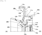
- Fig. 9 shows Example 7 which is not part of the present invention.
- the configuration of a sealing device according to the present Example is similar to that of the sealing device 100b according to Example 3 described above, but is different from that of the case of Example 3 in that the guide made of resin is provided in the bumper portion provided in the rubber-like elastic body portion 120b. Consequently, hereinbelow, only the configuration different from that of the case of Example 3 will be described. Note that the same constituent parts as those of the sealing device 100b according to Example 3 are designated by the same reference numerals as those in Example 3, and the description thereof will be omitted.
- Fig. 9 is a cross-sectional view of the sealing device according to Example 7 of the present invention.
- Fig. 9 shows a cross section of the sealing device obtained by cutting by using the plane including the central axis in the sealing device.
- a sealing device 100f according to the present Example also plays the role in sealing the annular gap between the shaft and the housing 300b.
- the right side in the drawing corresponds to the sealed area side (O) in which the target liquid to be sealed is sealed
- the left side in the drawing corresponds to the air side (A) opposite to the sealed area when the sealing device 100f is used.
- the shaft is not shown, and the housing 300b is depicted by using a dotted line.
- the sealing device 100f according to the present Example includes the metal reinforcing ring 110a, the seal main body 120a made of the rubber-like elastic body that is provided integrally with the reinforcing ring 110a, and the auxiliary reinforcing ring 110b that is fixed to the reinforcing ring 110a by fitting.
- the configurations of the reinforcing ring 110a and the seal main body 120a are the same as those of the case of Example 3 described above.
- the configuration of the auxiliary reinforcing ring 110b is basically the same as that of the case of Example 3 described above, but the configuration related to the bumper portion of the rubber-like elastic body portion 120b is different from that of the case of Example 3. Consequently, hereinbelow, only the configuration different from that of the case of Example 3 will be described.
- the rubber-like elastic body portion 120b integrally has the side lip 123b and a bumper portion 125f.
- the bumper portion 125f is provided in the vicinity of the tip of the inward flange portion 112b, and plays the role in reducing the impact that the dust lip 122a receives from the shaft when the shaft is inserted into the sealing device 100f.
- the bumper portion 125f is constituted by the lip-shaped part that extends from the position located inwardly of the tip of the inward flange portion 112b in the radial direction to the air side (A) outwardly in the radial direction.
- the guide 127 made of PTFE is provided on the inner peripheral side and the air side (A) of the bumper portion 125f.
- the guide 127 is bonded to the bumper portion 125f, and is constituted by the inner peripheral portion 127A that covers the inner peripheral side of the bumper portion 125f and the radial portion 127B that covers the air side (A) of the bumper portion 125f (the air side (A) in the lip-shaped part) .
- the dimensional relationship among the inner diameter of the tip of the guide 127 on the inner peripheral side, the outer diameter of the large diameter portion 220 of the shaft 200, and the inner diameter of the part having the largest inner diameter in the portion that connects the main lip 121a and the dust lip 122a is the same as that of the case of Example 5 or 6 described above.
- the inner peripheral side of the lip-shaped part in the bumper portion 125f that extends to the air side (A) and outwardly in the radial direction is covered with the inner peripheral portion 127A of the guide 127, and the air side (A) of the lip-shaped part is covered with the radial portion 127B of the guide 127.
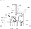
- Fig. 10 shows Example 8 which is not part of the present invention.
- the configuration of a sealing device according to the present Example is similar to that of the sealing device 100c according to Example 4 described above, but is different from that of the case of Example 4 in that the guide made of resin is provided in the bumper portion provided in the rubber-like elastic body portion 120c. Consequently, hereinbelow, only the configuration different from that of the case of Example 4 will be described. Note that the same constituent parts as those of the sealing device 100c according to Example 4 are designated by the same reference numerals as those in Example 4, and the description thereof will be omitted.
- Fig. 10 is a schematic cross-sectional view of the sealing device according to Example 8 which is not part of the present invention.
- Fig. 10 shows a cross section of the sealing device obtained by cutting by using the plane including the central axis in the sealing device.
- a sealing device 100g according to the present Example also plays the role in sealing the annular gap between the shaft and the housing 300b.
- the right side in the drawing corresponds to the sealed area side (O) in which the target liquid to be sealed is sealed
- the left side in the drawing corresponds to the air side (A) opposite to the sealed area when the sealing device 100g is used.
- the shaft is not shown, and the housing 300b is depicted by using a dotted line.
- the sealing device 100g according to the present Example includes the metal reinforcing ring 110a, the seal main body 120a, the auxiliary reinforcing ring 110b, and a rubber-like elastic body portion 120g that is provided in the auxiliary reinforcing ring 110b.
- the configurations of the reinforcing ring 110a, the seal main body 120a, and the auxiliary reinforcing ring 110b are the same as those of the case of Example 4 described above.
- the configuration of the rubber-like elastic body portion 120g is basically the same as that of the rubber-like elastic body portion 120c in Example 4 described above, but the configuration related to the bumper portion is different from that of the case of Example 4. Consequently, hereinbelow, only the configuration different from that of the case of Example 4 will be described.
- a thick portion 120gA is provided on the air side (A) of the inward flange portion 112b.
- the inner peripheral portion of the thick portion 120gA is constituted by a bumper portion 125g and, further, the guide 127 made of PTFE is provided on the inner peripheral side and the air side (A) of the bumper portion 125g.
- the guide 127 is bonded to the rubber-like elastic body portion 120g, and is constituted by the inner peripheral portion 127A that covers the inner peripheral side of the bumper portion 125g, and the radial portion 127B that covers the air side (A) of the bumper portion 125g.
- the radial portion 127B also covers the air side (A) of the thick portion 120gA of the rubber-like elastic body portion 120g.
- the dimensional relationship among the inner diameter of the tip of the guide 127 on the inner peripheral side, the outer diameter of the large diameter portion 220 of the shaft 200, and the inner diameter of the part having the largest inner diameter in the portion that connects the main lip 121a and the dust lip 122a is the same as that of the case of each of Examples 5 to 7 described above.
- the air side (A) of the thick portion 120gA of the rubber-like elastic body portion 120g is also covered with the radial portion 127B of the guide 127.
- the metal slinger may be mounted to the shaft similarly to the case of Example 1 described above, and the side lip 123b in each sealing device may be configured to slidably come into contact with the outward flange portion in the slinger. With this, even in the environment in which muddy water or the like splashes, it is possible to prevent the intrusion of the foreign object to the sealed area side (O).
- the bumper portion for reducing the impact that the dust lip receives from the inserted shaft is provided.
- a guide for guiding the inserted shaft in the direction in which the central axis of the shaft matches the central axis of the sealing device is provided instead of the bumper portion.
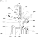
- Figs. 11 , 12 , and 13 are schematic cross-sectional views of sealing devices according to Reference Examples 1, 2, and 3, respectively. Note that each of Figs. 11 to 13 shows a cross section of the sealing device obtained by cutting by using the plane including the central axis in the sealing device. As shown in each of Figs. 11 to 13 , in the sealing device according to each of Reference Examples as well, similarly to the case of each of Examples described above, the right side in the drawing corresponds to the sealed area side (O) in which the target liquid to be sealed is sealed, and the left side in the drawing corresponds to the air side (A) opposite to the sealed area when the sealing device is used.
- O sealed area side
- A air side
- the sealing device according to each of Reference Examples also includes the metal reinforcing ring 110a and the seal main body 120a made of the rubber-like elastic body that is provided integrally with the reinforcing ring 110a.
- each of Reference Examples includes the guide for guiding the inserted shaft instead of the bumper portion.
- Reference Examples will be described sequentially. Note that the same constituent parts as those in Example 3 described above are designated by the same reference numerals as those in Example 3, and the description thereof will be omitted.
- a sealing device 100h according to Reference Example 1 includes an auxiliary reinforcing ring 110h that is fixed to the reinforcing ring 110a by fitting.
- the auxiliary reinforcing ring 110h includes a cylindrical portion 111h that is fitted in the inner peripheral surface of the fitting portion 113a of the reinforcing ring 110a, and a flange portion 112h that extends from the end portion of the cylindrical portion 111h on the sealed area side (O) inwardly in the radial direction.
- the side lip 123b that extends from the tip of the flange portion 112h to the air side (A) is provided integrally with the auxiliary reinforcing ring 110h.
- the sealing device 100h includes a guide 140h that is fixed to the reinforcing ring 110a by fitting.
- the annular guide 140h includes a cylindrical portion 141h that is fitted in the inner peripheral surface of the cylindrical portion 111a of the reinforcing ring 110a, and a flange portion 142h that extends from the end portion of the cylindrical portion 141h on the air side (A) inwardly in the radial direction.
- the guide 140h includes a cylindrical portion 143h that extends from the tip of the flange portion 142h on the inner peripheral side to the air side (A), and an increased diameter portion 144h that extends from the end portion of the cylindrical portion 143h on the air side (A) to the air side (A) while increasing its diameter.
- the inner diameter of the cylindrical portion 143h is set to be larger than the outer diameter Y1 of the large diameter portion 220 of the shaft 200 (see Fig. 2 ).
- a tapered surface 145h of which the diameter is increased with approach to the air side (A) is formed.
- the tip of the shaft 200 hits the inner peripheral surface of the increased diameter portion 144h.
- the inserted shaft 200 is guided in the direction in which the central axis of the shaft 200 matches the central axis of the sealing device 100h.
- the tip of the shaft 200 is prevented from hitting the dust lip 122a and the main lip 121a, and hence the turnover of the dust lip 122a and the damage to the dust lip 122a and the main lip 121a are prevented.
- sealing device 100 since the tapered surface 145h of which the diameter is increased with approach to the air side (A) is formed at the end portion of the increased diameter portion 144h on the air side (A), the inserted shaft 200 is smoothly guided in the direction in which the central axis thereof matches the central axis of the sealing device 100h.
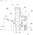
- Fig. 12 shows a sealing device 100i according to Reference Example 2 which is not part of the present invention.
- the shape of the guide is different from that in Reference Example 1 described above.
- the sealing device 100i includes a guide 140i that is fixed to the reinforcing ring 110a by the auxiliary reinforcing ring 110h.
- the annular guide 140i includes a radial portion 141i having an outer diameter substantially equal to the inner diameter of the fitting portion 113a of the reinforcing ring 110a, and is fixed so as to be positioned in an axial direction and the radial direction by being held between the reinforcing ring 110a and the auxiliary reinforcing ring 110h fitted in the reinforcing ring 110a in a state in which the annular guide 140i is accommodated in the fitting portion 113a.
- the guide 140i includes a curved portion 142i that is curved from the tip of the radial portion 141i on the inner peripheral side to the air side (A), and a radial portion 143i that extends from the end portion of the curved portion 142i on the air side (A) inwardly in the radial direction.
- the inner diameter of the radial portion 143i is set to be larger than the outer diameter Y1 of the large diameter portion 220 of the shaft 200 (see Fig. 2 ) . Consequently, even when the position of the shaft 200 is displaced in the radial direction at the time of insertion of the shaft 200 into the sealing device 100i, the tip of the shaft 200 comes into contact with the radial portion 143i.
- the inserted shaft 200 is guided in the direction in which the central axis thereof matches the central axis of the sealing device 100i.
- the sealing device 100i it is possible to obtain the same effects as those of the case of Reference Example 1 described above.
- the tapered surface of which the diameter is increased with approach to the air side (A) may also be formed at the end portion of the radial portion 143i on the inner peripheral side.
- Fig. 13 shows a sealing device 100j according to Reference Example 3 which is not part of the present invention.
- the shape of the guide is different from that in each Reference Example described above, and the auxiliary reinforcing ring is not provided.
- the sealing device 100j includes a guide 140j that is fixed to the reinforcing ring 110a by fitting.
- the annular guide 140j includes an outer peripheral surface 141j that is fitted in the inner peripheral surface of the fitting portion 113a of the reinforcing ring 110a.
- the guide 140j includes an inner peripheral surface 142j having an inner diameter larger than the outer diameter Y1 of the large diameter portion 220 of the shaft 200 (see Fig.
- the metal slinger may be mounted to the shaft similarly to the case of Example 1 described above, and the side lip 123b in each sealing device may be configured to slidably come into contact with the outward flange portion in the slinger. With this, even in the environment in which muddy water or the like splashes, it is possible to prevent the intrusion of the foreign object to the sealed area side (O).
Landscapes
- Engineering & Computer Science (AREA)
- General Engineering & Computer Science (AREA)
- Mechanical Engineering (AREA)
- Physics & Mathematics (AREA)
- Fluid Mechanics (AREA)
- Sealing With Elastic Sealing Lips (AREA)
- Sealing Devices (AREA)
Applications Claiming Priority (3)
| Application Number | Priority Date | Filing Date | Title |
|---|---|---|---|
| JP2014104302 | 2014-05-20 | ||
| JP2014171784 | 2014-08-26 | ||
| PCT/JP2015/063971 WO2015178292A1 (ja) | 2014-05-20 | 2015-05-15 | 密封装置 |
Publications (4)
| Publication Number | Publication Date |
|---|---|
| EP3147544A1 EP3147544A1 (en) | 2017-03-29 |
| EP3147544A4 EP3147544A4 (en) | 2018-02-28 |
| EP3147544C0 EP3147544C0 (en) | 2024-10-23 |
| EP3147544B1 true EP3147544B1 (en) | 2024-10-23 |
Family
ID=54553964
Family Applications (1)
| Application Number | Title | Priority Date | Filing Date |
|---|---|---|---|
| EP15796984.1A Active EP3147544B1 (en) | 2014-05-20 | 2015-05-15 | Sealing device |
Country Status (6)
| Country | Link |
|---|---|
| US (1) | US10208861B2 (ja) |
| EP (1) | EP3147544B1 (ja) |
| JP (1) | JP5971450B2 (ja) |
| KR (1) | KR101861470B1 (ja) |
| CN (1) | CN106461085B (ja) |
| WO (1) | WO2015178292A1 (ja) |
Families Citing this family (13)
| Publication number | Priority date | Publication date | Assignee | Title |
|---|---|---|---|---|
| JP6374961B2 (ja) | 2014-06-10 | 2018-08-15 | Nok株式会社 | 密封装置 |
| KR102037705B1 (ko) * | 2015-09-03 | 2019-10-29 | 엔오케이 가부시키가이샤 | 밀봉구조 |
| USD802104S1 (en) * | 2015-09-25 | 2017-11-07 | Nok Corporation | Seal |
| JP6921491B2 (ja) * | 2016-09-20 | 2021-08-18 | Nok株式会社 | 密封装置 |
| EP3607229B1 (en) * | 2017-04-07 | 2021-12-22 | Dana Automotive Systems Group, LLC | Sealing member with integrally formed ribs |
| US20190226584A1 (en) * | 2018-01-19 | 2019-07-25 | American Axle & Manufacturing, Inc. | Lip seal with air-side spring |
| CN112204278B (zh) * | 2018-07-09 | 2023-02-17 | Nok株式会社 | 密封装置 |
| JP7441849B2 (ja) * | 2019-09-30 | 2024-03-01 | Nok株式会社 | 密封装置 |
| US11454259B2 (en) * | 2020-01-23 | 2022-09-27 | DRiV Automotive Inc. | Hydraulic assembly |
| CN112483740A (zh) * | 2020-11-26 | 2021-03-12 | 江西爱森德实业有限公司 | 一种节流承插式无垫连接管材 |
| US12578018B2 (en) | 2021-10-26 | 2026-03-17 | Nok Corporation | Steering dust seal and sealing device |
| US20240421659A1 (en) * | 2023-06-14 | 2024-12-19 | Borgwarner Inc. | Rotating machine and drive module assembly including the same |
| CN117030256B (zh) * | 2023-08-18 | 2024-04-19 | 南通市嘉诚机械有限公司 | 一种汽车轴承部件用密封式测试装置 |
Citations (3)
| Publication number | Priority date | Publication date | Assignee | Title |
|---|---|---|---|---|
| US4550920A (en) * | 1984-05-17 | 1985-11-05 | Nippon Oil Seal Industry Co., Ltd. | Oil seal with main lip, subsidiary lip and dust lip |
| JP2001165326A (ja) * | 1999-12-06 | 2001-06-22 | Nok Corp | 密封装置 |
| US20100327538A1 (en) * | 2008-02-05 | 2010-12-30 | Yoshitaka Okaji | Bearing seal and mold assembly for forming such bearing seal |
Family Cites Families (21)
| Publication number | Priority date | Publication date | Assignee | Title |
|---|---|---|---|---|
| JPS5751870U (ja) * | 1980-09-09 | 1982-03-25 | ||
| JPH0511405Y2 (ja) * | 1986-02-21 | 1993-03-22 | ||
| JPH04128576A (ja) | 1990-09-17 | 1992-04-30 | Matsushita Refrig Co Ltd | 密閉型電動圧縮機の電装部品保護装置 |
| JPH04128576U (ja) | 1991-05-20 | 1992-11-24 | エヌオーケー株式会社 | オイルシール |
| CA2114818A1 (en) | 1993-07-19 | 1995-01-20 | David E. Beth | Oscillating spindle sander |
| JP2599517Y2 (ja) | 1993-11-17 | 1999-09-13 | エヌオーケー株式会社 | 密封装置 |
| JP3359462B2 (ja) | 1995-03-14 | 2002-12-24 | エヌオーケー株式会社 | 密封装置 |
| JP3581969B2 (ja) * | 1995-06-16 | 2004-10-27 | Nok株式会社 | 密封装置 |
| US5577741A (en) * | 1995-07-17 | 1996-11-26 | Brenco Incorporated | Combination lip and sleeve seal and its method of manufacture |
| JP3893761B2 (ja) * | 1998-07-22 | 2007-03-14 | Nok株式会社 | 密封装置 |
| US6325187B1 (en) * | 1999-05-12 | 2001-12-04 | Tenneco Automotive Inc. | Dirt wiper system for suspension damper |
| JP2002188730A (ja) * | 2000-12-25 | 2002-07-05 | Showa Corp | 往復動用オイルシールのダストリップ構造 |
| JP2003014135A (ja) | 2001-06-29 | 2003-01-15 | Nok Corp | 密封装置 |
| JP2004301161A (ja) * | 2003-03-28 | 2004-10-28 | Kayaba Ind Co Ltd | ストラット型ショックアブソーバ |
| JP2005233218A (ja) * | 2004-02-17 | 2005-09-02 | Nok Corp | 密封装置 |
| JP2008111509A (ja) | 2006-10-31 | 2008-05-15 | Nok Corp | オイルシール |
| JP5209940B2 (ja) * | 2007-11-13 | 2013-06-12 | カヤバ工業株式会社 | 高摩擦流体シール及び緩衝器 |
| CN201884661U (zh) * | 2010-12-19 | 2011-06-29 | 揭阳市天诚密封件有限公司 | 后端盖组合式油封 |
| JP5702676B2 (ja) * | 2011-06-22 | 2015-04-15 | カヤバ工業株式会社 | オイルシール |
| DE102012016559A1 (de) * | 2012-08-22 | 2014-02-27 | Carl Freudenberg Kg | Dichtungsanordnung und Protektorring |
| US9863464B2 (en) * | 2014-10-22 | 2018-01-09 | Nok Corporation | Dust cover |
-
2015
- 2015-05-15 US US15/311,926 patent/US10208861B2/en active Active
- 2015-05-15 KR KR1020167031799A patent/KR101861470B1/ko active Active
- 2015-05-15 WO PCT/JP2015/063971 patent/WO2015178292A1/ja not_active Ceased
- 2015-05-15 EP EP15796984.1A patent/EP3147544B1/en active Active
- 2015-05-15 CN CN201580025477.8A patent/CN106461085B/zh active Active
- 2015-05-15 JP JP2016521066A patent/JP5971450B2/ja active Active
Patent Citations (3)
| Publication number | Priority date | Publication date | Assignee | Title |
|---|---|---|---|---|
| US4550920A (en) * | 1984-05-17 | 1985-11-05 | Nippon Oil Seal Industry Co., Ltd. | Oil seal with main lip, subsidiary lip and dust lip |
| JP2001165326A (ja) * | 1999-12-06 | 2001-06-22 | Nok Corp | 密封装置 |
| US20100327538A1 (en) * | 2008-02-05 | 2010-12-30 | Yoshitaka Okaji | Bearing seal and mold assembly for forming such bearing seal |
Also Published As
| Publication number | Publication date |
|---|---|
| JP5971450B2 (ja) | 2016-08-17 |
| US10208861B2 (en) | 2019-02-19 |
| EP3147544A1 (en) | 2017-03-29 |
| EP3147544A4 (en) | 2018-02-28 |
| CN106461085A (zh) | 2017-02-22 |
| KR20160145136A (ko) | 2016-12-19 |
| EP3147544C0 (en) | 2024-10-23 |
| CN106461085B (zh) | 2018-06-22 |
| US20170122438A1 (en) | 2017-05-04 |
| KR101861470B1 (ko) | 2018-05-28 |
| WO2015178292A1 (ja) | 2015-11-26 |
| JPWO2015178292A1 (ja) | 2017-04-20 |
Similar Documents
| Publication | Publication Date | Title |
|---|---|---|
| EP3147544B1 (en) | Sealing device | |
| JP4924789B2 (ja) | 密封装置 | |
| CA2759014C (en) | A sealed hub-bearing assembly for agricultural applications | |
| EP2128501B1 (en) | Hermetic sealing device | |
| EP3184864B1 (en) | Sealing structure | |
| CN102016365A (zh) | 密封装置 | |
| EP2799743A1 (en) | Sealing device | |
| CN114635915B (zh) | 密封装置 | |
| KR20160111959A (ko) | 시일이 형성된 구름 베어링 | |
| EP3048337A1 (en) | Seal for ball-screw device | |
| CA2978105C (en) | Sealing device | |
| KR20070089141A (ko) | 밀봉장치 | |
| EP3845786A1 (en) | Sealing device | |
| JP2018529050A (ja) | 保護リング、シール構造、およびジャーナルクロス組立体 | |
| US11835136B2 (en) | Sealing device | |
| KR101411611B1 (ko) | 실링 캡 및 이를 이용한 휠 베어링 조립체 | |
| JP2017089801A (ja) | デフサイド用の密封装置 | |
| KR101966197B1 (ko) | 클러치 릴리즈 베어링 | |
| EP3273118B1 (en) | Sealing device | |
| JP2022048505A (ja) | オイルシール | |
| CN112013115B (zh) | 密封装置 | |
| JP2017089803A (ja) | 密封装置 | |
| JP2003106463A (ja) | 密封装置 | |
| JP2010112481A (ja) | オイルシール | |
| JP2018105323A (ja) | 密封装置 |
Legal Events
| Date | Code | Title | Description |
|---|---|---|---|
| STAA | Information on the status of an ep patent application or granted ep patent |
Free format text: STATUS: THE INTERNATIONAL PUBLICATION HAS BEEN MADE |
|
| PUAI | Public reference made under article 153(3) epc to a published international application that has entered the european phase |
Free format text: ORIGINAL CODE: 0009012 |
|
| STAA | Information on the status of an ep patent application or granted ep patent |
Free format text: STATUS: REQUEST FOR EXAMINATION WAS MADE |
|
| 17P | Request for examination filed |
Effective date: 20161128 |
|
| AK | Designated contracting states |
Kind code of ref document: A1 Designated state(s): AL AT BE BG CH CY CZ DE DK EE ES FI FR GB GR HR HU IE IS IT LI LT LU LV MC MK MT NL NO PL PT RO RS SE SI SK SM TR |
|
| AX | Request for extension of the european patent |
Extension state: BA ME |
|
| DAV | Request for validation of the european patent (deleted) | ||
| DAX | Request for extension of the european patent (deleted) | ||
| A4 | Supplementary search report drawn up and despatched |
Effective date: 20180129 |
|
| RIC1 | Information provided on ipc code assigned before grant |
Ipc: F16J 15/3252 20160101ALI20180123BHEP Ipc: F16J 15/32 20160101AFI20180123BHEP Ipc: F16J 15/3276 20160101ALI20180123BHEP Ipc: F16J 15/322 20160101ALI20180123BHEP Ipc: F16J 15/3224 20160101ALI20180123BHEP Ipc: F16J 15/3244 20160101ALI20180123BHEP |
|
| STAA | Information on the status of an ep patent application or granted ep patent |
Free format text: STATUS: EXAMINATION IS IN PROGRESS |
|
| 17Q | First examination report despatched |
Effective date: 20191008 |
|
| REG | Reference to a national code |
Ref country code: DE Ref legal event code: R079 Free format text: PREVIOUS MAIN CLASS: F16J0015320000 Ipc: F16J0015323200 Ref country code: DE Ref legal event code: R079 Ref document number: 602015090211 Country of ref document: DE Free format text: PREVIOUS MAIN CLASS: F16J0015320000 Ipc: F16J0015323200 |
|
| RIC1 | Information provided on ipc code assigned before grant |
Ipc: F16J 15/32 20060101ALI20240410BHEP Ipc: F16J 15/3276 20160101ALI20240410BHEP Ipc: F16J 15/3252 20160101ALI20240410BHEP Ipc: F16J 15/3244 20160101ALI20240410BHEP Ipc: F16J 15/3224 20160101ALI20240410BHEP Ipc: F16J 15/3232 20160101AFI20240410BHEP |
|
| GRAP | Despatch of communication of intention to grant a patent |
Free format text: ORIGINAL CODE: EPIDOSNIGR1 |
|
| STAA | Information on the status of an ep patent application or granted ep patent |
Free format text: STATUS: GRANT OF PATENT IS INTENDED |
|
| INTG | Intention to grant announced |
Effective date: 20240527 |
|
| GRAS | Grant fee paid |
Free format text: ORIGINAL CODE: EPIDOSNIGR3 |
|
| GRAA | (expected) grant |
Free format text: ORIGINAL CODE: 0009210 |
|
| STAA | Information on the status of an ep patent application or granted ep patent |
Free format text: STATUS: THE PATENT HAS BEEN GRANTED |
|
| AK | Designated contracting states |
Kind code of ref document: B1 Designated state(s): AL AT BE BG CH CY CZ DE DK EE ES FI FR GB GR HR HU IE IS IT LI LT LU LV MC MK MT NL NO PL PT RO RS SE SI SK SM TR |
|
| REG | Reference to a national code |
Ref country code: GB Ref legal event code: FG4D |
|
| REG | Reference to a national code |
Ref country code: CH Ref legal event code: EP |
|
| REG | Reference to a national code |
Ref country code: DE Ref legal event code: R096 Ref document number: 602015090211 Country of ref document: DE |
|
| REG | Reference to a national code |
Ref country code: IE Ref legal event code: FG4D |
|
| U01 | Request for unitary effect filed |
Effective date: 20241115 |
|
| U07 | Unitary effect registered |
Designated state(s): AT BE BG DE DK EE FI FR IT LT LU LV MT NL PT RO SE SI Effective date: 20241125 |
|
| PG25 | Lapsed in a contracting state [announced via postgrant information from national office to epo] |
Ref country code: IS Free format text: LAPSE BECAUSE OF FAILURE TO SUBMIT A TRANSLATION OF THE DESCRIPTION OR TO PAY THE FEE WITHIN THE PRESCRIBED TIME-LIMIT Effective date: 20250223 Ref country code: HR Free format text: LAPSE BECAUSE OF FAILURE TO SUBMIT A TRANSLATION OF THE DESCRIPTION OR TO PAY THE FEE WITHIN THE PRESCRIBED TIME-LIMIT Effective date: 20241023 |
|
| PG25 | Lapsed in a contracting state [announced via postgrant information from national office to epo] |
Ref country code: ES Free format text: LAPSE BECAUSE OF FAILURE TO SUBMIT A TRANSLATION OF THE DESCRIPTION OR TO PAY THE FEE WITHIN THE PRESCRIBED TIME-LIMIT Effective date: 20241023 |
|
| PG25 | Lapsed in a contracting state [announced via postgrant information from national office to epo] |
Ref country code: NO Free format text: LAPSE BECAUSE OF FAILURE TO SUBMIT A TRANSLATION OF THE DESCRIPTION OR TO PAY THE FEE WITHIN THE PRESCRIBED TIME-LIMIT Effective date: 20250123 |
|
| PG25 | Lapsed in a contracting state [announced via postgrant information from national office to epo] |
Ref country code: GR Free format text: LAPSE BECAUSE OF FAILURE TO SUBMIT A TRANSLATION OF THE DESCRIPTION OR TO PAY THE FEE WITHIN THE PRESCRIBED TIME-LIMIT Effective date: 20250124 |
|
| PG25 | Lapsed in a contracting state [announced via postgrant information from national office to epo] |
Ref country code: PL Free format text: LAPSE BECAUSE OF FAILURE TO SUBMIT A TRANSLATION OF THE DESCRIPTION OR TO PAY THE FEE WITHIN THE PRESCRIBED TIME-LIMIT Effective date: 20241023 |
|
| PGFP | Annual fee paid to national office [announced via postgrant information from national office to epo] |
Ref country code: GB Payment date: 20250327 Year of fee payment: 11 |
|
| PG25 | Lapsed in a contracting state [announced via postgrant information from national office to epo] |
Ref country code: RS Free format text: LAPSE BECAUSE OF FAILURE TO SUBMIT A TRANSLATION OF THE DESCRIPTION OR TO PAY THE FEE WITHIN THE PRESCRIBED TIME-LIMIT Effective date: 20250123 |
|
| U20 | Renewal fee for the european patent with unitary effect paid |
Year of fee payment: 11 Effective date: 20250407 |
|
| PG25 | Lapsed in a contracting state [announced via postgrant information from national office to epo] |
Ref country code: SM Free format text: LAPSE BECAUSE OF FAILURE TO SUBMIT A TRANSLATION OF THE DESCRIPTION OR TO PAY THE FEE WITHIN THE PRESCRIBED TIME-LIMIT Effective date: 20241023 |
|
| PG25 | Lapsed in a contracting state [announced via postgrant information from national office to epo] |
Ref country code: SK Free format text: LAPSE BECAUSE OF FAILURE TO SUBMIT A TRANSLATION OF THE DESCRIPTION OR TO PAY THE FEE WITHIN THE PRESCRIBED TIME-LIMIT Effective date: 20241023 |
|
| PG25 | Lapsed in a contracting state [announced via postgrant information from national office to epo] |
Ref country code: CZ Free format text: LAPSE BECAUSE OF FAILURE TO SUBMIT A TRANSLATION OF THE DESCRIPTION OR TO PAY THE FEE WITHIN THE PRESCRIBED TIME-LIMIT Effective date: 20241023 |
|
| PLBE | No opposition filed within time limit |
Free format text: ORIGINAL CODE: 0009261 |
|
| STAA | Information on the status of an ep patent application or granted ep patent |
Free format text: STATUS: NO OPPOSITION FILED WITHIN TIME LIMIT |
|
| 26N | No opposition filed |
Effective date: 20250724 |
|
| REG | Reference to a national code |
Ref country code: CH Ref legal event code: H13 Free format text: ST27 STATUS EVENT CODE: U-0-0-H10-H13 (AS PROVIDED BY THE NATIONAL OFFICE) Effective date: 20251223 |
|
| PG25 | Lapsed in a contracting state [announced via postgrant information from national office to epo] |
Ref country code: CH Free format text: LAPSE BECAUSE OF NON-PAYMENT OF DUE FEES Effective date: 20250531 |
|
| PG25 | Lapsed in a contracting state [announced via postgrant information from national office to epo] |
Ref country code: MC Free format text: LAPSE BECAUSE OF FAILURE TO SUBMIT A TRANSLATION OF THE DESCRIPTION OR TO PAY THE FEE WITHIN THE PRESCRIBED TIME-LIMIT Effective date: 20241023 |
|
| PG25 | Lapsed in a contracting state [announced via postgrant information from national office to epo] |
Ref country code: IE Free format text: LAPSE BECAUSE OF NON-PAYMENT OF DUE FEES Effective date: 20250515 |