EP3147597B1 - Eisaufbewahrungsvorrichtung und kühlschrank - Google Patents
Eisaufbewahrungsvorrichtung und kühlschrank Download PDFInfo
- Publication number
- EP3147597B1 EP3147597B1 EP15880803.0A EP15880803A EP3147597B1 EP 3147597 B1 EP3147597 B1 EP 3147597B1 EP 15880803 A EP15880803 A EP 15880803A EP 3147597 B1 EP3147597 B1 EP 3147597B1
- Authority
- EP
- European Patent Office
- Prior art keywords
- ice
- stirring
- ice storage
- storage device
- rotating shaft
- Prior art date
- Legal status (The legal status is an assumption and is not a legal conclusion. Google has not performed a legal analysis and makes no representation as to the accuracy of the status listed.)
- Active
Links
Images


Classifications
-
- F—MECHANICAL ENGINEERING; LIGHTING; HEATING; WEAPONS; BLASTING
- F25—REFRIGERATION OR COOLING; COMBINED HEATING AND REFRIGERATION SYSTEMS; HEAT PUMP SYSTEMS; MANUFACTURE OR STORAGE OF ICE; LIQUEFACTION SOLIDIFICATION OF GASES
- F25C—PRODUCING, WORKING OR HANDLING ICE
- F25C5/00—Working or handling ice
- F25C5/02—Apparatus for disintegrating, removing or harvesting ice
- F25C5/04—Apparatus for disintegrating, removing or harvesting ice without the use of saws
- F25C5/046—Ice-crusher machines
-
- F—MECHANICAL ENGINEERING; LIGHTING; HEATING; WEAPONS; BLASTING
- F25—REFRIGERATION OR COOLING; COMBINED HEATING AND REFRIGERATION SYSTEMS; HEAT PUMP SYSTEMS; MANUFACTURE OR STORAGE OF ICE; LIQUEFACTION SOLIDIFICATION OF GASES
- F25C—PRODUCING, WORKING OR HANDLING ICE
- F25C5/00—Working or handling ice
- F25C5/20—Distributing ice
- F25C5/24—Distributing ice for storing bins
-
- F—MECHANICAL ENGINEERING; LIGHTING; HEATING; WEAPONS; BLASTING
- F25—REFRIGERATION OR COOLING; COMBINED HEATING AND REFRIGERATION SYSTEMS; HEAT PUMP SYSTEMS; MANUFACTURE OR STORAGE OF ICE; LIQUEFACTION SOLIDIFICATION OF GASES
- F25C—PRODUCING, WORKING OR HANDLING ICE
- F25C2500/00—Problems to be solved
- F25C2500/02—Geometry problems
-
- F—MECHANICAL ENGINEERING; LIGHTING; HEATING; WEAPONS; BLASTING
- F25—REFRIGERATION OR COOLING; COMBINED HEATING AND REFRIGERATION SYSTEMS; HEAT PUMP SYSTEMS; MANUFACTURE OR STORAGE OF ICE; LIQUEFACTION SOLIDIFICATION OF GASES
- F25C—PRODUCING, WORKING OR HANDLING ICE
- F25C5/00—Working or handling ice
- F25C5/20—Distributing ice
- F25C5/22—Distributing ice particularly adapted for household refrigerators
Definitions
- the present invention relates to the technical field of household appliances, and in particular to an ice storage device and a refrigerator.
- an automatic ice maker includes an ice making device, an ice storage device, etc.
- the ice making device stores the obtained ice cubes into the ice storage device, and then consumers take some ice cubes from the ice storage device as needed.
- An existing ice storage device primarily consists of an ice storage box and an ice crushing device.
- the ice crushing device is located within the ice storage box, and mainly includes at least one fixed ice crushing blade, at least one moving ice crushing blade and a rotating shaft.
- Each moving ice crushing blade rotates synchronously to the rotating shaft.
- the moving ice crushing blade may crush ice cubes and discharge them from the ice storage box.
- the moving ice crushing blade may stir and squeeze ice cubes so that ice cubes force the ice discharging door to open and then discharge from the ice storage box.
- the refrigerator includes a body, a storage compartment provided in the body, a door to open and close the storage compartment, and icemaker provided to one side of the storage compartment, and ice bucket provided under the icemaker, and a crusher provided to the rear surface of the door and having an inlet disposed under the outlet of the ice bucket when the door is closed.
- the refrigerator includes a cabinet defining a storage compartment; a door configured to open and close the storage compartment, the door comprising an outer case and a door liner; an ice maker configured to generate ice cubes; an ice bin provided at the refrigerator door, the ice bin storing the ice cubes generated in the ice maker; a dispenser provided at the door, the dispenser dispensing the ice cubes stored in the ice bin; and a vacuum insulation panel disposed between the outer case and the ice bin to insulate the storage compartment from an outside.
- One embodiment of the present invention provides an ice storage device and a refrigerator, which may solve the problem of low discharge rate of ice cubes.
- the embodiment of the present invention employs the following technical solution:
- At least one stirrer is sleeved on said rotating shaft and rotates synchronously to the rotating shaft, said stirrer includes a columnar stirring body having at least one stirring finger on its columnar outer surface, said stirring finger is arranged obliquely or perpendicular to an axial direction of said rotating shaft, and a gap is maintained between the tip of said stirring finger and said ice discharging door.
- At least two of said at least one stirring finger are uniformly arranged along the circumference of said stirring body.
- said stirring finger includes a first stirring portion and a second stirring portion, one end of said first stirring portion is fixedly connected to the columnar outer surface of said stirring body and the other end thereof is connected to said second stirring portion, and said second stirring portion is arranged obliquely or perpendicular to said first stirring portion.
- an elastic element is provided between said ice discharging door and said ice storage box.
- said ice discharging door is articulated with said ice storage box.
- At least one reinforced rib is provided on a surface of said ice discharging door facing the interior of said ice storage box.
- said fixed ice crushing blade is located at the position of the outlet of said ice storage box, with one end of the fixed ice crushing blade being fixedly connected
- said fixed ice crushing blade has a first ice crushing face and a first backside which are arranged away from and oppositely to each other, with said first ice crushing face being away from the outlet of said ice storage box and having first ice crushing teeth, and said first backside facing the outlet of said ice crushing box.
- said moving ice crushing blade has a second ice crushing face and a second backside which are axially parallel to said rotating shaft and are arranged away from each other; and said moving ice crushing blade moves toward said fixed ice crushing blade, and during the ice crushing, said second ice crushing face faces said first ice crushing face, and said second ice crushing face has second ice crushing teeth; and said second backside is planar.
- said stirring finger is configured to, when said driving device drives said rotating shaft rotate in a second direction opposed to the first direction, push ice cubes to move toward said fixed ice crushing blade.
- said at least one stirrer comprises two or more stirrers, and when two stirrers are mounted, the two stirrers are placed at both ends of the rotating shaft inside the ice storage box, and all ice crushing blades are mounted between the two stirrers; and when three or more stirrers are mounted, the stirrers and the ice crushing blades are alternately arranged.
- a stirrer specially designed to facilitate the opening of an ice discharging door is provided inside the ice storage box, a rotating shaft is driven to rotate by a driving device (for example, a motor), the rotating shaft in turn drives the stirring body to rotate, the stirring body further drives the stirring finger to rotate, and the stirring finger pushes large ice cubes or entire ice cubes so that the ice discharging door is forced to open by the pushing of ice cubes.
- a driving device for example, a motor
- the rotating shaft drives the stirring body to rotate
- the stirring body further drives the stirring finger to rotate
- the stirring finger pushes large ice cubes or entire ice cubes so that the ice discharging door is forced to open by the pushing of ice cubes.
- a refrigerator includes an ice maker having the ice storage device as described above. An inlet of said ice storage device is communicated to an outlet of said ice maker.
- the refrigerator provided by an embodiment of the present invention, since equipped with the ice storage device as described above, has all advantages of the ice storage device, and will not be repeated herein.
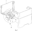
- One embodiment of the present invention provides an ice storage device, as shown in Fig. 1 and Fig. 2 , including an ice storage box 1.
- An ice discharging door 3 is provided at an outlet of the ice storage box 1.
- An ice crushing device is provided inside the ice storage box 1, and the ice crushing device comprises at least one fixed ice crushing blade 4 and at least one moving ice crushing blade 5.
- Each moving ice crushing blade 5 is sleeved on a rotating shaft 6 and both rotate synchronously.
- the rotating shaft 6 is connected to a driving device (for example, a motor) which is configured to drive the rotating shaft 6 to rotate.
- a driving device for example, a motor
- a stirrer 2 is further sleeved on the rotating shaft 6, and the stirrer 2 rotates synchronously to the rotating shaft 6.
- the stirrer 2 includes a columnar stirring body 201 having at least one stirring finger on its columnar outer surface, the stirring finger is arranged obliquely or perpendicular to an axial direction of the rotating shaft 6, and a gap is maintained between the tip of the stirring finger and the ice discharging door 3.
- the expression "the stirring finger is arranged obliquely or perpendicular to an axial direction of the stirring body 201" means that, the stirring finger is not parallel to the axial direction of the stirring body 201, and instead, it is arranged at a certain oblique angle to the axial direction of the stirring body.
- this oblique angle is approximate to (or equal to) 90°
- the stirring finger may be allowed to have a large radial dimension at its tip even with a small (minimal) length. This radial dimension is a radial distance from the axis of the rotating shaft. As a result, the end of the stirring finger gets close to the ice discharging door 3.
- the stirring finger may be allowed to stir more ice cubes, and thus, more ice cubes push the ice discharging door 3 and the pushing force stressed onto the ice discharging door 3 is correspondingly increased. Hence, it is easier to open the ice discharging door 3, and then the discharge rate of ice cubes is improved.
- the stirring body 201 and the rotating shaft 6 are fixedly connected to each other.
- the connection may be realized by interference fit, or the position where the rotating shaft 6 and the stirring body 201 are connected to each other is designed in a special shape.
- the rotating shaft 6 at this position is designed as a flat shaft, and correspondingly the stirring body 201 is designed as a through hole having a flat surface, like a stirring axle hole 204 as shown in Fig. 3 .
- the connection also may be realized by keys, for example, flat keys, splines or the like.
- the gap is maintained between the tip of said stirring finger and the ice discharging door 3 so that the stirring finger may freely rotate around the rotating shaft 6. This gap cannot be too large, or otherwise ice cubes are likely to escape from the ice storage box 1.
- the stirrer 2 designed to facilitate the opening of the ice discharging door 3 is provided inside the ice storage box 1, the rotating shaft 6 is driven to rotate by a driving device (for example, a motor), the rotating shaft 6 in turn drives the stirring body 201 to rotate, the stirring body 201 further drives the at least one stirring finger to rotate, and the at least one stirring finger stirs and pushes some ice cubes toward the ice discharging door 3 so that the ice discharging door 3 is forced to open by the pushing of ice cubes.
- a driving device for example, a motor
- the rotating shaft 6 in turn drives the stirring body 201 to rotate
- the stirring body 201 further drives the at least one stirring finger to rotate
- the at least one stirring finger stirs and pushes some ice cubes toward the ice discharging door 3 so that the ice discharging door 3 is forced to open by the pushing of ice cubes.
- the ice discharging door 3 is forced to open by the pushing of ice cubes.
- At least two said stirring fingers may be uniformly arranged in the circumference of the stirring body 201.
- the stirrer 2 has three said stirring fingers which, having a three-jaw chuck structure, are circumferentially and uniformly distributed on the outer surface of the stirring body 201.
- each stirring finger includes a first stirring portion 202 and a second stirring portion 203.
- One end of the first stirring portion 202 is fixedly connected to the columnar outer surface of the stirring body 201, and the other end thereof is connected to the second stirring portion 203.
- the second stirring portion 203 is arranged obliquely or perpendicular to the first stirring portion 202.
- the arrangement of the second stirring portion 202 may increase the surface area of the tip of the first stirring portion 202, so that the first stirring portion 202 can contact more ice cubes at its tip to thereby stir more ice cubes and increase the pushing force stressed onto the ice discharging door 3. That is, the tip of the first stirring portion 202 may stir more ice cubs so that more ice cubes push the ice discharging door 3, and as a result, it is easier to open the ice discharging door 3. When the ice discharging door 3 is opened, more ice cubes may be taken out, and thus the discharge rate of ice cubes is further improved.
- first stirring portion 202 and the second stirring portion 203 there are many ways of connecting the first stirring portion 202 and the second stirring portion 203.
- the first stirring portion 202 and the second stirring portion 203 form an integrated structure.
- This integrated structure may be produced by powder metallurgy, bending, casting or welding or the like.
- the first stirring portion 202 and the second stirring portion 203 may be fixedly connected in a detachable manner. This fixed connection in a detachable manner may be realized by threading, riveting or the like.
- the second stirring portion 203 is arranged obliquely or perpendicularly to the first stirring portion 202" means that the second stirring portion 203 is arranged at a certain angle with respect to, not in parallel to, the first stirring portion 202.
- the shape, formed after the first stirring portion 202 and the second stirring portion 203 are connected to each other may be similar to an "L" shape or a "T” shape, and will not be specifically defined herein.
- the shape, formed after the first stirring portion 202 and the second stirring portion 203 are connected to each other is similar to the "L" shape, their connection is smooth arc transition, and an included angle between the two stirring portions is not less than 90° .
- the included angle between the two stirring portions When the two stirring portions form the integrated structure by bending, a larger included angle between the two stirring portions indicates a higher strength at the bending position. However, the included angle should not be too large. Of course, the included angle between the two stirring portions may be set to be less than 90°.
- stirrer 2 when the stirrer 2 is mounted at both ends of the rotating shaft 6 or close to the inner surface of the ice storage box 1, it is better to make an end of the second stirring portion 203 which is far away from the stirring body 201 closer to the inner surface of the ice storage box 1 than the other end of the second stirring portion 203 which is close to the stirring body 201. This prevents ice cubs at that position from sticking due to long period of immobility.
- stirrer 2 only one stirrer 2 is mounted inside the ice storage box 1. Additionally, more stirrers 2 may be mounted. In a rational range, more stirrers 2 provide a larger stirring force and a larger pushing force stressed onto the ice discharging door 3. Hence, it is easier to open the ice discharging door 3, and the discharge rate of ice cubes will be higher.
- the two stirrers 2 When two stirrers 2 are mounted, the two stirrers 2 may be placed at both ends of the rotating shaft 6 inside the ice storage box 1, and all ice crushing blades are mounted between the two stirrers 2. When three or more stirrers 2 are mounted, the stirrers 2 and the ice crushing blades may be alternately arranged.
- an elastic element may be provided between the ice discharging door 3 and the ice storage box 1, for example, a spiral spring, a butterfly spring, a torsional spring or the like.
- the ice discharging door 3 is usually designed as a plate structure. When it is to discharge ice cubes, the ice discharging door 3 may be opened just by opening the end of the ice discharging door 3. Hence, it is ensured that the ice discharging door 3 may be opened with a small force. Additionally, the ice discharging door 3 may be connected to the ice storage box 1 in an articulated manner, so that the ice discharging door 3 may be easily opened just by applying a pushing force onto the end of the ice discharging door 3 and rotating the ice discharging door 3 around the articulating shaft. At the end of taking ice cubes, this pushing force is released, and the ice discharging door 3 will easily return to its original position due to the elasticity of the elastic element.
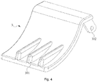
- reinforced ribs 301 are provided on a surface of the ice discharging door 3 facing the interior of the ice storage box 1.
- Each reinforced rib 301 is of a stripe structure, and three reinforced ribs are arranged in parallel.
- the overall strength of the ice discharging door 3 is enhanced.
- the reinforced ribs 301 may be arranged in other forms, and there may be 1, 2, 3, 4 or more reinforced ribs.
- the reinforced ribs 301 may be preferably arranged in a direction perpendicular to the axial direction of the rotating shaft 6.
- the distance between adjacent reinforced ribs 301 should not be too large, so as to preventing large ice cubes or entire ice cubes from escaping therefrom.
- the fixed ice crushing blade 4 is located at the outlet of the ice storage box 1, and one end of the fixed ice crushing blade 4 is fixedly connected to the ice storage box 1 and the other end thereof is hollowly sleeved on the rotating shaft 6 so that the fixed ice crushing blade 4 is fixed inside the ice storage box 1 at a specified position.
- the fixed ice crushing blade 4 has a first ice crushing face and a first backside 402 which are arranged away from and oppositely to each other, with the first ice crushing face being away from the outlet of the ice storage box 1 and having first ice crushing teeth 401, and the first backside 402 facing the outlet of the ice crushing box 1.
- the moving ice crushing blade 5 is sleeved on the rotating shaft 6, and rotates synchronously to the rotating shaft 6.
- the moving ice crushing blade 5 has a second ice crushing face and a second backside 502 which are arranged away from and oppositely to each other; and the moving ice crushing blade 5 moves toward the direction of the fixed ice crushing blade 4, and during the ice crushing, the second ice crushing face faces the first ice crushing face; and the second ice crushing face has second ice crushing teeth 501, and the second backside 502 is planar. Since the second backside 502 of the moving ice crushing blade 5 is a planar structure, advantages of simple structure and easy machining are provided.
- the fixed ice crushing blade 4 and the moving ice crushing blade 5 may be arranged in pair, and the ice crushing teeth of the two ice crushing blades which are arranged in pair may be arranged facing one another.
- the ice crushing teeth are of a wavy or dentate structure, which is advantageous for ice crushing.
- the fixed ice crushing blade 4 and the moving ice crushing blade 5 may be not arranged in pair, and in this case, the fixed ice crushing blade 4 and the moving ice crushing blade 5 may be alternately arranged, and the ice crushing teeth of the fixed ice crushing blade 4 and the moving ice crushing blade 5 are arranged facing one another.
- the driving device for example, a motor
- the rotating shaft 6 drives the stirrer 2 and the moving ice crushing blade 5 to synchronously rotate clockwise.
- the second stirring portion 203 stirs ice cubes
- a pushing force is applied by ice cubes onto the ice discharging door 3 so that the ice discharging door 3 is opened to take more ice cubes.
- the driving device for example, a motor
- the rotating shaft 6 drives the rotating shaft 6 to rotate counterclockwise, and the rotating shaft 6 further drives the moving ice crushing blade 5 to synchronously rotate counterclockwise. That is, the second ice crushing teeth 501 rotate toward the direction of the first ice crushing teeth 401 to gradually narrow the gap therebetween.
- the crushed ice is discharged from the outlet of the ice storage box 1.
- the rotating shaft 6 drives the stirrer 2 to synchronously rotate counterclockwise
- the second stirring portion 203 applies no pushing force onto the ice discharging door 3 by ice cubes
- the second stirring portion 203 can stir and push some large ice cubes or entire ice cubes to move toward the fixed ice crushing blade 4 to ensure that the ice discharging door 3 is closed and no large ice cubes are discharged therefrom. That is, only the crushed ice is discharged.
- different requirements of consumers are satisfied.
- Another embodiment of the present invention provides a refrigerator including an ice maker.
- the ice maker is equipped with the ice storage device as described in any one of the above embodiments.
- An inlet of this ice storage device is communicated with an outlet of the ice maker.
- the refrigerator provided by this embodiment of the present invention since equipped with the ice storage device as described in the above embodiments, has all advantages of the ice storage device, and will not be repeated herein.
Landscapes
- Engineering & Computer Science (AREA)
- Physics & Mathematics (AREA)
- Mechanical Engineering (AREA)
- Thermal Sciences (AREA)
- General Engineering & Computer Science (AREA)
- Devices That Are Associated With Refrigeration Equipment (AREA)
- Mixers Of The Rotary Stirring Type (AREA)
Claims (13)
- Eisspeichervorrichtung, die einen Eisspeicherbehälter (1) umfasst, wobei- eine Eisabgabetür (3) an einem Auslass des Eisspeicherbehälters (1) bereitgestellt ist,- eine Eiszerkleinerungsvorrichtung im Inneren des Eisspeicherbehälters (1) bereitgestellt ist, wobei die Eiszerkleinerungsvorrichtung mindestens ein unbewegliches Eiszerkleinerungsmesser (4) und mindestens ein bewegliches Eiszerkleinerungsmesser (5), das auf einer Drehwelle (6) gelagert ist und sich synchron mit der Drehwelle (6) dreht, umfasst, und die Drehwelle (6) mit einer Antriebsvorrichtung verbunden ist;- mindestens ein Rührer (2) auf der Drehwelle (6) gelagert ist und sich synchron mit der Drehwelle (6) dreht,- der Rührer (2) einen säulenförmigen Rührkörper (201) umfasst, der mindestens einen Rührfinger an seiner säulenförmigen Außenoberfläche aufweist,- der Rührfinger schräg oder senkrecht zu einer axialen Richtung der Drehwelle (6) angeordnet ist, und- ein Spalt zwischen einer Spitze des Rührfingers und der Eisabgabetür aufrechterhalten wird, dadurch gekennzeichnet, dass, wenn die Antriebsvorrichtung die Drehwelle (6) so antreibt, dass sie sich in einer ersten Richtung dreht, der Rührfinger eingerichtet ist, Eiswürfel vorzuschieben, um eine Druckkraft auf die Eisabgabetür (3) auszuüben.
- Eisspeichervorrichtung nach Anspruch 1, dadurch gekennzeichnet, dass mindestens zwei des mindestens einen Rührfingers gleichmäßig entlang des Umfangs des Rührkörpers (201) angeordnet sind.
- Eisspeichervorrichtung nach Anspruch 1 oder Anspruch 2, dadurch gekennzeichnet, dass der Rührfinger einen ersten Rührabschnitt (202) und einen zweiten Rührabschnitt (203) umfasst, wobei ein Ende des ersten Rührabschnitts (202) fest mit der Außenoberfläche des Rührkörpers (201) verbunden ist und das andere Ende davon mit dem zweiten Rührabschnitt (203) verbunden ist, und wobei der zweite Rührabschnitt (203) schräg oder senkrecht zu dem ersten Rührabschnitt (202) angeordnet ist.
- Eisspeichervorrichtung nach einem der Ansprüche 1-3, dadurch gekennzeichnet, dass eine Eisabgabetür (3) vorhanden ist.
- Eisspeichervorrichtung nach einem der Ansprüche 1-4, dadurch gekennzeichnet, dass ein elastisches Element zwischen der Eisabgabetür (3) und dem Eisspeicherbehälter (1) bereitgestellt ist.
- Eisspeichervorrichtung nach einem der Ansprüche 1-5, dadurch gekennzeichnet, dass die Eisabgabetür (3) an dem Eisspeicherbehälter (1) angelenkt ist.
- Eisspeichervorrichtung nach einem der Ansprüche 1-6, dadurch gekennzeichnet, dass mindestens eine verstärkte Rippe (301) an einer Oberfläche der Eisabgabetür (3) angeordnet ist, die einem Innenraum des Eisspeicherbehälters (1) zugewandt ist.
- Eisspeichervorrichtung nach einem der Ansprüche 1-7, dadurch gekennzeichnet, dass sich das unbewegliche Eiszerkleinerungsmesser (4) an dem Auslass des Eisspeicherbehälters (1) befindet, wobei ein Ende des unbeweglichen Eiszerkleinerungsmessers (4) fest mit dem Eisspeicherbehälter (1) verbunden ist und das andere Ende davon hohl auf der Drehwelle (6) gelagert ist; und wobei das unbewegliche Eiszerkleinerungsmesser (4) eine erste Eiszerkleinerungsfläche und eine erste Rückseite (402) aufweist, die entfernt voneinander und entgegengesetzt zueinander angeordnet sind, wobei die erste Eiszerkleinerungsfläche entfernt von dem Auslass des Eisspeicherbehälters (1) ist und erste Eiszerkleinerungszähne (401) aufweist, und wobei die erste Rückseite (402) dem Auslass des Eiszerkleinerungsbehälters (1) zugewandt ist.
- Eisspeichervorrichtung nach Anspruch 8, dadurch gekennzeichnet, dass das bewegliche Eiszerkleinerungsmesser (5) eine zweite Eiszerkleinerungsfläche und eine zweite Rückseite (502) aufweist, die voneinander entfernt und entgegengesetzt zueinander angeordnet sind; und wobei sich das bewegliche Eiszerkleinerungsmesser (5) auf das unbewegliche Eiszerkleinerungsmessers (4) zubewegt, und die zweite Eiszerkleinerungsfläche, während der Eiszerkleinerung, der ersten Eiszerkleinerungsfläche zugewandt ist; und wobei die zweite Eiszerkleinerungsfläche zweite Eiszerkleinerungszähne (501) aufweist und die zweite Rückseite (502) ebenflächig ist.
- Eisspeichervorrichtung nach Anspruch 1, dadurch gekennzeichnet, dass der Rührfinger eingerichtet ist, wenn die Antriebsvorrichtung die Drehwelle (6) so antreibt, dass sie sich in einer zweiten Richtung entgegengesetzt zu der ersten Richtung dreht, Eiswürfel vorzuschieben, um sie auf das unbewegliche Eiszerkleinerungsmesser (4) zuzubewegen.
- Eisspeichervorrichtung nach Anspruch 1, dadurch gekennzeichnet, dass der mindestens eine Rührer (2) zwei oder mehr Rührer (2) umfasst, und
wenn zwei Rührer (2) montiert sind, die zwei Rührer (2) an beiden Enden der Drehwelle (6) im Inneren des Eisspeicherbehälters (1) platziert sind und alle Eiszerkleinerungsmesser zwischen den zwei Rührern (2) montiert sind; und
wenn drei oder mehr Rührer (2) montiert sind, die Rührer (2) und die Eiszerkleinerungsmesser abwechselnd angeordnet sind. - Eiserzeuger, dadurch gekennzeichnet, dass er eine Eisspeichervorrichtung nach einem der Ansprüche 1-11 aufweist, wobei ein Einlass der Eisspeichervorrichtung in Verbindung mit einem Auslass des Eiserzeugers steht.
- Kühlschrank, der einen Eiserzeuger umfasst, dadurch gekennzeichnet, dass er eine Eisspeichervorrichtung nach einem der Ansprüche 1-11 aufweist, wobei ein Einlass der Eisspeichervorrichtung in Verbindung mit einem Auslass des Eiserzeugers steht.
Applications Claiming Priority (2)
| Application Number | Priority Date | Filing Date | Title |
|---|---|---|---|
| CN201510056903.6A CN105987553A (zh) | 2015-02-03 | 2015-02-03 | 储冰装置及冰箱 |
| PCT/CN2015/075515 WO2016123848A1 (zh) | 2015-02-03 | 2015-03-31 | 储冰装置及冰箱 |
Publications (3)
| Publication Number | Publication Date |
|---|---|
| EP3147597A1 EP3147597A1 (de) | 2017-03-29 |
| EP3147597A4 EP3147597A4 (de) | 2017-12-06 |
| EP3147597B1 true EP3147597B1 (de) | 2021-07-07 |
Family
ID=56563358
Family Applications (1)
| Application Number | Title | Priority Date | Filing Date |
|---|---|---|---|
| EP15880803.0A Active EP3147597B1 (de) | 2015-02-03 | 2015-03-31 | Eisaufbewahrungsvorrichtung und kühlschrank |
Country Status (4)
| Country | Link |
|---|---|
| US (2) | US10132545B2 (de) |
| EP (1) | EP3147597B1 (de) |
| CN (1) | CN105987553A (de) |
| WO (1) | WO2016123848A1 (de) |
Families Citing this family (24)
| Publication number | Priority date | Publication date | Assignee | Title |
|---|---|---|---|---|
| KR101798547B1 (ko) * | 2016-04-12 | 2017-11-17 | 동부대우전자 주식회사 | 얼음 분리 성능이 개선된 아이스 빈 및 그 아이스 빈이 구비된 냉장고 |
| CN108413667B (zh) * | 2018-03-01 | 2020-12-04 | 海尔智家股份有限公司 | 一种冰箱用碎冰结构及具有其的冰箱 |
| CN108278851B (zh) * | 2018-03-01 | 2020-12-01 | 海尔智家股份有限公司 | 一种冰箱用碎冰结构及具有其的冰箱 |
| CN108759216B (zh) | 2018-05-21 | 2020-11-20 | 海尔智家股份有限公司 | 碎冰装置及冰箱 |
| CN108800694B (zh) | 2018-05-21 | 2021-03-23 | 海尔智家股份有限公司 | 碎冰装置及冰箱 |
| CN108662821B (zh) | 2018-05-21 | 2020-11-20 | 海尔智家股份有限公司 | 碎冰装置及冰箱 |
| CN108759218B (zh) | 2018-05-21 | 2020-11-20 | 海尔智家股份有限公司 | 碎冰装置及冰箱 |
| CN108759217B (zh) * | 2018-05-21 | 2021-04-23 | 海尔智家股份有限公司 | 碎冰装置及冰箱 |
| CN109028688B (zh) * | 2018-06-19 | 2020-02-07 | 合肥华凌股份有限公司 | 储冰盒以及具有其的冰箱 |
| US10641536B2 (en) * | 2018-08-21 | 2020-05-05 | Haier Us Appliance Solutions, Inc. | Refrigerator appliance and ice bin having a gear assembly therein |
| CN109307392B (zh) * | 2018-09-10 | 2020-04-21 | 海信容声(广东)冰箱有限公司 | 一种出冰装置及冰箱 |
| CN115235157B (zh) * | 2019-04-26 | 2023-07-14 | 青岛海尔电冰箱有限公司 | 碎冰机及冰箱 |
| CN110081641B (zh) * | 2019-05-09 | 2024-06-14 | 广东奥马冰箱有限公司 | 一种自动制冰机储冰盒结构 |
| CN110410907A (zh) * | 2019-07-31 | 2019-11-05 | 广东电网有限责任公司 | 一种节能型冰蓄冷空调系统及碎冰装置 |
| USD994835S1 (en) * | 2020-03-20 | 2023-08-08 | Microfilter Co., Ltd | Filter case for water purification |
| CN114076430B (zh) * | 2020-08-13 | 2023-02-17 | 青岛海尔电冰箱有限公司 | 碎冰装置 |
| CN114076429B (zh) * | 2020-08-13 | 2023-11-07 | 青岛海尔电冰箱有限公司 | 碎冰装置 |
| CN114076428B (zh) * | 2020-08-13 | 2023-04-18 | 青岛海尔电冰箱有限公司 | 碎冰装置 |
| USD1033591S1 (en) * | 2021-07-14 | 2024-07-02 | Emd Millipore Corporation | Filter assembly stand |
| USD1024269S1 (en) * | 2021-07-14 | 2024-04-23 | Emd Millipore Corporation | Filter assembly holder |
| USD1025288S1 (en) * | 2021-07-14 | 2024-04-30 | Emd Millipore Corporation | Filter assembly bracket |
| WO2023070539A1 (zh) * | 2021-10-29 | 2023-05-04 | 合肥美的电冰箱有限公司 | 储冰盒、制冰机及制冷设备 |
| CN117663649A (zh) * | 2023-11-03 | 2024-03-08 | 海信冰箱有限公司 | 冰箱 |
| WO2025092243A1 (zh) * | 2023-11-03 | 2025-05-08 | 海信冰箱有限公司 | 冰箱 |
Family Cites Families (16)
| Publication number | Priority date | Publication date | Assignee | Title |
|---|---|---|---|---|
| EP1491833A1 (de) * | 2003-06-25 | 2004-12-29 | Lg Electronics Inc. | Eisspeicher für einen Eiserzeuger eines Kühlschrankes |
| US7631513B2 (en) * | 2005-03-25 | 2009-12-15 | Lg Electronics Inc. | Ice bank of refrigerator |
| CN200946955Y (zh) * | 2006-06-16 | 2007-09-12 | 顾维 | 具有统一出口自动取整冰、碎冰和冰水机构的制冰机 |
| KR20080036696A (ko) | 2006-10-24 | 2008-04-29 | 엘지전자 주식회사 | 얼음취출장치 및 이를 구비하는 냉장고와 그 제어방법 |
| DE102006061079A1 (de) * | 2006-12-22 | 2008-06-26 | BSH Bosch und Siemens Hausgeräte GmbH | Kältegerät mit Eisspender und Baugruppe dafür |
| KR101334248B1 (ko) * | 2007-05-28 | 2013-11-29 | 엘지전자 주식회사 | 얼음 취출 장치 및 이를 구비한 냉장고 |
| JP5147545B2 (ja) * | 2008-05-30 | 2013-02-20 | 日立アプライアンス株式会社 | 冷蔵庫 |
| JP5826034B2 (ja) | 2009-03-04 | 2015-12-02 | ビーイー・エアロスペース・インコーポレーテッドB/E Aerospace, Inc. | 航空機のギャレーカートコンパートメント用の壁掛け型ポイントオブユース空気冷却器 |
| US20110120152A1 (en) * | 2009-11-23 | 2011-05-26 | Arun Madhav Talegaonkar | Method and apparatus for crushing ice within a refrigerator |
| EP3537076B1 (de) * | 2009-12-22 | 2021-08-11 | LG Electronics Inc. | Kühlschrank |
| CN102278843A (zh) * | 2011-05-27 | 2011-12-14 | 合肥美的荣事达电冰箱有限公司 | 碎冰装置及具有该碎冰装置的冰箱 |
| CN102818411A (zh) * | 2012-08-08 | 2012-12-12 | 海信容声(广东)冰箱有限公司 | 一种冰箱出冰系统及冰箱 |
| KR102189239B1 (ko) * | 2013-05-27 | 2020-12-09 | 삼성전자주식회사 | 냉장고 |
| CN104006595B (zh) * | 2014-05-20 | 2016-06-29 | 海信容声(广东)冰箱有限公司 | 一种冰箱储冰盒组件及带有其的冰箱 |
| CN204227784U (zh) * | 2014-11-10 | 2015-03-25 | 海信容声(广东)冰箱有限公司 | 一种冰箱碎冰装置及冰箱 |
| CN104390402B (zh) * | 2014-11-10 | 2016-08-17 | 海信容声(广东)冰箱有限公司 | 一种冰箱碎冰装置及冰箱 |
-
2015
- 2015-02-03 CN CN201510056903.6A patent/CN105987553A/zh active Pending
- 2015-03-31 WO PCT/CN2015/075515 patent/WO2016123848A1/zh not_active Ceased
- 2015-03-31 EP EP15880803.0A patent/EP3147597B1/de active Active
- 2015-03-31 US US15/032,451 patent/US10132545B2/en active Active
-
2018
- 2018-10-12 US US16/159,362 patent/US10677506B2/en active Active
Non-Patent Citations (1)
| Title |
|---|
| None * |
Also Published As
| Publication number | Publication date |
|---|---|
| EP3147597A1 (de) | 2017-03-29 |
| EP3147597A4 (de) | 2017-12-06 |
| US10132545B2 (en) | 2018-11-20 |
| US20190049166A1 (en) | 2019-02-14 |
| US10677506B2 (en) | 2020-06-09 |
| CN105987553A (zh) | 2016-10-05 |
| US20160341463A1 (en) | 2016-11-24 |
| WO2016123848A1 (zh) | 2016-08-11 |
Similar Documents
| Publication | Publication Date | Title |
|---|---|---|
| EP3147597B1 (de) | Eisaufbewahrungsvorrichtung und kühlschrank | |
| JP5833174B2 (ja) | 食品用ホモジナイザ | |
| US20090320511A1 (en) | Ice dispenser | |
| EP3851771B1 (de) | Eiszerkleinerungsvorrichtung und kühlschrank | |
| EP3232141A1 (de) | Eisbehälter und kühlschrank mit dem eisbehälter | |
| CN104006595A (zh) | 一种冰箱储冰盒组件及带有其的冰箱 | |
| CN106556193A (zh) | 制冰组件及制冰机 | |
| KR101798547B1 (ko) | 얼음 분리 성능이 개선된 아이스 빈 및 그 아이스 빈이 구비된 냉장고 | |
| EP4368922A2 (de) | Eisspeicher für kühlschrank | |
| CN111829239B (zh) | 碎冰装置及冰箱 | |
| US3784341A (en) | Hand tool for dispensing frozen food items | |
| CN111829235A (zh) | 碎冰装置及冰箱 | |
| CN108278849B (zh) | 一种储水装置及具有该储水装置的冰箱 | |
| CN111854253A (zh) | 碎冰机及冰箱 | |
| CN113465245B (zh) | 冰箱门体及冰箱 | |
| CN215983400U (zh) | 推冰盘、制冰装置和冰箱 | |
| JPH10230183A (ja) | 粉砕器 | |
| CN210330372U (zh) | 粉碎刀组件、杯体组件和食物料理机 | |
| CN115727581B (zh) | 出冰机构、制冰装置及冰箱 | |
| JP4198665B2 (ja) | 密閉加圧混練機 | |
| US12259170B2 (en) | Refrigerator | |
| KR101176304B1 (ko) | 분쇄 스크류, 분쇄통 및 이를 구비하는 음식물 처리기의 분쇄로 | |
| JP2008014539A (ja) | アイスディスペンサ | |
| JPH10292965A (ja) | アイスクラッシャ | |
| JP2019100596A (ja) | 砕氷装置及び冷蔵庫 |
Legal Events
| Date | Code | Title | Description |
|---|---|---|---|
| STAA | Information on the status of an ep patent application or granted ep patent |
Free format text: STATUS: THE INTERNATIONAL PUBLICATION HAS BEEN MADE |
|
| PUAI | Public reference made under article 153(3) epc to a published international application that has entered the european phase |
Free format text: ORIGINAL CODE: 0009012 |
|
| STAA | Information on the status of an ep patent application or granted ep patent |
Free format text: STATUS: REQUEST FOR EXAMINATION WAS MADE |
|
| 17P | Request for examination filed |
Effective date: 20161115 |
|
| AK | Designated contracting states |
Kind code of ref document: A1 Designated state(s): AL AT BE BG CH CY CZ DE DK EE ES FI FR GB GR HR HU IE IS IT LI LT LU LV MC MK MT NL NO PL PT RO RS SE SI SK SM TR |
|
| AX | Request for extension of the european patent |
Extension state: BA ME |
|
| REG | Reference to a national code |
Ref country code: DE Ref legal event code: R079 Ref document number: 602015071205 Country of ref document: DE Free format text: PREVIOUS MAIN CLASS: F25C0005180000 Ipc: F25C0005040000 |
|
| A4 | Supplementary search report drawn up and despatched |
Effective date: 20171108 |
|
| RIC1 | Information provided on ipc code assigned before grant |
Ipc: F25C 5/04 20060101AFI20171102BHEP Ipc: F25C 5/18 20060101ALI20171102BHEP |
|
| DAV | Request for validation of the european patent (deleted) | ||
| DAX | Request for extension of the european patent (deleted) | ||
| STAA | Information on the status of an ep patent application or granted ep patent |
Free format text: STATUS: EXAMINATION IS IN PROGRESS |
|
| 17Q | First examination report despatched |
Effective date: 20190521 |
|
| GRAP | Despatch of communication of intention to grant a patent |
Free format text: ORIGINAL CODE: EPIDOSNIGR1 |
|
| STAA | Information on the status of an ep patent application or granted ep patent |
Free format text: STATUS: GRANT OF PATENT IS INTENDED |
|
| INTG | Intention to grant announced |
Effective date: 20210322 |
|
| GRAS | Grant fee paid |
Free format text: ORIGINAL CODE: EPIDOSNIGR3 |
|
| GRAA | (expected) grant |
Free format text: ORIGINAL CODE: 0009210 |
|
| STAA | Information on the status of an ep patent application or granted ep patent |
Free format text: STATUS: THE PATENT HAS BEEN GRANTED |
|
| AK | Designated contracting states |
Kind code of ref document: B1 Designated state(s): AL AT BE BG CH CY CZ DE DK EE ES FI FR GB GR HR HU IE IS IT LI LT LU LV MC MK MT NL NO PL PT RO RS SE SI SK SM TR |
|
| REG | Reference to a national code |
Ref country code: GB Ref legal event code: FG4D |
|
| REG | Reference to a national code |
Ref country code: AT Ref legal event code: REF Ref document number: 1408978 Country of ref document: AT Kind code of ref document: T Effective date: 20210715 |
|
| REG | Reference to a national code |
Ref country code: DE Ref legal event code: R096 Ref document number: 602015071205 Country of ref document: DE |
|
| REG | Reference to a national code |
Ref country code: IE Ref legal event code: FG4D |
|
| REG | Reference to a national code |
Ref country code: LT Ref legal event code: MG9D |
|
| REG | Reference to a national code |
Ref country code: NL Ref legal event code: MP Effective date: 20210707 |
|
| REG | Reference to a national code |
Ref country code: AT Ref legal event code: MK05 Ref document number: 1408978 Country of ref document: AT Kind code of ref document: T Effective date: 20210707 |
|
| PG25 | Lapsed in a contracting state [announced via postgrant information from national office to epo] |
Ref country code: SE Free format text: LAPSE BECAUSE OF FAILURE TO SUBMIT A TRANSLATION OF THE DESCRIPTION OR TO PAY THE FEE WITHIN THE PRESCRIBED TIME-LIMIT Effective date: 20210707 Ref country code: RS Free format text: LAPSE BECAUSE OF FAILURE TO SUBMIT A TRANSLATION OF THE DESCRIPTION OR TO PAY THE FEE WITHIN THE PRESCRIBED TIME-LIMIT Effective date: 20210707 Ref country code: HR Free format text: LAPSE BECAUSE OF FAILURE TO SUBMIT A TRANSLATION OF THE DESCRIPTION OR TO PAY THE FEE WITHIN THE PRESCRIBED TIME-LIMIT Effective date: 20210707 Ref country code: BG Free format text: LAPSE BECAUSE OF FAILURE TO SUBMIT A TRANSLATION OF THE DESCRIPTION OR TO PAY THE FEE WITHIN THE PRESCRIBED TIME-LIMIT Effective date: 20211007 Ref country code: AT Free format text: LAPSE BECAUSE OF FAILURE TO SUBMIT A TRANSLATION OF THE DESCRIPTION OR TO PAY THE FEE WITHIN THE PRESCRIBED TIME-LIMIT Effective date: 20210707 Ref country code: LT Free format text: LAPSE BECAUSE OF FAILURE TO SUBMIT A TRANSLATION OF THE DESCRIPTION OR TO PAY THE FEE WITHIN THE PRESCRIBED TIME-LIMIT Effective date: 20210707 Ref country code: FI Free format text: LAPSE BECAUSE OF FAILURE TO SUBMIT A TRANSLATION OF THE DESCRIPTION OR TO PAY THE FEE WITHIN THE PRESCRIBED TIME-LIMIT Effective date: 20210707 Ref country code: ES Free format text: LAPSE BECAUSE OF FAILURE TO SUBMIT A TRANSLATION OF THE DESCRIPTION OR TO PAY THE FEE WITHIN THE PRESCRIBED TIME-LIMIT Effective date: 20210707 Ref country code: PT Free format text: LAPSE BECAUSE OF FAILURE TO SUBMIT A TRANSLATION OF THE DESCRIPTION OR TO PAY THE FEE WITHIN THE PRESCRIBED TIME-LIMIT Effective date: 20211108 Ref country code: NO Free format text: LAPSE BECAUSE OF FAILURE TO SUBMIT A TRANSLATION OF THE DESCRIPTION OR TO PAY THE FEE WITHIN THE PRESCRIBED TIME-LIMIT Effective date: 20211007 Ref country code: NL Free format text: LAPSE BECAUSE OF FAILURE TO SUBMIT A TRANSLATION OF THE DESCRIPTION OR TO PAY THE FEE WITHIN THE PRESCRIBED TIME-LIMIT Effective date: 20210707 |
|
| PG25 | Lapsed in a contracting state [announced via postgrant information from national office to epo] |
Ref country code: PL Free format text: LAPSE BECAUSE OF FAILURE TO SUBMIT A TRANSLATION OF THE DESCRIPTION OR TO PAY THE FEE WITHIN THE PRESCRIBED TIME-LIMIT Effective date: 20210707 Ref country code: LV Free format text: LAPSE BECAUSE OF FAILURE TO SUBMIT A TRANSLATION OF THE DESCRIPTION OR TO PAY THE FEE WITHIN THE PRESCRIBED TIME-LIMIT Effective date: 20210707 Ref country code: GR Free format text: LAPSE BECAUSE OF FAILURE TO SUBMIT A TRANSLATION OF THE DESCRIPTION OR TO PAY THE FEE WITHIN THE PRESCRIBED TIME-LIMIT Effective date: 20211008 |
|
| REG | Reference to a national code |
Ref country code: DE Ref legal event code: R097 Ref document number: 602015071205 Country of ref document: DE |
|
| PG25 | Lapsed in a contracting state [announced via postgrant information from national office to epo] |
Ref country code: DK Free format text: LAPSE BECAUSE OF FAILURE TO SUBMIT A TRANSLATION OF THE DESCRIPTION OR TO PAY THE FEE WITHIN THE PRESCRIBED TIME-LIMIT Effective date: 20210707 |
|
| PLBE | No opposition filed within time limit |
Free format text: ORIGINAL CODE: 0009261 |
|
| STAA | Information on the status of an ep patent application or granted ep patent |
Free format text: STATUS: NO OPPOSITION FILED WITHIN TIME LIMIT |
|
| PG25 | Lapsed in a contracting state [announced via postgrant information from national office to epo] |
Ref country code: SM Free format text: LAPSE BECAUSE OF FAILURE TO SUBMIT A TRANSLATION OF THE DESCRIPTION OR TO PAY THE FEE WITHIN THE PRESCRIBED TIME-LIMIT Effective date: 20210707 Ref country code: SK Free format text: LAPSE BECAUSE OF FAILURE TO SUBMIT A TRANSLATION OF THE DESCRIPTION OR TO PAY THE FEE WITHIN THE PRESCRIBED TIME-LIMIT Effective date: 20210707 Ref country code: RO Free format text: LAPSE BECAUSE OF FAILURE TO SUBMIT A TRANSLATION OF THE DESCRIPTION OR TO PAY THE FEE WITHIN THE PRESCRIBED TIME-LIMIT Effective date: 20210707 Ref country code: EE Free format text: LAPSE BECAUSE OF FAILURE TO SUBMIT A TRANSLATION OF THE DESCRIPTION OR TO PAY THE FEE WITHIN THE PRESCRIBED TIME-LIMIT Effective date: 20210707 Ref country code: CZ Free format text: LAPSE BECAUSE OF FAILURE TO SUBMIT A TRANSLATION OF THE DESCRIPTION OR TO PAY THE FEE WITHIN THE PRESCRIBED TIME-LIMIT Effective date: 20210707 Ref country code: AL Free format text: LAPSE BECAUSE OF FAILURE TO SUBMIT A TRANSLATION OF THE DESCRIPTION OR TO PAY THE FEE WITHIN THE PRESCRIBED TIME-LIMIT Effective date: 20210707 |
|
| 26N | No opposition filed |
Effective date: 20220408 |
|
| PG25 | Lapsed in a contracting state [announced via postgrant information from national office to epo] |
Ref country code: IT Free format text: LAPSE BECAUSE OF FAILURE TO SUBMIT A TRANSLATION OF THE DESCRIPTION OR TO PAY THE FEE WITHIN THE PRESCRIBED TIME-LIMIT Effective date: 20210707 |
|
| PG25 | Lapsed in a contracting state [announced via postgrant information from national office to epo] |
Ref country code: MC Free format text: LAPSE BECAUSE OF FAILURE TO SUBMIT A TRANSLATION OF THE DESCRIPTION OR TO PAY THE FEE WITHIN THE PRESCRIBED TIME-LIMIT Effective date: 20210707 |
|
| REG | Reference to a national code |
Ref country code: CH Ref legal event code: PL |
|
| REG | Reference to a national code |
Ref country code: BE Ref legal event code: MM Effective date: 20220331 |
|
| PG25 | Lapsed in a contracting state [announced via postgrant information from national office to epo] |
Ref country code: LU Free format text: LAPSE BECAUSE OF NON-PAYMENT OF DUE FEES Effective date: 20220331 Ref country code: LI Free format text: LAPSE BECAUSE OF NON-PAYMENT OF DUE FEES Effective date: 20220331 Ref country code: IE Free format text: LAPSE BECAUSE OF NON-PAYMENT OF DUE FEES Effective date: 20220331 Ref country code: CH Free format text: LAPSE BECAUSE OF NON-PAYMENT OF DUE FEES Effective date: 20220331 |
|
| PG25 | Lapsed in a contracting state [announced via postgrant information from national office to epo] |
Ref country code: BE Free format text: LAPSE BECAUSE OF NON-PAYMENT OF DUE FEES Effective date: 20220331 |
|
| P01 | Opt-out of the competence of the unified patent court (upc) registered |
Effective date: 20230511 |
|
| PG25 | Lapsed in a contracting state [announced via postgrant information from national office to epo] |
Ref country code: HU Free format text: LAPSE BECAUSE OF FAILURE TO SUBMIT A TRANSLATION OF THE DESCRIPTION OR TO PAY THE FEE WITHIN THE PRESCRIBED TIME-LIMIT; INVALID AB INITIO Effective date: 20150331 |
|
| PG25 | Lapsed in a contracting state [announced via postgrant information from national office to epo] |
Ref country code: MK Free format text: LAPSE BECAUSE OF FAILURE TO SUBMIT A TRANSLATION OF THE DESCRIPTION OR TO PAY THE FEE WITHIN THE PRESCRIBED TIME-LIMIT Effective date: 20210707 Ref country code: CY Free format text: LAPSE BECAUSE OF FAILURE TO SUBMIT A TRANSLATION OF THE DESCRIPTION OR TO PAY THE FEE WITHIN THE PRESCRIBED TIME-LIMIT Effective date: 20210707 |
|
| PG25 | Lapsed in a contracting state [announced via postgrant information from national office to epo] |
Ref country code: TR Free format text: LAPSE BECAUSE OF FAILURE TO SUBMIT A TRANSLATION OF THE DESCRIPTION OR TO PAY THE FEE WITHIN THE PRESCRIBED TIME-LIMIT Effective date: 20210707 |
|
| PG25 | Lapsed in a contracting state [announced via postgrant information from national office to epo] |
Ref country code: MT Free format text: LAPSE BECAUSE OF FAILURE TO SUBMIT A TRANSLATION OF THE DESCRIPTION OR TO PAY THE FEE WITHIN THE PRESCRIBED TIME-LIMIT Effective date: 20210707 |
|
| PGFP | Annual fee paid to national office [announced via postgrant information from national office to epo] |
Ref country code: GB Payment date: 20260324 Year of fee payment: 12 |
|
| PGFP | Annual fee paid to national office [announced via postgrant information from national office to epo] |
Ref country code: DE Payment date: 20260319 Year of fee payment: 12 |
|
| PGFP | Annual fee paid to national office [announced via postgrant information from national office to epo] |
Ref country code: FR Payment date: 20260320 Year of fee payment: 12 |