EP3147635B1 - Fixation de sonde et ecarteur - Google Patents
Fixation de sonde et ecarteur Download PDFInfo
- Publication number
- EP3147635B1 EP3147635B1 EP16188105.7A EP16188105A EP3147635B1 EP 3147635 B1 EP3147635 B1 EP 3147635B1 EP 16188105 A EP16188105 A EP 16188105A EP 3147635 B1 EP3147635 B1 EP 3147635B1
- Authority
- EP
- European Patent Office
- Prior art keywords
- spacer
- signal conductor
- holder
- seal
- probe
- Prior art date
- Legal status (The legal status is an assumption and is not a legal conclusion. Google has not performed a legal analysis and makes no representation as to the accuracy of the status listed.)
- Active
Links
Images
Classifications
-
- G—PHYSICS
- G01—MEASURING; TESTING
- G01F—MEASURING VOLUME, VOLUME FLOW, MASS FLOW OR LIQUID LEVEL; METERING BY VOLUME
- G01F23/00—Indicating or measuring liquid level or level of fluent solid material, e.g. indicating in terms of volume or indicating by means of an alarm
- G01F23/22—Indicating or measuring liquid level or level of fluent solid material, e.g. indicating in terms of volume or indicating by means of an alarm by measuring physical variables, other than linear dimensions, pressure or weight, dependent on the level to be measured, e.g. by difference of heat transfer of steam or water
- G01F23/28—Indicating or measuring liquid level or level of fluent solid material, e.g. indicating in terms of volume or indicating by means of an alarm by measuring physical variables, other than linear dimensions, pressure or weight, dependent on the level to be measured, e.g. by difference of heat transfer of steam or water by measuring the variations of parameters of electromagnetic or acoustic waves applied directly to the liquid or fluent solid material
- G01F23/284—Electromagnetic waves
-
- G—PHYSICS
- G01—MEASURING; TESTING
- G01D—MEASURING NOT SPECIALLY ADAPTED FOR A SPECIFIC VARIABLE; ARRANGEMENTS FOR MEASURING TWO OR MORE VARIABLES NOT COVERED IN A SINGLE OTHER SUBCLASS; TARIFF METERING APPARATUS; MEASURING OR TESTING NOT OTHERWISE PROVIDED FOR
- G01D11/00—Component parts of measuring arrangements not specially adapted for a specific variable
- G01D11/30—Supports specially adapted for an instrument; Supports specially adapted for a set of instruments
-
- G—PHYSICS
- G01—MEASURING; TESTING
- G01S—RADIO DIRECTION-FINDING; RADIO NAVIGATION; DETERMINING DISTANCE OR VELOCITY BY USE OF RADIO WAVES; LOCATING OR PRESENCE-DETECTING BY USE OF THE REFLECTION OR RERADIATION OF RADIO WAVES; ANALOGOUS ARRANGEMENTS USING OTHER WAVES
- G01S7/00—Details of systems according to groups G01S13/00, G01S15/00, G01S17/00
- G01S7/02—Details of systems according to groups G01S13/00, G01S15/00, G01S17/00 of systems according to group G01S13/00
- G01S7/027—Constructional details of housings, e.g. form, type, material or ruggedness
Definitions
- the invention relates to a probe holder for a level measuring device working according to the radar principle, with a holder housing, with a signal conductor for conducting transmission and / or reception signals and with a spacer, the signal conductor from the interior of the holder housing through a process-side opening of the holder housing is guided into the process-side outer space of the holder housing, the spacer being arranged in the opening of the holder housing and holding the signal conductor at a distance from the holder housing in the opening, the spacer being shrunk into the holder housing in such a way that a tight seal between the holder housing when shrunk and the spacer is made.
- Level measuring devices which work according to the radar principle, are used to measure levels in containers such as tanks or silos.
- So-called guided radar systems based on the principle of time domain reflectometry (TDR) are frequently used; The probe holders mentioned at the outset are of interest for such devices.
- TDR time domain reflectometry
- electromagnetic signals are generated here by electronics, coupled into a probe and guided along the probe in the direction of the medium whose level is to be determined.
- the extent of the probe defines the measuring range of the level measuring device. In operation, the probe extends at least partially into the medium.
- the end of the probe that comes into contact with the medium is usually designed as a free end, but it can also be fixed to the bottom of the container.
- the signals carried by the probe are at least partially reflected by the surface of the medium when entering the medium due to the jump in the refractive index or the permittivity at the medium interface and run back to the electronics at the probe.
- the fill level of the medium is determined from the transit time between the transmission of the electromagnetic signals and the reception of the reflected signals. Very short radio pulses are mostly used as signals.
- the principle of time domain reflectometry is particularly advantageous because the properties of the medium, for example the density, the conductivity and the dielectric constant, have little or no influence on the measurement.
- the ambient conditions such as pressure and temperature in the process room also do not influence the measurement results; Changing environmental conditions, such as rising or falling ambient pressure or rising or falling ambient temperature, do not affect the measuring accuracy of a TDR level measuring device.
- the measurement using the TDR principle is also suitable for determining interface layers and thus for specifying on the one hand the total fill level of the medium and on the other hand specifying the interface height.
- rod probes or coaxial probes have proven to be advantageous for measuring the fill level of liquids
- rope probes have become established for the fill level measurement of bulk materials.
- the level measuring devices can be exposed to extreme influences.
- the extreme influences include, for example, very high temperatures or high pressures.
- the interface between the level measuring device and the process space that is to say for example the container filled with the medium, to be sealed. It may also be necessary for this interface to be designed to be pressure-resistant and / or diffusion-tight for reasons of explosion protection.
- the probes as a guiding element for the electromagnetic radiation connect the process space with its sometimes very rough physical boundary conditions to areas in the housing of the measuring device, which house sensitive electronic components, for example, which are used to generate and couple in the radar signals and which are also used for reception and evaluation of the electromagnetic reflection signals are set up. So there is always the question of an effective one physical delimitation of the different areas which are traversed by the probe, the probe holder, which is in direct contact with the probe, being of particular importance. On the one hand, probe holders have the task of holding the probe securely, in particular in such a way that the electromagnetic radiation passed through the probe can pass through as undisturbed as possible, in particular without disturbing reflections; process space.
- a probe holder with a holder housing is known.
- a signal conductor is passed through an opening on the process side of the housing.
- a probe holder with a holder housing in which a signal conductor is passed through an opening in the process side of the housing.
- a spacer is arranged in the opening and keeps the signal conductor spaced from the housing. In order to achieve a sealing seal between the holder housing and the spacer, the spacer is shrunk into the holder housing.
- a microwave level measuring device with a filled waveguide is known.
- the waveguide filling and the waveguide jacket are pressed together.
- a ring is arranged at the pressing point of the waveguide filling and waveguide jacket, which is made of a material with low thermal expansion.
- the ring serves to fix the pressing point in the event of an increase in temperature, since it does not expand or only expands slightly due to its material.
- the object of the invention is to provide a probe holder which realizes a seal against the process space in a simple but effective manner.
- the above-mentioned and derived object is achieved in that at least one seal is arranged between the holder housing and the spacer, the seal being arranged as an additional separate seal between opposing surfaces of the holder housing and spacer, which are not subjected to force by the shrinking and are pressed against one another ,
- the spacer is shrunk into the holder housing in such a way that a tight seal is produced between the holder housing and the spacer when it is shrunk.
- a tight seal between the holder housing and the spacer is achieved in a very simple manner without the use of sealing elements.
- This has the advantage that - since separate sealing elements can be dispensed with entirely - no wear and tear and no wear and tear of sealing elements can take place, as a result of which a sealing effect could be impaired.
- this seal is maintenance-free and there is no need for additional assembly work.
- spacers and bracket housings do not have to be prepared for receiving separate seals, such as by inserting grooves.
- a tight seal is one that is dust-tight and / or liquid-tight and / or gas-tight.
- At least one seal is arranged between the holder housing and the spacer.
- the seal is arranged between opposing surfaces of the holder housing and the spacer, which is not acted upon by the shrinking and are pressed together.
- This has the advantage that the seal is not thermally stressed when shrinking, since it does not necessarily have to come into contact with a heated surface.
- This is preferably also implemented so that the seal does not hinder the actual shrinking, in particular the seal produced by the shrinking.
- the seal is therefore not in the area of the sealing contact produced by the shrink-fitting between the holder housing and the spacer.
- the seal is attached to the end of the spacer on the inside of the housing, ie on a surface of the spacer which faces into the interior of the holder housing.
- this additional, separate seal is particularly advantageous if the shrinkage is loosened or completely eliminated in the event of a particular thermal load on the level measuring device. If unforeseen changes in the state of the process occur, for example a sharp increase in temperature, and the maximum temperature is above a critical temperature such that the bracket housing expands, this can result in the spacer no longer being ideally shrunk into the bracket housing and thus the one before achieved tightness is canceled.
- the additional seal is provided in order to prevent the medium from penetrating into the level measuring device or the process space conditions acting on the level measuring device, in particular the electronics of the level measuring device.
- the seal is preferably designed as a graphite seal, in particular as a graphite sealing ring.
- a seal which is designed as a gold seal, in particular as a gold sealing ring, is also advantageous.
- a plurality of seals are implemented, in particular two seals, one seal being designed as a graphite sealing ring and another seal as a gold sealing ring.
- a further preferred embodiment of the probe holder according to the invention is characterized in that the holder housing has at least one web on the process space side, that the web at least partially surrounds the opening for receiving the spacer and that the web is shaped such that it surrounds the spacer on the process side.
- This configuration is particularly advantageous also in the case in which the mounting housing is heated by changing environmental conditions, in particular process room conditions, in such a way that it expands so far that the spacer is no longer in the shrunk state.
- the spacer is no longer held by the holder housing and slides out of the process-side opening of the holder housing.
- the web that surrounds the opening prevents the spacer from slipping because it is held by the web.
- a seal is attached to the inside of the housing or to a surface of the spacer facing the interior of the holder housing, the interplay between the web and the seal maintains a tight seal between the spacer and the holder housing.
- the web can be realized in different ways.
- the web is designed such that it completely surrounds the opening for receiving the spacer and completely surrounds the spacer.
- An embodiment is also conceivable such that a plurality of webs is provided, each web only partially delimiting the opening.
- two opposing webs can be provided.
- the webs are preferably arranged distributed uniformly over the circumference of the opening.
- the web or webs are shaped so that they enclose the spacer or that they enclose the spacer. This can be realized, for example, in that the web (s) is / are bent in the direction of the spacer after the spacer has been shrunk on.
- a tight seal between the spacer and the bracket housing has been treated.
- the signal conductor is guided from the interior of the holder housing through the process-side opening of the holder housing into the process-side outer space of the holder housing, the spacer being arranged in the opening of the holder housing.
- a particularly preferred embodiment of the probe holder according to the invention is characterized in that in the shrunk-on state, the spacer is compressed in such a way that the signal conductor is squeezed in the spacer, so that a tight seal is produced between the signal conductor and the spacer.
- the spacer is shrunk onto the signal conductor. Whether this is reasonably possible, ie whether the temperature-dependent material expansion or contraction is sufficiently large, depends on the material of the spacer. Nevertheless, small shrinking effects can also be used to support the resulting tight pressing of the spacer onto the signal conductor.
- the combination of both measures can have the effect that the force acting radially on the circumference of the spacer due to the shrinking of the spacer in the holder housing and the contraction of the spacer caused by thermal treatment of the spacer jointly lead to a tight seal between the spacer and the signal conductor.
- the probe holder has a signal conductor, it does not have to be the actual probe. Rather, the signal conductor can be a connecting element between the electronics generating the signals and the probe leading the signals into the process space. Then the signals from the signal conductor must be coupled into the probe.
- a preferred embodiment of the probe holder according to the invention is characterized in that an adapter is connected on the process room side to the signal conductor and is used to connect a probe.
- the connection between the signal conductor and the adapter can be realized in different ways.
- the connection between the signal conductor and the adapter is realized in that the signal conductor has a thread, that the adapter has a corresponding mating thread and that the adapter is screwed to the signal conductor. So the connection can be made very easily and again be solved.
- the probe is connected to the adapter. This can be realized, for example, in that the adapter and the probe are configured in one piece, namely by designing the end of the probe facing the probe holder as an adapter.
- a further embodiment of the probe holder according to the invention is characterized in that the adapter and the signal conductor are connected to one another in such a way that the adapter and the spacer form at least one indirect contact surface and that a seal is arranged between the adapter and the spacer. If the signal conductor and the adapter are screwed together, then a screw-in effect is achieved.
- a preferred embodiment of the probe holder according to the invention is characterized in that the holder housing and the signal conductor consist of a metal.
- the holder housing and the signal conductor can be made of the same metallic material.
- the bracket housing can also consist of a first metal and the signal conductor made of a second metal.
- a further embodiment is characterized in that the spacer consists of an insulator.
- the signal conductor is preferably made of a metal with a low thermal expansion coefficient and a high mechanical strength. Molybdenum is particularly suitable for this.
- a metal with a high thermal expansion coefficient, in particular a higher expansion coefficient than that of the metal used for the signal conductor, is preferably used for the mounting housing.
- the use of nickel alloys, titanium or stainless steel is recommended.
- a ceramic, such as aluminum oxide, or a plastic, such as PEEK or PTFE, is suitable for the spacer.
- the probe holder itself can be attached to the wall surrounding the process space, for example, via a flange.
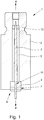
- Probe holder 1 for a level measuring device operating according to the radar principle. This embodiment does not fall under the subject matter of claim 1 since it does not implement the additional seal according to the invention, but it shows features of the invention according to the dependent claims.
- Probe holder 1 comprises a holder housing 2 and a signal conductor 3. The signal conductor 3 is led from the interior 5 of the holder housing 2 through a process-side opening 6 of the holder housing 2 into the process-side exterior.
- the process-side exterior is not shown in the form of a closed process room, but is illustrated by the arrow labeled P.
- the signal conductor 3 is used to conduct transmission and / or reception signals, a transmission signal being generated by electronics (not shown) and being coupled into the signal conductor 3 on the electronics side - illustrated by the arrow labeled E -.
- a received signal is coupled into the signal conductor 3 on the process room side and passed to electronics that implement an evaluation unit.
- the signal conductor 3 consists of a metal.
- the bracket housing 2 is also made of a metal. So that the signal conductor 3 does not come into contact with the holder housing 2, a spacer 4 is arranged in the opening 6, which holds the signal conductor 3 at a distance from the holder housing 2.
- the spacer 4 consists of an insulator.
- the signal conductor 3 is held at a distance from the holder housing 2 by a second insulator 13.
- the signal conductor 3 is tapered.
- the tapered ends of the signal conductor 3 are guided through recesses through the spacer 4 and the insulator 13, so that the spacer 4 and also the insulator 13 encompass the signal conductor 3 and the signal conductor 3 is mounted in the holder housing 2.
- the housing interior housing the electronics In order to protect the electronics from the medium to be measured, or to protect the electronics from the process room conditions, the housing interior housing the electronics must be sealed off from the process room P. This is realized in that the spacer 4 is shrunk into the holder housing 2 in such a way that a tight seal 7 is produced between the holder housing 2 and the spacer 4 in the shrunk state.
- a maintenance-free seal is thus implemented in a very simple manner - maintenance-free because no wear-sensitive aids such as sealing rings or the like are used that have a limited service life.
- the probe holder 1 shown is further characterized in that, in the shrunk-in state, the spacer 4 is compressed in such a way that the signal conductor 3 is squeezed into the spacer 4, so that a tight seal 10 is produced between the signal conductor 3 and the spacer 4. In this way, the probe holder 1 is completely sealed off from the process space P.
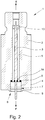
- FIG. 2 Another embodiment of a probe holder 1 is shown.
- the same reference numerals designate the same elements.
- probe holder 1 differs from that in Fig. 1 shown probe holder 1 in that the signal conductor 3 is not squeezed into the holder housing 2 in the shrunk state of the spacer 4.
- a seal 14 is arranged between the signal conductor 3 and the spacer 4.
- the holder housing 2 has a web 9 on the process side. The web 9 completely surrounds the opening 6 for receiving the spacer 4 and is shaped such that it surrounds the spacer 4 on the process side.
- the web 9 has the opening 6 for receiving the spacer 4 not completely, but at least partially bordered.
- the web 9 is then designed, for example, as a nose, it being possible for several such lugs to be provided.
- the web 9 holds the spacer 4 in the event that the shrunk state of the spacer 4 is canceled due to unforeseeable changes in the process conditions or other disturbances.
- a seal 8 is arranged between the holder housing 2 and the spacer 4 at the end of the spacer 4 on the inside of the housing.
- the seal 8 is realized as a graphite seal.
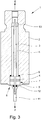
- Fig. 3 shows a further embodiment of a probe holder 1.
- the same elements have the same reference numerals.
- a tight seal 7 is realized between the holder housing 2 and the spacer 4 in the shrunk-on state of the spacer 4.
- the holder housing 2 has a web 9 on the process side, which completely surrounds the opening 6 for receiving the spacer 4 and is bent such that it surrounds the spacer 4.
- a seal 8 is located between the holder housing 2 and the spacer 4 at the end of the spacer inside the housing.
- an adapter 11 is connected to the signal conductor 3, which is used to hold a probe (not shown).
- the signal conductor 3 has a thread
- the adapter 11 has a corresponding mating thread
- the adapter 11 is screwed to the signal conductor 3.
- a seal 12 is arranged between the adapter 11 and the spacer 4 in order to achieve a tight seal.
- the seal 12 achieves its sealing effect by screwing the adapter 13 and the signal conductor 3 together, as a result of which the seal 12 is held between the spacer 4 and the adapter 11.
Landscapes
- Physics & Mathematics (AREA)
- Electromagnetism (AREA)
- Thermal Sciences (AREA)
- Fluid Mechanics (AREA)
- General Physics & Mathematics (AREA)
- Measurement Of Levels Of Liquids Or Fluent Solid Materials (AREA)
- Length Measuring Devices With Unspecified Measuring Means (AREA)
- Geophysics And Detection Of Objects (AREA)
Claims (10)
- Support de sonde (1) destiné à un appareil de mesure de niveau fonctionnant sur le principe du radar, le support de sonde comprenant un boîtier (2), un conducteur de signal (3) destiné à la conduction de signaux d'émission et/ou de réception et un élément d'espacement (4), le conducteur de signal (3) étant guidé depuis l'espace intérieur (5) du boîtier (2) à travers une ouverture côté processus du boîtier jusque dans l'espace extérieur côté processus du boîtier (2), l'élément d'espacement (4) étant disposé dans l'ouverture (6) du boîtier (2) et maintenant le conducteur de signal (3) à distance du boîtier (2) dans l'ouverture (6), l'élément d'espacement (4) étant rétractée dans le boîtier (2) de manière à formé, à l'état rétracté, une fermeture étanche (7) entre le boîtier (2) et l'élément d'espacement (4),
caractérisé en ce que
au moins une garniture d'étanchéité (8) est disposée entre le boîtier (2) et l'élément d'espacement (4), la garniture d'étanchéité (8) étant disposée en tant que garniture d'étanchéité séparé supplémentaire entre des surfaces opposées du boîtier (2) et de l'élément d'espacement (4), lesquelles ne sont pas comprimée l'une sur l'autre ou soumise à une force à cause de la rétraction. - Support de sonde (1) selon la revendication 1, caractérisé en ce que la garniture d'étanchéité (8) est monté à l'extrémité côté intérieur du boîtier de l'élément d'espacement (4), en particulier la garniture d'étanchéité (8) étant conçue comme une garniture d'étanchéité en graphite et/ou une garniture d'étanchéité en or.
- Support de sonde (1) selon l'une des revendications 1 et 2, caractérisé en ce que le boîtier (2) comporte côté processus au moins une nervure (9), en ce que la nervure (9) borde au moins partiellement l'ouverture (6) destinée à recevoir l'élément d'espacement (4) et en ce que la nervure (9) est formé de manière à entourer l'élément d'espacement (4) (côté processus).
- Support de sonde (1) selon l'une des revendications 1 à 3, caractérisé en ce que, à l'état rétracté, l'élément d'espacement (4) est comprimée de telle sorte que le conducteur de signal (3) soit pincé dans l'élément d'espacement (4) de manière à réaliser une fermeture étanche (10) entre le conducteur de signal (3) et l'élément d'espacement (4).
- Support de sonde (1) selon l'une des revendications 1 à 4, caractérisé en ce que l'élément d'espacement (4) est rétractée sur le conducteur de signal (3) de façon à réaliser qu'une fermeture étanche (10) entre le conducteur de signal (3) et l'élément d'espacement (4).
- Support de sonde (1) selon l'une des revendications 1 à 5, caractérisé en ce qu'un adaptateur (11) est relié côté chambre de processus au conducteur de signal (3) et sert à recevoir une sonde.
- Support de sonde (1) selon la revendication 6, caractérisé en ce que le conducteur de signal (3) comporte un filetage, en ce que l'adaptateur (11) comporte un filetage homologue correspondant et en ce que l'adaptateur (11) est vissé au conducteur de signal (3) .
- Support de sonde (1) selon l'une des revendications 6 ou 7, caractérisé en ce que l'adaptateur (11) et le conducteur de signal (3) sont reliés l'un à l'autre de manière à ce que l'adaptateur (11) et l'élément d'espacement (3) forment au moins une surface de contact indirecte et en ce qu'une garniture d'étanchéité (12) est disposée entre l'adaptateur (11) et l'élément d'espacement (3).
- Support de sonde (1) selon l'une des revendications 1 à 8, caractérisé en ce que le boîtier (2) et le conducteur de signal (3) sont en métal.
- Support de sonde (1) selon l'une des revendications 1 à 9, caractérisé en ce que l'élément d'espacement (4) est formé d'un isolant.
Applications Claiming Priority (1)
| Application Number | Priority Date | Filing Date | Title |
|---|---|---|---|
| DE102015116273.3A DE102015116273B4 (de) | 2015-09-25 | 2015-09-25 | Sondenhalterung mit Abstandhalter |
Publications (2)
| Publication Number | Publication Date |
|---|---|
| EP3147635A1 EP3147635A1 (fr) | 2017-03-29 |
| EP3147635B1 true EP3147635B1 (fr) | 2019-12-25 |
Family
ID=56893874
Family Applications (1)
| Application Number | Title | Priority Date | Filing Date |
|---|---|---|---|
| EP16188105.7A Active EP3147635B1 (fr) | 2015-09-25 | 2016-09-09 | Fixation de sonde et ecarteur |
Country Status (5)
| Country | Link |
|---|---|
| US (1) | US10330516B2 (fr) |
| EP (1) | EP3147635B1 (fr) |
| CN (1) | CN106979809B (fr) |
| CA (1) | CA2942952C (fr) |
| DE (1) | DE102015116273B4 (fr) |
Families Citing this family (2)
| Publication number | Priority date | Publication date | Assignee | Title |
|---|---|---|---|---|
| US9921096B2 (en) * | 2014-09-10 | 2018-03-20 | Honeywell International Inc. | Mechanical system for centering and holding a coax conductor in the center of an outer conductor |
| DE102015220578A1 (de) * | 2015-10-21 | 2017-04-27 | Vega Grieshaber Kg | Sondenendvorrichtung und Verfahren zum Herstellen einer Sondenendvorrichtung |
Citations (1)
| Publication number | Priority date | Publication date | Assignee | Title |
|---|---|---|---|---|
| EP0943902A1 (fr) * | 1998-03-18 | 1999-09-22 | VEGA Grieshaber GmbH & Co. | Capteur du niveau à microondes capable de fonctionner à températures hautes et/ou pressions hautes et/ou dans un environnement chimiquement |
Family Cites Families (17)
| Publication number | Priority date | Publication date | Assignee | Title |
|---|---|---|---|---|
| DE10027228B4 (de) * | 2000-05-31 | 2007-05-16 | Endress & Hauser Gmbh & Co Kg | Vorrichtung zur Bestimmung und/oder Überwachung des Füllstandes eines Füllguts in einem Behälter |
| DE10058026A1 (de) * | 2000-11-23 | 2002-05-29 | Grieshaber Vega Kg | Durchführung für ein elektrisches Hochfrequenzsignal und Füllstandmeßeinrichtung mit einer solchen Durchführung |
| DE10159394A1 (de) * | 2001-12-04 | 2003-06-12 | Endress & Hauser Gmbh & Co Kg | Füllstandsmessgerät |
| US7401511B2 (en) * | 2003-12-12 | 2008-07-22 | Vega Grieshaber Kg | Coaxial gapless guide-through assembly for a filing level sensor |
| US7255002B2 (en) * | 2005-04-07 | 2007-08-14 | Rosemount, Inc. | Tank seal for guided wave radar level measurement |
| US7467548B2 (en) * | 2005-10-14 | 2008-12-23 | Rosemount Tank Radar Ab | Radar level gauge system and coupling |
| DE102006003742A1 (de) * | 2006-01-25 | 2007-08-02 | Endress + Hauser Gmbh + Co. Kg | Vorrichtung zur Ermittlung und Überwachung des Füllstandes eines Mediums in einem Behälter |
| US7992437B2 (en) * | 2006-02-14 | 2011-08-09 | Savannah River Nuclear Solutions, Llc | Liquid level detector |
| DE102006053399A1 (de) * | 2006-11-10 | 2008-05-15 | Endress + Hauser Gmbh + Co. Kg | Messsonde für ein Messgerät |
| ATE521111T1 (de) * | 2008-02-20 | 2011-09-15 | Grieshaber Vega Kg | Leiterdurchführung, gehäusevorrichtung, feldgerät und verfahren zur herstellung einer leiterdruchführung |
| US7636059B1 (en) * | 2008-06-04 | 2009-12-22 | Rosemount Tank Radar Ab | Impedance matched guided wave radar level gauge system |
| WO2010105654A1 (fr) * | 2009-03-16 | 2010-09-23 | Kfa Sarl | Connexion d'interface coaxiale, système de détection haute fréquence doté d'une telle connexion d'interface et procédé de fabrication de ladite connexion d'interface |
| HUE052056T2 (hu) * | 2011-05-26 | 2021-04-28 | Grieshaber Vega Kg | Mérõrendszer nyomásálló átvezetéssel |
| EP2584652B1 (fr) * | 2011-10-21 | 2013-12-04 | Siemens Aktiengesellschaft | Antenne à cornet pour dispositif radar |
| DE102012014267B4 (de) * | 2012-07-19 | 2020-12-24 | Krohne S.A. | Nach dem Radar-Prinzip arbeitendes Füllstandmessgerät |
| US9476753B2 (en) * | 2014-03-28 | 2016-10-25 | Honeywell International Inc. | Feed-through for GWR measurements in tanks |
| US9970806B2 (en) * | 2015-04-30 | 2018-05-15 | Rosemount Tank Radar Ab | Single conductor probe radar level gauge system and method for a tank having a tubular mounting structure |
-
2015
- 2015-09-25 DE DE102015116273.3A patent/DE102015116273B4/de not_active Withdrawn - After Issue
-
2016
- 2016-09-09 EP EP16188105.7A patent/EP3147635B1/fr active Active
- 2016-09-23 US US15/273,911 patent/US10330516B2/en active Active
- 2016-09-23 CA CA2942952A patent/CA2942952C/fr active Active
- 2016-09-23 CN CN201610843478.XA patent/CN106979809B/zh active Active
Patent Citations (1)
| Publication number | Priority date | Publication date | Assignee | Title |
|---|---|---|---|---|
| EP0943902A1 (fr) * | 1998-03-18 | 1999-09-22 | VEGA Grieshaber GmbH & Co. | Capteur du niveau à microondes capable de fonctionner à températures hautes et/ou pressions hautes et/ou dans un environnement chimiquement |
Also Published As
| Publication number | Publication date |
|---|---|
| CN106979809A (zh) | 2017-07-25 |
| US10330516B2 (en) | 2019-06-25 |
| EP3147635A1 (fr) | 2017-03-29 |
| CA2942952A1 (fr) | 2017-03-25 |
| DE102015116273A1 (de) | 2017-03-30 |
| CN106979809B (zh) | 2020-09-29 |
| US20170089747A1 (en) | 2017-03-30 |
| CA2942952C (fr) | 2022-10-11 |
| DE102015116273B4 (de) | 2017-04-20 |
Similar Documents
| Publication | Publication Date | Title |
|---|---|---|
| EP1156302B1 (fr) | Dispositif de mesure de niveau | |
| DE10308495A1 (de) | Vorrichtung zur Bestimmung und/oder Überwachung des Füllstands eines Mediums in einem Behälter | |
| EP2027441B1 (fr) | Dispositif de mesure de niveau | |
| EP2687830B1 (fr) | Procédé de surveillance de l'état d'un appareil de mesure du niveau de remplissage fonctionnant selon le principe du radar et appareil de mesure du niveau de remplissage correspondant | |
| EP2340420B1 (fr) | Appareil de mesure du niveau de remplissage | |
| EP2652470B1 (fr) | Partie intérieure d'un tube de protection pour un thermomètre à tube de protection | |
| DE19542525C2 (de) | Mikrowellenfenster | |
| EP2698869A1 (fr) | Fenêtre de micro-ondes et système de mesure du niveau de remplissage fonctionnant selon le principe de radar | |
| EP2003730B1 (fr) | Antenne pour un radar de niveau de remplissage pour application à haute température et/ou haute pression | |
| DE102012109308A1 (de) | Füllstandsüberwachungssystem und Durchflussmessgerät | |
| DE102012103493A1 (de) | Vorrichtung zur Bestimmung des Füllstandes eines Füllguts in einem Behälter | |
| DE102016124982A1 (de) | Temperaturbeständiges Füllstandsmessgerät | |
| DE102015113237A1 (de) | Temperaturmessgerät zur Messung der Temperatur eines in einem Behälter befindlichen Mediums | |
| DE102016212220A1 (de) | Anordnung aus einem Messgerät und einem Behälter | |
| DE102014107781A1 (de) | Vorrichtung zur Bestimmung oder Überwachung einer physikalischen oder chemischen Prozessgröße | |
| DE19532646A1 (de) | Füllstandsmeßgerät | |
| DE102015116273B4 (de) | Sondenhalterung mit Abstandhalter | |
| EP2414791B1 (fr) | Dispositif d'étanchéité pour un dispositif de mesure de niveau d'un liquide dans un reservoir sous pression d'une centrale nucleaire | |
| DE102014118867A1 (de) | Nach dem Radarprinzip arbeitendes Füllstandmessgerät und Übertragungsstrecke für ein Füllstandmessgerät | |
| WO2020104167A1 (fr) | Sonde de mesure permettant de déterminer ou de surveiller une grandeur de processus physique ou chimique d'un milieu | |
| EP4038352B1 (fr) | Adaptateur hygiénique pour instrument de terrain | |
| DE10021059B4 (de) | Fühler | |
| EP3824257B1 (fr) | Dispositif de mesure de niveau de remplissage | |
| EP3693712A1 (fr) | Capteur permettant de déterminer une grandeur de processus | |
| DE102014102054A1 (de) | Füllstandsensor mit Elektrodenüberwachung |
Legal Events
| Date | Code | Title | Description |
|---|---|---|---|
| PUAI | Public reference made under article 153(3) epc to a published international application that has entered the european phase |
Free format text: ORIGINAL CODE: 0009012 |
|
| STAA | Information on the status of an ep patent application or granted ep patent |
Free format text: STATUS: THE APPLICATION HAS BEEN PUBLISHED |
|
| AK | Designated contracting states |
Kind code of ref document: A1 Designated state(s): AL AT BE BG CH CY CZ DE DK EE ES FI FR GB GR HR HU IE IS IT LI LT LU LV MC MK MT NL NO PL PT RO RS SE SI SK SM TR |
|
| AX | Request for extension of the european patent |
Extension state: BA ME |
|
| STAA | Information on the status of an ep patent application or granted ep patent |
Free format text: STATUS: REQUEST FOR EXAMINATION WAS MADE |
|
| 17P | Request for examination filed |
Effective date: 20170413 |
|
| RBV | Designated contracting states (corrected) |
Designated state(s): AL AT BE BG CH CY CZ DE DK EE ES FI FR GB GR HR HU IE IS IT LI LT LU LV MC MK MT NL NO PL PT RO RS SE SI SK SM TR |
|
| STAA | Information on the status of an ep patent application or granted ep patent |
Free format text: STATUS: EXAMINATION IS IN PROGRESS |
|
| 17Q | First examination report despatched |
Effective date: 20180523 |
|
| GRAP | Despatch of communication of intention to grant a patent |
Free format text: ORIGINAL CODE: EPIDOSNIGR1 |
|
| STAA | Information on the status of an ep patent application or granted ep patent |
Free format text: STATUS: GRANT OF PATENT IS INTENDED |
|
| GRAS | Grant fee paid |
Free format text: ORIGINAL CODE: EPIDOSNIGR3 |
|
| INTG | Intention to grant announced |
Effective date: 20190828 |
|
| GRAA | (expected) grant |
Free format text: ORIGINAL CODE: 0009210 |
|
| STAA | Information on the status of an ep patent application or granted ep patent |
Free format text: STATUS: THE PATENT HAS BEEN GRANTED |
|
| AK | Designated contracting states |
Kind code of ref document: B1 Designated state(s): AL AT BE BG CH CY CZ DE DK EE ES FI FR GB GR HR HU IE IS IT LI LT LU LV MC MK MT NL NO PL PT RO RS SE SI SK SM TR |
|
| REG | Reference to a national code |
Ref country code: GB Ref legal event code: FG4D Free format text: NOT ENGLISH |
|
| REG | Reference to a national code |
Ref country code: CH Ref legal event code: EP |
|
| REG | Reference to a national code |
Ref country code: DE Ref legal event code: R096 Ref document number: 502016008121 Country of ref document: DE |
|
| REG | Reference to a national code |
Ref country code: AT Ref legal event code: REF Ref document number: 1217633 Country of ref document: AT Kind code of ref document: T Effective date: 20200115 |
|
| REG | Reference to a national code |
Ref country code: IE Ref legal event code: FG4D Free format text: LANGUAGE OF EP DOCUMENT: GERMAN |
|
| REG | Reference to a national code |
Ref country code: NL Ref legal event code: MP Effective date: 20191225 |
|
| PG25 | Lapsed in a contracting state [announced via postgrant information from national office to epo] |
Ref country code: NO Free format text: LAPSE BECAUSE OF FAILURE TO SUBMIT A TRANSLATION OF THE DESCRIPTION OR TO PAY THE FEE WITHIN THE PRESCRIBED TIME-LIMIT Effective date: 20200325 Ref country code: GR Free format text: LAPSE BECAUSE OF FAILURE TO SUBMIT A TRANSLATION OF THE DESCRIPTION OR TO PAY THE FEE WITHIN THE PRESCRIBED TIME-LIMIT Effective date: 20200326 Ref country code: LT Free format text: LAPSE BECAUSE OF FAILURE TO SUBMIT A TRANSLATION OF THE DESCRIPTION OR TO PAY THE FEE WITHIN THE PRESCRIBED TIME-LIMIT Effective date: 20191225 Ref country code: LV Free format text: LAPSE BECAUSE OF FAILURE TO SUBMIT A TRANSLATION OF THE DESCRIPTION OR TO PAY THE FEE WITHIN THE PRESCRIBED TIME-LIMIT Effective date: 20191225 Ref country code: SE Free format text: LAPSE BECAUSE OF FAILURE TO SUBMIT A TRANSLATION OF THE DESCRIPTION OR TO PAY THE FEE WITHIN THE PRESCRIBED TIME-LIMIT Effective date: 20191225 Ref country code: FI Free format text: LAPSE BECAUSE OF FAILURE TO SUBMIT A TRANSLATION OF THE DESCRIPTION OR TO PAY THE FEE WITHIN THE PRESCRIBED TIME-LIMIT Effective date: 20191225 Ref country code: BG Free format text: LAPSE BECAUSE OF FAILURE TO SUBMIT A TRANSLATION OF THE DESCRIPTION OR TO PAY THE FEE WITHIN THE PRESCRIBED TIME-LIMIT Effective date: 20200325 |
|
| REG | Reference to a national code |
Ref country code: LT Ref legal event code: MG4D |
|
| PG25 | Lapsed in a contracting state [announced via postgrant information from national office to epo] |
Ref country code: RS Free format text: LAPSE BECAUSE OF FAILURE TO SUBMIT A TRANSLATION OF THE DESCRIPTION OR TO PAY THE FEE WITHIN THE PRESCRIBED TIME-LIMIT Effective date: 20191225 Ref country code: HR Free format text: LAPSE BECAUSE OF FAILURE TO SUBMIT A TRANSLATION OF THE DESCRIPTION OR TO PAY THE FEE WITHIN THE PRESCRIBED TIME-LIMIT Effective date: 20191225 |
|
| PG25 | Lapsed in a contracting state [announced via postgrant information from national office to epo] |
Ref country code: AL Free format text: LAPSE BECAUSE OF FAILURE TO SUBMIT A TRANSLATION OF THE DESCRIPTION OR TO PAY THE FEE WITHIN THE PRESCRIBED TIME-LIMIT Effective date: 20191225 |
|
| PG25 | Lapsed in a contracting state [announced via postgrant information from national office to epo] |
Ref country code: EE Free format text: LAPSE BECAUSE OF FAILURE TO SUBMIT A TRANSLATION OF THE DESCRIPTION OR TO PAY THE FEE WITHIN THE PRESCRIBED TIME-LIMIT Effective date: 20191225 Ref country code: PT Free format text: LAPSE BECAUSE OF FAILURE TO SUBMIT A TRANSLATION OF THE DESCRIPTION OR TO PAY THE FEE WITHIN THE PRESCRIBED TIME-LIMIT Effective date: 20200520 Ref country code: NL Free format text: LAPSE BECAUSE OF FAILURE TO SUBMIT A TRANSLATION OF THE DESCRIPTION OR TO PAY THE FEE WITHIN THE PRESCRIBED TIME-LIMIT Effective date: 20191225 Ref country code: RO Free format text: LAPSE BECAUSE OF FAILURE TO SUBMIT A TRANSLATION OF THE DESCRIPTION OR TO PAY THE FEE WITHIN THE PRESCRIBED TIME-LIMIT Effective date: 20191225 Ref country code: CZ Free format text: LAPSE BECAUSE OF FAILURE TO SUBMIT A TRANSLATION OF THE DESCRIPTION OR TO PAY THE FEE WITHIN THE PRESCRIBED TIME-LIMIT Effective date: 20191225 |
|
| PG25 | Lapsed in a contracting state [announced via postgrant information from national office to epo] |
Ref country code: SM Free format text: LAPSE BECAUSE OF FAILURE TO SUBMIT A TRANSLATION OF THE DESCRIPTION OR TO PAY THE FEE WITHIN THE PRESCRIBED TIME-LIMIT Effective date: 20191225 Ref country code: SK Free format text: LAPSE BECAUSE OF FAILURE TO SUBMIT A TRANSLATION OF THE DESCRIPTION OR TO PAY THE FEE WITHIN THE PRESCRIBED TIME-LIMIT Effective date: 20191225 Ref country code: IS Free format text: LAPSE BECAUSE OF FAILURE TO SUBMIT A TRANSLATION OF THE DESCRIPTION OR TO PAY THE FEE WITHIN THE PRESCRIBED TIME-LIMIT Effective date: 20200425 |
|
| REG | Reference to a national code |
Ref country code: DE Ref legal event code: R097 Ref document number: 502016008121 Country of ref document: DE |
|
| PG25 | Lapsed in a contracting state [announced via postgrant information from national office to epo] |
Ref country code: DK Free format text: LAPSE BECAUSE OF FAILURE TO SUBMIT A TRANSLATION OF THE DESCRIPTION OR TO PAY THE FEE WITHIN THE PRESCRIBED TIME-LIMIT Effective date: 20191225 Ref country code: ES Free format text: LAPSE BECAUSE OF FAILURE TO SUBMIT A TRANSLATION OF THE DESCRIPTION OR TO PAY THE FEE WITHIN THE PRESCRIBED TIME-LIMIT Effective date: 20191225 |
|
| PLBE | No opposition filed within time limit |
Free format text: ORIGINAL CODE: 0009261 |
|
| STAA | Information on the status of an ep patent application or granted ep patent |
Free format text: STATUS: NO OPPOSITION FILED WITHIN TIME LIMIT |
|
| PG25 | Lapsed in a contracting state [announced via postgrant information from national office to epo] |
Ref country code: SI Free format text: LAPSE BECAUSE OF FAILURE TO SUBMIT A TRANSLATION OF THE DESCRIPTION OR TO PAY THE FEE WITHIN THE PRESCRIBED TIME-LIMIT Effective date: 20191225 |
|
| 26N | No opposition filed |
Effective date: 20200928 |
|
| PG25 | Lapsed in a contracting state [announced via postgrant information from national office to epo] |
Ref country code: IT Free format text: LAPSE BECAUSE OF FAILURE TO SUBMIT A TRANSLATION OF THE DESCRIPTION OR TO PAY THE FEE WITHIN THE PRESCRIBED TIME-LIMIT Effective date: 20191225 |
|
| PG25 | Lapsed in a contracting state [announced via postgrant information from national office to epo] |
Ref country code: PL Free format text: LAPSE BECAUSE OF FAILURE TO SUBMIT A TRANSLATION OF THE DESCRIPTION OR TO PAY THE FEE WITHIN THE PRESCRIBED TIME-LIMIT Effective date: 20191225 |
|
| PG25 | Lapsed in a contracting state [announced via postgrant information from national office to epo] |
Ref country code: MC Free format text: LAPSE BECAUSE OF FAILURE TO SUBMIT A TRANSLATION OF THE DESCRIPTION OR TO PAY THE FEE WITHIN THE PRESCRIBED TIME-LIMIT Effective date: 20191225 |
|
| REG | Reference to a national code |
Ref country code: BE Ref legal event code: MM Effective date: 20200930 |
|
| PG25 | Lapsed in a contracting state [announced via postgrant information from national office to epo] |
Ref country code: LU Free format text: LAPSE BECAUSE OF NON-PAYMENT OF DUE FEES Effective date: 20200909 |
|
| PG25 | Lapsed in a contracting state [announced via postgrant information from national office to epo] |
Ref country code: IE Free format text: LAPSE BECAUSE OF NON-PAYMENT OF DUE FEES Effective date: 20200909 Ref country code: BE Free format text: LAPSE BECAUSE OF NON-PAYMENT OF DUE FEES Effective date: 20200930 |
|
| PG25 | Lapsed in a contracting state [announced via postgrant information from national office to epo] |
Ref country code: TR Free format text: LAPSE BECAUSE OF FAILURE TO SUBMIT A TRANSLATION OF THE DESCRIPTION OR TO PAY THE FEE WITHIN THE PRESCRIBED TIME-LIMIT Effective date: 20191225 Ref country code: MT Free format text: LAPSE BECAUSE OF FAILURE TO SUBMIT A TRANSLATION OF THE DESCRIPTION OR TO PAY THE FEE WITHIN THE PRESCRIBED TIME-LIMIT Effective date: 20191225 Ref country code: CY Free format text: LAPSE BECAUSE OF FAILURE TO SUBMIT A TRANSLATION OF THE DESCRIPTION OR TO PAY THE FEE WITHIN THE PRESCRIBED TIME-LIMIT Effective date: 20191225 |
|
| PG25 | Lapsed in a contracting state [announced via postgrant information from national office to epo] |
Ref country code: MK Free format text: LAPSE BECAUSE OF FAILURE TO SUBMIT A TRANSLATION OF THE DESCRIPTION OR TO PAY THE FEE WITHIN THE PRESCRIBED TIME-LIMIT Effective date: 20191225 |
|
| REG | Reference to a national code |
Ref country code: AT Ref legal event code: MM01 Ref document number: 1217633 Country of ref document: AT Kind code of ref document: T Effective date: 20210909 |
|
| PG25 | Lapsed in a contracting state [announced via postgrant information from national office to epo] |
Ref country code: AT Free format text: LAPSE BECAUSE OF NON-PAYMENT OF DUE FEES Effective date: 20210909 |
|
| P01 | Opt-out of the competence of the unified patent court (upc) registered |
Effective date: 20230607 |
|
| PGFP | Annual fee paid to national office [announced via postgrant information from national office to epo] |
Ref country code: GB Payment date: 20240729 Year of fee payment: 9 |
|
| REG | Reference to a national code |
Ref country code: CH Ref legal event code: U11 Free format text: ST27 STATUS EVENT CODE: U-0-0-U10-U11 (AS PROVIDED BY THE NATIONAL OFFICE) Effective date: 20251001 |
|
| PGFP | Annual fee paid to national office [announced via postgrant information from national office to epo] |
Ref country code: FR Payment date: 20250922 Year of fee payment: 10 |
|
| PGFP | Annual fee paid to national office [announced via postgrant information from national office to epo] |
Ref country code: DE Payment date: 20251110 Year of fee payment: 10 |
|
| PGFP | Annual fee paid to national office [announced via postgrant information from national office to epo] |
Ref country code: CH Payment date: 20251001 Year of fee payment: 10 |