EP3147650A1 - Nebensprechkorrektur in mulitplex-analyse einer biologischen probe - Google Patents
Nebensprechkorrektur in mulitplex-analyse einer biologischen probe Download PDFInfo
- Publication number
- EP3147650A1 EP3147650A1 EP15186210.9A EP15186210A EP3147650A1 EP 3147650 A1 EP3147650 A1 EP 3147650A1 EP 15186210 A EP15186210 A EP 15186210A EP 3147650 A1 EP3147650 A1 EP 3147650A1
- Authority
- EP
- European Patent Office
- Prior art keywords
- fluorescent
- fluorescence
- microparticles
- spe
- microparticle
- Prior art date
- Legal status (The legal status is an assumption and is not a legal conclusion. Google has not performed a legal analysis and makes no representation as to the accuracy of the status listed.)
- Withdrawn
Links
Images


Classifications
-
- G—PHYSICS
- G01—MEASURING; TESTING
- G01N—INVESTIGATING OR ANALYSING MATERIALS BY DETERMINING THEIR CHEMICAL OR PHYSICAL PROPERTIES
- G01N21/00—Investigating or analysing materials by the use of optical means, i.e. using sub-millimetre waves, infrared, visible or ultraviolet light
- G01N21/62—Systems in which the material investigated is excited whereby it emits light or causes a change in wavelength of the incident light
- G01N21/63—Systems in which the material investigated is excited whereby it emits light or causes a change in wavelength of the incident light optically excited
- G01N21/64—Fluorescence; Phosphorescence
- G01N21/645—Specially adapted constructive features of fluorimeters
- G01N21/6452—Individual samples arranged in a regular 2D-array, e.g. multiwell plates
-
- B—PERFORMING OPERATIONS; TRANSPORTING
- B01—PHYSICAL OR CHEMICAL PROCESSES OR APPARATUS IN GENERAL
- B01L—CHEMICAL OR PHYSICAL LABORATORY APPARATUS FOR GENERAL USE
- B01L3/00—Containers or dishes for laboratory use, e.g. laboratory glassware; Droppers
- B01L3/50—Containers for the purpose of retaining a material to be analysed, e.g. test tubes
- B01L3/502—Containers for the purpose of retaining a material to be analysed, e.g. test tubes with fluid transport, e.g. in multi-compartment structures
- B01L3/5027—Containers for the purpose of retaining a material to be analysed, e.g. test tubes with fluid transport, e.g. in multi-compartment structures by integrated microfluidic structures, i.e. dimensions of channels and chambers are such that surface tension forces are important, e.g. lab-on-a-chip
- B01L3/502715—Containers for the purpose of retaining a material to be analysed, e.g. test tubes with fluid transport, e.g. in multi-compartment structures by integrated microfluidic structures, i.e. dimensions of channels and chambers are such that surface tension forces are important, e.g. lab-on-a-chip characterised by interfacing components, e.g. fluidic, electrical, optical or mechanical interfaces
-
- G—PHYSICS
- G01—MEASURING; TESTING
- G01N—INVESTIGATING OR ANALYSING MATERIALS BY DETERMINING THEIR CHEMICAL OR PHYSICAL PROPERTIES
- G01N21/00—Investigating or analysing materials by the use of optical means, i.e. using sub-millimetre waves, infrared, visible or ultraviolet light
- G01N21/62—Systems in which the material investigated is excited whereby it emits light or causes a change in wavelength of the incident light
- G01N21/63—Systems in which the material investigated is excited whereby it emits light or causes a change in wavelength of the incident light optically excited
- G01N21/64—Fluorescence; Phosphorescence
- G01N21/6408—Fluorescence; Phosphorescence with measurement of decay time, time resolved fluorescence
-
- G—PHYSICS
- G01—MEASURING; TESTING
- G01N—INVESTIGATING OR ANALYSING MATERIALS BY DETERMINING THEIR CHEMICAL OR PHYSICAL PROPERTIES
- G01N21/00—Investigating or analysing materials by the use of optical means, i.e. using sub-millimetre waves, infrared, visible or ultraviolet light
- G01N21/62—Systems in which the material investigated is excited whereby it emits light or causes a change in wavelength of the incident light
- G01N21/63—Systems in which the material investigated is excited whereby it emits light or causes a change in wavelength of the incident light optically excited
- G01N21/64—Fluorescence; Phosphorescence
- G01N21/6428—Measuring fluorescence of fluorescent products of reactions or of fluorochrome labelled reactive substances, e.g. measuring quenching effects, using measuring "optrodes"
-
- G—PHYSICS
- G01—MEASURING; TESTING
- G01N—INVESTIGATING OR ANALYSING MATERIALS BY DETERMINING THEIR CHEMICAL OR PHYSICAL PROPERTIES
- G01N21/00—Investigating or analysing materials by the use of optical means, i.e. using sub-millimetre waves, infrared, visible or ultraviolet light
- G01N21/62—Systems in which the material investigated is excited whereby it emits light or causes a change in wavelength of the incident light
- G01N21/63—Systems in which the material investigated is excited whereby it emits light or causes a change in wavelength of the incident light optically excited
- G01N21/64—Fluorescence; Phosphorescence
- G01N21/645—Specially adapted constructive features of fluorimeters
- G01N21/6456—Spatial resolved fluorescence measurements; Imaging
-
- B—PERFORMING OPERATIONS; TRANSPORTING
- B01—PHYSICAL OR CHEMICAL PROCESSES OR APPARATUS IN GENERAL
- B01L—CHEMICAL OR PHYSICAL LABORATORY APPARATUS FOR GENERAL USE
- B01L2300/00—Additional constructional details
- B01L2300/06—Auxiliary integrated devices, integrated components
- B01L2300/0627—Sensor or part of a sensor is integrated
-
- G—PHYSICS
- G01—MEASURING; TESTING
- G01J—MEASUREMENT OF INTENSITY, VELOCITY, SPECTRAL CONTENT, POLARISATION, PHASE OR PULSE CHARACTERISTICS OF INFRARED, VISIBLE OR ULTRAVIOLET LIGHT; COLORIMETRY; RADIATION PYROMETRY
- G01J3/00—Spectrometry; Spectrophotometry; Monochromators; Measuring colours
- G01J3/28—Investigating the spectrum
- G01J3/44—Raman spectrometry; Scattering spectrometry ; Fluorescence spectrometry
- G01J3/4406—Fluorescence spectrometry
-
- G—PHYSICS
- G01—MEASURING; TESTING
- G01N—INVESTIGATING OR ANALYSING MATERIALS BY DETERMINING THEIR CHEMICAL OR PHYSICAL PROPERTIES
- G01N21/00—Investigating or analysing materials by the use of optical means, i.e. using sub-millimetre waves, infrared, visible or ultraviolet light
- G01N21/01—Arrangements or apparatus for facilitating the optical investigation
- G01N21/03—Cuvette constructions
- G01N21/05—Flow-through cuvettes
- G01N2021/058—Flat flow cell
-
- G—PHYSICS
- G01—MEASURING; TESTING
- G01N—INVESTIGATING OR ANALYSING MATERIALS BY DETERMINING THEIR CHEMICAL OR PHYSICAL PROPERTIES
- G01N21/00—Investigating or analysing materials by the use of optical means, i.e. using sub-millimetre waves, infrared, visible or ultraviolet light
- G01N21/62—Systems in which the material investigated is excited whereby it emits light or causes a change in wavelength of the incident light
- G01N21/63—Systems in which the material investigated is excited whereby it emits light or causes a change in wavelength of the incident light optically excited
- G01N21/64—Fluorescence; Phosphorescence
- G01N21/6428—Measuring fluorescence of fluorescent products of reactions or of fluorochrome labelled reactive substances, e.g. measuring quenching effects, using measuring "optrodes"
- G01N2021/6439—Measuring fluorescence of fluorescent products of reactions or of fluorochrome labelled reactive substances, e.g. measuring quenching effects, using measuring "optrodes" with indicators, stains, dyes, tags, labels, marks
- G01N2021/6441—Measuring fluorescence of fluorescent products of reactions or of fluorochrome labelled reactive substances, e.g. measuring quenching effects, using measuring "optrodes" with indicators, stains, dyes, tags, labels, marks with two or more labels
Definitions
- the invention relates to biological multiplexing analysis, in particular in diagnosis of complex diseases based on detection of multiple biomarkers in a biological sample.
- multiplexing technologies may measure, within a single assay, tens to thousands of different biomolecules, e.g., proteins or nucleic acids, from a single biological sample using identical conditions.
- capture molecules of different types e.g. antibodies, target proteins, peptides or nucleic acids
- capture molecules are provided in an assay apparatus filled with the sample, each type of capture molecule being designed to form with the biomarker to be searched in the sample a particular fluorescently labeled complex (usually referred as "the targeted fluorescent labeled biomarker").
- One main issue of multiplexing techniques is to determine during the single assay the fluorescence originating from a single type of fluorescently labeled biomarkers bound to their complementary capture molecules (hereafter "individual fluorescence").
- multiplexing technologies are available, each being usually classified according to its specific encoding strategy addressing this issue.
- the most popular commercially available multiplexing technologies are array-based and bead-based.
- array-based technologies capture molecules are bound on a panel in a known arrangement to form a 2D array of "capture spots", each dedicated to the capture of a particular biomarker.
- Such planar arrays thus rely on x-y-coordinates of the capture spots to determine the fluorescence of each biomarker.
- Bead-based technologies are based on spectral encoding in which the color and intensity allows discriminating each bead population. They have proven to be highly flexible and scalable.
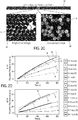
- the encoded microparticles 10, or “carriers” are disk-shaped, 40 ⁇ m in diameter and 10 ⁇ m in height, and are produced from silicon wafers, e.g. using MEMS manufacturing technology.
- the periphery of each microparticle 10 is unambiguously encoded using a 10-digit binary code Id m 12, or "identifier", formed by the presence or absence of holes 14.
- Capture molecules are bound to both faces of the microparticles 10, the latter thus acting as a solid support for a multitude of possible capture molecules, including antibodies, target proteins, peptides, nucleic acids or other biomolecules. More particularly, a single type of capture molecules (i.e. capture molecules dedicated to the capture of a particular biomarker) is tethered onto microparticles sharing the same code Id m .
- the cartridge 20, or "assay plate” features a plurality of microscale channels 22 able to host encoded microparticle mixes and thus enabling running multiple samples simultaneously or sequentially (i.e. at different dates).
- Each channel 22 is made of transparent walls and connects an inlet well 24 and an outlet well 26 which enable the pressurization of the channel 22 above the atmospheric pressure, enabling the microfluidic operation of the channel.
- the channels 22 are at least 5 times, e.g. 10 times, wider than the microparticles' diameter, and include each a filter structure to restrain the microparticles in a detection zone of the channel.
- the height of the channels is optimized for efficient microparticle loading and tiling.
- the shallow channel height prevents microparticles from overlapping each other so that microparticles are arranged in the channel in a monolayer arrangement with one of their faces fully acquirable for imaging purpose.
- This monolayer arrangement of microparticles in the channel thus enables the use of high resolution imaging for both decoding and fluorescence quantification.
- Each channel can be loaded with up to thousands of microparticles, a fully loaded channel enabling a multiplexing of more than one hundred different biomarkers with tens of microparticles for each biomarker to be searched for.
- a microparticle mix loaded in a channel includes multiple microparticles sharing an identical code, thereby forming a population which provides measurement redundancy for statistical confidence.
- Instrumentation aims at acquiring images of the channel, at controlling the fluid actuation and the temperature in the channels and at analyzing acquired images. More particularly, instrumentation comprises:
- a multiplex analysis embodied by the aforementioned multiplexing technology thus consists in:
- the computed concentrations are then displayed to the user and/or stored on a digital memory (e.g.: the one of the computing unit).
- a digital memory e.g.: the one of the computing unit.
- This multiplexing technology allows (i) short assay times and high reproducibility thanks to reaction-limited binding regime, (ii) dynamic control of assay conditions and real-time binding monitoring allowing optimization of multiple parameters within a single assay run, (iii) compatibility with various immunoassay formats such as co-flowing the samples and detection antibodies simultaneously and hence simplifying workflows, (iv) analyte quantification based on initial binding rates leading to increased system dynamic range and (v) high sensitivity via enhanced fluorescence collection, (vi) opportunity to run monoplex (i.e. providing only one type of capture molecules for the quantitative measure of a particular biomarker) assay if desired.
- biomarker concentration [ b ] which is computed from multiplex assay data
- biomarker concentration [ b ] computed from monoplex assay data
- One aim of the invention is to propose, in a multiplexing analysis, computation of microparticle fluorescences that corrects the difference between multiplex and monoplex assays.
- one object of the invention is a method for determining fluorescences ⁇ i s p e i ⁇ 1 , 2 , ... , I of a set of I fluorescent microparticles ⁇ ⁇ P i ⁇ i ⁇ ⁇ 1,2,..., I ⁇ of a multiplexing analysis, said microparticles being in a monolayer arrangement, the method comprising:
- the method comprises computing the fluorescence ⁇ i spe of said fluorescent microparticle ⁇ P i by correcting its first fluorescence ⁇ i meas by a cross-talk fluorescence contribution ⁇ i cross in said first fluorescence ⁇ i meas from other fluorescent microparticles ⁇ ⁇ P j ⁇ j ⁇ i in the set of fluorescent microparticles ⁇ ⁇ P i ⁇ i ⁇ ⁇ 1,2,..., I ⁇ .
- the portion of the acquired image corresponding to a microparticle ⁇ P j does not strictly correspond to the light produced by said microparticle.
- Each microparticle produces light that scatters and thus superimposes to the light of other microparticles.
- Drawing a parallel with imagery there is a "cross-talk" effect between the microparticles.
- the cross-talk effect may be observed when at least two populations of microparticles of different fluorescences (e.g. a dark population and a bright population) are mixed together. For example, when the difference in fluorescence is large enough between the two populations, an increase in fluorescence is observed on some microparticles of the darker populations that are in the neighborhood of microparticles of the brighter population.
- Cross-talk may also exist in monoplex assay.
- the computation of the fluorescence value ⁇ i spe comprises:
- the cross-talk effect may be modelled by the sum of isotropic decay profiles. This implies that one may consider a microparticle independently from the other for computing its contribution and that the fluorescence scattered by a microparticle depends only on the distance from the microparticle and the fluorescence on the microparticle.
- the unitary cross-talk fluorescence contributions ⁇ ij corresponds for example to the normalized fluorescence that a microparticle generates and is computed based on constant parameters determined beforehand, for example by the manufacturer of a multiplex analyzer, and stored in the memory of the analyzer.
- the method comprises:
- the computation is based on a two particular reductions, as it will be discussed later, which enables a simple, while very accurate, correction of the cross-talk effect.
- Sum of exponential functions is an effective way to model the unitary cross-talk fluorescence contribution ⁇ ij , while at the same time offering flexibility of convex optimization for computing parameters ⁇ n , k n and ⁇ n .
- three exponentials are sufficient to compute ⁇ ij .
- each fluorescent microparticle ⁇ P i of the set of fluorescent microparticles ⁇ ⁇ P i ⁇ i ⁇ ⁇ 1,2,..., I ⁇ comprises an identifier Id m ( i ) of a set of M different unique identifiers ⁇ id m ⁇ m ⁇ ⁇ 1,2,..., M ⁇ , said identifying Id M ( i ) being readable through processing of a digitial image of said fluorescent microparticle ⁇ P i , and in that the method further comprises:
- each fluorescent microparticle ⁇ P i of the set of fluorescent microparticles ⁇ ⁇ P i ⁇ i ⁇ ⁇ 1,2,..., I ⁇ comprises a surface coated with fluorescent complexes uniquely associated to the identifying Id m ( i ) of said fluorescent microparticle ⁇ P i , said complexes comprising first non-fluorescent molecules fixed to the microparticles and second fluorescent molecules bound to the first non-fluorescent molecules.
- microparticles have equal dimension.
- the method comprises:
- Another object of the invention is a system for embodying the aforementioned method, in particular a system for determining fluorescences ⁇ i s p e i ⁇ 1 , 2 , ... , I of a set of I fluorescent microparticles ⁇ ⁇ P i ⁇ i ⁇ ⁇ 1,2,..., I ⁇ comprising:
- the embodiment differs from the EvalutionTM system by supplementary processing according to the invention.
- computer instructions and parameters are stored in the memory of the "EvalutionTM" system to process the acquired digital fluorescence images of the channels so as to correct the cross-talk effect in the fluorescence ⁇ meas computed by the system.
- the corrected fluorescences ⁇ spec are then used to compute the aggregate values of fluorescence ⁇ pop for the populations and the biomarker's concentrations [b] in the tested sample.
- ⁇ ij is a unitary cross-talk fluorescence contribution in the first fluorescence ⁇ i meas of the j th fluorescent microparticle ⁇ P j depending only on the distance d i,j between microparticles ⁇ P i and ⁇ P j , for example the distance between the respective centers of the microparticles.
- ⁇ i spe ⁇ i meas - ⁇ j ⁇ i ⁇ i j ⁇ ⁇ j meas
- N 3 shows good results in approximating the ⁇ ij .
- the computing unit 30 thus computes:
- a first step consists in creating at least one large field of view containing only one bright microparticle.
- a bi-plex assay with a low number of bright microparticle (e.g. fully bright biotin-RPE microparticle) a high number of dark microparticles (e.g. COOH microparticles) is performed and a bright field image and a digital fluorescent image of the microparticles are acquired.
- the decay profile of crosstalk can be measured on the pixels of the image (“the pixels") corresponding to the COOH microparticles around a bright isolated microparticle.
- a bright microparticle is considered isolated if the closest bright microparticle is at least at 1000 pixels away. Moreover, for increasing accuracy of the computation, only bright microparticles that have a minimum fluorescence ⁇ meas and that have homogeneous distribution of fluorescence on their surfaces (e.g. according a coefficient of variation of the pixels of the bright mircroparticule) are kept.
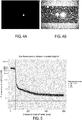
- a fluorescence image of an isolated bright microparticle surrounded by dark microparticles is illustrated in figure 4A.
- Figure 4B illustrates the same image with a post-processing over-exposition to show the COOH microparticles.
- a second step in order to measure the influence on pixels at a distance from the center of the bright microparticle, all the pixels corresponding to the dark microparticles at a distance between d and d + p (where p is a predefined step, e.g. equal to 1), are pooled together in a bin and their mean fluorescence and mean distance to the center of the bright microparticles are computed. The pixels of the dark microparticles are selected with the bright field image.
- the computed mean fluorescence is plotted over the computed mean distance.
- Each point on the plot corresponds to the average fluorescence of pixels at a given distance from one isolated bright microparticle.
- the plateau on the right of the x-axis corresponds to the bright microparticle whose radius is shown by the black vertical line.
- the fluorescence after said line thus corresponds to a halo of fluorescence surrounding the bright microparticle, which halo has a fluorescence decay profile.
- the relative fluorescence is computed by dividing the bin's means fluorescence by the fluorescence of the bright microparticle.
- Figure 6 illustrates the relative fluorescence decay profiles corresponding to the one of figure 5 .
- the values on the Y-axis of figure 6 can be interpreted as the proportion of the fluorescence of the bright microparticle that cross-talks at a given distance from the center of the bright microparticle.
- a chosen model is fitted to the relative fluorescence decay profile. More particularly, the sum of exponentials of relation (7) is chosen as the model, and in particular a sum of three exponentials.
- This model while flexible, still provides an analytical expression between the relative crosstalk fluorescence and the distance from center of the bright microparticle.
- the profile of relative fluorescence decay has a complicated shape that may be hard to fit with a sum of three exponentials (plateau from 0 to ⁇ 50 pixels then sharp slope up to 85). Therefore, in order to increase the goodness of fit of the model, the data of the sharp slope are discarded. This is justified by the fact that distance corresponding to the sharp slope won't be filled with any other microparticles.
- the radius of microparticle is approximatively of 56 pixels and therefore, the minimum distance between two microparticles is not expected to be smaller than 85 pixels.
- Figure 7 shows a detail of the relative fluorescence decay of figure 6 with the red line corresponding to the fitted model. Obviously, any suitable model may be used.
- Example of the cross-talk effect correction is illustrated in relation with figures 8 to 12 .
- This example corresponds to a bi-plex assay, and thus two types of microparticles or populations, with a first population of microparticles (biotin-RPE microparticles) being very bright compared to a second population of microparticles (COOH microparticles).
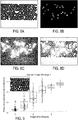
- a bright field image of a channel receiving the two populations is illustrated in figure 8A .
- the population fluorescence of the bright microparticles equals 112 A.U. (" Arbitrary Unit" ).
- biotin-RPE microparticles are sharp, with no halo of light surrounding them, so that it is difficult to figure out cross-talk phenomenon takes place.
- the contrast of the fluorescence image 8B at its maximum e.g. considering that image are coded on 8 bits, every pixels with original fluorescence greater or equal to is set value 255 and the pixels originally at 0 stay at 0
- the crosstalk effect becomes apparent ( figure 8C ).
- figure 8A and figure 8C figure 4D
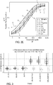
- Figure 9 illustrates the aggregate fluorescence ⁇ COOH pop of the COOH population computed based on the measured fluorescences ⁇ COOH meas of COOH microparticles belonging to a circle of 250 pixel radius, as illustrated in the upper left part of figure 9 .
- Aggregate fluorescence ⁇ COOH pop is here illustrated in function of the number of biotin-RPE microparticles in the circle.
- the fluorescence ⁇ COOH pop of the COOH population is positively correlated with the number of biotin-RPE microparticles, which illustrates the cross-talk phenomenon.
- cross-talk effect results in an increasing of the ⁇ COOH pop value as it is illustrated by the horizontal dashed line which corresponds to the population fluorescence of COOH microparticles in a monoplex assay under the same acquisition conditions (0.07A.U.).
- the population fluorescence ⁇ COOH pop of COOH population equals 0.44 A.U. i.e. a six fold increase of the monoplex value.
- This dependence of population fluorescence to the fluorescence of the other populations in a multiplex is detrimental to the assay precision and might notably induce false positive results.
- Figure 10 illustrates the extrapolation of a six fold increase of fluorescence on a IFN-g experiment and its impact on the estimated concentration using the calibration curve used to transform population fluorescence ⁇ COOH pop into INF-g concentration.
- the fluorescence measured on COOH microparticles should not be impacted by the fluorescence of bright microparticles present in the same field of view.
- the population fluorescence of COOH microparticles in multiplex assays is compared to a reference value.
- the reference value is the corresponding population fluorescence of COOH measured in a monoplex assay under the same experimental condition.
- the ratio p should be equal to one. In case of crosstalk between fluorescent and COOH microparticles, the ratio is expected to be greater than. Ratios p have to be computed before and after decrosstalk in order assess the improvement of signal robustness to the plex level induced by the cross-talk effect correction.
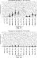
- Figures 11 and 12 illustrate fluorescence measured on the COOH microparticles respectively before and after the cross-talk effect correction.
- the labels on the x-axis contain the information of the approximate percentage of bright microparticle in the channel and the code type of bright microparticles present in the biplex (276 for 100% biotin-RPE coupled microparticles and 436 for 500% biotin-RPE coupled microparticles).
Landscapes
- Health & Medical Sciences (AREA)
- Chemical & Material Sciences (AREA)
- General Health & Medical Sciences (AREA)
- Immunology (AREA)
- Physics & Mathematics (AREA)
- Analytical Chemistry (AREA)
- General Physics & Mathematics (AREA)
- Biochemistry (AREA)
- Life Sciences & Earth Sciences (AREA)
- Nuclear Medicine, Radiotherapy & Molecular Imaging (AREA)
- Pathology (AREA)
- Chemical Kinetics & Catalysis (AREA)
- Dispersion Chemistry (AREA)
- Hematology (AREA)
- Clinical Laboratory Science (AREA)
- Optics & Photonics (AREA)
- Investigating, Analyzing Materials By Fluorescence Or Luminescence (AREA)
Priority Applications (8)
| Application Number | Priority Date | Filing Date | Title |
|---|---|---|---|
| EP15186210.9A EP3147650A1 (de) | 2015-09-22 | 2015-09-22 | Nebensprechkorrektur in mulitplex-analyse einer biologischen probe |
| BE2015/5687A BE1025903B1 (nl) | 2015-09-22 | 2015-10-26 | Overspraakcorrectie bij multiplexing-analyse van biologisch monster |
| US15/754,005 US10527549B2 (en) | 2015-09-22 | 2016-09-21 | Cross-talk correction in multiplexing analysis of biological sample |
| CN201680050974.8A CN108139325A (zh) | 2015-09-22 | 2016-09-21 | 生物样本的多路复用分析中的串扰校正 |
| PCT/EP2016/072341 WO2017050788A1 (en) | 2015-09-22 | 2016-09-21 | Cross-talk correction in multiplexing analysis of biological sample |
| EP16767297.1A EP3353532A1 (de) | 2015-09-22 | 2016-09-21 | Nebensprechkorrektur in mulitplexing-analyse einer biologischen probe |
| JP2018510106A JP2018529947A (ja) | 2015-09-22 | 2016-09-21 | 生物学的試料の多重分析におけるクロストークの修正 |
| AU2016328559A AU2016328559A1 (en) | 2015-09-22 | 2016-09-21 | Cross-talk correction in multiplexing analysis of biological sample |
Applications Claiming Priority (1)
| Application Number | Priority Date | Filing Date | Title |
|---|---|---|---|
| EP15186210.9A EP3147650A1 (de) | 2015-09-22 | 2015-09-22 | Nebensprechkorrektur in mulitplex-analyse einer biologischen probe |
Publications (1)
| Publication Number | Publication Date |
|---|---|
| EP3147650A1 true EP3147650A1 (de) | 2017-03-29 |
Family
ID=54185882
Family Applications (2)
| Application Number | Title | Priority Date | Filing Date |
|---|---|---|---|
| EP15186210.9A Withdrawn EP3147650A1 (de) | 2015-09-22 | 2015-09-22 | Nebensprechkorrektur in mulitplex-analyse einer biologischen probe |
| EP16767297.1A Withdrawn EP3353532A1 (de) | 2015-09-22 | 2016-09-21 | Nebensprechkorrektur in mulitplexing-analyse einer biologischen probe |
Family Applications After (1)
| Application Number | Title | Priority Date | Filing Date |
|---|---|---|---|
| EP16767297.1A Withdrawn EP3353532A1 (de) | 2015-09-22 | 2016-09-21 | Nebensprechkorrektur in mulitplexing-analyse einer biologischen probe |
Country Status (7)
| Country | Link |
|---|---|
| US (1) | US10527549B2 (de) |
| EP (2) | EP3147650A1 (de) |
| JP (1) | JP2018529947A (de) |
| CN (1) | CN108139325A (de) |
| AU (1) | AU2016328559A1 (de) |
| BE (1) | BE1025903B1 (de) |
| WO (1) | WO2017050788A1 (de) |
Families Citing this family (17)
| Publication number | Priority date | Publication date | Assignee | Title |
|---|---|---|---|---|
| EP3764096A4 (de) * | 2018-03-07 | 2021-04-28 | Konica Minolta, Inc. | Bildverarbeitungsverfahren, bildverarbeitungsvorrichtung und programm |
| CN109859188B (zh) * | 2019-01-31 | 2021-04-06 | 领航基因科技(杭州)有限公司 | 一种基于均值漂移算法的荧光串扰校正方法及其应用 |
| US11783917B2 (en) | 2019-03-21 | 2023-10-10 | Illumina, Inc. | Artificial intelligence-based base calling |
| US11210554B2 (en) | 2019-03-21 | 2021-12-28 | Illumina, Inc. | Artificial intelligence-based generation of sequencing metadata |
| US11423306B2 (en) * | 2019-05-16 | 2022-08-23 | Illumina, Inc. | Systems and devices for characterization and performance analysis of pixel-based sequencing |
| US11593649B2 (en) | 2019-05-16 | 2023-02-28 | Illumina, Inc. | Base calling using convolutions |
| CN119310167A (zh) | 2019-05-22 | 2025-01-14 | 株式会社日立高新技术 | 分析装置以及分析方法 |
| US12592298B2 (en) | 2020-02-20 | 2026-03-31 | Illumina, Inc. | Hardware execution and acceleration of artificial intelligence-based base caller |
| CN121034400A (zh) | 2020-02-20 | 2025-11-28 | 因美纳有限公司 | 基于人工智能的多对多碱基判读 |
| US12354008B2 (en) | 2020-02-20 | 2025-07-08 | Illumina, Inc. | Knowledge distillation and gradient pruning-based compression of artificial intelligence-based base caller |
| US12591780B2 (en) | 2020-02-20 | 2026-03-31 | Illumina, Inc. | Data compression for artificial intelligence-based base calling |
| US12525320B2 (en) | 2021-03-16 | 2026-01-13 | Illumina, Inc. | Neural network parameter quantization for base calling |
| US12217829B2 (en) | 2021-04-15 | 2025-02-04 | Illumina, Inc. | Artificial intelligence-based analysis of protein three-dimensional (3D) structures |
| US12444482B2 (en) | 2021-04-15 | 2025-10-14 | Illumina, Inc. | Multi-channel protein voxelization to predict variant pathogenicity using deep convolutional neural networks |
| US12530882B2 (en) | 2021-07-01 | 2026-01-20 | Illumina, Inc. | Efficient artificial intelligence-based base calling of index sequences |
| CN114527105B (zh) * | 2022-02-23 | 2025-08-22 | 上海交通大学 | 一种定量分析多种荧光物质成分的高精度通用方法 |
| CN114755164A (zh) * | 2022-03-09 | 2022-07-15 | 青岛瑞斯凯尔生物科技有限公司 | 一种用于细胞定量分析的荧光补偿方法及其系统 |
Citations (3)
| Publication number | Priority date | Publication date | Assignee | Title |
|---|---|---|---|---|
| WO2006015251A2 (en) * | 2004-07-29 | 2006-02-09 | The Research Foundation Of State University Of New York | System and method for cross-talk cancellation in a multilane fluorescence detector |
| US20110306506A1 (en) * | 2008-12-23 | 2011-12-15 | Biocartis Sa | Assay device and method for performing biological assays |
| US20120015825A1 (en) * | 2010-07-06 | 2012-01-19 | Pacific Biosciences Of California, Inc. | Analytical systems and methods with software mask |
Family Cites Families (5)
| Publication number | Priority date | Publication date | Assignee | Title |
|---|---|---|---|---|
| US20080241843A1 (en) * | 2006-12-21 | 2008-10-02 | Stanford University | Single-cell analysis systems, methods of counting molecules in a single-cell, cylindrical fluorescence detection systems |
| JP2011501189A (ja) * | 2007-10-25 | 2011-01-06 | ザ・リサーチ・ファウンデーション・オブ・ステイト・ユニバーシティー・オブ・ニューヨーク | 単一光子分光計 |
| RU2434288C1 (ru) * | 2010-06-08 | 2011-11-20 | Закрытое Акционерное Общество "Импульс" | Способ коррекции цифровых изображений |
| EP2484447A1 (de) * | 2011-02-07 | 2012-08-08 | Biocartis SA | Verbesserte codierte Mikroträger, Assay-System damit und Verfahren zur Assay-Durchführung |
| WO2012154734A1 (en) * | 2011-05-09 | 2012-11-15 | Rotman M Boris | System for detecting and enumerating biological particles |
-
2015
- 2015-09-22 EP EP15186210.9A patent/EP3147650A1/de not_active Withdrawn
- 2015-10-26 BE BE2015/5687A patent/BE1025903B1/nl not_active IP Right Cessation
-
2016
- 2016-09-21 EP EP16767297.1A patent/EP3353532A1/de not_active Withdrawn
- 2016-09-21 US US15/754,005 patent/US10527549B2/en not_active Expired - Fee Related
- 2016-09-21 AU AU2016328559A patent/AU2016328559A1/en not_active Abandoned
- 2016-09-21 CN CN201680050974.8A patent/CN108139325A/zh active Pending
- 2016-09-21 JP JP2018510106A patent/JP2018529947A/ja active Pending
- 2016-09-21 WO PCT/EP2016/072341 patent/WO2017050788A1/en not_active Ceased
Patent Citations (3)
| Publication number | Priority date | Publication date | Assignee | Title |
|---|---|---|---|---|
| WO2006015251A2 (en) * | 2004-07-29 | 2006-02-09 | The Research Foundation Of State University Of New York | System and method for cross-talk cancellation in a multilane fluorescence detector |
| US20110306506A1 (en) * | 2008-12-23 | 2011-12-15 | Biocartis Sa | Assay device and method for performing biological assays |
| US20120015825A1 (en) * | 2010-07-06 | 2012-01-19 | Pacific Biosciences Of California, Inc. | Analytical systems and methods with software mask |
Non-Patent Citations (5)
| Title |
|---|
| DIDIER FALCONNET ET AL: "Rapid, Sensitive and Real-Time Multiplexing Platform for the Analysis of Protein and Nucleic-Acid Biomarkers", ANALYTICAL CHEMISTRY, vol. 87, no. 3, 7 January 2015 (2015-01-07), US, pages 1582 - 1589, XP055254544, ISSN: 0003-2700, DOI: 10.1021/ac502741c * |
| DIDIER FALCONNET: "Rapid, Sensitive and Real-Time Multiplexing Platform for the Analysis of Protein and Nucleic-Acid Biomarkers", ANAL. CHEM., vol. 87, 2015, pages 1582 - 1589, XP055254544, DOI: doi:10.1021/ac502741c |
| NIELSEN T ET AL: "High efficiency beam splitter for multifocal multiphoton microscopy", JOURNAL OF MICROSCOPY, BLACKWELL SCIENCE, GB, vol. 201, March 2001 (2001-03-01), pages 368 - 376, XP009162871, ISSN: 0022-2720, [retrieved on 20011221], DOI: 10.1046/J.1365-2818.2001.00852.X * |
| PREGIBON DANIEL C ET AL: "Multifunctional encoded particles for high-throughput biomolecule analysis", SCIENCE, AMERICAN ASSOCIATION FOR THE ADVANCEMENT OF SCIENCE, US, vol. 315, no. 5817, 9 March 2007 (2007-03-09), pages 1393 - 1396, XP009105479, ISSN: 1095-9203, DOI: 10.1126/SCIENCE.1134929 * |
| RUDI IRAWAN ET AL: "Cross-Talk Problem on a Fluorescence Multi-Channel Microfluidic Chip System", BIOMEDICAL MICRODEVICES, KLUWER ACADEMIC PUBLISHERS, BO, vol. 7, no. 3, September 2005 (2005-09-01), pages 205 - 211, XP019205105, ISSN: 1572-8781, DOI: 10.1007/S10544-005-3027-4 * |
Also Published As
| Publication number | Publication date |
|---|---|
| BE1025903B1 (nl) | 2019-08-12 |
| EP3353532A1 (de) | 2018-08-01 |
| WO2017050788A1 (en) | 2017-03-30 |
| JP2018529947A (ja) | 2018-10-11 |
| US20180275059A1 (en) | 2018-09-27 |
| AU2016328559A1 (en) | 2018-03-01 |
| US10527549B2 (en) | 2020-01-07 |
| BE1025903A1 (nl) | 2019-08-06 |
| CN108139325A (zh) | 2018-06-08 |
Similar Documents
| Publication | Publication Date | Title |
|---|---|---|
| US10527549B2 (en) | Cross-talk correction in multiplexing analysis of biological sample | |
| EP3969884B1 (de) | Systeme und verfahren zur charakterisierung und erfolgsanalyse von pixel-basierter sequenzierung | |
| Rivnak et al. | A fully-automated, six-plex single molecule immunoassay for measuring cytokines in blood | |
| EP2861986B1 (de) | Verfahren zur quantifizierung von immunzellen in tumorgewebe und dessen anwendungen | |
| WO2020232409A1 (en) | Systems and devices for characterization and performance analysis of pixel-based sequencing | |
| JP2012514184A (ja) | 多重分析物の検出及び定量化のための方法 | |
| EP2588835B1 (de) | Vorrichtung, system und verfahren zur erhöhung der messgenauigkeit in einer partikelabbildungsvorrichtung | |
| JP2016045200A (ja) | 用紙ベースのセンサのロバストな比色分析処理方法 | |
| CA2684636A1 (en) | Multiplex microarrays and methods for the quantification of analytes | |
| WO2012012168A2 (en) | Apparatus, system, and method for increasing measurement accuracy in a particle imaging device using light distribution | |
| US11668711B2 (en) | Multiplexed diagnostic assay for iron and vitamin A deficiency and methods of use thereof | |
| CN101542269A (zh) | 生物测定中分子的多元检测 | |
| US8975087B2 (en) | Longitudinal assay | |
| CN119880859B (zh) | 使用检测微球测定样品中目标分子浓度的方法、计算机可读介质和分析设备 | |
| EP4078168B1 (de) | Verfahren zur kalibrierung von mindestens einer analytischen vorrichtung mit mehreren wiederholten hardware-komponenten | |
| JP4302924B2 (ja) | Dnaマイクロアレイのデータを統計的に分析する際の画像測定法 | |
| WO2007079094A2 (en) | Image acquisition, processing, and display | |
| US20230288331A1 (en) | Methods and related aspects for molecular tracking and analysis | |
| JP2023107419A (ja) | 定量方法、定量装置および定量プログラム | |
| US20040019433A1 (en) | Method for locating areas of interest of a substrate | |
| JP2009156715A (ja) | 生体物質検出装置 | |
| EP1010764A2 (de) | Hybridisierungsnachweisverfahren unter Verwendung von Biochips | |
| US20250034629A1 (en) | Method for Dynamic Range Expansion for Multiplex Assays | |
| WO2013033060A1 (en) | Devices having a calibration control region, systems and methods for immunohistochemical analyses | |
| US20060014301A1 (en) | Antibody-based system for detection of differential protein expression patterns |
Legal Events
| Date | Code | Title | Description |
|---|---|---|---|
| PUAI | Public reference made under article 153(3) epc to a published international application that has entered the european phase |
Free format text: ORIGINAL CODE: 0009012 |
|
| STAA | Information on the status of an ep patent application or granted ep patent |
Free format text: STATUS: THE APPLICATION HAS BEEN PUBLISHED |
|
| AK | Designated contracting states |
Kind code of ref document: A1 Designated state(s): AL AT BE BG CH CY CZ DE DK EE ES FI FR GB GR HR HU IE IS IT LI LT LU LV MC MK MT NL NO PL PT RO RS SE SI SK SM TR |
|
| AX | Request for extension of the european patent |
Extension state: BA ME |
|
| STAA | Information on the status of an ep patent application or granted ep patent |
Free format text: STATUS: THE APPLICATION IS DEEMED TO BE WITHDRAWN |
|
| 18D | Application deemed to be withdrawn |
Effective date: 20170930 |