EP3147718A1 - Appareil de développement et appareil de formation d'image doté de celui-ci - Google Patents
Appareil de développement et appareil de formation d'image doté de celui-ci Download PDFInfo
- Publication number
- EP3147718A1 EP3147718A1 EP15822643.1A EP15822643A EP3147718A1 EP 3147718 A1 EP3147718 A1 EP 3147718A1 EP 15822643 A EP15822643 A EP 15822643A EP 3147718 A1 EP3147718 A1 EP 3147718A1
- Authority
- EP
- European Patent Office
- Prior art keywords
- developer
- mixing member
- ribs
- developing
- shaft
- Prior art date
- Legal status (The legal status is an assumption and is not a legal conclusion. Google has not performed a legal analysis and makes no representation as to the accuracy of the status listed.)
- Granted
Links
- 238000011144 upstream manufacturing Methods 0.000 claims description 7
- 238000009751 slip forming Methods 0.000 claims description 2
- 230000001105 regulatory effect Effects 0.000 description 21
- 230000000694 effects Effects 0.000 description 12
- 230000003247 decreasing effect Effects 0.000 description 7
- 238000002474 experimental method Methods 0.000 description 6
- 238000005192 partition Methods 0.000 description 4
- 238000012546 transfer Methods 0.000 description 4
- 230000007547 defect Effects 0.000 description 3
- 239000000463 material Substances 0.000 description 3
- 238000010276 construction Methods 0.000 description 2
- 230000007423 decrease Effects 0.000 description 2
- 238000011161 development Methods 0.000 description 2
- 238000007599 discharging Methods 0.000 description 2
- 239000002184 metal Substances 0.000 description 2
- 229910052751 metal Inorganic materials 0.000 description 2
- 238000005086 pumping Methods 0.000 description 2
- XEEYBQQBJWHFJM-UHFFFAOYSA-N Iron Chemical compound [Fe] XEEYBQQBJWHFJM-UHFFFAOYSA-N 0.000 description 1
- 239000000696 magnetic material Substances 0.000 description 1
- 238000000034 method Methods 0.000 description 1
- 239000000203 mixture Substances 0.000 description 1
- 238000012545 processing Methods 0.000 description 1
- 238000006467 substitution reaction Methods 0.000 description 1
- 239000002699 waste material Substances 0.000 description 1
Images





Classifications
-
- G—PHYSICS
- G03—PHOTOGRAPHY; CINEMATOGRAPHY; ANALOGOUS TECHNIQUES USING WAVES OTHER THAN OPTICAL WAVES; ELECTROGRAPHY; HOLOGRAPHY
- G03G—ELECTROGRAPHY; ELECTROPHOTOGRAPHY; MAGNETOGRAPHY
- G03G15/00—Apparatus for electrographic processes using a charge pattern
- G03G15/06—Apparatus for electrographic processes using a charge pattern for developing
- G03G15/08—Apparatus for electrographic processes using a charge pattern for developing using a solid developer, e.g. powder developer
- G03G15/0822—Arrangements for preparing, mixing, supplying or dispensing developer
- G03G15/0887—Arrangements for conveying and conditioning developer in the developing unit, e.g. agitating, removing impurities or humidity
- G03G15/0891—Arrangements for conveying and conditioning developer in the developing unit, e.g. agitating, removing impurities or humidity for conveying or circulating developer, e.g. augers
- G03G15/0893—Arrangements for conveying and conditioning developer in the developing unit, e.g. agitating, removing impurities or humidity for conveying or circulating developer, e.g. augers in a closed loop within the sump of the developing device
-
- G—PHYSICS
- G03—PHOTOGRAPHY; CINEMATOGRAPHY; ANALOGOUS TECHNIQUES USING WAVES OTHER THAN OPTICAL WAVES; ELECTROGRAPHY; HOLOGRAPHY
- G03G—ELECTROGRAPHY; ELECTROPHOTOGRAPHY; MAGNETOGRAPHY
- G03G15/00—Apparatus for electrographic processes using a charge pattern
- G03G15/06—Apparatus for electrographic processes using a charge pattern for developing
- G03G15/08—Apparatus for electrographic processes using a charge pattern for developing using a solid developer, e.g. powder developer
- G03G15/0822—Arrangements for preparing, mixing, supplying or dispensing developer
- G03G15/0887—Arrangements for conveying and conditioning developer in the developing unit, e.g. agitating, removing impurities or humidity
- G03G15/0891—Arrangements for conveying and conditioning developer in the developing unit, e.g. agitating, removing impurities or humidity for conveying or circulating developer, e.g. augers
-
- G—PHYSICS
- G03—PHOTOGRAPHY; CINEMATOGRAPHY; ANALOGOUS TECHNIQUES USING WAVES OTHER THAN OPTICAL WAVES; ELECTROGRAPHY; HOLOGRAPHY
- G03G—ELECTROGRAPHY; ELECTROPHOTOGRAPHY; MAGNETOGRAPHY
- G03G15/00—Apparatus for electrographic processes using a charge pattern
-
- G—PHYSICS
- G03—PHOTOGRAPHY; CINEMATOGRAPHY; ANALOGOUS TECHNIQUES USING WAVES OTHER THAN OPTICAL WAVES; ELECTROGRAPHY; HOLOGRAPHY
- G03G—ELECTROGRAPHY; ELECTROPHOTOGRAPHY; MAGNETOGRAPHY
- G03G15/00—Apparatus for electrographic processes using a charge pattern
- G03G15/06—Apparatus for electrographic processes using a charge pattern for developing
-
- G—PHYSICS
- G03—PHOTOGRAPHY; CINEMATOGRAPHY; ANALOGOUS TECHNIQUES USING WAVES OTHER THAN OPTICAL WAVES; ELECTROGRAPHY; HOLOGRAPHY
- G03G—ELECTROGRAPHY; ELECTROPHOTOGRAPHY; MAGNETOGRAPHY
- G03G15/00—Apparatus for electrographic processes using a charge pattern
- G03G15/06—Apparatus for electrographic processes using a charge pattern for developing
- G03G15/08—Apparatus for electrographic processes using a charge pattern for developing using a solid developer, e.g. powder developer
- G03G15/0822—Arrangements for preparing, mixing, supplying or dispensing developer
- G03G15/0865—Arrangements for supplying new developer
-
- G—PHYSICS
- G03—PHOTOGRAPHY; CINEMATOGRAPHY; ANALOGOUS TECHNIQUES USING WAVES OTHER THAN OPTICAL WAVES; ELECTROGRAPHY; HOLOGRAPHY
- G03G—ELECTROGRAPHY; ELECTROPHOTOGRAPHY; MAGNETOGRAPHY
- G03G15/00—Apparatus for electrographic processes using a charge pattern
- G03G15/06—Apparatus for electrographic processes using a charge pattern for developing
- G03G15/08—Apparatus for electrographic processes using a charge pattern for developing using a solid developer, e.g. powder developer
- G03G15/095—Removing excess solid developer, e.g. fog preventing
-
- G—PHYSICS
- G03—PHOTOGRAPHY; CINEMATOGRAPHY; ANALOGOUS TECHNIQUES USING WAVES OTHER THAN OPTICAL WAVES; ELECTROGRAPHY; HOLOGRAPHY
- G03G—ELECTROGRAPHY; ELECTROPHOTOGRAPHY; MAGNETOGRAPHY
- G03G15/00—Apparatus for electrographic processes using a charge pattern
- G03G15/06—Apparatus for electrographic processes using a charge pattern for developing
- G03G15/08—Apparatus for electrographic processes using a charge pattern for developing using a solid developer, e.g. powder developer
- G03G15/09—Apparatus for electrographic processes using a charge pattern for developing using a solid developer, e.g. powder developer using magnetic brush
- G03G15/0921—Details concerning the magnetic brush roller structure, e.g. magnet configuration
-
- G—PHYSICS
- G03—PHOTOGRAPHY; CINEMATOGRAPHY; ANALOGOUS TECHNIQUES USING WAVES OTHER THAN OPTICAL WAVES; ELECTROGRAPHY; HOLOGRAPHY
- G03G—ELECTROGRAPHY; ELECTROPHOTOGRAPHY; MAGNETOGRAPHY
- G03G2215/00—Apparatus for electrophotographic processes
- G03G2215/08—Details of powder developing device not concerning the development directly
- G03G2215/0802—Arrangements for agitating or circulating developer material
- G03G2215/0816—Agitator type
- G03G2215/0819—Agitator type two or more agitators
-
- G—PHYSICS
- G03—PHOTOGRAPHY; CINEMATOGRAPHY; ANALOGOUS TECHNIQUES USING WAVES OTHER THAN OPTICAL WAVES; ELECTROGRAPHY; HOLOGRAPHY
- G03G—ELECTROGRAPHY; ELECTROPHOTOGRAPHY; MAGNETOGRAPHY
- G03G2215/00—Apparatus for electrophotographic processes
- G03G2215/08—Details of powder developing device not concerning the development directly
- G03G2215/0802—Arrangements for agitating or circulating developer material
- G03G2215/0816—Agitator type
- G03G2215/0827—Augers
Definitions
- the present invention relates to a developing apparatus for an image forming apparatus. More particularly, the present invention relates to a developing apparatus for an image forming apparatus using two-component developer consisting of toner and carrier, and an image forming apparatus having the same.
- An electrophotographic image forming apparatus develops an electrostatic latent image formed on an image carrier using developer, and transfers the developed image onto a print medium, thereby forming a predetermined image on the print medium.
- Developing apparatuses using two-component developer including toner and carrier as the developer for developing the electrostatic latent image are used.
- Such a developing apparatus includes a first mixing member for mixing the developer and a second mixing member for supplying the developer to the image carrier.
- the developing apparatus is required so that the second mixing member stably supplies the developer to a developing roller. For this it is good that a height of the developer in a second developer area in which the second mixing member is disposed is maintained higher than a height of the developer in a first developer area in which the first mixing member is disposed.
- an image density deviation of a vertical direction called as auger mark 110 is generated in a period of a pitch p of the second mixing member 100.
- the auto developer refill developing apparatus is mainly configured so that a developer discharge port is provided at an end portion of the mixing member, and when the height of the developer in the vicinity of the developer discharge port is above a certain value, the developer overflows to be discharged.
- the height of the developer is changed by the rotational speed of the mixing member.
- a printing speed may be lowered in accordance with printing conditions. For example, when printing a high-resolution image, or when printing a thick paper, the printing speed is lowered. At this time, the printing speed is often approximately half of the normal speed (maximum speed). Accordingly, the low-speed is generally referred to as a half speed.
- the rotational speed of the mixing member of the developing apparatus When the printing speed is changed as described above, the rotational speed of the mixing member of the developing apparatus also is changed according to the printing speed. At this time, the change in the height of the developer is very large. As fast as the rotational speed of the mixing member of the developing apparatus is, the height of the developer is increased so that a lot of developer is discharged. However, when the rotational speed of the mixing member is slow, the height of the developer is lowered so that the developer is not discharged. In other words, when the rotational speed of the mixing member is fast, the amount of developer decreases, and when the rotational speed of the mixing member is slow, the amount of developer increases.
- An aspect of the present disclosure relates to a developing apparatus that can maintain a height of developer in a second developer area including a second mixing member and a developing roller constant and can improve developer mixability of the second mixing member, and an image forming apparatus having the same.
- Another aspect of the present disclosure relates to a developing apparatus in which even when a printing speed is changed, change in an amount of developer is small, and image defects such as image density deviation, image density decrease and the like do not occur, and an image forming apparatus having the same.
- a developing apparatus for an image forming apparatus may include a developing roller; a developing housing which rotatably supports the developing roller and receives two-component developer; a first mixing member disposed in the developing housing to mix the developer; and a second mixing member disposed in the developing housing to be parallel to the first mixing member and adjacent to the developing roller, wherein the second mixing member may include a shaft, a spiral wing part formed along the shaft, and a plurality of ribs formed so as to protrude from a surface of the shaft.
- the plurality of ribs may be formed at predetermined intervals along an outer circumferential surface of the shaft.
- Each of the plurality of ribs may be continuously formed in a longitudinal direction of the shaft.
- the number of the plurality of ribs may satisfy a following formula. 4 ⁇ n ⁇ 8 wherein, n is the number of ribs.
- the surface of the shaft may be exposed between the plurality of ribs.
- the first mixing member may include a first shaft and a first spiral wing part formed along the first shaft, and each of the plurality of ribs may be formed to satisfy a following formula. Di 2 + h > Di 1
- Di1 is an inner diameter of the first mixing member
- Di2 is an inner diameter of the second mixing member
- h is a height of the plurality of ribs protruding from the shaft of the second mixing member.
- Each of the plurality of ribs may be formed to satisfy a following formula. 0.5 mm ⁇ h ⁇ Do 2 ⁇ Di 2 / 4 mm wherein, Do2 is an outer diameter of the second mixing member, Di2 is an inner diameter of the second mixing member, and h is a height of the plurality of ribs protruding from the shaft of the second mixing member.
- Each of the plurality of ribs may be formed to include an inclined plane, a height of the inclined plane of a downstream side based on a rotational direction of the second mixing member may be high, and a height of the inclined plane of a upstream side may be low.
- Each of the plurality of ribs may further include a vertical plane vertically expended from the surface of the shaft, and a connecting plane connecting the vertical plane and the inclined plane.
- the inclined plane of each of the plurality of ribs may include a concave groove or a convex protrusion.
- the inclined plane of each of the plurality of ribs may be formed in a concave curved line or a convex curved line.
- Each of the plurality of ribs may be formed to have a cross-section of any one shape of rectangle, triangle, and semicircle.
- the developing housing may be provided with a developer discharge port which is formed in a downstream of a developer conveying direction of the first mixing member and discharges excess developer outside the developing housing.
- the developing housing may be provided with a developer supply port which is formed in an upstream of the developer conveying direction of the first mixing member and supplies new developer to an inside of the developing housing.
- the developer may include toner and carrier.
- An image forming apparatus may include an image carrier on which an electrostatic latent image is formed; and a developing apparatus including one of the above-described features to supply developer to the image carrier.
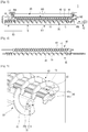
- Fig. 2 is a cross-sectional view illustrating a developing apparatus according to an embodiment of the present disclosure
- Fig. 3 is a front view illustrating a developing apparatus according to an embodiment of the present disclosure without a cover.
- Fig. 4 is a perspective view illustrating a first mixing member and a second mixing member of the developing apparatus of Fig. 3
- Fig. 5 is a sectional perspective view illustrating a first mixing member and a second mixing member of a developing apparatus according to an embodiment of the present disclosure.
- a developing apparatus 1 for an image forming apparatus may include a developing housing 10, a developing roller 20, a first mixing member 30, a second mixing member 40, and a upper cover 80.
- the developing housing 10 rotatably supports the developing roller 20, and includes a space to accommodate developer.
- the developer accommodating space includes a first developer area 11 in which the first mixing member 30 is rotatably disposed and a second developer area 12 in which the second mixing member 40 is rotatably disposed.
- the second developer area 12 is adjacent to the developing roller 20.
- a partition wall 15 exists between the first developer area 11 and the second developer area 12, and is formed in parallel to the first and second mixing members 30 and 40.
- the partition wall 15 is provided with two openings 16 and 17 that allows the developer in the first developer area 11 and the second developer area 12 to be circulated. Accordingly, when the first mixing member 30 and the second mixing member 40 rotate, as indicated by arrows M1, M2, M3, and M4 in Fig.
- the developer is circulated between the first developer area 11 and the second developer area 12 through the two openings 16 and 17 provided in the partition wall 15.
- the developer uses two-component developer including toner and carrier.
- the carrier is to carry the toner, and is formed from a magnetic material that can be attached to a magnet such as iron powder.
- the developing housing 10 is provided with a first regulating member 71 which faces the developing roller 20 and regulates a thickness of the developer layer attached to the developing roller 20.
- the first regulating member 71 may be a doctor blade.
- a second regulating member 72 is disposed between the partition wall 15 and the first regulating member 71 of the developing housing 10.
- the second regulating member 72 is located above the second mixing member 40, and regulates the amount of the developer attached to the developing roller 20, thereby dropping the developer over the second mixing member 40.
- a developer supply port 61 is provided adjacent to an end of the first developer area 11 of the developing housing 10, in detail, the end of the first mixing member 30 to the upstream side of the developer conveying direction (arrow M1) of the first mixing member 30.
- a developer discharge port 62 is provided adjacent to the other end of the first mixing member 30 to the downstream side thereof.
- the developer supply port 61 is connected to a developer supply unit 60 in which toner and a small amount of carrier are stored, thereby supplying the developer containing toner and carrier to the end of the first developer area 11. The toner is consumed by the development, but the added carrier becomes in excess, thereby being discharged to the outside of the developing housing 10 through the developer discharge port 62 provided in the other end of the first developer area 11.
- the developing housing 10 is provided with the developer supply port 61 and the developer discharge port 62.
- general developing apparatuses may not be provided with the developer supply port 61 and the developer discharge port 62.
- the developing roller 20 develops the electrostatic latent image formed on the image carrier 120 into a developer image by moving the developer in the second developer area 12 to the image carrier 120.
- the developing roller 20 includes a developing sleeve 21 and a magnet roller 22 disposed inside the developing sleeve 21.
- the developing sleeve 21 is formed in a hollow cylindrical shape, and is disposed to rotate about the developing housing 10.
- the magnet roller 22 is disposed concentrically with the developing sleeve 21, and is fixed to the developing housing 10 not to rotate.
- the magnet roller 22 is formed to include a plurality of magnetic poles S1, S3, S3, N1, and N2 so as to move the developer in the second developer area 12 to the image carrier 120.
- An example of arrangement of the plurality of magnetic poles S1, S3, S3, N1, and N2 configuring the magnet roller 22 is illustrated in Fig. 6 .
- the plurality of magnetic poles of the magnet roller 22 may include a catch pole S3, a regulating pole N2, a main pole S1, a conveying pole N1, and a separating pole S2.
- the catch pole S3 is located adjacent to the second mixing member 40, and renders the developer in the second developer area 12 to be attached onto the developing sleeve 21.
- the regulating pole N2 is formed of a magnet having a polarity opposite to the catch pole S3, is disposed adjacent to the first regulating member 71 at one side of the catch pole S3, and allows the developer attached to the developing sleeve 21 to pass by the first regulating member 71.
- the main pole S1 is formed of a magnet having the same polarity as the catch pole S3.
- the main pole S1 is disposed adjacent to the image carrier 120 at one side of the regulating pole N2, and causes the toner of the developer passing through the regulating pole N2 to be moved to the image carrier 120.
- the conveying pole N1 is formed of a magnet having a polarity opposite to the catch pole S3, is disposed at one side of the main pole S1, and causes the developer passing through a developing region 13 to be moved to the separating pole S2.
- the separating pole S2 is disposed at one side of the catch pole S3, and is formed of a magnet having the same polarity as the catch pole S3.
- the developer which is conveyed to the separating pole S2 by the conveying pole N1 is separated from the developing sleeve 21 by the repulsion of the catch pole S3 and the separating pole S2.
- the catch pole S3 is an S pole
- the catch pole may be formed as an N pole. At this time, polarities of the other poles are changed to correspond to the catch pole.
- the upper cover 80 is provided to cover the first mixing member 30, the second mixing member 40, and the developing roller 20 above the developing housing 10. At this time, the upper cover 80 covers a portion of the developing roller 20 so that another portion of the developing roller 20 is exposed to face the image carrier 120.
- the upper cover 80 may be provided with a developer supply unit 60 for supplying the developer to the developer supply port 61.
- the lower cover 90 is disposed below the developing housing 10, and may be provided with a waste toner receiving portion 91 for receiving the developer discharged through the developer discharge port 62.
- the first mixing member 30 is rotatably disposed in the first developer area 11 of the developing housing 10.
- the first mixing member 30 includes a first shaft 31 and a first wing part 33.
- the first shaft 31 is supported so that the first mixing member 30 rotates with respect to the developing housing 10.
- the first wing part 33 is formed in a spiral shape along the first shaft 31.
- the first wing part 33 may be formed in a form that a thin strip is disposed in a spiral shape on the outer circumferential surface of the first shaft 31. Accordingly, when the first mixing member 30 is rotated, the developer in the first developer area 11 is mixed and conveyed in the axial direction of the first mixing member 30.
- the first shaft 31 may be formed in a double shaft.
- an inner shaft 31a may be formed of a high strength metal
- an outer shaft 31b may be formed of a material such as plastic so that the outer shaft 31b may be molded integrally with the first wing part 33.
- the second mixing member 40 is rotatably disposed in the second developer area 12 of the developing housing 10.
- the second mixing member 40 is disposed parallel to the first mixing member 30 and adjacent to the developing roller 20 in the developing housing 10.
- the second mixing member 40 may include a second shaft 41, a second wing part 43, and a plurality of ribs 50.
- the second shaft 41 is supported so that the second mixing member 40 rotates with respect to the developing housing 10.
- the second wing part 43 is formed in a spiral shape along the second shaft 41.
- the second wing part 43 may be formed in a form that a thin strip is disposed in a spiral shape on the outer circumferential surface of the second shaft 41.
- an inner diameter Di2 and an outer diameter Do2 of the second mixing member 40 may be formed to be the same as the inner diameter Di2 and the outer diameter Do1 of the first mixing member 30.
- the inner diameter Di2 of the second mixing member 40 refers to an outer diameter of the second shaft 41
- the outer diameter Do2 of the second mixing member 40 refers to an outer diameter of the second wing part 43.
- the inner diameter Di1 of the first mixing member 30 refers to an outer diameter of the first shaft 31
- the outer diameter Do1 of the first mixing member 30 refers to an outer diameter of the first wing part 33.
- the second shaft 41 may be formed in a double shaft.
- an inner shaft 41a may be formed of a high strength material such as metal
- an outer shaft 41b may be formed of an easily molded material such as plastic so that the outer shaft 41b may be molded integrally with the second wing part 43 and the plurality of ribs 50.
- the plurality of ribs 50 are formed to protrude from the outer circumferential surface of the second shaft 41. Also, each of the plurality of ribs 50 may be formed parallel to the axial direction of the second shaft 41. Due to the plurality of ribs 50, the conveying speed of the developer by the second mixing member 40 is decreased, the mixability is improved, and the height H2 of developer in the second developer area 12 becomes higher than the height H1 of developer in the first developer area 11 in which the first mixing member 30 is disposed.
- the height H1 or H2 of developer refers to a height from a bottom surface of the first developer area 11 or the second developer area 12 to the top of the developer in the first developer area 11 or the second developer area 12.
- the volume of the developer accommodated in the first developer area 11 or the second developer area 12 changes in accordance with the change in the height H1 or H2 of the developer. In other words, if the height H1 and H2 of the developer is high, the volume of the developer occupying the developer areas 11 and 12 becomes large. If the height H1 and H2 of the developer is low, the volume of the developer occupying the developer area 11 and 12 becomes small.
- the inner diameter Di1 of the first mixing member 30, the inner diameter Di2 of the second mixing member 40, and the height h of the rib 50 may satisfy the following relationship. Di 1 ⁇ Di 2 + 2 h
- Di is the inner diameter of the first mixing member 30
- Di2 is the inner diameter of the second mixing member 40
- h is a height of the rib protruding from the second shaft 41 of the second mixing member 40.
- a unit of each of the Di1, Di2, and h is mm.
- the developer supply to the developing roller 20 is stabilized so that the amount of the developer regulated by the first regulating member 71 is stable, thereby obtaining a uniform image density.
- the number of the plurality of ribs 50 formed in the second mixing member 40 may be in a range of 4 to 8.
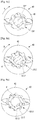
- Fig. 7a illustrates a case that the number of the ribs 50 is four
- Fig. 7b illustrates a case that the number of the ribs 50 is six
- Fig. 7c illustrates a case that the number of the ribs 50 is eight. If the number of the ribs 50 is less than four, difference in developer density between a portion in which there is bounce of the developer by the ribs 50 and a portion in which there is not the bounce of the developer by the ribs 50 becomes large so that image density deviation may easily occur. If the number of the ribs 50 is more than eight, a space between the rib 50 and the rib 50 is narrow so that the effect of the developer bounce by the ribs 50 is reduced.
- the height h of the rib 50 formed on the second mixing member 40 may satisfy the following condition. 0.5 mm ⁇ h ⁇ Do 2 ⁇ Di 2 / 4 mm
- Do2 is the outer diameter of the second mixing member 40
- Di2 is the inner diameter of the second mixing member 40
- h is the height of each of the plurality of ribs 50 protruding from the surface of the second shaft 41 of the second mixing member 40.
- the height h of the ribs 50 of the second mixing member 40 is in the range of 1mm to 2mm among the above-described conditions. If the height h of the rib 50 is less than 0.5 mm, the developer bounce effect by the ribs 50 is insufficient. If the height h of the rib 50 is over (the outer diameter of the second mixing member - the inner diameter of the second mixing member)/4, the developer bounce effect by the ribs 50 is increased so that a possibility that a rib mark occurs is increased.
- the rib mark refers to the image density deviation that is generated in the vertical direction with respect to an advancing direction of the print medium by the density difference of the developer between the portion in which there is the bounce of the developer by the ribs 50 and the portion in which there is not the bounce of the developer by the ribs 50.
- the plurality of ribs 50 of the second mixing member 40 as described above may be formed by a predetermined interval on the outer circumferential surface of the second shaft 41, and may extend in the longitudinal direction of the second shaft 41, respectively. Accordingly, as illustrated in Fig. 5 , the plurality of ribs 50 may be formed on the outer circumferential surface of the second shaft 41 between the second wing parts 43 in the longitudinal direction of the second shaft 41. Alternatively, the second wing part 43 may be formed on the second shaft 41 in the form that the second wing part 43 cuts the plurality of ribs 50 formed on the outer circumferential surface of the second shaft 41 in the longitudinal direction.
- the plurality of ribs 50 formed on the second mixing member 40 may be formed to have a variety of cross-sectional shapes.
- Figs. 7a, 7b , and 7c illustrate cases in which the cross-section of rib is a trapezoidal shape.
- one side of the rib 50 is formed in a vertical plane 52 that is extended substantially perpendicularly from the outer circumferential surface of the second shaft 41, and the other side of the rib 50 is formed in an inclined plane 51 that is inclined with respect to the outer circumferential surface of the second shaft 41.
- the inclined plane 51 is formed to be inclined upward toward the downstream side based on the rotational direction (arrow R direction) of the second mixing member 40.
- the inclined plane 51 is formed so that the height of the downstream side is higher than the height of the upstream side based on the rotational direction R of the second mixing member 40.
- a connecting plane 53 is formed between the vertical plane 52 and the inclined plane 51.
- the connecting plane 53 may be formed to be substantially perpendicular to the vertical plane 52.
- the vertical plane 52 of the rib 50 may be formed in an inclined plane having a greater slope than the above-described inclined plane 51. At this time, the inclined plane is inclined downward toward the downstream side of the rotational direction R of the second mixing member 40, as opposed to the inclination of the above-described inclined plane 51.
- the height H1 of the developer in the first developer area 11 is relatively increased, it is easy that the surplus developer is discharged through the developer discharge port 62.
- the amount of the developer is small, and at the half speed, the amount of the developer is increased.
- the plurality of ribs 50 are formed on the second mixing member 40, the amount of the developer is increased at the maximum speed, and the amount of the developer is reduced at the half speed so that the change in the developer amount at the maximum speed and at the half speed is reduced.
- Figs. 8a, 8b , 8c, and 8d are cross-sectional views illustrating various variations of the plurality of ribs illustrated in Fig. 7c .
- each of the plurality of ribs 50-1 as illustrated in Fig. 8a is different from the cross-section of each of the plurality of ribs 50 as illustrated in Fig. 7c in that there is no connecting plane 53.
- the cross-section of the rib is formed not to have the connecting plane 53 by intersecting the vertical plane 52 and the inclined plane 51 of the rib 50 as illustrated in Fig. 7c with each other, the cross-section of the rib 50-1 of Fig. 8a may be formed. Accordingly, the ribs 50-1 of Fig. 8a have a cross-section of saw-tooth shape.
- each of the plurality of ribs 50' and 50" as illustrated in Figs. 8b and 8c is different from the cross-section of each of the plurality of ribs 50 as illustrated in Fig. 7c in the shape of the inclined plane 51.
- the inclined plane 51' of rib 51' of Fig. 8b is formed in a concave curved surface
- the inclined plane 51" of rib 51" of Fig. 8c is formed in a convex curved surface.
- Figs. 8b and 8c show a case that the entire inclined plane 51'and 51" of the rib 50' and 50" is formed in a concave curved surface or in a convex curved surface.
- the inclined plane 51 of the rib 50 may be provided with a concave groove or a convex protrusion.
- each of the plurality of ribs 50-2 as illustrated in Fig. 8d is different from the cross-section of each of the plurality of ribs 50 as illustrated in Fig. 7c in that the inclination direction of the inclined plane 51 is opposed to. That the cross-section of each of the plurality of ribs 50-2 as illustrated in Fig. 8d has the vertical plane 52 and the connecting plane 53 is the same as the cross-section of each of the plurality of ribs 50 as illustrated in Fig. 7c .
- the inclined plane 51-2 is formed to be inclined downward toward the downstream side of the rotational direction R of the second mixing member 40.
- the plurality of ribs 50, 50-1, 50', 50", and 50-2 formed on the second mixing member 40 as illustrated in Figs. 7a to 8d are formed so that the outer surface of the second shaft 41 is not exposed.
- the plurality of ribs 50 are formed so that the lower end of the vertical plane 52 of one of the plurality of ribs 50 is connected to the lower end of the inclined plane 51 of the next rib 50. Accordingly, the outer surface of the second shaft 41 on which the plurality of ribs 50 are formed is not exposed.
- the plurality of ribs 50 may be formed so that the outer surface of the second shaft 41 is exposed between the pluralities of ribs 50.
- Figs. 9a , 9b, 9c, 9d , 9e , and 9f are cross-sectional views illustrating various examples of a plurality of ribs of a second mixing member 40 formed so that the outer surface of the second shaft 41 is exposed between the plurality of ribs.
- Fig. 9a shows a structure of the plurality of ribs 50-3 in that the cross-section of each of the plurality of ribs 50-3 is a trapezoidal shape similar to each of the plurality of ribs 50 as illustrated in Fig. 7c , and the lower end of the inclined plane 51-3 of the rib 50-3 is spaced apart from the lower end of the vertical plane 52-3 of an adjacent rib 50-3 so that the surface of the second shaft 41 is exposed.
- Fig. 9b shows a case in which the cross-section of each of the plurality of ribs 55 is a rectangular shape. Accordingly, there are spaces 56 in which the surface of the second shaft 41 are exposed between the pluralities of ribs 55 of the second mixing member 40.
- Fig. 9c shows a case in which the cross-section of each of the plurality of ribs 55' is an isosceles trapezoidal shape. Accordingly, there are spaces in which the surface of the second shaft 41 are exposed between the pluralities of ribs 55' of the second mixing member 40.
- Fig. 9d shows a case in which the ribs 55" are formed by performing a round processing with respect to edges of the plurality of ribs 55' having the cross-section of an isosceles trapezoid of Fig. 9c .
- the second mixing member 40 is provided with spaces in which the surface of the second shaft 41 is exposed.
- Fig. 9e shows a case in which the cross-section of each of the plurality of ribs 55-1 is a semicircle. Accordingly, the surface of the second shaft 41 is exposed in spaces between the pluralities of ribs 55-1 of the second mixing member 40.
- Fig. 9f shows a case in which the cross-section of each of the plurality of ribs 55-2 is a triangle. Accordingly, the surface of the second shaft 41 is exposed in spaces between the pluralities of ribs 55-2 of the second mixing member 40.
- the plurality of ribs 50 are formed continuously without interruption between the second wing part 43 in the axial direction of the second shaft 41 on the surface of the second shaft 41 of the second mixing member 40.
- the plurality of ribs 50 may be formed in the form broken in the axial direction of the second shaft 41.
- Fig. 10 shows a case in which the plurality of ribs 57 are formed in the form broken in the axial direction of the second shaft 41.
- Fig. 10 is a partial perspective view illustrating a portion of the second shaft 41 and the second wing part 43 of the second mixing member 40.
- the plurality of ribs 57 formed on the second mixing member 40 have a cross-section of a rectangular shape, and eight ribs 57 are formed on the surface of the second shaft 41 in the circumferential direction. Also, three lines of ribs 57-1, 57-2, and 57-3 formed in the longitudinal direction of the second shaft 41.
- the ribs 57-2 located at the middle are formed to be rotated a predetermined angle with respect to the ribs 57-1 and 57-3 located on both sides based on the central axis C of the second shaft 41.
- the ribs 57-2 located at the middle are formed to face the spaces of the ribs 57-1 and 57-3 located on both sides in which the second shaft 41 is exposed.
- Fig. 10 has been described the case in which the cross-sections of the plurality of ribs 57 are a rectangular; however, the structure of the ribs 57 as illustrated in Fig. 10 is not limited thereto. Also, the plurality of ribs having the cross-section as illustrated in Fig. 9a to 9f may be formed in the same structure as that of Fig. 10 .
- Fig. 11 is a cross-sectional view illustrating a flow of developer in a second developer area of a developing apparatus according to an embodiment of the present disclosure.
- the first mixing member 30 and the second mixing member 40 are rotated at the same speed. Since the second mixing member 40 includes the plurality of ribs 50, the conveying speed of the developer is lowered, and the mixability is enhanced. Accordingly, the height H2 of the developer in the second developer area 12 including the second mixing member 40 and the developing roller 20 becomes higher than the height H1 of the developer in the first developer area 11 including the first mixing member 30.
- the developer When the second mixing member 40 is rotated, the developer is moved from the second mixing member 40 to the catch pole S3 of the developing roller 20.
- the developer moved to the catch pole S3 is attached to the developing roller 20, and is moved to the regulating pole N2 by the rotation of the developing roller 20. While moving to the regulating pole N2, some of the developer is removed from the developing roller 20 by the second regulating member 72, is returned to the second mixing member 40, and is mixed again.
- the developer attached to the developing roller 20 passes by the first regulating member 71, and is moved to the image developing region 13 in which the main pole S1 is located. In the image developing region 13, toner of the developer is moved to the image carrier 120 so as to develop the electrostatic latent image formed on the image carrier 120.
- the developer having passed through the image developing region 13 passes by the conveying pole N1, and then is moved to the separating pole S2.
- the developer moved to the separating pole S2 is separated and dropped from the developing roller 20 by repulsion with the catch pole S3 having the same polarity as the separating pole S2.
- the dropped developer is mixed again by the second mixing member 40.
- the height H2 of the developer in the second developer area 12 in which the second mixing member 40 and the developing roller 20 are disposed may be increased so that the developer supply to the developing roller 20 may be stabilized to form an image with a uniform concentration. Accordingly, image defects such as auger mark that occurs when the height H2 of the developer in the second developer area 12 is low do not occur. Also, the mixability of the developer is improved in the second developer area 12 by the plurality of ribs 50 formed on the second mixing member 40 so that the charging amount of the developer may be stabilized. Accordingly, it is possible to prevent occurrence of toner scattering.
- the developer that is removed and dropped by the second regulating member 72 or the developer that is separated from the developing roller 20 by the separating pole S2 may be easily attached to the catch pole S3.
- the developer the toner concentration of which is decreased after developed in the image developing region 13 is separated and dropped in the separating pole S2, and is reattached to the catch pole S3 before being mixed by the second mixing member 40, the developer with the low toner concentration is circulated along the developing roller 20. In such a case, the concentration of the printed image is reduced.
- the height H2 of the developer in the second developer area 12 in which the second mixing member 40 is disposed constant is important to the developing apparatus 1, in particular, to the auto developer refill developing apparatus.
- the second mixing member 40 is provided with the plurality of ribs 50 as the developing apparatus 1 according to the present disclosure, the height H2 of the developer in the second developer area 12 may be kept more constant than the conventional developing apparatus.
- the plurality of ribs 50 of the second mixing member 40 was tested with respect to three types of cross-sectional shapes, that is, the rib 55 of a rectangular cross-section (A type) as illustrated in Fig. 9b , the rib 50 of a trapezoidal cross-section (B type) as illustrated in Fig. 7c , and the rib 50-2 of a trapezoidal cross-section (C type) having a slope opposite to the cross-section of Fig. 7c as illustrated in Fig. 8d .
- the cross-sectional areas of the ribs 55, 50, and 50-2 of all shapes are identical.
- the amount of developer of the developing apparatus 1 having the second mixing member 40 using the A type of ribs 55 is the lowest. This is considered to be because when the number of rotations of the second agitating member 40 is high, the developer between the rib 55 and the rib 55 is difficult to be replaced so that the developer bouncing effect is small. When the bouncing effect is small, the mixability of the developer is lowered, but the conveyability is increased. When the conveyability of the developer is increased, the height H2 of the developer in the second developer area 12 is lowered, but the height H1 of the developer in the first developer area 11 is relatively increased. Accordingly, because the discharge of the developer through the developer discharge port 62 becomes easy, the amount of the developer is reduced.
- the developing apparatus 1 having the second mixing member 40 using the C type of ribs 55-2 has a middle amount of developer.
- the amount of developer of the developing apparatus 1 having the second mixing member 40 using the C type of ribs 50-2 is the largest.
- the C type of rib 50-2 has a weak force for pumping the developer, but the C type of rib 50-2 has a force to push up the developer toward the developing roller 20.
- the amount of developer of the developing apparatus 1 having the second mixing member 40 using the A type of ribs 55 is the lowest. This is presumably because the A type of rib 55 can pump the developer in the rotational direction, but the pumping effect may be reduced due to the insufficient replacement of the developer between the rib and the rib. In this case, because the conveyability of the developer is increased than the mixability, the height H2 of developer in the second developer area 12 is decreased, and the height H1 of developer in the first developer area 11 is relatively increased so that the discharge of the developer through the developer discharge port 62 becomes easier.
- the developing apparatus 1 having the second mixing member 40 using the B type of ribs 50 has the amount of developer larger than the developing apparatus 1 using the A type of ribs 55.
- the ribs 50 having the B type of cross-section among the ribs 55, 50, and 50-2 having three types of cross-sections has the smallest difference in the amount of developer between the maximum speed and the half speed, that is, 4.4g.
- the change in the amount of developer of the developing apparatus 1 having the ribs 50 of the B type of cross-section is the smallest.
- the ribs may be formed in the B type of ribs 50 having an inclined plane 51 upwardly inclined towards the downstream side of the rotational direction of the second mixing member 40.
- Fig. 13 is a view schematically illustrating an image forming apparatus having a developing apparatus according to an embodiment of the present disclosure.
- parts that perform an operation for forming an image on a print medium are conceptually illustrated, and a print medium feeding unit, a print medium discharging unit, and the like that are included in the general image forming apparatus are omitted.
- the image forming apparatus 100 may include an exposure unit 110 for emitting light corresponding to predetermined printing data, an image carrier 120 on which an electrostatic latent image is formed by the light emitted from the exposure unit 110, a developing apparatus 1 for developing the electrostatic latent image formed on the image carrier 120 into a developer image, a transfer roller 130 for transferring the developer image formed on the image carrier 120 onto a print medium P, and a fusing unit 140 for fusing the transferred developer image on the print medium P.
- Structures and functions of the exposure unit 110, the image carrier 120, the transfer roller 130, and the fusing unit 140 are the same as or similar to those of the conventional image forming apparatus; therefore, detailed descriptions thereof are omitted.
- the developing apparatus 1 is the same as the developing apparatus 1 according to the above-described embodiment; therefore, a detailed description thereof is omitted.
- the exposure unit 110 emits light to form an electrostatic latent image corresponding to the printing data on the surface of the image carrier 120.
- the developing apparatus 1 causes developer in the second developer area 12 to be moved to the catch pole S3 of the developing roller 20 by rotating the first and second mixing members 30 and 40.
- the developer attached to the developing roller 20 is regulated by the first and second regulating members 71 and 72, and then is moved to the image developing region 13 that faces the image carrier 120.
- Toner is moved from the developer located at the image developing region 13 to the image carrier 120, thereby developing the electrostatic latent image into a developer image.
- the developer completing the development is dropped into the second developer area 12 by the separating pole S2 of the developing roller 20, and then is remixed by the second mixing member 40.
- the developer image formed on the image carrier 120 is transferred onto the print medium P by the transfer roller 130.
- the developer image transferred onto the print medium P is fused to the print medium P while passing through the fusing unit 140.
- the print medium P the fusing of which is completed is discharged to the outside of the image forming apparatus 100 by the print medium discharging unit, so the printing is completed.
Landscapes
- Physics & Mathematics (AREA)
- General Physics & Mathematics (AREA)
- Dry Development In Electrophotography (AREA)
Applications Claiming Priority (2)
| Application Number | Priority Date | Filing Date | Title |
|---|---|---|---|
| KR1020140088642A KR20160008429A (ko) | 2014-07-14 | 2014-07-14 | 현상장치 및 이를 구비한 화상형성장치 |
| PCT/KR2015/007284 WO2016010333A1 (fr) | 2014-07-14 | 2015-07-14 | Appareil de développement et appareil de formation d'image doté de celui-ci |
Publications (3)
| Publication Number | Publication Date |
|---|---|
| EP3147718A1 true EP3147718A1 (fr) | 2017-03-29 |
| EP3147718A4 EP3147718A4 (fr) | 2018-01-17 |
| EP3147718B1 EP3147718B1 (fr) | 2020-04-08 |
Family
ID=55078754
Family Applications (1)
| Application Number | Title | Priority Date | Filing Date |
|---|---|---|---|
| EP15822643.1A Active EP3147718B1 (fr) | 2014-07-14 | 2015-07-14 | Appareil de développement et appareil de formation d'image doté de celui-ci |
Country Status (4)
| Country | Link |
|---|---|
| US (1) | US10101687B2 (fr) |
| EP (1) | EP3147718B1 (fr) |
| KR (1) | KR20160008429A (fr) |
| WO (1) | WO2016010333A1 (fr) |
Families Citing this family (3)
| Publication number | Priority date | Publication date | Assignee | Title |
|---|---|---|---|---|
| JP2019028322A (ja) * | 2017-07-31 | 2019-02-21 | 株式会社リコー | 現像装置及びプロセスカートリッジ及び画像形成装置 |
| JP7367449B2 (ja) * | 2019-10-15 | 2023-10-24 | 京セラドキュメントソリューションズ株式会社 | 現像装置およびそれを備えた画像形成装置 |
| JP7476680B2 (ja) | 2020-06-10 | 2024-05-01 | コニカミノルタ株式会社 | 画像形成装置及び画像濃度不良の検出方法 |
Family Cites Families (14)
| Publication number | Priority date | Publication date | Assignee | Title |
|---|---|---|---|---|
| JPH0713420A (ja) * | 1993-06-22 | 1995-01-17 | Canon Inc | 現像装置 |
| JPH07244425A (ja) * | 1994-03-07 | 1995-09-19 | Ricoh Co Ltd | 2成分現像装置の剤撹拌混合装置 |
| JP3483322B2 (ja) * | 1994-11-04 | 2004-01-06 | 株式会社リコー | 現像装置 |
| KR980002426U (ko) | 1996-06-28 | 1998-03-30 | 축의 길이가 조절되는 자동차의 조향축 | |
| US6266504B1 (en) * | 2000-02-10 | 2001-07-24 | Toshiba Tec Kabushiki Kaisha | Developing apparatus and image forming apparatus |
| JP4755867B2 (ja) | 2004-11-26 | 2011-08-24 | 株式会社リコー | 現像装置、及びこれを備えたプロセスカートリッジ、画像形成装置 |
| JP2007101928A (ja) * | 2005-10-05 | 2007-04-19 | Fuji Xerox Co Ltd | 現像装置、画像形成装置及び現像剤搬送部材の製造方法 |
| JP4887762B2 (ja) * | 2005-12-01 | 2012-02-29 | 富士ゼロックス株式会社 | 現像装置及び画像形成装置 |
| JP4819547B2 (ja) * | 2006-03-29 | 2011-11-24 | キヤノン株式会社 | 現像装置 |
| KR20080018704A (ko) | 2006-08-25 | 2008-02-28 | 삼성전자주식회사 | 교반장치, 이 교반장치를 구비하는 현상장치 및화상형성장치 |
| JP5463700B2 (ja) * | 2009-03-13 | 2014-04-09 | 株式会社リコー | 現像装置、これを備えたプロセスカートリッジ及び画像形成装置 |
| JP4748259B2 (ja) * | 2009-06-22 | 2011-08-17 | コニカミノルタビジネステクノロジーズ株式会社 | 現像装置及びこれを備えた画像形成装置 |
| JP5175909B2 (ja) * | 2010-09-15 | 2013-04-03 | シャープ株式会社 | 現像装置および画像形成装置 |
| JP5393765B2 (ja) | 2011-12-19 | 2014-01-22 | 京セラドキュメントソリューションズ株式会社 | 現像装置及びそれを備えた画像形成装置 |
-
2014
- 2014-07-14 KR KR1020140088642A patent/KR20160008429A/ko not_active Withdrawn
-
2015
- 2015-07-14 US US15/325,883 patent/US10101687B2/en active Active
- 2015-07-14 WO PCT/KR2015/007284 patent/WO2016010333A1/fr not_active Ceased
- 2015-07-14 EP EP15822643.1A patent/EP3147718B1/fr active Active
Also Published As
| Publication number | Publication date |
|---|---|
| WO2016010333A1 (fr) | 2016-01-21 |
| US20170153578A1 (en) | 2017-06-01 |
| KR20160008429A (ko) | 2016-01-22 |
| EP3147718B1 (fr) | 2020-04-08 |
| EP3147718A4 (fr) | 2018-01-17 |
| US10101687B2 (en) | 2018-10-16 |
Similar Documents
| Publication | Publication Date | Title |
|---|---|---|
| US8112017B2 (en) | Developing unit and developer stirring and transporting method | |
| JP2006163292A (ja) | 現像装置 | |
| US7860435B2 (en) | Developing device | |
| EP3147718B1 (fr) | Appareil de développement et appareil de formation d'image doté de celui-ci | |
| JP2017068075A (ja) | 現像装置、プロセスカートリッジ及び画像形成装置 | |
| JP2008262091A (ja) | 現像装置、および画像形成装置 | |
| JP5463700B2 (ja) | 現像装置、これを備えたプロセスカートリッジ及び画像形成装置 | |
| CN100424591C (zh) | 显影装置和图像形成装置 | |
| JP4634833B2 (ja) | 現像装置、画像形成装置及び画像形成方法 | |
| US9031472B2 (en) | Developing device with a developer conveying member having paddles connecting spiral blades at one circumferential position and image forming apparatus with such a developing device | |
| JP2011197046A (ja) | トナー分散機構及びそれを備えた現像装置並びに画像形成装置 | |
| JP4628932B2 (ja) | 画像形成装置 | |
| JP5131050B2 (ja) | 現像装置および画像形成装置 | |
| JP6642785B2 (ja) | 現像装置 | |
| JP5309166B2 (ja) | トナー分散機構及びそれを備えた現像装置並びに画像形成装置 | |
| JP5131049B2 (ja) | 現像装置および画像形成装置 | |
| JP2005215483A (ja) | 現像装置 | |
| CN105739263A (zh) | 显影剂传送装置和显影装置 | |
| JP7013768B2 (ja) | 現像装置及び画像形成装置 | |
| JP5403413B2 (ja) | 現像装置及び画像形成装置 | |
| JP5323012B2 (ja) | 現像装置及びそれを備えた画像形成装置 | |
| JP2007155916A (ja) | 現像装置およびそれを備える画像形成装置 | |
| JPH09269638A (ja) | 現像剤撹拌装置 | |
| JP5071266B2 (ja) | 現像装置および画像形成装置 | |
| JP5677615B2 (ja) | トナー分散部材及びそれを備えたトナー分散機構、並びにトナー分散機構を備えた現像装置及び画像形成装置 |
Legal Events
| Date | Code | Title | Description |
|---|---|---|---|
| STAA | Information on the status of an ep patent application or granted ep patent |
Free format text: STATUS: THE INTERNATIONAL PUBLICATION HAS BEEN MADE |
|
| PUAI | Public reference made under article 153(3) epc to a published international application that has entered the european phase |
Free format text: ORIGINAL CODE: 0009012 |
|
| STAA | Information on the status of an ep patent application or granted ep patent |
Free format text: STATUS: REQUEST FOR EXAMINATION WAS MADE |
|
| 17P | Request for examination filed |
Effective date: 20161219 |
|
| AK | Designated contracting states |
Kind code of ref document: A1 Designated state(s): AL AT BE BG CH CY CZ DE DK EE ES FI FR GB GR HR HU IE IS IT LI LT LU LV MC MK MT NL NO PL PT RO RS SE SI SK SM TR |
|
| AX | Request for extension of the european patent |
Extension state: BA ME |
|
| RIN1 | Information on inventor provided before grant (corrected) |
Inventor name: LEE, JUN-HEE Inventor name: OIKAWA, MITSURU Inventor name: KIM, JIN-HONG Inventor name: KIM, DAE-HO |
|
| DAV | Request for validation of the european patent (deleted) | ||
| DAX | Request for extension of the european patent (deleted) | ||
| A4 | Supplementary search report drawn up and despatched |
Effective date: 20171215 |
|
| RIC1 | Information provided on ipc code assigned before grant |
Ipc: G03G 15/00 20060101ALI20171211BHEP Ipc: G03G 15/06 20060101AFI20171211BHEP |
|
| RAP1 | Party data changed (applicant data changed or rights of an application transferred) |
Owner name: HP PRINTING KOREA CO., LTD. |
|
| STAA | Information on the status of an ep patent application or granted ep patent |
Free format text: STATUS: EXAMINATION IS IN PROGRESS |
|
| 17Q | First examination report despatched |
Effective date: 20180718 |
|
| GRAP | Despatch of communication of intention to grant a patent |
Free format text: ORIGINAL CODE: EPIDOSNIGR1 |
|
| STAA | Information on the status of an ep patent application or granted ep patent |
Free format text: STATUS: GRANT OF PATENT IS INTENDED |
|
| GRAJ | Information related to disapproval of communication of intention to grant by the applicant or resumption of examination proceedings by the epo deleted |
Free format text: ORIGINAL CODE: EPIDOSDIGR1 |
|
| GRAP | Despatch of communication of intention to grant a patent |
Free format text: ORIGINAL CODE: EPIDOSNIGR1 |
|
| GRAJ | Information related to disapproval of communication of intention to grant by the applicant or resumption of examination proceedings by the epo deleted |
Free format text: ORIGINAL CODE: EPIDOSDIGR1 |
|
| STAA | Information on the status of an ep patent application or granted ep patent |
Free format text: STATUS: EXAMINATION IS IN PROGRESS |
|
| INTG | Intention to grant announced |
Effective date: 20191010 |
|
| GRAP | Despatch of communication of intention to grant a patent |
Free format text: ORIGINAL CODE: EPIDOSNIGR1 |
|
| STAA | Information on the status of an ep patent application or granted ep patent |
Free format text: STATUS: GRANT OF PATENT IS INTENDED |
|
| INTG | Intention to grant announced |
Effective date: 20191028 |
|
| INTC | Intention to grant announced (deleted) | ||
| RAP1 | Party data changed (applicant data changed or rights of an application transferred) |
Owner name: HEWLETT-PACKARD DEVELOPMENT COMPANY, L.P. |
|
| INTG | Intention to grant announced |
Effective date: 20191121 |
|
| GRAS | Grant fee paid |
Free format text: ORIGINAL CODE: EPIDOSNIGR3 |
|
| GRAA | (expected) grant |
Free format text: ORIGINAL CODE: 0009210 |
|
| STAA | Information on the status of an ep patent application or granted ep patent |
Free format text: STATUS: THE PATENT HAS BEEN GRANTED |
|
| AK | Designated contracting states |
Kind code of ref document: B1 Designated state(s): AL AT BE BG CH CY CZ DE DK EE ES FI FR GB GR HR HU IE IS IT LI LT LU LV MC MK MT NL NO PL PT RO RS SE SI SK SM TR |
|
| REG | Reference to a national code |
Ref country code: CH Ref legal event code: EP Ref country code: AT Ref legal event code: REF Ref document number: 1255202 Country of ref document: AT Kind code of ref document: T Effective date: 20200415 |
|
| REG | Reference to a national code |
Ref country code: DE Ref legal event code: R096 Ref document number: 602015050437 Country of ref document: DE |
|
| REG | Reference to a national code |
Ref country code: IE Ref legal event code: FG4D |
|
| PGFP | Annual fee paid to national office [announced via postgrant information from national office to epo] |
Ref country code: FR Payment date: 20200623 Year of fee payment: 6 |
|
| PGFP | Annual fee paid to national office [announced via postgrant information from national office to epo] |
Ref country code: GB Payment date: 20200624 Year of fee payment: 6 |
|
| REG | Reference to a national code |
Ref country code: NL Ref legal event code: MP Effective date: 20200408 |
|
| REG | Reference to a national code |
Ref country code: LT Ref legal event code: MG4D |
|
| PG25 | Lapsed in a contracting state [announced via postgrant information from national office to epo] |
Ref country code: LT Free format text: LAPSE BECAUSE OF FAILURE TO SUBMIT A TRANSLATION OF THE DESCRIPTION OR TO PAY THE FEE WITHIN THE PRESCRIBED TIME-LIMIT Effective date: 20200408 Ref country code: NL Free format text: LAPSE BECAUSE OF FAILURE TO SUBMIT A TRANSLATION OF THE DESCRIPTION OR TO PAY THE FEE WITHIN THE PRESCRIBED TIME-LIMIT Effective date: 20200408 Ref country code: PT Free format text: LAPSE BECAUSE OF FAILURE TO SUBMIT A TRANSLATION OF THE DESCRIPTION OR TO PAY THE FEE WITHIN THE PRESCRIBED TIME-LIMIT Effective date: 20200817 Ref country code: FI Free format text: LAPSE BECAUSE OF FAILURE TO SUBMIT A TRANSLATION OF THE DESCRIPTION OR TO PAY THE FEE WITHIN THE PRESCRIBED TIME-LIMIT Effective date: 20200408 Ref country code: IS Free format text: LAPSE BECAUSE OF FAILURE TO SUBMIT A TRANSLATION OF THE DESCRIPTION OR TO PAY THE FEE WITHIN THE PRESCRIBED TIME-LIMIT Effective date: 20200808 Ref country code: SE Free format text: LAPSE BECAUSE OF FAILURE TO SUBMIT A TRANSLATION OF THE DESCRIPTION OR TO PAY THE FEE WITHIN THE PRESCRIBED TIME-LIMIT Effective date: 20200408 Ref country code: GR Free format text: LAPSE BECAUSE OF FAILURE TO SUBMIT A TRANSLATION OF THE DESCRIPTION OR TO PAY THE FEE WITHIN THE PRESCRIBED TIME-LIMIT Effective date: 20200709 Ref country code: NO Free format text: LAPSE BECAUSE OF FAILURE TO SUBMIT A TRANSLATION OF THE DESCRIPTION OR TO PAY THE FEE WITHIN THE PRESCRIBED TIME-LIMIT Effective date: 20200708 |
|
| PGFP | Annual fee paid to national office [announced via postgrant information from national office to epo] |
Ref country code: DE Payment date: 20200622 Year of fee payment: 6 |
|
| REG | Reference to a national code |
Ref country code: AT Ref legal event code: MK05 Ref document number: 1255202 Country of ref document: AT Kind code of ref document: T Effective date: 20200408 |
|
| PG25 | Lapsed in a contracting state [announced via postgrant information from national office to epo] |
Ref country code: BG Free format text: LAPSE BECAUSE OF FAILURE TO SUBMIT A TRANSLATION OF THE DESCRIPTION OR TO PAY THE FEE WITHIN THE PRESCRIBED TIME-LIMIT Effective date: 20200708 Ref country code: HR Free format text: LAPSE BECAUSE OF FAILURE TO SUBMIT A TRANSLATION OF THE DESCRIPTION OR TO PAY THE FEE WITHIN THE PRESCRIBED TIME-LIMIT Effective date: 20200408 Ref country code: RS Free format text: LAPSE BECAUSE OF FAILURE TO SUBMIT A TRANSLATION OF THE DESCRIPTION OR TO PAY THE FEE WITHIN THE PRESCRIBED TIME-LIMIT Effective date: 20200408 Ref country code: LV Free format text: LAPSE BECAUSE OF FAILURE TO SUBMIT A TRANSLATION OF THE DESCRIPTION OR TO PAY THE FEE WITHIN THE PRESCRIBED TIME-LIMIT Effective date: 20200408 |
|
| PG25 | Lapsed in a contracting state [announced via postgrant information from national office to epo] |
Ref country code: AL Free format text: LAPSE BECAUSE OF FAILURE TO SUBMIT A TRANSLATION OF THE DESCRIPTION OR TO PAY THE FEE WITHIN THE PRESCRIBED TIME-LIMIT Effective date: 20200408 |
|
| REG | Reference to a national code |
Ref country code: DE Ref legal event code: R097 Ref document number: 602015050437 Country of ref document: DE |
|
| PG25 | Lapsed in a contracting state [announced via postgrant information from national office to epo] |
Ref country code: EE Free format text: LAPSE BECAUSE OF FAILURE TO SUBMIT A TRANSLATION OF THE DESCRIPTION OR TO PAY THE FEE WITHIN THE PRESCRIBED TIME-LIMIT Effective date: 20200408 Ref country code: AT Free format text: LAPSE BECAUSE OF FAILURE TO SUBMIT A TRANSLATION OF THE DESCRIPTION OR TO PAY THE FEE WITHIN THE PRESCRIBED TIME-LIMIT Effective date: 20200408 Ref country code: SM Free format text: LAPSE BECAUSE OF FAILURE TO SUBMIT A TRANSLATION OF THE DESCRIPTION OR TO PAY THE FEE WITHIN THE PRESCRIBED TIME-LIMIT Effective date: 20200408 Ref country code: DK Free format text: LAPSE BECAUSE OF FAILURE TO SUBMIT A TRANSLATION OF THE DESCRIPTION OR TO PAY THE FEE WITHIN THE PRESCRIBED TIME-LIMIT Effective date: 20200408 Ref country code: ES Free format text: LAPSE BECAUSE OF FAILURE TO SUBMIT A TRANSLATION OF THE DESCRIPTION OR TO PAY THE FEE WITHIN THE PRESCRIBED TIME-LIMIT Effective date: 20200408 Ref country code: CZ Free format text: LAPSE BECAUSE OF FAILURE TO SUBMIT A TRANSLATION OF THE DESCRIPTION OR TO PAY THE FEE WITHIN THE PRESCRIBED TIME-LIMIT Effective date: 20200408 Ref country code: RO Free format text: LAPSE BECAUSE OF FAILURE TO SUBMIT A TRANSLATION OF THE DESCRIPTION OR TO PAY THE FEE WITHIN THE PRESCRIBED TIME-LIMIT Effective date: 20200408 Ref country code: IT Free format text: LAPSE BECAUSE OF FAILURE TO SUBMIT A TRANSLATION OF THE DESCRIPTION OR TO PAY THE FEE WITHIN THE PRESCRIBED TIME-LIMIT Effective date: 20200408 |
|
| PLBE | No opposition filed within time limit |
Free format text: ORIGINAL CODE: 0009261 |
|
| STAA | Information on the status of an ep patent application or granted ep patent |
Free format text: STATUS: NO OPPOSITION FILED WITHIN TIME LIMIT |
|
| PG25 | Lapsed in a contracting state [announced via postgrant information from national office to epo] |
Ref country code: PL Free format text: LAPSE BECAUSE OF FAILURE TO SUBMIT A TRANSLATION OF THE DESCRIPTION OR TO PAY THE FEE WITHIN THE PRESCRIBED TIME-LIMIT Effective date: 20200408 Ref country code: MC Free format text: LAPSE BECAUSE OF FAILURE TO SUBMIT A TRANSLATION OF THE DESCRIPTION OR TO PAY THE FEE WITHIN THE PRESCRIBED TIME-LIMIT Effective date: 20200408 Ref country code: SK Free format text: LAPSE BECAUSE OF FAILURE TO SUBMIT A TRANSLATION OF THE DESCRIPTION OR TO PAY THE FEE WITHIN THE PRESCRIBED TIME-LIMIT Effective date: 20200408 |
|
| REG | Reference to a national code |
Ref country code: CH Ref legal event code: PL |
|
| 26N | No opposition filed |
Effective date: 20210112 |
|
| REG | Reference to a national code |
Ref country code: BE Ref legal event code: MM Effective date: 20200731 |
|
| PG25 | Lapsed in a contracting state [announced via postgrant information from national office to epo] |
Ref country code: CH Free format text: LAPSE BECAUSE OF NON-PAYMENT OF DUE FEES Effective date: 20200731 Ref country code: LI Free format text: LAPSE BECAUSE OF NON-PAYMENT OF DUE FEES Effective date: 20200731 Ref country code: LU Free format text: LAPSE BECAUSE OF NON-PAYMENT OF DUE FEES Effective date: 20200714 |
|
| PG25 | Lapsed in a contracting state [announced via postgrant information from national office to epo] |
Ref country code: SI Free format text: LAPSE BECAUSE OF FAILURE TO SUBMIT A TRANSLATION OF THE DESCRIPTION OR TO PAY THE FEE WITHIN THE PRESCRIBED TIME-LIMIT Effective date: 20200408 Ref country code: BE Free format text: LAPSE BECAUSE OF NON-PAYMENT OF DUE FEES Effective date: 20200731 |
|
| PG25 | Lapsed in a contracting state [announced via postgrant information from national office to epo] |
Ref country code: IE Free format text: LAPSE BECAUSE OF NON-PAYMENT OF DUE FEES Effective date: 20200714 |
|
| REG | Reference to a national code |
Ref country code: DE Ref legal event code: R119 Ref document number: 602015050437 Country of ref document: DE |
|
| GBPC | Gb: european patent ceased through non-payment of renewal fee |
Effective date: 20210714 |
|
| PG25 | Lapsed in a contracting state [announced via postgrant information from national office to epo] |
Ref country code: GB Free format text: LAPSE BECAUSE OF NON-PAYMENT OF DUE FEES Effective date: 20210714 Ref country code: DE Free format text: LAPSE BECAUSE OF NON-PAYMENT OF DUE FEES Effective date: 20220201 |
|
| PG25 | Lapsed in a contracting state [announced via postgrant information from national office to epo] |
Ref country code: TR Free format text: LAPSE BECAUSE OF FAILURE TO SUBMIT A TRANSLATION OF THE DESCRIPTION OR TO PAY THE FEE WITHIN THE PRESCRIBED TIME-LIMIT Effective date: 20200408 Ref country code: MT Free format text: LAPSE BECAUSE OF FAILURE TO SUBMIT A TRANSLATION OF THE DESCRIPTION OR TO PAY THE FEE WITHIN THE PRESCRIBED TIME-LIMIT Effective date: 20200408 Ref country code: FR Free format text: LAPSE BECAUSE OF NON-PAYMENT OF DUE FEES Effective date: 20210731 Ref country code: CY Free format text: LAPSE BECAUSE OF FAILURE TO SUBMIT A TRANSLATION OF THE DESCRIPTION OR TO PAY THE FEE WITHIN THE PRESCRIBED TIME-LIMIT Effective date: 20200408 |
|
| PG25 | Lapsed in a contracting state [announced via postgrant information from national office to epo] |
Ref country code: MK Free format text: LAPSE BECAUSE OF FAILURE TO SUBMIT A TRANSLATION OF THE DESCRIPTION OR TO PAY THE FEE WITHIN THE PRESCRIBED TIME-LIMIT Effective date: 20200408 |