EP3147743A1 - Système et procédé de surveillance d'intérieur pour structure - Google Patents
Système et procédé de surveillance d'intérieur pour structure Download PDFInfo
- Publication number
- EP3147743A1 EP3147743A1 EP15814504.5A EP15814504A EP3147743A1 EP 3147743 A1 EP3147743 A1 EP 3147743A1 EP 15814504 A EP15814504 A EP 15814504A EP 3147743 A1 EP3147743 A1 EP 3147743A1
- Authority
- EP
- European Patent Office
- Prior art keywords
- distance
- position information
- floating machine
- unmanned floating
- information
- Prior art date
- Legal status (The legal status is an assumption and is not a legal conclusion. Google has not performed a legal analysis and makes no representation as to the accuracy of the status listed.)
- Granted
Links
Images


Classifications
-
- G—PHYSICS
- G05—CONTROLLING; REGULATING
- G05D—SYSTEMS FOR CONTROLLING OR REGULATING NON-ELECTRIC VARIABLES
- G05D1/00—Control of position, course, altitude or attitude of land, water, air or space vehicles, e.g. using automatic pilots
- G05D1/0011—Control of position, course, altitude or attitude of land, water, air or space vehicles, e.g. using automatic pilots associated with a remote control arrangement
- G05D1/0038—Control of position, course, altitude or attitude of land, water, air or space vehicles, e.g. using automatic pilots associated with a remote control arrangement by providing the operator with simple or augmented images from one or more cameras located onboard the vehicle, e.g. tele-operation
-
- G—PHYSICS
- G01—MEASURING; TESTING
- G01B—MEASURING LENGTH, THICKNESS OR SIMILAR LINEAR DIMENSIONS; MEASURING ANGLES; MEASURING AREAS; MEASURING IRREGULARITIES OF SURFACES OR CONTOURS
- G01B21/00—Measuring arrangements or details thereof, where the measuring technique is not covered by the other groups of this subclass, unspecified or not relevant
-
- G—PHYSICS
- G01—MEASURING; TESTING
- G01C—MEASURING DISTANCES, LEVELS OR BEARINGS; SURVEYING; NAVIGATION; GYROSCOPIC INSTRUMENTS; PHOTOGRAMMETRY OR VIDEOGRAMMETRY
- G01C15/00—Surveying instruments or accessories not provided for in groups G01C1/00 - G01C13/00
-
- G—PHYSICS
- G01—MEASURING; TESTING
- G01C—MEASURING DISTANCES, LEVELS OR BEARINGS; SURVEYING; NAVIGATION; GYROSCOPIC INSTRUMENTS; PHOTOGRAMMETRY OR VIDEOGRAMMETRY
- G01C21/00—Navigation; Navigational instruments not provided for in groups G01C1/00 - G01C19/00
- G01C21/20—Instruments for performing navigational calculations
- G01C21/206—Instruments for performing navigational calculations specially adapted for indoor navigation
-
- G—PHYSICS
- G01—MEASURING; TESTING
- G01C—MEASURING DISTANCES, LEVELS OR BEARINGS; SURVEYING; NAVIGATION; GYROSCOPIC INSTRUMENTS; PHOTOGRAMMETRY OR VIDEOGRAMMETRY
- G01C23/00—Combined instruments indicating more than one navigational value, e.g. for aircraft; Combined measuring devices for measuring two or more variables of movement, e.g. distance, speed or acceleration
-
- G—PHYSICS
- G01—MEASURING; TESTING
- G01C—MEASURING DISTANCES, LEVELS OR BEARINGS; SURVEYING; NAVIGATION; GYROSCOPIC INSTRUMENTS; PHOTOGRAMMETRY OR VIDEOGRAMMETRY
- G01C3/00—Measuring distances in line of sight; Optical rangefinders
- G01C3/02—Details
- G01C3/06—Use of electric means to obtain final indication
- G01C3/08—Use of electric radiation detectors
-
- G—PHYSICS
- G01—MEASURING; TESTING
- G01N—INVESTIGATING OR ANALYSING MATERIALS BY DETERMINING THEIR CHEMICAL OR PHYSICAL PROPERTIES
- G01N21/00—Investigating or analysing materials by the use of optical means, i.e. using sub-millimetre waves, infrared, visible or ultraviolet light
- G01N21/84—Systems specially adapted for particular applications
-
- G—PHYSICS
- G05—CONTROLLING; REGULATING
- G05D—SYSTEMS FOR CONTROLLING OR REGULATING NON-ELECTRIC VARIABLES
- G05D1/00—Control of position, course, altitude or attitude of land, water, air or space vehicles, e.g. using automatic pilots
- G05D1/0094—Control of position, course, altitude or attitude of land, water, air or space vehicles, e.g. using automatic pilots involving pointing a payload, e.g. camera, weapon, sensor, towards a fixed or moving target
-
- B—PERFORMING OPERATIONS; TRANSPORTING
- B64—AIRCRAFT; AVIATION; COSMONAUTICS
- B64U—UNMANNED AERIAL VEHICLES [UAV]; EQUIPMENT THEREFOR
- B64U10/00—Type of UAV
- B64U10/10—Rotorcrafts
- B64U10/13—Flying platforms
- B64U10/14—Flying platforms with four distinct rotor axes, e.g. quadcopters
-
- B—PERFORMING OPERATIONS; TRANSPORTING
- B64—AIRCRAFT; AVIATION; COSMONAUTICS
- B64U—UNMANNED AERIAL VEHICLES [UAV]; EQUIPMENT THEREFOR
- B64U2101/00—UAVs specially adapted for particular uses or applications
- B64U2101/30—UAVs specially adapted for particular uses or applications for imaging, photography or videography
-
- B—PERFORMING OPERATIONS; TRANSPORTING
- B64—AIRCRAFT; AVIATION; COSMONAUTICS
- B64U—UNMANNED AERIAL VEHICLES [UAV]; EQUIPMENT THEREFOR
- B64U2101/00—UAVs specially adapted for particular uses or applications
- B64U2101/70—UAVs specially adapted for particular uses or applications for use inside enclosed spaces, e.g. in buildings or in vehicles
-
- B—PERFORMING OPERATIONS; TRANSPORTING
- B64—AIRCRAFT; AVIATION; COSMONAUTICS
- B64U—UNMANNED AERIAL VEHICLES [UAV]; EQUIPMENT THEREFOR
- B64U2201/00—UAVs characterised by their flight controls
- B64U2201/20—Remote controls
Definitions
- the present invention relates to an indoor monitoring system and method for a structure.
- a boiler furnace used at a thermal power plant needs to be opened during construction and periodically after starting operation so that a worker enters the inside to conduct maintenance inspection.
- this maintenance inspection it is necessary to define a portion to be inspected, but it is difficult to accurately grasp the portion to be inspected visually because the capacity of the boiler furnace is large.
- a height position and a lateral position of the portion to be inspected have been conventionally measured and marked using a measuring tape or the like to grasp where the worker is or a maintenance inspection position, but such a method requires not only erection of scaffolding for the worker and installation of a gondola but also a lot of efforts, cost, and inspection periods.
- Patent Literature 1 a technique has been conventionally proposed to clean up the inside of a structure such as a stack using an unmanned inspection apparatus (Patent Literature 1).
- Patent Literature 1 a technique has been conventionally proposed to clean up the inside of a structure such as a stack using an unmanned inspection apparatus (Patent Literature 1).
- Patent Literature 1 a technique has been conventionally proposed to clean up the inside of a structure such as a stack using an unmanned inspection apparatus.
- Patent Literature 1 an unmanned inspection apparatus
- Patent Literature 2 Japanese Patent Literature 2
- Patent Literature 3 a system in which indoor flight without using a GPS is possible has been also proposed.
- a characteristic point (or a pattern) needs to be provided on the ground instead of the GPS in the proposal of Patent Literature 3, and there is a problem that a place where this characteristic point (or the pattern) can be installed is limited.
- the structure such as the boiler furnace and the stack has a closed space whose inside is dark, there is a problem that it is difficult to confirm the characteristic point.
- an indoor monitoring system for a structure that is capable of unmanned inspection which reliably obtains internal position information in a closed indoor structure such as a boiler furnace and a stack and also capable of reducing efforts, cost, inspection periods by omitting erection of scaffolding, for example.
- the present invention has been made in view of the above-described problems, and an object thereof is to provide an indoor monitoring system and method for a structure that is capable of unmanned inspection which reliably obtains internal position information, and also capable of reducing efforts, cost, inspection periods by omitting erection of scaffolding, for example.
- an indoor monitoring system for a structure comprising: an unmanned floating machine including a floating means which levitates the unmanned floating machine inside the structure by remote control; a distance measurement unit which is mounted to the unmanned floating machine and configured to measure a distance between the unmanned floating machine and an inner wall surface of the structure; an inertial measurement unit which is mounted to the unmanned floating machine and configured to obtain an attitude of a body of the unmanned floating machine; an imaging unit which is mounted to the unmanned floating machine and configured to image a structural body on the wall surface side of the structure; an operation unit which is configured to remotely control the unmanned floating machine; a flight position information acquisition unit which is configured to acquire current position information of the unmanned floating machine based on information from the distance measurement unit and information from the inertial measurement unit; and a monitor unit which is configured to display image information from the imaging unit and position information from the flight position information acquisition unit, wherein the flight position information acquisition unit is further configured to execute a horizontal-direction distance measuring step of measuring horizontal distance information between the
- the flight position information acquisition unit is further configured to execute a height-direction distance measuring step of measuring distance information in any height direction between the unmanned floating machine and a top or a bottom of the structure using the distance measurement unit, the attitude angle acquiring step of acquiring the attitude angle of the unmanned floating machine using the inertial measurement unit, a height-direction distance correcting step of correcting the distance information in the height direction using the attitude angle acquired in the attitude angle acquiring step, and a height-direction current position information acquiring step of acquiring current position information in the height direction from existing vertical cross-sectional shape information of the structure.
- the third invention in the first invention, multiple points are measured in the horizontal-direction distance measuring step and an averaged distance is used as the horizontal distance information.
- the fourth invention in the second invention, multiple points are measured in the height-direction distance measuring step and an averaged distance is used as the distance information in the height direction.
- the flight position information acquisition unit is mounted to the unmanned floating machine and transmits the acquired current position information to a ground side by a transmission unit to display the current position information on the monitor unit.
- the flight position information acquisition unit is mounted to a controller terminal on a ground side, and the information from the distance measurement unit and the information from the inertial measurement unit are transmitted to the ground side by a transmission unit and processed by the flight position information acquisition unit, and the current position information is displayed on the monitor unit.
- the imaging unit is any one or both of a still image imaging unit and a video imaging unit.
- a guard portion is provided around the unmanned floating machine.
- a An indoor monitoring method for a structure which uses an unmanned floating machine including a floating means which levitates the unmanned floating machine inside the structure by remote control comprising: a distance measurement step of being mounted to the unmanned floating machine and measuring a distance between the unmanned floating machine and an inner wall surface of the structure; an inertial measurement step of being mounted to the unmanned floating machine and obtaining an attitude of a body of the unmanned floating machine; an imaging step of being mounted to the unmanned floating machine and imaging a structural body on the wall surface side of the structure; an operation step of remotely controlling the unmanned floating machine; a flight position information acquisition step of acquiring current position information of the unmanned floating machine based on information from the distance measurement step and information from the inertial measurement step; and a monitor displaying step of displaying image information from the imaging step and position information from the flight position information acquisition step, wherein in the flight position information acquisition step, a horizontal-direction distance measuring step of measuring horizontal distance information between the unmanned floating machine and the inner
- a height-direction distance measuring step of measuring distance information in any height direction between the unmanned floating machine and a top or a bottom of the structure by the distance measurement step is executed
- the attitude angle acquiring step of acquiring the attitude angle of the unmanned floating machine by the inertial measurement step is executed
- a height-direction distance correcting step of correcting the distance information in the height direction using the attitude angle acquired in the attitude angle acquiring step is executed
- a height-direction current position information acquiring step of acquiring current position information in the height direction from existing vertical cross-sectional shape information of the structure is executed.
- multiple points are measured in the horizontal-direction distance measuring step and an averaged distance is used as the horizontal distance information.
- the tenth invention in the tenth invention, multiple points are measured in the height-direction distance measuring step and an averaged distance is used as the distance information in the height direction.
- the flight position information acquisition step is processed by the unmanned floating machine side to transmit the acquired current position information to a ground side to be monitor-displayed.
- the flight position information acquisition step is processed by a ground side, and the information from the distance measurement step and the information from the inertial measurement step are transmitted to the ground side and processed in the flight position information acquisition step, and the current position information is monitor-displayed.
- the imaging step is any one or both of a still image imaging step and a video imaging step.
- the unmanned inspection which reliably obtains the position information inside the structure, for example, the boiler furnace, the stack, or the like, and it is also possible to achieve the significant reduction of efforts, cost, inspection periods by omitting the scaffolding erection, for example.
- the present invention is not limited by the embodiments, and further, encompasses any configuration obtained by combining the respective embodiments when there are a plurality of embodiments.
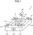
- FIG. 1 is a schematic view of an indoor monitoring system for a structure according to a first embodiment.
- FIG. 2 is a schematic view illustrating an aspect of inspection of a boiler furnace according to the first embodiment.
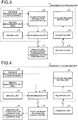
- FIG. 3 is a block configuration diagram of an indoor monitoring system for a structure according to the first embodiment. As illustrated in FIGS.
- the indoor monitoring system for the structure is provided with: an unmanned floating machine 11 with propellers 22, for example, as a floating means which levitates and moves the unmanned floating machine inside a closed structure 50, for example, a boiler furnace or the like by remote control; a distance measurement unit (for example, a laser scanner, an ultrasonic sensor, or the like) 12 which is mounted to the unmanned floating machine 11 and measures a distance between the unmanned floating machine 11 and an inner wall surface of the structure 50; an inertial measurement unit (IMU) which is mounted to the unmanned floating machine 11 and obtains an attitude of a body of the unmanned floating machine; an imaging unit (a still image imaging unit 13A and a video imaging unit 13B) 13 which is mounted to the unmanned floating machine 11 and images a structure (for example, piping, fitting or the like) on a wall surface side of the structure 50; an operation unit 15 which remotely controls the unmanned floating machine 11; a flight position information acquisition unit 16 which acquires current position information of the
- the flight position information acquisition unit 16 is configured to execute: a distance measuring step (step 1: S-1) of measuring a horizontal distance information (r(t), ⁇ s ) between the unmanned floating machine 11 and the inner wall surface of the structure 50 using the distance measurement unit 12; an attitude angle acquiring step (step 2: S-2) of acquiring an attitude angle of the unmanned floating machine 11 using the inertial measurement unit; a distance correcting step (step 3: S-3) of correcting the horizontal distance information (r(t), ⁇ s ) using the attitude angle acquired in step 2; a distance acquiring step (step 4: S-4) of acquiring distances of at least two points (any two points among front (L f (t)) and left (L L (t)), front (L f (t)) and right (L R (t)), back (L B (t)) and left (L L (t)), and back (L B (t)) and right (L R (t))) on the front, back, right and left of the unmanned floating machine 11
- the structure 50 which has a simple shape (whose cross-sectional shape is a rectangle or a circle), for example, a boiler furnace, a stack, or the like, is set as a target of inspection. Since the inside of the structure 50 is the target, provided is a system that monitors a flight position (current flight position information) of the unmanned floating machine 11 using the distance measurement unit (for example, the laser scanner, the ultrasonic sensor, or the like) 12 which does not use a GPS and the inertial measurement unit (IMU) which belongs a sensor group used for attitude control of the unmanned floating machine 11.
- the distance measurement unit for example, the laser scanner, the ultrasonic sensor, or the like
- IMU inertial measurement unit
- the unmanned floating machine 11 is operated by the operation unit 15 while confirming the flight position of the unmanned floating machine 11 and an image (a damaged portion) using the monitor unit 14 of a personal computer PC in a ground station positioned outside the closed structure (boiler furnace) 50, thereby performing inspection of an inner wall of a closed space of the boiler furnace 50, as illustrated in FIG. 2 .
- the unmanned floating machine 11 is introduced from an entrance of the boiler furnace 50 illustrated in FIG. 2 , thereafter is raised by a predetermined distance inside the boiler furnace 50, and is turned along inner surfaces of walls in the four directions by operating the operation unit 15 on the ground side. Thereafter, the unmanned floating machine 11 is raised again by a predetermined distance, and is turned along the inner wall surfaces in the four directions in the same manner. This operation is repeated until the top of the boiler furnace 50 is inspected, and then, the unmanned floating machine 11 is lowered, thereby ending the inspection.
- a degree of damage such as a crack in the piping on the inner surface is inspected using the imaging unit. During this inspection, it is possible to confirm the flight position and the damaged portion of the closed indoor structure on the monitor unit 14 according to the present embodiment, and thus, it is possible to perform unmanned inspection that reliably obtains the internal position information.
- the perimeter of the unmanned floating machine 11 is protected by an body guard portion 21 (a front-side guard portion 21A, a left-side guard portion 21B, a right-side guard portion 21C, and a back-side guard portion 21D), and there is provided the propeller 22 as the floating means on each upper surface of four corners of the body guard portion 21, the distance measurement unit 12 mounted at a center portion of a body 21E, the still image imaging unit 13A positioned on a part of the front-side guard portion 21A, and the video imaging unit 13B positioned on the back-side guard portion 21D via a support portion 13b, as illustrated in FIG. 1 .
- the distance measurement unit 12 scans a predetermined angle ( ⁇ 135° in the present embodiment) and can be turned by a turning means (not illustrated).
- any one of the still image imaging unit 13A and the video imaging unit 13B may be used as the imaging unit 13 to confirm the internal information.
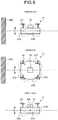
- FIG. 6 is a diagram illustrating three aspects of an attitude position of the unmanned floating machine according to the first embodiment.
- the inertial measurement unit is a device that detects angles (or angular velocities) and accelerations in three axes governing a motion.
- the upper stage of FIG. 6 illustrates an aspect of vertical rotation of the unmanned floating machine 11 which is turning (the pitch ( ⁇ )) where the front-side guard portion 21A (on a nose side) facing the inner wall 50a side is raised or lowered.
- the middle stage of FIG. 6 illustrates an aspect of horizontal rotation of the body of the unmanned floating machine 11 which is turning (the yaw ( ⁇ )) where a direction of a nose is shifted right and left, and the left-side guard portion 21B and the right-side guard portion 21C swing right and left.
- the lower stage of FIG. 6 is an aspect of rotation about an axis in a travel direction of the unmanned floating machine 11 which is turning (the roll ( ⁇ )) where the body is tilted right and left. Incidentally, the right and left of the body are based on the travel direction thereof.
- the flight position information acquisition unit 16 is configured to obtain a real distance based on actual distance information of the distance measurement unit 12 and the attitude angle information of the inertial measurement unit (IMU). This is because there is a need for correction of the measured distance since the unmanned floating machine 11 is not always capable of flying constantly according to XY coordinates.
- IMU inertial measurement unit
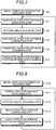
- FIG. 7 is a flowchart of position monitoring in the horizontal direction according to the first embodiment.
- the measurement in the horizontal direction is performed through step 1 (S-1) to step 5 (S-5).
- an initial direction information acquiring step (S-0) of acquiring initial direction information, obtained when the unmanned floating machine 11 is positioned at the bottom inside the structure 50, is provided in the present embodiment, but this step may be omitted.
- step 1 (S-1) it is possible to acquire the real distance information in the horizontal direction on consideration of the attitude angle at the time of measurement of the unmanned floating machine 11 by executing step 1 (S-1) to step 5 (S-5).
- step 3 the correction of the measured distance using the attitude angle acquired in step 3 (S-3) is performed as follows.
- a laser measurement point obtained as (r(t), ⁇ S ) is transformed into coordinates (x R ,y R ).
- This coordinate transformation is obtained by the following Formula (1).
- x R t y R t r t cos ⁇ s r t sin ⁇ s
- a value obtained from Formula (2) is transformed into a coordinate system (r, ⁇ ) of laser measurement.
- each distance on the front, back, right and left of the unmanned floating machine 11 is obtained on the basis of the yaw angle ⁇ (t) acquired by the inertial measurement unit (IMU) in step 4 (S-4).
- IMU inertial measurement unit
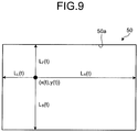
- a current position (x(t),y(t)) is acquired from the existing horizontal cross-sectional shape using measurable distances (at least two of the front, back, right and left distance).
- FIG. 8 is a flowchart of position monitoring in the height direction according to the first embodiment.
- An initial direction information acquiring step (S-10) of acquiring an initial direction information uses the information obtained in the initial direction information acquiring step (S-0) of acquiring the initial direction information in the horizontal direction.
- the measurement in the height direction is performed through the following step 11 (S-11) to step 14 (S-14).
- a corrected measurement point (z'(t)) is obtained from the following Formula (4).
- z ⁇ z cos ⁇ cos ⁇
- FIG. 3 is a block configuration diagram of an indoor monitoring system for a structure according to the first embodiment.
- FIG. 4 is a block configuration diagram of another indoor monitoring system for a structure according to the first embodiment.
- the present embodiment is a case in which position information processing is executed on the unmanned floating machine 11 side.
- the flight position information acquisition unit 16 is mounted at a predetermined portion (not illustrated) on the unmanned floating machine 11 side, and here, acquires real current position information and transmits the acquired real current position information to the ground side by a transmission unit 13a to display the information on the monitor unit 14.
- the operation of the unmanned floating machine 11 is performed in such a manner that a reception unit 15a receives a signal from the operation unit 15 and a flight command is issued to a floating machine driving unit 19.
- the imaging information of the imaging unit 13 (the still image imaging unit 13A and the video imaging unit 13B) 13 is transmitted to the ground side by the transmission unit 13a at the same time and displayed on the monitor unit 14 in the present embodiment.
- FIG. 4 Another example illustrated in FIG. 4 is a case in which the position information processing is performed on a controller terminal side of the personal computer PC on the ground.
- the flight position information acquisition unit 16 is mounted to the controller terminal of the PC on the ground side (base station), and information (signal) of the distance measurement unit 12 and information (signal) of the inertial measurement unit (IMU) are transmitted to the ground side by the transmission unit 13a. Further, the received information is processed by the flight position information acquisition unit 16 to acquire real current position information, and this acquired current position information is displayed on the monitor unit 14.
- the present invention is not limited thereto, and for example, may be configured such that the imaging information is temporarily stored in a memory unit of the imaging unit on the unmanned floating machine 11 side, the information is transmitted to the ground station side after ending measurement, and the imaging information and the position information are processed to match each other.
- the unmanned inspection which reliably obtains the position information inside the structure 50, for example, the boiler furnace, the stack, or the like, and it is possible to achieve the significant reduction of efforts, cost, inspection periods by omitting erection of scaffolding, for example, according to the present embodiment.
- the present invention is not limited thereto, and the accuracy in position measurement may be improved based on measurement information at multiple points.
- multiple points are extracted and averaged based on the scan angle in the distance measurement unit 12 to obtain each distance in the calculation of distances in the horizontal direction and the height direction. Further, when more than half of the multiple points is abnormal for distance measurement or unmeasurable, such points are not used for the position monitoring.
Landscapes
- Engineering & Computer Science (AREA)
- Radar, Positioning & Navigation (AREA)
- Remote Sensing (AREA)
- Physics & Mathematics (AREA)
- General Physics & Mathematics (AREA)
- Aviation & Aerospace Engineering (AREA)
- Automation & Control Theory (AREA)
- Chemical & Material Sciences (AREA)
- Health & Medical Sciences (AREA)
- Life Sciences & Earth Sciences (AREA)
- Analytical Chemistry (AREA)
- Biochemistry (AREA)
- General Health & Medical Sciences (AREA)
- Immunology (AREA)
- Pathology (AREA)
- Electromagnetism (AREA)
- Control Of Position, Course, Altitude, Or Attitude Of Moving Bodies (AREA)
- Studio Devices (AREA)
- Closed-Circuit Television Systems (AREA)
- Length Measuring Devices By Optical Means (AREA)
Applications Claiming Priority (2)
| Application Number | Priority Date | Filing Date | Title |
|---|---|---|---|
| JP2014136868A JP6486024B2 (ja) | 2014-07-02 | 2014-07-02 | 構造物の屋内監視システム及び方法 |
| PCT/JP2015/051360 WO2016002236A1 (fr) | 2014-07-02 | 2015-01-20 | Système et procédé de surveillance d'intérieur pour structure |
Publications (3)
| Publication Number | Publication Date |
|---|---|
| EP3147743A1 true EP3147743A1 (fr) | 2017-03-29 |
| EP3147743A4 EP3147743A4 (fr) | 2017-05-31 |
| EP3147743B1 EP3147743B1 (fr) | 2019-04-03 |
Family
ID=55018806
Family Applications (1)
| Application Number | Title | Priority Date | Filing Date |
|---|---|---|---|
| EP15814504.5A Active EP3147743B1 (fr) | 2014-07-02 | 2015-01-20 | Système et procédé de surveillance d'intérieur pour structure |
Country Status (6)
| Country | Link |
|---|---|
| US (1) | US10359778B2 (fr) |
| EP (1) | EP3147743B1 (fr) |
| JP (1) | JP6486024B2 (fr) |
| CN (1) | CN106662880B (fr) |
| TW (1) | TWI578132B (fr) |
| WO (1) | WO2016002236A1 (fr) |
Families Citing this family (33)
| Publication number | Priority date | Publication date | Assignee | Title |
|---|---|---|---|---|
| WO2017138049A1 (fr) * | 2016-02-10 | 2017-08-17 | パナソニックIpマネジメント株式会社 | Corps volant et système de commande associé |
| WO2017169516A1 (fr) * | 2016-03-28 | 2017-10-05 | 日本電気株式会社 | Système de commande de dispositif de vol sans pilote, procédé de commande de dispositif de vol sans pilote, et dispositif d'inspection |
| JP6710114B2 (ja) * | 2016-06-21 | 2020-06-17 | 株式会社日立製作所 | 管路施設点検飛行体と、それを用いた管路施設点検システム |
| JP6697821B2 (ja) * | 2016-07-21 | 2020-05-27 | 三菱重工機械システム株式会社 | 画像処理装置および画像処理方法 |
| JP6746137B2 (ja) * | 2016-11-02 | 2020-08-26 | 株式会社プロドローン | 無人航空機 |
| CN106500611A (zh) * | 2016-11-25 | 2017-03-15 | 重庆科技学院 | 测距仪辅助装置 |
| JP2018116443A (ja) * | 2017-01-18 | 2018-07-26 | 住友重機械工業株式会社 | 検査システム |
| CN110366670B (zh) * | 2017-03-02 | 2021-10-26 | 深圳市大疆创新科技有限公司 | 三维形状推断方法、飞行体、移动平台、程序及记录介质 |
| CN110392819B (zh) * | 2017-03-12 | 2022-02-01 | 株式会社尼罗沃克 | 用于测量农场水深的无人机 |
| JP6822267B2 (ja) * | 2017-03-28 | 2021-01-27 | 富士通株式会社 | 飛翔機及び飛翔機の使用方法 |
| JP6729879B2 (ja) * | 2017-04-06 | 2020-07-29 | 株式会社自律制御システム研究所 | 無人航空機、及びこれを用いる方法 |
| TWI662505B (zh) * | 2017-07-28 | 2019-06-11 | 中華大學 | 菌類生長影像監控系統 |
| CN109561275A (zh) * | 2017-09-27 | 2019-04-02 | 湖南航天远望科技有限公司 | 一种基于圆周扫描的区域监控方法及区域监控系统 |
| US20200364954A1 (en) * | 2017-09-28 | 2020-11-19 | Optim Corporation | Maintenance device control system, maintenance device control method, and program |
| JP7063578B2 (ja) * | 2017-11-09 | 2022-05-09 | 株式会社Soken | 飛行装置 |
| JP6475377B1 (ja) * | 2018-03-14 | 2019-02-27 | 株式会社サンメイ | 煙突の内部を検査する検査システム、および煙突の内部を検査する方法 |
| JP7033969B2 (ja) * | 2018-03-19 | 2022-03-11 | 三菱重工業株式会社 | 無人飛行体 |
| CN109031312B (zh) * | 2018-04-26 | 2023-08-22 | 中国计量大学 | 适用于烟囱内部作业的飞行平台定位装置和定位方法 |
| JP6505927B1 (ja) * | 2018-07-24 | 2019-04-24 | ミスギ工業株式会社 | 無人小型飛行体を用いた点検方法及びこれに用いる無人小型飛行体 |
| JP2020094780A (ja) * | 2018-12-14 | 2020-06-18 | 三菱重工機械システム株式会社 | 煙突筒身内面点検システム |
| WO2020139195A1 (fr) * | 2018-12-27 | 2020-07-02 | Performance Rotors Pte. Ltd. | Drone destiné à une inspection de défauts de surface |
| JP7213104B2 (ja) * | 2019-02-27 | 2023-01-26 | 三菱重工業株式会社 | 無人航空機および検査方法 |
| JP6733925B2 (ja) * | 2019-03-27 | 2020-08-05 | ミスギ工業株式会社 | 無人小型飛行体を用いた点検方法及びこれに用いる無人小型飛行体 |
| JP6737521B2 (ja) * | 2019-08-27 | 2020-08-12 | 株式会社センシンロボティクス | 高さ位置取得システム及び撮像システム、高さ位置取得方法、撮像方法 |
| JP6604681B1 (ja) | 2019-09-11 | 2019-11-13 | 株式会社Liberaware | 寸法表示システムおよび寸法表示方法 |
| JP6715542B1 (ja) * | 2019-10-28 | 2020-07-01 | 株式会社センシンロボティクス | 飛行体、点検方法及び点検システム |
| JP6777804B1 (ja) * | 2019-11-22 | 2020-10-28 | 三菱パワー株式会社 | ボイラ内部検査方法 |
| JP2021066420A (ja) * | 2020-06-02 | 2021-04-30 | 株式会社センシンロボティクス | 飛行体、点検方法及び点検システム |
| JP7612149B2 (ja) * | 2020-12-24 | 2025-01-14 | 株式会社Liberaware | 製鉄用加熱炉の検査方法 |
| CN112729312A (zh) * | 2020-12-25 | 2021-04-30 | 云南电网有限责任公司昆明供电局 | 一种变电站高压室无人机巡视方法 |
| JP7602952B2 (ja) * | 2021-03-31 | 2024-12-19 | 関西電力株式会社 | データ取得装置および該方法 |
| CN113483616B (zh) * | 2021-07-06 | 2023-03-14 | 重庆市地质矿产勘查开发局208水文地质工程地质队(重庆市地质灾害防治工程勘查设计院) | 用于地表裂缝的便携式快速装拆精准监测仪 |
| JP7594753B2 (ja) * | 2023-05-17 | 2024-12-05 | 国立大学法人徳島大学 | 円筒構造体の点検システム |
Family Cites Families (27)
| Publication number | Priority date | Publication date | Assignee | Title |
|---|---|---|---|---|
| JP3153832B2 (ja) | 1992-08-26 | 2001-04-09 | 三菱重工業株式会社 | 煙突の清掃装置 |
| JP2001209426A (ja) * | 2000-01-26 | 2001-08-03 | Nippon Telegr & Teleph Corp <Ntt> | 移動体制御装置 |
| JP2004211995A (ja) * | 2003-01-07 | 2004-07-29 | Mitsubishi Heavy Ind Ltd | 密閉空間内検査システム |
| CA2484422A1 (fr) | 2004-10-08 | 2006-04-08 | Furgro Airborne Surveys | Vehicule aeroporte sans pilote pour leve geophysique |
| JP4386367B2 (ja) * | 2006-02-08 | 2009-12-16 | 株式会社国際電気通信基礎技術研究所 | コミュニケーションロボット改良システム |
| EP1901153A1 (fr) | 2006-09-12 | 2008-03-19 | OFFIS e.V. | Système de contrôle pour un hélicoptère sans pilote avec 4 rotors |
| JP2009093308A (ja) * | 2007-10-05 | 2009-04-30 | Hitachi Industrial Equipment Systems Co Ltd | ロボットシステム |
| JP5105596B2 (ja) * | 2007-10-30 | 2012-12-26 | 株式会社Ihi | 自律走行移動体の走行経路決定用地図作成装置及び走行経路決定用地図作成方法 |
| JP2009136987A (ja) * | 2007-12-10 | 2009-06-25 | Toyota Motor Corp | 移動ロボット、及び床面形状データの補正方法 |
| JP5349804B2 (ja) * | 2008-01-10 | 2013-11-20 | 株式会社日立産機システム | 移動ロボットシステム及びその制御方法 |
| US8060270B2 (en) | 2008-02-29 | 2011-11-15 | The Boeing Company | System and method for inspection of structures and objects by swarm of remote unmanned vehicles |
| JP2009294713A (ja) * | 2008-06-02 | 2009-12-17 | Sanyo Electric Co Ltd | 点検システム、制御装置、点検方法及び制御プログラム |
| JP5141507B2 (ja) | 2008-08-25 | 2013-02-13 | 村田機械株式会社 | 自律移動装置 |
| FR2938774A1 (fr) | 2008-11-27 | 2010-05-28 | Parrot | Dispositif de pilotage d'un drone |
| US20140061376A1 (en) | 2010-05-26 | 2014-03-06 | Aerovironment Inc | Reconfigurable battery-operated vehicle system |
| EP2576342A4 (fr) * | 2010-05-26 | 2014-08-20 | Aerovironment Inc | Système de véhicule reconfigurable fonctionnant sur batterie |
| JP5614844B2 (ja) * | 2011-04-26 | 2014-10-29 | 学校法人千葉工業大学 | マルチロータヘリコプタの横風安定化装置及びこれを備えたマルチロータヘリコプタ |
| CN102435188B (zh) * | 2011-09-15 | 2013-10-02 | 南京航空航天大学 | 一种用于室内环境的单目视觉/惯性全自主导航方法 |
| CN202600150U (zh) | 2012-05-17 | 2012-12-12 | 北京必威易激光科技有限公司 | 智能化低空遥感测绘系统 |
| CN103455036B (zh) | 2012-06-05 | 2018-04-27 | 国家电网公司 | 一种场景空中巡视方法和飞行器 |
| JP6029446B2 (ja) * | 2012-12-13 | 2016-11-24 | セコム株式会社 | 自律飛行ロボット |
| CN103144770B (zh) * | 2013-03-19 | 2015-10-28 | 南京航空航天大学 | 一种全自主控制入室环境避障导航微型飞行器 |
| CN103365295B (zh) | 2013-06-29 | 2015-09-30 | 天津大学 | 基于dsp的四旋翼无人飞行器自主悬停控制系统及方法 |
| CN203342367U (zh) | 2013-07-01 | 2013-12-18 | 昊翔电能运动科技(昆山)有限公司 | 多轴飞行器 |
| CN107203219B (zh) * | 2013-07-05 | 2020-10-23 | 深圳市大疆创新科技有限公司 | 无人飞行器的飞行辅助系统和方法 |
| CN103697889B (zh) | 2013-12-29 | 2016-05-25 | 北京航空航天大学 | 一种基于多模型分布式滤波的无人机自主导航与定位方法 |
| WO2015107623A1 (fr) * | 2014-01-15 | 2015-07-23 | パイオニア株式会社 | Système de gestion et procédé de spécification de positions |
-
2014
- 2014-07-02 JP JP2014136868A patent/JP6486024B2/ja active Active
-
2015
- 2015-01-20 WO PCT/JP2015/051360 patent/WO2016002236A1/fr not_active Ceased
- 2015-01-20 CN CN201580034665.7A patent/CN106662880B/zh active Active
- 2015-01-20 US US15/322,230 patent/US10359778B2/en active Active
- 2015-01-20 EP EP15814504.5A patent/EP3147743B1/fr active Active
- 2015-01-27 TW TW104102689A patent/TWI578132B/zh active
Also Published As
| Publication number | Publication date |
|---|---|
| JP6486024B2 (ja) | 2019-03-20 |
| WO2016002236A1 (fr) | 2016-01-07 |
| JP2016015628A (ja) | 2016-01-28 |
| EP3147743A4 (fr) | 2017-05-31 |
| TW201602748A (zh) | 2016-01-16 |
| US10359778B2 (en) | 2019-07-23 |
| CN106662880B (zh) | 2019-08-06 |
| CN106662880A (zh) | 2017-05-10 |
| TWI578132B (zh) | 2017-04-11 |
| US20170139410A1 (en) | 2017-05-18 |
| EP3147743B1 (fr) | 2019-04-03 |
Similar Documents
| Publication | Publication Date | Title |
|---|---|---|
| EP3147743B1 (fr) | Système et procédé de surveillance d'intérieur pour structure | |
| EP3460392B1 (fr) | Système de positionnement pour une inspection aérienne non destructive | |
| US10656096B2 (en) | Method and system for inspecting a surface area for material defects | |
| EP3474109B1 (fr) | Dispositif de mesure, dispositif de commande pour véhicule aérien sans pilote et procédé pour commander un véhicule aérien sans pilote | |
| JP6375503B2 (ja) | 飛行型検査装置および検査方法 | |
| CN110915202A (zh) | 引导信息显示装置和具备该装置的起重机、引导信息显示方法 | |
| CN112327898B (zh) | 无人机的井道巡检导航方法、装置和无人机 | |
| US11913789B2 (en) | Inspection management device, inspection management method, and recording medium to store program | |
| US9334031B2 (en) | System for attitude control of underwater vehicle and method for attitude control of underwater vehicle | |
| EP4063985A1 (fr) | Système de drone d'inspection | |
| US11490005B2 (en) | Overhead line image capturing system and overhead line image capturing method | |
| KR101664909B1 (ko) | 태양광 패널의 형상을 활용한 태양광 패널 감시용 무인 비행체 및 그의 자세 제어 방법 | |
| US20220099442A1 (en) | Surveying System | |
| KR101970789B1 (ko) | 파이프 위치 및 자세 탐지 장치와 이를 이용한 파이프 위치 및 자세 탐지 방법 | |
| JP7207164B2 (ja) | 巡視点検システム | |
| JP2008057243A (ja) | 橋梁架設施工管理方法及び装置 | |
| KR101702517B1 (ko) | 의장품 돌출부 검사 장치 | |
| JP2023070120A (ja) | 自律飛行制御方法、自律飛行制御装置および自律飛行制御システム | |
| CN102285590B (zh) | 基于红外结构光的集装箱吊具抓箱作业感知系统及方法 | |
| KR20220145448A (ko) | 3차원 레이저 스캐너를 이용한 항공기 주기유도 시스템 및 이를 이용한 항공기 주기 제어방법 | |
| WO2021008912A1 (fr) | Procédé de réalisation d'une inspection et système embarqué associé | |
| US20240111311A1 (en) | Control apparatus, base station, control method, and program | |
| US20250150559A1 (en) | Moving wind turbine blade inspection | |
| CN202164053U (zh) | 基于红外结构光的集装箱吊具抓箱作业智能感知系统 | |
| JP6715542B1 (ja) | 飛行体、点検方法及び点検システム |
Legal Events
| Date | Code | Title | Description |
|---|---|---|---|
| STAA | Information on the status of an ep patent application or granted ep patent |
Free format text: STATUS: THE INTERNATIONAL PUBLICATION HAS BEEN MADE |
|
| PUAI | Public reference made under article 153(3) epc to a published international application that has entered the european phase |
Free format text: ORIGINAL CODE: 0009012 |
|
| STAA | Information on the status of an ep patent application or granted ep patent |
Free format text: STATUS: REQUEST FOR EXAMINATION WAS MADE |
|
| 17P | Request for examination filed |
Effective date: 20161223 |
|
| AK | Designated contracting states |
Kind code of ref document: A1 Designated state(s): AL AT BE BG CH CY CZ DE DK EE ES FI FR GB GR HR HU IE IS IT LI LT LU LV MC MK MT NL NO PL PT RO RS SE SI SK SM TR |
|
| AX | Request for extension of the european patent |
Extension state: BA ME |
|
| A4 | Supplementary search report drawn up and despatched |
Effective date: 20170503 |
|
| RIC1 | Information provided on ipc code assigned before grant |
Ipc: G01C 15/00 20060101ALI20170425BHEP Ipc: G05D 1/10 20060101AFI20170425BHEP Ipc: G01B 21/00 20060101ALI20170425BHEP Ipc: G01N 21/84 20060101ALI20170425BHEP Ipc: G05D 1/00 20060101ALI20170425BHEP |
|
| DAX | Request for extension of the european patent (deleted) | ||
| STAA | Information on the status of an ep patent application or granted ep patent |
Free format text: STATUS: EXAMINATION IS IN PROGRESS |
|
| 17Q | First examination report despatched |
Effective date: 20180122 |
|
| GRAP | Despatch of communication of intention to grant a patent |
Free format text: ORIGINAL CODE: EPIDOSNIGR1 |
|
| STAA | Information on the status of an ep patent application or granted ep patent |
Free format text: STATUS: GRANT OF PATENT IS INTENDED |
|
| INTG | Intention to grant announced |
Effective date: 20180926 |
|
| GRAS | Grant fee paid |
Free format text: ORIGINAL CODE: EPIDOSNIGR3 |
|
| GRAJ | Information related to disapproval of communication of intention to grant by the applicant or resumption of examination proceedings by the epo deleted |
Free format text: ORIGINAL CODE: EPIDOSDIGR1 |
|
| GRAL | Information related to payment of fee for publishing/printing deleted |
Free format text: ORIGINAL CODE: EPIDOSDIGR3 |
|
| STAA | Information on the status of an ep patent application or granted ep patent |
Free format text: STATUS: EXAMINATION IS IN PROGRESS |
|
| GRAR | Information related to intention to grant a patent recorded |
Free format text: ORIGINAL CODE: EPIDOSNIGR71 |
|
| STAA | Information on the status of an ep patent application or granted ep patent |
Free format text: STATUS: GRANT OF PATENT IS INTENDED |
|
| GRAA | (expected) grant |
Free format text: ORIGINAL CODE: 0009210 |
|
| STAA | Information on the status of an ep patent application or granted ep patent |
Free format text: STATUS: THE PATENT HAS BEEN GRANTED |
|
| INTC | Intention to grant announced (deleted) | ||
| INTG | Intention to grant announced |
Effective date: 20190220 |
|
| AK | Designated contracting states |
Kind code of ref document: B1 Designated state(s): AL AT BE BG CH CY CZ DE DK EE ES FI FR GB GR HR HU IE IS IT LI LT LU LV MC MK MT NL NO PL PT RO RS SE SI SK SM TR |
|
| REG | Reference to a national code |
Ref country code: GB Ref legal event code: FG4D |
|
| REG | Reference to a national code |
Ref country code: CH Ref legal event code: EP Ref country code: AT Ref legal event code: REF Ref document number: 1116515 Country of ref document: AT Kind code of ref document: T Effective date: 20190415 |
|
| REG | Reference to a national code |
Ref country code: DE Ref legal event code: R096 Ref document number: 602015027737 Country of ref document: DE |
|
| REG | Reference to a national code |
Ref country code: IE Ref legal event code: FG4D |
|
| REG | Reference to a national code |
Ref country code: NL Ref legal event code: MP Effective date: 20190403 |
|
| REG | Reference to a national code |
Ref country code: LT Ref legal event code: MG4D |
|
| REG | Reference to a national code |
Ref country code: AT Ref legal event code: MK05 Ref document number: 1116515 Country of ref document: AT Kind code of ref document: T Effective date: 20190403 |
|
| PG25 | Lapsed in a contracting state [announced via postgrant information from national office to epo] |
Ref country code: NL Free format text: LAPSE BECAUSE OF FAILURE TO SUBMIT A TRANSLATION OF THE DESCRIPTION OR TO PAY THE FEE WITHIN THE PRESCRIBED TIME-LIMIT Effective date: 20190403 |
|
| PG25 | Lapsed in a contracting state [announced via postgrant information from national office to epo] |
Ref country code: AL Free format text: LAPSE BECAUSE OF FAILURE TO SUBMIT A TRANSLATION OF THE DESCRIPTION OR TO PAY THE FEE WITHIN THE PRESCRIBED TIME-LIMIT Effective date: 20190403 Ref country code: PT Free format text: LAPSE BECAUSE OF FAILURE TO SUBMIT A TRANSLATION OF THE DESCRIPTION OR TO PAY THE FEE WITHIN THE PRESCRIBED TIME-LIMIT Effective date: 20190803 Ref country code: SE Free format text: LAPSE BECAUSE OF FAILURE TO SUBMIT A TRANSLATION OF THE DESCRIPTION OR TO PAY THE FEE WITHIN THE PRESCRIBED TIME-LIMIT Effective date: 20190403 Ref country code: FI Free format text: LAPSE BECAUSE OF FAILURE TO SUBMIT A TRANSLATION OF THE DESCRIPTION OR TO PAY THE FEE WITHIN THE PRESCRIBED TIME-LIMIT Effective date: 20190403 Ref country code: NO Free format text: LAPSE BECAUSE OF FAILURE TO SUBMIT A TRANSLATION OF THE DESCRIPTION OR TO PAY THE FEE WITHIN THE PRESCRIBED TIME-LIMIT Effective date: 20190703 Ref country code: HR Free format text: LAPSE BECAUSE OF FAILURE TO SUBMIT A TRANSLATION OF THE DESCRIPTION OR TO PAY THE FEE WITHIN THE PRESCRIBED TIME-LIMIT Effective date: 20190403 Ref country code: ES Free format text: LAPSE BECAUSE OF FAILURE TO SUBMIT A TRANSLATION OF THE DESCRIPTION OR TO PAY THE FEE WITHIN THE PRESCRIBED TIME-LIMIT Effective date: 20190403 Ref country code: LT Free format text: LAPSE BECAUSE OF FAILURE TO SUBMIT A TRANSLATION OF THE DESCRIPTION OR TO PAY THE FEE WITHIN THE PRESCRIBED TIME-LIMIT Effective date: 20190403 Ref country code: CZ Free format text: LAPSE BECAUSE OF FAILURE TO SUBMIT A TRANSLATION OF THE DESCRIPTION OR TO PAY THE FEE WITHIN THE PRESCRIBED TIME-LIMIT Effective date: 20190403 |
|
| PG25 | Lapsed in a contracting state [announced via postgrant information from national office to epo] |
Ref country code: LV Free format text: LAPSE BECAUSE OF FAILURE TO SUBMIT A TRANSLATION OF THE DESCRIPTION OR TO PAY THE FEE WITHIN THE PRESCRIBED TIME-LIMIT Effective date: 20190403 Ref country code: RS Free format text: LAPSE BECAUSE OF FAILURE TO SUBMIT A TRANSLATION OF THE DESCRIPTION OR TO PAY THE FEE WITHIN THE PRESCRIBED TIME-LIMIT Effective date: 20190403 Ref country code: BG Free format text: LAPSE BECAUSE OF FAILURE TO SUBMIT A TRANSLATION OF THE DESCRIPTION OR TO PAY THE FEE WITHIN THE PRESCRIBED TIME-LIMIT Effective date: 20190703 Ref country code: PL Free format text: LAPSE BECAUSE OF FAILURE TO SUBMIT A TRANSLATION OF THE DESCRIPTION OR TO PAY THE FEE WITHIN THE PRESCRIBED TIME-LIMIT Effective date: 20190403 Ref country code: GR Free format text: LAPSE BECAUSE OF FAILURE TO SUBMIT A TRANSLATION OF THE DESCRIPTION OR TO PAY THE FEE WITHIN THE PRESCRIBED TIME-LIMIT Effective date: 20190704 |
|
| PG25 | Lapsed in a contracting state [announced via postgrant information from national office to epo] |
Ref country code: IS Free format text: LAPSE BECAUSE OF FAILURE TO SUBMIT A TRANSLATION OF THE DESCRIPTION OR TO PAY THE FEE WITHIN THE PRESCRIBED TIME-LIMIT Effective date: 20190803 Ref country code: AT Free format text: LAPSE BECAUSE OF FAILURE TO SUBMIT A TRANSLATION OF THE DESCRIPTION OR TO PAY THE FEE WITHIN THE PRESCRIBED TIME-LIMIT Effective date: 20190403 |
|
| REG | Reference to a national code |
Ref country code: DE Ref legal event code: R097 Ref document number: 602015027737 Country of ref document: DE |
|
| PG25 | Lapsed in a contracting state [announced via postgrant information from national office to epo] |
Ref country code: DK Free format text: LAPSE BECAUSE OF FAILURE TO SUBMIT A TRANSLATION OF THE DESCRIPTION OR TO PAY THE FEE WITHIN THE PRESCRIBED TIME-LIMIT Effective date: 20190403 Ref country code: EE Free format text: LAPSE BECAUSE OF FAILURE TO SUBMIT A TRANSLATION OF THE DESCRIPTION OR TO PAY THE FEE WITHIN THE PRESCRIBED TIME-LIMIT Effective date: 20190403 Ref country code: SK Free format text: LAPSE BECAUSE OF FAILURE TO SUBMIT A TRANSLATION OF THE DESCRIPTION OR TO PAY THE FEE WITHIN THE PRESCRIBED TIME-LIMIT Effective date: 20190403 Ref country code: RO Free format text: LAPSE BECAUSE OF FAILURE TO SUBMIT A TRANSLATION OF THE DESCRIPTION OR TO PAY THE FEE WITHIN THE PRESCRIBED TIME-LIMIT Effective date: 20190403 |
|
| PLBE | No opposition filed within time limit |
Free format text: ORIGINAL CODE: 0009261 |
|
| STAA | Information on the status of an ep patent application or granted ep patent |
Free format text: STATUS: NO OPPOSITION FILED WITHIN TIME LIMIT |
|
| PG25 | Lapsed in a contracting state [announced via postgrant information from national office to epo] |
Ref country code: IT Free format text: LAPSE BECAUSE OF FAILURE TO SUBMIT A TRANSLATION OF THE DESCRIPTION OR TO PAY THE FEE WITHIN THE PRESCRIBED TIME-LIMIT Effective date: 20190403 Ref country code: SM Free format text: LAPSE BECAUSE OF FAILURE TO SUBMIT A TRANSLATION OF THE DESCRIPTION OR TO PAY THE FEE WITHIN THE PRESCRIBED TIME-LIMIT Effective date: 20190403 |
|
| 26N | No opposition filed |
Effective date: 20200106 |
|
| PG25 | Lapsed in a contracting state [announced via postgrant information from national office to epo] |
Ref country code: TR Free format text: LAPSE BECAUSE OF FAILURE TO SUBMIT A TRANSLATION OF THE DESCRIPTION OR TO PAY THE FEE WITHIN THE PRESCRIBED TIME-LIMIT Effective date: 20190403 |
|
| PG25 | Lapsed in a contracting state [announced via postgrant information from national office to epo] |
Ref country code: SI Free format text: LAPSE BECAUSE OF FAILURE TO SUBMIT A TRANSLATION OF THE DESCRIPTION OR TO PAY THE FEE WITHIN THE PRESCRIBED TIME-LIMIT Effective date: 20190403 |
|
| PG25 | Lapsed in a contracting state [announced via postgrant information from national office to epo] |
Ref country code: MC Free format text: LAPSE BECAUSE OF FAILURE TO SUBMIT A TRANSLATION OF THE DESCRIPTION OR TO PAY THE FEE WITHIN THE PRESCRIBED TIME-LIMIT Effective date: 20190403 |
|
| REG | Reference to a national code |
Ref country code: CH Ref legal event code: PL |
|
| REG | Reference to a national code |
Ref country code: BE Ref legal event code: MM Effective date: 20200131 |
|
| PG25 | Lapsed in a contracting state [announced via postgrant information from national office to epo] |
Ref country code: LU Free format text: LAPSE BECAUSE OF NON-PAYMENT OF DUE FEES Effective date: 20200120 |
|
| PG25 | Lapsed in a contracting state [announced via postgrant information from national office to epo] |
Ref country code: BE Free format text: LAPSE BECAUSE OF NON-PAYMENT OF DUE FEES Effective date: 20200131 Ref country code: LI Free format text: LAPSE BECAUSE OF NON-PAYMENT OF DUE FEES Effective date: 20200131 Ref country code: CH Free format text: LAPSE BECAUSE OF NON-PAYMENT OF DUE FEES Effective date: 20200131 |
|
| PG25 | Lapsed in a contracting state [announced via postgrant information from national office to epo] |
Ref country code: IE Free format text: LAPSE BECAUSE OF NON-PAYMENT OF DUE FEES Effective date: 20200120 |
|
| PG25 | Lapsed in a contracting state [announced via postgrant information from national office to epo] |
Ref country code: MT Free format text: LAPSE BECAUSE OF FAILURE TO SUBMIT A TRANSLATION OF THE DESCRIPTION OR TO PAY THE FEE WITHIN THE PRESCRIBED TIME-LIMIT Effective date: 20190403 Ref country code: CY Free format text: LAPSE BECAUSE OF FAILURE TO SUBMIT A TRANSLATION OF THE DESCRIPTION OR TO PAY THE FEE WITHIN THE PRESCRIBED TIME-LIMIT Effective date: 20190403 |
|
| PG25 | Lapsed in a contracting state [announced via postgrant information from national office to epo] |
Ref country code: MK Free format text: LAPSE BECAUSE OF FAILURE TO SUBMIT A TRANSLATION OF THE DESCRIPTION OR TO PAY THE FEE WITHIN THE PRESCRIBED TIME-LIMIT Effective date: 20190403 |
|
| REG | Reference to a national code |
Ref country code: DE Ref legal event code: R079 Ref document number: 602015027737 Country of ref document: DE Free format text: PREVIOUS MAIN CLASS: G05D0001100000 Ipc: G05D0001460000 |
|
| PGFP | Annual fee paid to national office [announced via postgrant information from national office to epo] |
Ref country code: GB Payment date: 20251127 Year of fee payment: 12 |
|
| PGFP | Annual fee paid to national office [announced via postgrant information from national office to epo] |
Ref country code: FR Payment date: 20251128 Year of fee payment: 12 |
|
| PGFP | Annual fee paid to national office [announced via postgrant information from national office to epo] |
Ref country code: DE Payment date: 20251203 Year of fee payment: 12 |