EP3147920B1 - Elektromagnetisches relais - Google Patents
Elektromagnetisches relais Download PDFInfo
- Publication number
- EP3147920B1 EP3147920B1 EP16162824.3A EP16162824A EP3147920B1 EP 3147920 B1 EP3147920 B1 EP 3147920B1 EP 16162824 A EP16162824 A EP 16162824A EP 3147920 B1 EP3147920 B1 EP 3147920B1
- Authority
- EP
- European Patent Office
- Prior art keywords
- pair
- electromagnetic relay
- contact
- fixed
- contacts
- Prior art date
- Legal status (The legal status is an assumption and is not a legal conclusion. Google has not performed a legal analysis and makes no representation as to the accuracy of the status listed.)
- Active
Links
Images




Classifications
-
- H—ELECTRICITY
- H01—ELECTRIC ELEMENTS
- H01H—ELECTRIC SWITCHES; RELAYS; SELECTORS; EMERGENCY PROTECTIVE DEVICES
- H01H9/00—Details of switching devices, not covered by groups H01H1/00 - H01H7/00
- H01H9/30—Means for extinguishing or preventing arc between current-carrying parts
- H01H9/44—Means for extinguishing or preventing arc between current-carrying parts using blow-out magnet
- H01H9/443—Means for extinguishing or preventing arc between current-carrying parts using blow-out magnet using permanent magnets
-
- H—ELECTRICITY
- H01—ELECTRIC ELEMENTS
- H01H—ELECTRIC SWITCHES; RELAYS; SELECTORS; EMERGENCY PROTECTIVE DEVICES
- H01H50/00—Details of electromagnetic relays
- H01H50/02—Bases; Casings; Covers
-
- H—ELECTRICITY
- H01—ELECTRIC ELEMENTS
- H01H—ELECTRIC SWITCHES; RELAYS; SELECTORS; EMERGENCY PROTECTIVE DEVICES
- H01H50/00—Details of electromagnetic relays
- H01H50/16—Magnetic circuit arrangements
- H01H50/18—Movable parts of magnetic circuits, e.g. armature
- H01H50/24—Parts rotatable or rockable outside coil
-
- H—ELECTRICITY
- H01—ELECTRIC ELEMENTS
- H01H—ELECTRIC SWITCHES; RELAYS; SELECTORS; EMERGENCY PROTECTIVE DEVICES
- H01H50/00—Details of electromagnetic relays
- H01H50/16—Magnetic circuit arrangements
- H01H50/36—Stationary parts of magnetic circuit, e.g. yoke
-
- H—ELECTRICITY
- H01—ELECTRIC ELEMENTS
- H01H—ELECTRIC SWITCHES; RELAYS; SELECTORS; EMERGENCY PROTECTIVE DEVICES
- H01H50/00—Details of electromagnetic relays
- H01H50/44—Magnetic coils or windings
-
- H—ELECTRICITY
- H01—ELECTRIC ELEMENTS
- H01H—ELECTRIC SWITCHES; RELAYS; SELECTORS; EMERGENCY PROTECTIVE DEVICES
- H01H50/00—Details of electromagnetic relays
- H01H50/02—Bases; Casings; Covers
- H01H50/04—Mounting complete relay or separate parts of relay on a base or inside a case
-
- H—ELECTRICITY
- H01—ELECTRIC ELEMENTS
- H01H—ELECTRIC SWITCHES; RELAYS; SELECTORS; EMERGENCY PROTECTIVE DEVICES
- H01H50/00—Details of electromagnetic relays
- H01H50/16—Magnetic circuit arrangements
- H01H50/18—Movable parts of magnetic circuits, e.g. armature
- H01H50/24—Parts rotatable or rockable outside coil
- H01H50/26—Parts movable about a knife edge
-
- H—ELECTRICITY
- H01—ELECTRIC ELEMENTS
- H01H—ELECTRIC SWITCHES; RELAYS; SELECTORS; EMERGENCY PROTECTIVE DEVICES
- H01H50/00—Details of electromagnetic relays
- H01H50/16—Magnetic circuit arrangements
- H01H50/18—Movable parts of magnetic circuits, e.g. armature
- H01H50/24—Parts rotatable or rockable outside coil
- H01H50/28—Parts movable due to bending of a blade spring or reed
-
- H—ELECTRICITY
- H01—ELECTRIC ELEMENTS
- H01H—ELECTRIC SWITCHES; RELAYS; SELECTORS; EMERGENCY PROTECTIVE DEVICES
- H01H50/00—Details of electromagnetic relays
- H01H50/54—Contact arrangements
- H01H50/56—Contact spring sets
- H01H50/58—Driving arrangements structurally associated therewith; Mounting of driving arrangements on armature
Definitions
- the present invention relates to an electromagnetic relay.
- an electromagnetic relay used for the switching control of an electric circuit of an on-vehicle electric power steering, i.e., an electric circuit through which relatively large inrush current (e.g., 60 A) flows at the moment when a contact is closed as disclosed in, for example, Japanese Patent Application Publication No. 2011-81961 .
- a relay capable of enhancing an arc-extinguishing effect as disclosed in, for example, Japanese Patent Application Publication No. 2011-154818 .
- the mild hybrid system uses an engine as a main power source, and uses a motor to assist the engine when the vehicle is stopped or started.
- EP2688083 discloses an electromagnetic relay provided with: a contact switching unit having a contact group comprising a pair of contacts that can touch and separate; an electromagnet block that drives the contact switching unit to open and close the contacts; and an arc-extinguishing member comprising a connection member formed by connecting, via a middle part, opposing walls arranged in a direction perpendicular to the touch/separation direction of the contacts, and also comprising permanent magnets disposed on the opposing sections of the opposing walls.
- Relays used for low voltage batteries can be configured to be small in size and light in weight.
- the relay when the relay is connected to a battery with a voltage exceeding an assumed voltage, for example, is connected to a DC48V battery, it is impossible to interrupt an arc generated in the relay.
- the relay cannot be used for a DC48V battery (i.e., a high voltage battery).
- the relay disclosed in Japanese Patent Application Publication No. 2011-154818 has a structure designed to drive a movable-side spring terminal via a card. Accordingly, the heat of the arc may distort the shape of the card, and the relay may malfunction.
- Relays used in circuits mounted on electric vehicles or large-scale direct current apparatuses have high arc-interrupting performance, but poor continuous current-carrying performance.
- the size of the relay increases.
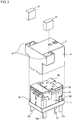
- FIG. 1 is an exploded perspective view of an electromagnetic relay in accordance with the embodiment
- FIG. 2 is a perspective view illustrating an assembly structure of the electromagnetic relay
- FIG. 3 and FIG. 4 are perspective views illustrating the assembly structure of the electromagnetic relay with a cover removed.
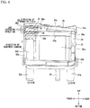
- FIG. 5 is a cross-sectional view illustrating the assembly structure of the electromagnetic relay (the cross-section in the front direction).
- FIG. 6 and FIG. 7 are cross-sectional views illustrating the assembly structure of the electromagnetic relay with the cover removed (the cross-section in the side direction).
- front-to-rear and right-to-left directions and a top-to-bottom direction are defined as illustrated in the drawings hereinafter, and the configuration of each component will be described in accordance with the definition.
- the electromagnetic relay of the present embodiment is used in a hybrid vehicle that employs the mild hybrid system and in which, for example, a DC48V battery is installed. More specifically, the electromagnetic relay of the present embodiment is used for the switching control of the control circuit of the DC48V battery, but may be used in many applications.
- An electromagnetic relay 50 of the present embodiment is a sealed hinge-type relay, and includes a base block 1, an electromagnet 2 embedded in the base block 1, a contact portion 3 that opens and closes in response to the operation of the electromagnet 2, and a cover 4 that covers the electromagnet 2 and the contact portion 3.
- FIG. 3 and FIG. 4 do not illustrate the cover 4.
- the contact portion 3 of FIG. 3 is configured as a so-called make contact, is opened at normal times, and is closed during the operation.
- the contact portion 3 is structured by a pair of movable contacts 30 and a pair of fixed contacts 34 described later. One of the movable contacts 30 and one of the fixed contacts 34 form a first contact pair, and the other of the movable contacts 30 and the other of the fixed contacts 34 form a second contact pair.
- the base block 1 illustrated in FIG. 1 is made of an electrically-insulating resin molded article, and includes an approximately rectangular frame portion 10 and a bottom portion 11 that closes the bottom surface of the frame portion 10.
- a recess portion 12 that is defined by the frame portion 10 and the bottom portion 11 and opens upward.
- the recess portion 12 fixedly supports the electromagnet 2 and the contact portion 3.
- the cover 4 is adhesively fixed to the frame portion 10 of the base block 1.
- the electromagnet 2 includes a hollow body 20g extended in the top-to-bottom direction, a spool 20 including an upper flange 20a located at the top of the spool 20 and a lower flange 20b located at the bottom of the spool 20, an iron core 21 accommodated in the hollow body 20g of the spool 20, and a coil 22 provided on the outer peripheral surface of the spool 20.
- the lower flange 20b of the spool 20 is fixedly supported by the recess portion 12 of the base block 1.
- a stepped portion 20c is formed in the central part of the upper flange 20a of the spool 20.
- a width narrowed portion 20h in which the width of the upper flange 20a in the right-to-left direction is narrowed.
- a pair of right and left side walls 20d are raised upward from the width narrowed portion 20h.
- the top end portion of the right side wall 20d is bent outward in the right direction.
- the right and left side surfaces of the top end portions of the side walls 20d and the right and left side surfaces of the upper flange 20a posterior to the side wall 20d are located on the same planes extending in the top-to-bottom direction in the drawing, respectively.
- an upper wall 20e parallel to the upper flange 20a is provided between the right and left side walls 20d.
- the upper flange 20a, the right and left side walls 20d, and the upper wall 20e form an approximately box-shaped space SP of which the front and rear faces open.
- slits 20f are formed from the front end face to the rear to be parallel to the upper wall 20e.
- the left slit 20f leaves the wall surface of the left side wall 20d at the left end, while the right slit 20f penetrates through the wall surface of the right side wall 20d in the right-to-left direction.
- the slits 20f are used to mount a backstop 33 described later.
- the spool 20 is configured as an electrically-insulating resin molded article, and all the portions (20a through 20h) are integrally formed.
- the iron core 21 is a columnar member formed from, for example, magnetic steel, and a top end face 21a of the iron core 21 is exposed to the outside from the upper flange 20a of the spool 20 while the iron core 21 is accommodated in the spool.
- the part of the iron core 21 excluding the top end face 21a is fixedly supported to the inside of the hollow body 20g.
- the winding wire of the coil 22 is wound around the outer peripheral surface of the hollow body 20g between the upper flange 20a and the lower flange 20b of the spool 20, and each of both ends of the coil 22 is connected to the corresponding one of a pair of right and left coil terminals 23 fixed to the base block 1.
- a yoke 24 is fixedly connected to the bottom end portion of the iron core 21 by, for example, swaging.
- the yoke 24 is a plate-like member formed by die-cutting and bending, for example, a magnetic steel sheet into an L-shape in cross section. In a state where the electromagnetic relay 50 is assembled, the yoke 24 extends below the lower flange 20b of the spool 20 in the front-to-rear direction, and extends behind the hollow body 20g of the spool 20 in the top-to-bottom direction.
- a top 24a of the yoke 24 is located at approximately the same height as the top end face 21a of the iron core 21, and the top 24a supports an armature 25.
- the armature 25 is a flat plate-like member formed by die-cutting, for example, a magnetic steel sheet, and is arranged approximately vertically above the upper flange 20a in the assembled state of the electromagnetic relay 50 as illustrated in FIG. 3 .
- the rear end portion of the armature 25 contacts the top 24a of the yoke 24 and is swingably supported, and the front bottom face of the armature 25 is arranged to be opposed to the top end face 21a of the iron core 21.
- This configuration allows a magnetic circuit to be formed among the iron core 21, the yoke 24, and the armature 25 when the electromagnet 2 operates.
- the armature 25 is mounted to a movable spring member 26 (a first member), and is connected resiliently relatively-movably to the yoke 24 via the movable spring member 26.
- the movable spring member 26 is a conductive plate spring member formed by die-cutting and bending, for example, a thin sheet of phosphor bronze for spring into an approximately L-shape. As illustrated in FIG.
- the movable spring member 26 integrally includes a vertical portion 26a fixed on the rear face of the yoke 24 by, for example, swaging, a horizontal portion 26b (a first horizontal portion) fixed on the top face of the armature 25 by, for example, swaging, a pair of right and left hinge springs 26c that is formed by bending, and connects the vertical portion 26a to the horizontal portion 26b, and a pair of right and left spring arms 26d that is branched from the horizontal portion 26b in the right-to-left direction and dichotomously extended frontward.
- the movable spring member 26 functions as a hinge that connects the yoke 24 and the armature 25 by elasticity, and biases the armature 25 in a direction away from the top end face 21a of the iron core 21 (upward) by the spring action of the hinge spring 26c.
- the movable contact 30 made from a predetermined contact material is mounted to the tip of each spring arm 26d by, for example, swaging. Accordingly, the number of the movable contacts 30 is two in total.
- the spring arms 26d of the movable spring member 26 are inserted into the space SP between the upper wall 20e and the upper flange 20a of the spool 20 from the rear side, and the movable contacts 30 are arranged in the space SP.
- the right and left ends of the vertical portion 26a of the movable spring member 26 form a pair of right and left terminals 31b (a first terminal) that is bent frontward at approximately a right angle and extended downward.
- the bent formed terminals 31b are arranged along right and left corner portions at the rear end of the recess portion 12 of the base block 1, and penetrate through the bottom portion 11 of the base block 1 in the top-to-bottom direction.
- a fixed terminal member 32 (a second member) is a conductive plate member formed by die-cutting and bending, for example, a copper sheet. As illustrated in FIG. 1 , the fixed terminal member 32 integrally includes a front plate portion 32a extended in front of the spool 20 in the vertical direction, a horizontal portion 32b (a second horizontal portion) formed by bending the top portion of the front plate portion 32a rearward at approximately a right angle, branched from the top portion of the front plate portion 32a in the right-to-left direction, and dichotomously extended, and a pair of right and left terminals 32c (a second terminal) formed by bending the right and left end portions of the front plate portion 32a rearward at approximately a right angle and extended lower than the front plate portion 32a.
- Each horizontal portion 32b is inserted into the space SP from the front side of the spool 20, and is positioned below the spring arm 26d of the movable spring member 26 in the assembled state of the electromagnetic relay as illustrated in FIG. 3 .
- the fixed contact 34 opposed to the corresponding movable contact 30 is mounted to the top face of each horizontal portion 32b by, for example, swaging. Accordingly, the number of the fixed contacts 34 is two in total.
- the bent formed terminals 32c are arranged along right and left corner portions at the front end of the recess portion 12 of the base block 1, and penetrate through the bottom portion 11 of the base block 1 in the top-to-bottom direction.
- the backstop 33 (a stopper) is a conductive plate member formed by die-cutting and bending, for example, a copper sheet.
- the backstop 33 integrally includes a horizontal portion 33a extended in the right-to-left direction, and a side plate portion 33b that is bent downward from the right end portion of the horizontal portion 33a at approximately a right angle.
- the backstop 33 prevents the abrasion of or the damage to the movable contacts 30, and positions the movable contacts 30.
- the backstop 33 is detachably mounted to the slits 20f of the spool 20.
- another fixed terminal member including a fixed contact may be inserted into the slits 20f.
- the movable contact 30 is arranged between the fixed contact of the another fixed terminal member and the fixed contact 34, and the contact portion 3 forms a so-called transfer contact.
- the horizontal portion 33a is inserted into the slits 20f from the front side, and is positioned above the spring arms 26d of the movable spring member 26 in the assembled state illustrated in FIG. 3 .
- the side plate portion 33b is arranged to the right of the right side wall 20d of the spool 20, and the side plate portion 33b is on the same plane as the right side surface of the upper flange 20a.
- the right and left surfaces of the terminals 31b and 32c are on the same planes as the right and left side surfaces of the upper flange 20a, respectively.
- two elastic members 35 each opposed to the corresponding movable contact 30 are mounted on the bottom surface of the horizontal portion 33a of the backstop 33.
- the elastic member 35 prevents the abrasion of or the damage to the movable contact 30, and positions the movable contact 30.
- the terminals 32c, the coil terminals 23, and the terminals 31b are aligned in the front-to-rear direction and protrude downward from the base block 1.
- the heights of the bottoms of the terminals 32c, 23, 31b are approximately the same as each other. Any of the terminals 32c, 23, 31b or all the terminals 32c, 23, 31b may be integrally formed with the base block 1 by insert molding.
- the terminals 32c, 23, 31b are dispersed in the front-to-rear and right-to-left directions of the electromagnetic relay 50. This configuration reduces the size of the electromagnetic relay 50 and sufficiently provides the distance between the terminals, thereby easing the formation of a pattern of a circuit on which the electromagnetic relay 50 is mounted.
- box-shaped accommodating portions 42 for accommodating the permanent magnets 51.
- the top side of the accommodating portion 42 is opened, and the permanent magnet 51 is inserted into the accommodating portion 42 from the opening at the top side.
- the permanent magnet 51 is fixed in the accommodating portion 42 by a rib (not illustrated) in the accommodating portion 42, or fixed in the accommodating portion 42 by an adhesive.
- the right permanent magnet 51 is arranged so that the surface at the contact side is the N-pole while the left permanent magnet 51 is arranged so that the surface at the contact side is the S-pole (see FIG. 5 ). As illustrated in FIG.
- the right and left permanent magnets 51 are arranged at positions at which the right and left permanent magnets 51 sandwich the movable contacts 30 and the fixed contacts 34. This arrangement of the permanent magnets 51 enables to extinguish and interrupt an arc even when an arc is generated in any of the movable contacts 30 and the fixed contacts 34 of two sets.
- the right and left permanent magnets 51 are arranged at positions at which the right and left permanent magnets 51 sandwich the movable contacts 30 and the fixed contacts 34 and are not opposed to the electromagnet 2 (i.e., the coil 22 and the iron core 21) in the right-to-left direction. Since the right and left accommodating portions 42 hold the permanent magnets 51, the right and left accommodating portions 42 are also arranged at positions at which the right and left accommodating portions 42 sandwich the movable contacts 30 and the fixed contacts 34 and are not opposed to the electromagnet 2 in the right-to-left direction. In FIG. 6 and FIG. 7 , the position of the permanent magnet 51 is indicated by hatching.
- the permanent magnet 51 may be extended from the upper wall 20e of the spool 20 to the bottom end of the front plate portion 32a as illustrated in FIG. 7 .
- the front plate portion 32a of the fixed terminal member 32 functions as an arc runner for extending and extinguishing an arc. Since the arc is attracted to a material having a strong magnetic attraction (a magnet), an arc generated between the movable contact 30 and the fixed contact 34 is extended to the bottom end of the front plate portion 32a, and the arc is cooled and easily extinguished.
- the front plate portion 32a has a large area, and is configured to cover most of the front face of the electromagnetic relay 50.
- the large area of the front plate portion 32a allows the area in which an arc is extended to be larger.
- an extra space for the front plate portion 32a does not have to be provided in the electromagnetic relay 50.
- the electromagnetic relay 50 does not increase in size.
- this configuration allows an arc to be extended to the terminal 32c that is bent at approximately a right angle from the front plate portion 32a, thereby easily cooling and extinguishing the arc.
- the part of the terminal 32c of the fixed terminal member 32 also functions as an arc runner for extending and extinguishing an arc.
- the electromagnetic relay 50 of the present embodiment when the terminal 32c is connected to the positive (+) side and the terminal 31b is connected to the negative (-) side, the electric current flows through the terminal 32c, the fixed contact 34, the movable contact 30, and the terminal 31b in this order.
- the direction of the magnetic field of the permanent magnet 51 is a vertically downward direction with respect to the plane of paper of FIG. 6 and FIG. 7 .
- the arc is extended frontward and advances downward along the front plate portion 32a, or advances downward and rearward along the front plate portion 32a and a part of the terminal 32c.
- the present embodiment can extend an arc along the front plate portion 32a and the terminal 32c, and thus easily extinguishes the arc.
- the backstop 33 is detached from the slits 20f of the spool 20.
- the backstop 33 can be attached to the electromagnetic relay 50.
- the small gap between the movable contact 30 and the fixed contact 34 may affect the interruption of the arc.
- the backstop 33 is detached from the electromagnetic relay 50 to secure the gap between the movable contact 30 and the fixed contact 34, thereby improving the arc-interrupting performance.
- the electromagnetic relay of the present embodiment can be used for low voltage application and high voltage application by basically the same configuration.
- the operation of the electromagnetic relay 50 of the present embodiment will next be described.
- the movable spring member 26 biases the armature 25 in a direction away from the top end face 21a of the iron core 21 by spring action of the movable spring member 26. Accordingly, the movable contact 30 is held at a non-operating position (a recovery position) a predetermined distance away from the fixed contact 34.
- the backstop 33 is attached to the electromagnetic relay 50, the movable contact 30 contacts with the elastic member 35 of the backstop 33.
- the contact pairs each including the movable contact 30 and the fixed contact 34 are located at the right and left, a parallel circuit is formed between two contact pairs when the electromagnet 2 operates. Accordingly, the electric current is branched off and flows through each of two sets of the contact pairs.
- the heat generated in the movable contact 30 and the fixed contact 34 is respectively transferred to the movable spring member 26 and the fixed terminal member 32, and then released to the outside of the electromagnetic relay 50 through the terminals 31band 33c.
- the heat generated in the movable contacts 30 is favorably released from the two terminals 31b, and the heat generated in the fixed contacts 34 is favorably released from the two terminals 33c. Therefore, the heat is efficiently released.
- the movable contacts 30 and the fixed contacts 34 are separated into right and left. This configuration promotes the heat transfer to the two terminals 31b and 33c, and enables to release the heat from the whole of the electromagnetic relay 50 uniformly.
- both contact pairs form a parallel circuit. Accordingly, the electric current flows through the both contact pairs in the same direction as illustrated in FIG. 5 .
- the magnetic field by the right and left permanent magnets is oriented in the direction from right to left. Accordingly, whether an arc is generated in the right contact pair or in the left contact pair, the generated arc can be extended in the same direction (in the anterior direction).
- the present embodiment provides the movable contacts 30 and the fixed contacts 34 at the right and left, and provides the terminals 31b and 32c at the right and left.
- This configuration enables the efficient heat release to the outside, and reduces the amount of heat generated in the contact portion 3. Therefore, the electromagnetic relay 50 of the present embodiment is easily applied to a circuit in which large inrush current flows through the electromagnetic relay 50, such as a control circuit of an on-vehicle electric power steering. Moreover, since the amount of heat generation is reduced, the electromagnetic relay 50 has a compact structure capable of being mounted on a printed board.
- the horizontal portion 32b and the front plate portion 32a of the fixed terminal member 32 is branched in the right-to-left direction and dichotomously extended, but two fixed terminal members that are branched into right and left, and each of which includes the fixed contact 34 and the terminal 32c may be provided.
- the fixed contact 34 and the terminal 32c on one of the fixed terminal members 32 are completely electrically separated from the fixed contact 34 and the terminal 32c on the other of the fixed terminal members 32.
- the contact failure of the fixed contact 34 can be checked with respect to each fixed terminal member 32, and it can be easily determined which of the right and left fixed contacts 34 is abnormal.
- the terminals 31b, 23, 32c are formed straight in the vertical direction, but the tip of each terminal 31b, 23, 32c may be bent in the right-to-left direction. This configuration allows the electromagnetic relay 50 to be easily mounted on a substrate.
- terminals 31b and two terminals 32c are provided, but the number of the terminals 31b may be greater than or less than the number of the corresponding contacts 30, and the number of the terminals 32c may be greater than or less than the number of the corresponding contacts 34.
- the right and left permanent magnets 51 and the right and left accommodating portions 42 are arranged at positions at which the right and left permanent magnets 51 and the right and left accommodating portions 42 sandwich a pair of the movable contacts 30 and a pair of the fixed contacts 34 and are not opposed to the electromagnet 2 in the right-to-left direction. Accordingly, the arc-interrupting performance is improved. Even when the movable contact and the fixed contact of a first set malfunction, especially the electromagnetic relay 50 can operate with the movable contact and the fixed contact of a second set.
- the electromagnetic relay 50 of the present embodiment needs no plunger.
- the electromagnetic relay 50 of the present embodiment needs no card that operates a movable-side spring terminal. Therefore, the electromagnetic relay 50 of the present embodiment is small in size and light in weight.
Landscapes
- Physics & Mathematics (AREA)
- Electromagnetism (AREA)
- Electromagnets (AREA)
- Arc-Extinguishing Devices That Are Switches (AREA)
Claims (2)
- Elektromagnetisches Relais (50), umfassend:einen Elektromagneten (2);ein erstes Element (26), das ausgelegt ist, um einstückig aufzuweisen: einen ersten horizontalen Abschnitt (26b), an dem ein Anker (25) befestigt ist, der vom Elektromagneten (2) angezogen werden soll, einen vertikalen Abschnitt (26a), an dem ein Joch (24) befestigt ist, das mit dem Elektromagneten (2) und dem Anker (25) verbunden ist, eine Scharnierfeder (26c), die zwischen dem vertikalen Abschnitt (26a) und dem ersten horizontalen Abschnitt (26b) verbunden ist, einen Federarm (26d), der sich vom ersten horizontalen Abschnitt (26b) nach vorne erstreckt und ein Paar beweglicher Kontakte (30) und ein Paar erster Anschlüsse (31b) aufweist, die sich vom vertikalen Abschnitt (26a) nach unten erstrecken;ein zweites Element (32), das ausgelegt ist, um einstückig aufzuweisen: einen Frontplattenabschnitt (32a), der sich vor dem Elektromagneten (2) in einer vertikalen Richtung erstreckt, einen zweiten horizontalen Abschnitt (32b), der durch Biegen eines oberen Abschnitts des Frontplattenabschnitts (32a) nach hinten ausgebildet ist, der sich vom oberen Abschnitt des Frontplattenabschnitts (32a) erstreckt und ein Paar feststehender Kontakte (34), die dem Paar beweglicher Kontakte (30) gegenüberliegen, und ein Paar zweiter Anschlüsse (32c), die sich vom Frontplattenabschnitt (32a) nach unten erstrecken, aufweist;ein Paar Permanentmagnete (51), das dafür ausgelegt ist, an Positionen angeordnet zu sein, an denen das Paar Permanentmagnete (51) das Paar beweglicher Kontakte (30) und das Paar feststehender Kontakte (34) zwischen sich aufnimmt und dem Elektromagneten (2) in einer Richtung von rechts nach links nicht gegenüberliegt; undeine Abdeckung (4), die dafür ausgelegt ist, einen aufnehmenden Abschnitt (42) aufzuweisen, der das Paar Permanentmagnete (51) aufnimmt, und den Elektromagneten (2), das erste Element (26) und das zweite Element (32) abzudecken, wobeisich das Paar Permanentmagnete (51) von den Positionen, an denen das Paar Permanentmagnete (51) das Paar beweglicher Kontakte (30) und das Paar feststehender Kontakte (34) zwischen sich aufnimmt, bis zu einem unteren Ende des Frontplattenabschnitts (32a) erstreckt.
- Elektromagnetisches Relais nach Anspruch 1, wobei
der Elektromagnet (2) eine Rolle (20) aufweist, an der eine Spule (22) angebracht ist, und ein Paar Seitenwände (20d), das das Paar beweglicher Kontakte (30) und das Paar feststehender Kontakte (34) zwischen sich aufnimmt, ist an der Spule (20) hochgezogen, und
das Paar Seitenwände (20d) einen Schlitz (20f) aufweist, der einen Anschlag (33) abnehmbar stützt, der von dem Paar beweglicher Kontakte (30) kontaktiert werden kann.
Applications Claiming Priority (1)
| Application Number | Priority Date | Filing Date | Title |
|---|---|---|---|
| JP2015190166A JP6981732B2 (ja) | 2015-09-28 | 2015-09-28 | 電磁継電器 |
Publications (2)
| Publication Number | Publication Date |
|---|---|
| EP3147920A1 EP3147920A1 (de) | 2017-03-29 |
| EP3147920B1 true EP3147920B1 (de) | 2018-12-12 |
Family
ID=55640648
Family Applications (1)
| Application Number | Title | Priority Date | Filing Date |
|---|---|---|---|
| EP16162824.3A Active EP3147920B1 (de) | 2015-09-28 | 2016-03-30 | Elektromagnetisches relais |
Country Status (3)
| Country | Link |
|---|---|
| US (1) | US10515774B2 (de) |
| EP (1) | EP3147920B1 (de) |
| JP (1) | JP6981732B2 (de) |
Cited By (2)
| Publication number | Priority date | Publication date | Assignee | Title |
|---|---|---|---|---|
| CN110462779A (zh) * | 2017-03-30 | 2019-11-15 | 松下知识产权经营株式会社 | 电磁继电器 |
| CN111540647A (zh) * | 2020-07-07 | 2020-08-14 | 南京贝思特信息科技有限公司 | 一种防震型电磁继电器 |
Families Citing this family (11)
| Publication number | Priority date | Publication date | Assignee | Title |
|---|---|---|---|---|
| KR102032517B1 (ko) * | 2018-02-02 | 2019-10-15 | 엘에스산전 주식회사 | 영구자석 하우징을 갖는 직류 릴레이 |
| DE102018109856B3 (de) * | 2018-04-24 | 2019-08-01 | Phoenix Contact Gmbh & Co. Kg | Relais |
| FR3092705B1 (fr) * | 2019-02-12 | 2021-02-26 | Alstom Transp Tech | Dispositif de protection d’au moins deux câbles électriques contre un arc électrique |
| CN109950095B (zh) * | 2019-02-26 | 2020-07-31 | 哈尔滨工业大学 | 一种用于继电器的灭弧结构及其制造方法 |
| JP7361593B2 (ja) | 2019-12-19 | 2023-10-16 | 富士通コンポーネント株式会社 | 電磁継電器 |
| JP7505213B2 (ja) * | 2020-03-13 | 2024-06-25 | オムロン株式会社 | 電磁継電器 |
| JP7400689B2 (ja) * | 2020-10-20 | 2023-12-19 | オムロン株式会社 | 電磁継電器 |
| JP7521446B2 (ja) * | 2021-02-03 | 2024-07-24 | オムロン株式会社 | タブ端子を備えるパワーリレー |
| JP7750066B2 (ja) * | 2021-12-01 | 2025-10-07 | 富士電機株式会社 | 電磁接触器 |
| CN114823226A (zh) * | 2022-05-19 | 2022-07-29 | 厦门宏发汽车电子有限公司 | 一种电磁继电器 |
| CN115763161B (zh) * | 2022-11-23 | 2023-04-18 | 江苏大学扬州(江都)新能源汽车产业研究所 | 一种用于执行安全回退功能的汽车车窗继电器 |
Family Cites Families (21)
| Publication number | Priority date | Publication date | Assignee | Title |
|---|---|---|---|---|
| JPS5239161A (en) * | 1975-09-25 | 1977-03-26 | Fujitsu Ltd | Electromagnetic relay |
| JPS58150240A (ja) * | 1982-03-02 | 1983-09-06 | 株式会社 高見澤電機製作所 | 電磁継電器 |
| JPS6055041U (ja) * | 1983-09-22 | 1985-04-17 | オムロン株式会社 | 磁気吸着形電磁リレ− |
| JPH10326553A (ja) | 1997-05-28 | 1998-12-08 | Matsushita Electric Works Ltd | 電磁リレー |
| JP4181269B2 (ja) | 1999-04-15 | 2008-11-12 | タイコ・エレクトロニクス・ロジスティックス・アクチェンゲゼルシャフト | 電磁リレー |
| AU2002227447B2 (en) | 2000-12-28 | 2007-05-10 | Palomar Medical Technologies, Inc. | Method and apparatus for therapeutic EMR treatment of the skin |
| JP3898021B2 (ja) * | 2001-10-05 | 2007-03-28 | 株式会社タイコーデバイス | 電磁継電器 |
| JP3896548B2 (ja) * | 2003-08-28 | 2007-03-22 | Necトーキン株式会社 | 電磁継電器 |
| JP4810937B2 (ja) | 2005-09-06 | 2011-11-09 | オムロン株式会社 | 開閉装置 |
| US7477119B2 (en) * | 2007-03-02 | 2009-01-13 | Good Sky Electric Co., Ltd. | Electromagnetic relay |
| JP5004244B2 (ja) * | 2008-05-30 | 2012-08-22 | Necトーキン株式会社 | 電磁継電器 |
| JP5506319B2 (ja) * | 2009-10-05 | 2014-05-28 | 富士通コンポーネント株式会社 | 電磁継電器 |
| JP5560058B2 (ja) | 2010-01-26 | 2014-07-23 | 富士通コンポーネント株式会社 | 電磁継電器 |
| KR101357084B1 (ko) * | 2010-03-15 | 2014-02-03 | 오므론 가부시키가이샤 | 접촉 스위칭 장치 |
| CN103339705B (zh) | 2011-03-14 | 2017-02-15 | 欧姆龙株式会社 | 电磁继电器 |
| JP5085754B2 (ja) * | 2011-03-14 | 2012-11-28 | オムロン株式会社 | 電磁継電器 |
| JP5777440B2 (ja) * | 2011-08-03 | 2015-09-09 | 富士通コンポーネント株式会社 | 電磁継電器及び電磁継電器の製造方法 |
| JP5741338B2 (ja) * | 2011-09-15 | 2015-07-01 | オムロン株式会社 | 端子部材のシール構造、及び、電磁継電器 |
| JP3173878U (ja) | 2011-12-14 | 2012-02-23 | 松川精密股▲ふん▼有限公司 | 電弧遮断を具えるリレー |
| JP6037730B2 (ja) * | 2012-08-31 | 2016-12-07 | 富士通コンポーネント株式会社 | 電磁継電器 |
| JP6043173B2 (ja) * | 2012-12-07 | 2016-12-14 | 富士通コンポーネント株式会社 | 電磁継電器 |
-
2015
- 2015-09-28 JP JP2015190166A patent/JP6981732B2/ja active Active
-
2016
- 2016-02-29 US US15/055,989 patent/US10515774B2/en active Active
- 2016-03-30 EP EP16162824.3A patent/EP3147920B1/de active Active
Non-Patent Citations (1)
| Title |
|---|
| None * |
Cited By (4)
| Publication number | Priority date | Publication date | Assignee | Title |
|---|---|---|---|---|
| CN110462779A (zh) * | 2017-03-30 | 2019-11-15 | 松下知识产权经营株式会社 | 电磁继电器 |
| US11158474B2 (en) | 2017-03-30 | 2021-10-26 | Panasonic Intellectual Property Management Co., Ltd. | Electromagnetic relay |
| US11545325B2 (en) | 2017-03-30 | 2023-01-03 | Panasonic Intellectual Property Management Co., Ltd. | Electromagnetic relay |
| CN111540647A (zh) * | 2020-07-07 | 2020-08-14 | 南京贝思特信息科技有限公司 | 一种防震型电磁继电器 |
Also Published As
| Publication number | Publication date |
|---|---|
| EP3147920A1 (de) | 2017-03-29 |
| JP2017068926A (ja) | 2017-04-06 |
| US20170092450A1 (en) | 2017-03-30 |
| US10515774B2 (en) | 2019-12-24 |
| JP6981732B2 (ja) | 2021-12-17 |
Similar Documents
| Publication | Publication Date | Title |
|---|---|---|
| EP3147920B1 (de) | Elektromagnetisches relais | |
| EP3846194B1 (de) | Gleichstromrelais | |
| EP3846193B1 (de) | Gleichstromrelais | |
| CN102222588B (zh) | 电磁继电器 | |
| JP5560058B2 (ja) | 電磁継電器 | |
| US9275815B2 (en) | Relay having two switches that can be actuated in opposite directions | |
| KR101931479B1 (ko) | 전자 계전기 및 코일 단자 | |
| US20180061600A1 (en) | Electromagnetic relay | |
| US10546707B2 (en) | Electromagnetic relay | |
| KR20140071408A (ko) | 전자 접촉기 | |
| CN109148225B (zh) | 电磁继电器 | |
| KR102537549B1 (ko) | 직류 릴레이 | |
| JP7699487B2 (ja) | リレー | |
| US12261005B2 (en) | Electromagnetic relay and electromagnetic device | |
| KR102898141B1 (ko) | 릴레이 접촉자 자기차폐 구조 및 릴레이 | |
| CN114830281B (zh) | 电开关 | |
| CN118841282A (zh) | 继电器 | |
| JP6044927B2 (ja) | 直流開閉器および直流遮断器 | |
| EP3211652B1 (de) | Hilfsrelais eines elektronischen schützes | |
| US12412716B2 (en) | Electromagnetic relay | |
| TW201419357A (zh) | 開閉器 | |
| JP7420056B2 (ja) | 電磁継電器 | |
| JP7652538B2 (ja) | 電磁継電器 | |
| JP2024180114A (ja) | 電磁継電器 | |
| WO2025177734A1 (ja) | 電磁継電器 |
Legal Events
| Date | Code | Title | Description |
|---|---|---|---|
| PUAI | Public reference made under article 153(3) epc to a published international application that has entered the european phase |
Free format text: ORIGINAL CODE: 0009012 |
|
| STAA | Information on the status of an ep patent application or granted ep patent |
Free format text: STATUS: THE APPLICATION HAS BEEN PUBLISHED |
|
| AK | Designated contracting states |
Kind code of ref document: A1 Designated state(s): AL AT BE BG CH CY CZ DE DK EE ES FI FR GB GR HR HU IE IS IT LI LT LU LV MC MK MT NL NO PL PT RO RS SE SI SK SM TR |
|
| AX | Request for extension of the european patent |
Extension state: BA ME |
|
| 17P | Request for examination filed |
Effective date: 20170428 |
|
| RBV | Designated contracting states (corrected) |
Designated state(s): AL AT BE BG CH CY CZ DE DK EE ES FI FR GB GR HR HU IE IS IT LI LT LU LV MC MK MT NL NO PL PT RO RS SE SI SK SM TR |
|
| STAA | Information on the status of an ep patent application or granted ep patent |
Free format text: STATUS: REQUEST FOR EXAMINATION WAS MADE |
|
| GRAP | Despatch of communication of intention to grant a patent |
Free format text: ORIGINAL CODE: EPIDOSNIGR1 |
|
| STAA | Information on the status of an ep patent application or granted ep patent |
Free format text: STATUS: GRANT OF PATENT IS INTENDED |
|
| RIC1 | Information provided on ipc code assigned before grant |
Ipc: H01H 50/28 20060101ALN20180522BHEP Ipc: H01H 9/44 20060101AFI20180522BHEP Ipc: H01H 50/04 20060101ALN20180522BHEP Ipc: H01H 50/58 20060101ALN20180522BHEP Ipc: H01H 50/26 20060101ALN20180522BHEP |
|
| INTG | Intention to grant announced |
Effective date: 20180619 |
|
| GRAS | Grant fee paid |
Free format text: ORIGINAL CODE: EPIDOSNIGR3 |
|
| GRAA | (expected) grant |
Free format text: ORIGINAL CODE: 0009210 |
|
| STAA | Information on the status of an ep patent application or granted ep patent |
Free format text: STATUS: THE PATENT HAS BEEN GRANTED |
|
| AK | Designated contracting states |
Kind code of ref document: B1 Designated state(s): AL AT BE BG CH CY CZ DE DK EE ES FI FR GB GR HR HU IE IS IT LI LT LU LV MC MK MT NL NO PL PT RO RS SE SI SK SM TR |
|
| REG | Reference to a national code |
Ref country code: GB Ref legal event code: FG4D |
|
| REG | Reference to a national code |
Ref country code: CH Ref legal event code: EP |
|
| REG | Reference to a national code |
Ref country code: AT Ref legal event code: REF Ref document number: 1077084 Country of ref document: AT Kind code of ref document: T Effective date: 20181215 |
|
| REG | Reference to a national code |
Ref country code: DE Ref legal event code: R096 Ref document number: 602016007958 Country of ref document: DE |
|
| REG | Reference to a national code |
Ref country code: IE Ref legal event code: FG4D |
|
| REG | Reference to a national code |
Ref country code: NL Ref legal event code: MP Effective date: 20181212 |
|
| REG | Reference to a national code |
Ref country code: LT Ref legal event code: MG4D |
|
| PG25 | Lapsed in a contracting state [announced via postgrant information from national office to epo] |
Ref country code: FI Free format text: LAPSE BECAUSE OF FAILURE TO SUBMIT A TRANSLATION OF THE DESCRIPTION OR TO PAY THE FEE WITHIN THE PRESCRIBED TIME-LIMIT Effective date: 20181212 Ref country code: HR Free format text: LAPSE BECAUSE OF FAILURE TO SUBMIT A TRANSLATION OF THE DESCRIPTION OR TO PAY THE FEE WITHIN THE PRESCRIBED TIME-LIMIT Effective date: 20181212 Ref country code: LT Free format text: LAPSE BECAUSE OF FAILURE TO SUBMIT A TRANSLATION OF THE DESCRIPTION OR TO PAY THE FEE WITHIN THE PRESCRIBED TIME-LIMIT Effective date: 20181212 Ref country code: LV Free format text: LAPSE BECAUSE OF FAILURE TO SUBMIT A TRANSLATION OF THE DESCRIPTION OR TO PAY THE FEE WITHIN THE PRESCRIBED TIME-LIMIT Effective date: 20181212 Ref country code: NO Free format text: LAPSE BECAUSE OF FAILURE TO SUBMIT A TRANSLATION OF THE DESCRIPTION OR TO PAY THE FEE WITHIN THE PRESCRIBED TIME-LIMIT Effective date: 20190312 Ref country code: ES Free format text: LAPSE BECAUSE OF FAILURE TO SUBMIT A TRANSLATION OF THE DESCRIPTION OR TO PAY THE FEE WITHIN THE PRESCRIBED TIME-LIMIT Effective date: 20181212 Ref country code: BG Free format text: LAPSE BECAUSE OF FAILURE TO SUBMIT A TRANSLATION OF THE DESCRIPTION OR TO PAY THE FEE WITHIN THE PRESCRIBED TIME-LIMIT Effective date: 20190312 |
|
| REG | Reference to a national code |
Ref country code: AT Ref legal event code: MK05 Ref document number: 1077084 Country of ref document: AT Kind code of ref document: T Effective date: 20181212 |
|
| PG25 | Lapsed in a contracting state [announced via postgrant information from national office to epo] |
Ref country code: AL Free format text: LAPSE BECAUSE OF FAILURE TO SUBMIT A TRANSLATION OF THE DESCRIPTION OR TO PAY THE FEE WITHIN THE PRESCRIBED TIME-LIMIT Effective date: 20181212 Ref country code: SE Free format text: LAPSE BECAUSE OF FAILURE TO SUBMIT A TRANSLATION OF THE DESCRIPTION OR TO PAY THE FEE WITHIN THE PRESCRIBED TIME-LIMIT Effective date: 20181212 Ref country code: RS Free format text: LAPSE BECAUSE OF FAILURE TO SUBMIT A TRANSLATION OF THE DESCRIPTION OR TO PAY THE FEE WITHIN THE PRESCRIBED TIME-LIMIT Effective date: 20181212 Ref country code: GR Free format text: LAPSE BECAUSE OF FAILURE TO SUBMIT A TRANSLATION OF THE DESCRIPTION OR TO PAY THE FEE WITHIN THE PRESCRIBED TIME-LIMIT Effective date: 20190313 |
|
| PG25 | Lapsed in a contracting state [announced via postgrant information from national office to epo] |
Ref country code: NL Free format text: LAPSE BECAUSE OF FAILURE TO SUBMIT A TRANSLATION OF THE DESCRIPTION OR TO PAY THE FEE WITHIN THE PRESCRIBED TIME-LIMIT Effective date: 20181212 |
|
| PG25 | Lapsed in a contracting state [announced via postgrant information from national office to epo] |
Ref country code: CZ Free format text: LAPSE BECAUSE OF FAILURE TO SUBMIT A TRANSLATION OF THE DESCRIPTION OR TO PAY THE FEE WITHIN THE PRESCRIBED TIME-LIMIT Effective date: 20181212 Ref country code: PT Free format text: LAPSE BECAUSE OF FAILURE TO SUBMIT A TRANSLATION OF THE DESCRIPTION OR TO PAY THE FEE WITHIN THE PRESCRIBED TIME-LIMIT Effective date: 20190412 Ref country code: PL Free format text: LAPSE BECAUSE OF FAILURE TO SUBMIT A TRANSLATION OF THE DESCRIPTION OR TO PAY THE FEE WITHIN THE PRESCRIBED TIME-LIMIT Effective date: 20181212 Ref country code: IT Free format text: LAPSE BECAUSE OF FAILURE TO SUBMIT A TRANSLATION OF THE DESCRIPTION OR TO PAY THE FEE WITHIN THE PRESCRIBED TIME-LIMIT Effective date: 20181212 |
|
| PG25 | Lapsed in a contracting state [announced via postgrant information from national office to epo] |
Ref country code: IS Free format text: LAPSE BECAUSE OF FAILURE TO SUBMIT A TRANSLATION OF THE DESCRIPTION OR TO PAY THE FEE WITHIN THE PRESCRIBED TIME-LIMIT Effective date: 20190412 Ref country code: SK Free format text: LAPSE BECAUSE OF FAILURE TO SUBMIT A TRANSLATION OF THE DESCRIPTION OR TO PAY THE FEE WITHIN THE PRESCRIBED TIME-LIMIT Effective date: 20181212 Ref country code: RO Free format text: LAPSE BECAUSE OF FAILURE TO SUBMIT A TRANSLATION OF THE DESCRIPTION OR TO PAY THE FEE WITHIN THE PRESCRIBED TIME-LIMIT Effective date: 20181212 Ref country code: EE Free format text: LAPSE BECAUSE OF FAILURE TO SUBMIT A TRANSLATION OF THE DESCRIPTION OR TO PAY THE FEE WITHIN THE PRESCRIBED TIME-LIMIT Effective date: 20181212 Ref country code: SM Free format text: LAPSE BECAUSE OF FAILURE TO SUBMIT A TRANSLATION OF THE DESCRIPTION OR TO PAY THE FEE WITHIN THE PRESCRIBED TIME-LIMIT Effective date: 20181212 |
|
| REG | Reference to a national code |
Ref country code: DE Ref legal event code: R097 Ref document number: 602016007958 Country of ref document: DE |
|
| PLBE | No opposition filed within time limit |
Free format text: ORIGINAL CODE: 0009261 |
|
| STAA | Information on the status of an ep patent application or granted ep patent |
Free format text: STATUS: NO OPPOSITION FILED WITHIN TIME LIMIT |
|
| PG25 | Lapsed in a contracting state [announced via postgrant information from national office to epo] |
Ref country code: DK Free format text: LAPSE BECAUSE OF FAILURE TO SUBMIT A TRANSLATION OF THE DESCRIPTION OR TO PAY THE FEE WITHIN THE PRESCRIBED TIME-LIMIT Effective date: 20181212 Ref country code: MC Free format text: LAPSE BECAUSE OF FAILURE TO SUBMIT A TRANSLATION OF THE DESCRIPTION OR TO PAY THE FEE WITHIN THE PRESCRIBED TIME-LIMIT Effective date: 20181212 Ref country code: AT Free format text: LAPSE BECAUSE OF FAILURE TO SUBMIT A TRANSLATION OF THE DESCRIPTION OR TO PAY THE FEE WITHIN THE PRESCRIBED TIME-LIMIT Effective date: 20181212 Ref country code: SI Free format text: LAPSE BECAUSE OF FAILURE TO SUBMIT A TRANSLATION OF THE DESCRIPTION OR TO PAY THE FEE WITHIN THE PRESCRIBED TIME-LIMIT Effective date: 20181212 |
|
| REG | Reference to a national code |
Ref country code: CH Ref legal event code: PL |
|
| 26N | No opposition filed |
Effective date: 20190913 |
|
| PG25 | Lapsed in a contracting state [announced via postgrant information from national office to epo] |
Ref country code: LU Free format text: LAPSE BECAUSE OF NON-PAYMENT OF DUE FEES Effective date: 20190330 |
|
| REG | Reference to a national code |
Ref country code: BE Ref legal event code: MM Effective date: 20190331 |
|
| PG25 | Lapsed in a contracting state [announced via postgrant information from national office to epo] |
Ref country code: CH Free format text: LAPSE BECAUSE OF NON-PAYMENT OF DUE FEES Effective date: 20190331 Ref country code: IE Free format text: LAPSE BECAUSE OF NON-PAYMENT OF DUE FEES Effective date: 20190330 Ref country code: LI Free format text: LAPSE BECAUSE OF NON-PAYMENT OF DUE FEES Effective date: 20190331 |
|
| PG25 | Lapsed in a contracting state [announced via postgrant information from national office to epo] |
Ref country code: BE Free format text: LAPSE BECAUSE OF NON-PAYMENT OF DUE FEES Effective date: 20190331 |
|
| PG25 | Lapsed in a contracting state [announced via postgrant information from national office to epo] |
Ref country code: TR Free format text: LAPSE BECAUSE OF FAILURE TO SUBMIT A TRANSLATION OF THE DESCRIPTION OR TO PAY THE FEE WITHIN THE PRESCRIBED TIME-LIMIT Effective date: 20181212 |
|
| PG25 | Lapsed in a contracting state [announced via postgrant information from national office to epo] |
Ref country code: MT Free format text: LAPSE BECAUSE OF NON-PAYMENT OF DUE FEES Effective date: 20190330 |
|
| REG | Reference to a national code |
Ref country code: DE Ref legal event code: R082 Ref document number: 602016007958 Country of ref document: DE Representative=s name: HL KEMPNER PATENTANWAELTE, SOLICITORS (ENGLAND, DE Ref country code: DE Ref legal event code: R082 Ref document number: 602016007958 Country of ref document: DE Representative=s name: HL KEMPNER PATENTANWALT, RECHTSANWALT, SOLICIT, DE Ref country code: DE Ref legal event code: R082 Ref document number: 602016007958 Country of ref document: DE Representative=s name: HL KEMPNER PARTG MBB, DE |
|
| PG25 | Lapsed in a contracting state [announced via postgrant information from national office to epo] |
Ref country code: CY Free format text: LAPSE BECAUSE OF FAILURE TO SUBMIT A TRANSLATION OF THE DESCRIPTION OR TO PAY THE FEE WITHIN THE PRESCRIBED TIME-LIMIT Effective date: 20181212 |
|
| PG25 | Lapsed in a contracting state [announced via postgrant information from national office to epo] |
Ref country code: HU Free format text: LAPSE BECAUSE OF FAILURE TO SUBMIT A TRANSLATION OF THE DESCRIPTION OR TO PAY THE FEE WITHIN THE PRESCRIBED TIME-LIMIT; INVALID AB INITIO Effective date: 20160330 |
|
| PG25 | Lapsed in a contracting state [announced via postgrant information from national office to epo] |
Ref country code: MK Free format text: LAPSE BECAUSE OF FAILURE TO SUBMIT A TRANSLATION OF THE DESCRIPTION OR TO PAY THE FEE WITHIN THE PRESCRIBED TIME-LIMIT Effective date: 20181212 |
|
| PGFP | Annual fee paid to national office [announced via postgrant information from national office to epo] |
Ref country code: GB Payment date: 20260209 Year of fee payment: 11 |
|
| PGFP | Annual fee paid to national office [announced via postgrant information from national office to epo] |
Ref country code: DE Payment date: 20260204 Year of fee payment: 11 |
|
| PGFP | Annual fee paid to national office [announced via postgrant information from national office to epo] |
Ref country code: FR Payment date: 20260209 Year of fee payment: 11 |