EP3147927A1 - Commutateur electrique - Google Patents
Commutateur electrique Download PDFInfo
- Publication number
- EP3147927A1 EP3147927A1 EP16185799.0A EP16185799A EP3147927A1 EP 3147927 A1 EP3147927 A1 EP 3147927A1 EP 16185799 A EP16185799 A EP 16185799A EP 3147927 A1 EP3147927 A1 EP 3147927A1
- Authority
- EP
- European Patent Office
- Prior art keywords
- terminal contact
- switching device
- connection
- electrical conductor
- contact busbar
- Prior art date
- Legal status (The legal status is an assumption and is not a legal conclusion. Google has not performed a legal analysis and makes no representation as to the accuracy of the status listed.)
- Granted
Links
Images

Classifications
-
- H—ELECTRICITY
- H01—ELECTRIC ELEMENTS
- H01H—ELECTRIC SWITCHES; RELAYS; SELECTORS; EMERGENCY PROTECTIVE DEVICES
- H01H71/00—Details of the protective switches or relays covered by groups H01H73/00 - H01H83/00
- H01H71/08—Terminals; Connections
-
- H—ELECTRICITY
- H01—ELECTRIC ELEMENTS
- H01H—ELECTRIC SWITCHES; RELAYS; SELECTORS; EMERGENCY PROTECTIVE DEVICES
- H01H1/00—Contacts
- H01H1/58—Electric connections to or between contacts; Terminals
-
- H—ELECTRICITY
- H01—ELECTRIC ELEMENTS
- H01H—ELECTRIC SWITCHES; RELAYS; SELECTORS; EMERGENCY PROTECTIVE DEVICES
- H01H73/00—Protective overload circuit-breaking switches in which excess current opens the contacts by automatic release of mechanical energy stored by previous operation of a hand reset mechanism
- H01H73/02—Details
- H01H73/20—Terminals; Connections
Definitions
- the invention relates to an electrical, at least single-pole switching device with a housing made of insulating material, each pole having at least one incoming and one outgoing terminal contact, and each of the terminal contacts a terminal contact busbar and first connection means for connecting at least a first external electrical conductor wherein at least one of the terminal contacts has second connection means for the connection of a second electrical conductor.
- the invention relates to an electrical switching device according to the preamble of claim 1.
- the invention relates to switching devices such as contactors motor protection switch, circuit breaker or circuit breaker or the like.
- switching devices such as contactors motor protection switch, circuit breaker or circuit breaker or the like.
- programmable switching devices such as programmable logic controllers or programmable relays are contemplated within the scope of the invention.
- Conventional switching devices such as contactors have input and output side for each pole to be switched on a terminal contact in the form of a fixed contact.
- the associated fixed contacts are connected or disconnected via a contact bridge driven by a magnetic drive.
- the externally accessible fixed contact terminals are usually on laterally accessible screw, which can be screwed or loosened from the top of the device, or formed by side or top accessible and also from the side or from above releasable spring clamp connections.
- each pole at least an incoming and an outgoing terminal contact
- each of the terminal contacts has first connection means for the connection of a first external electrical conductor
- each of the terminal contacts has second connection means for the connection of a second electrical conductor.
- the first connection means are in the form of conventional screw terminal connections, spring clamp connections (eg, cage spring clamp terminals), insulation displacement connections or other connection means.
- the additional second connection means are formed as a hole receiving in the formed as a tongue-like terminal lug contact carrier.
- the second electrical connection conductor must therefore be inserted from the housing side deep into the housing to meet in the hole receptacle of the second connection means. Misjures are often possible.
- the hole receiver removes conductor material from the terminal contact bus bar, so in the area of the hole receiver, the electrical resistance of the terminal contact bus bar is increased, which is unfavorable.
- the object of the invention is to provide a switching device which is improved with regard to the connection technology of the second electrical conductor.
- the second connection means are formed with a clamping member for clamping receiving the second electrical conductor, wherein the clamping member from the terminal contact bus bar in the direction of an outer side of the housing spaced and with the terminal contact busbar is electrically and mechanically connected.
- the clamping member for clamping receiving the second electrical conductor is thus offset from the terminal contact busbar and brought closer to the outside of the housing.
- the second connection means are formed with at least two resilient arms which are mounted on the terminal contact busbar and a receiving space for the second external electrical conductor at least partially limit, and the second electrical conductor is inserted into the receiving space between the two resilient arms and can be clamped therein due to the restoring spring force of the resilient arms.
- the insertion end of the second electrical connection conductor is clamped between the two resilient arms, so that a secure mechanical and electrical connection between the second connection means and the second electrical conductor can be produced without the insertion end of the second electrical conductor would have special spring-clamping properties. It can be a simple stripped conductor end between the inventively provided resilient arms are inserted and clamped therebetween, only due to the restoring spring force of the two resilient arms.
- each resilient arm is attached to a longitudinally extending holding beam attached to the terminal contact bus bar and rising above the terminal contact bus bar.
- the second connection means is thus lifted out of the plane of the first connection means, it is located above the first connection means. This is advantageous if, for example, the second electrical connection conductors are to be introduced from above into the switching device and the first connection means from the front.
- each resilient arm is resiliently pivotable in a plane perpendicular to the longitudinal extension direction of its holding beam.
- the resilient arms are designed as elongated clamping bars and arranged parallel to each other and parallel to a broad side of the terminal contact busbar.
- the retaining bars are mounted on opposite narrow sides of the terminal contact busbar.
- the holding beam with the attached resilient arm forms an L-shape.
- the amount of torsional rigidity of the holding beam in the direction of pivoting of the resilient arm greater than the amount of bending stiffness in bending in the direction of the longitudinal extension of the resilient arm.
- the retaining bar is a plate-shaped, one-sided in a recess in the narrow side of the terminal contact busbar attached, aligned with its broad side parallel to the longitudinal extension direction of the terminal contact bus bar, formed.
- the clamping member is formed as a hole receiving closed peripheral contour for receiving provided with resilient elements plug contacts of the second electrical conductor.
- the hole receptacle is offset from the terminal contact busbar, for example formed as a metal disc with a hole receiving, wherein the metal disc is electrically and mechanically connected by means of at least one serving as a spacer to the terminal contact bus bar with the terminal contact busbar.
- the resilient elements for establishing the required contact force are included in this embodiment at the end of the second lead wire.
- the first connection means are designed as synchronklemman gleich or as Federklemman gleich or as insulation displacement connection.
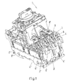
- FIG. 1 shows as an example of an inventive electrical switching device, a three-pole motor protection switch 1 with a housing 2 made of insulating material.
- the housing 2 is in the view of FIG. 1 partially removed and gives the view of the three access-side terminal contacts 4, 4 ', 4 ", which are each assigned to one of the three poles 3, 3', 3" of the motor protection switch.
- Corresponding outgoing connection contacts are located on the viewer of the FIG. 1
- Each of the connection contacts 4, 4 ', 4 " has a connection contact busbar 5 and first connection means 6, 6', 6" for the connection of at least one first external electrical conductor.
- the second electrical conductor may be a connecting conductor to an attachment or an accessory that is mechanically connected to the housing 2 of the switching device.
- the second electrical conductor is via the second connection means 8 mechanically and electrically well and firmly, and yet releasably connected to the terminal 4 and the pole 3 of the switching device 1 connected or connected.
- the second connection means 8 made of a highly electrically conductive material.
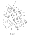
- FIG. 2 shows details of the terminal contact 4. As a central component, it has an approximately plate-shaped terminal contact busbar 5. In the viewer facing, front part of the terminal contact busbar 5, this has a rectangular recess. At an edge of this recess, the clamping spring 20 of the first connection means 6 is supported.
- the first connection means 6 corresponds to a so far known in principle plug-in spring contact.
- connection contact busbar 8 Located in the longitudinal extension direction of the terminal contact busbar behind the first connection means 6 is the second connection means 8. These are on opposite narrow sides 15, 16 of the connection contact busbar. 5 Holding bar 12, 13 attached. Each retaining bar 12, 13 is formed as a plate-shaped, on one side in a recess 17 in the narrow side 15, 16 of the terminal contact bus bar 5 mounted, aligned with its broad side 18 parallel to the longitudinal direction of the terminal contact busbar 5, beam.
- Each retaining bar 12, 13 thus depends on the terminal contact busbar 5.
- the second connection means 8 is thus lifted out of the plane of the first connection means 6, it is located above the first connection means 6. This is advantageous if, for example, the second electrical connection conductors 7 are to be inserted from above into the switching device 1 and the first connection means from the front or diagonally from the front.
- each have a resilient arm 9, 10 is attached.
- the holding bar 13 forms with the attached resilient arm 10 an L-shape.
- the resilient arms 9, 10 are formed as elongated clamping bars and arranged parallel to each other and parallel to a broad side 14 of the terminal contact busbar 5. Each resilient arm 9, 10 is thereby in a plane perpendicular to the longitudinal direction of its support beam 12, 13 resiliently pivotable.
- the rectangular cross-section of the retaining bars 12, 13 and the attachment with its broad side 18 parallel to the longitudinal direction of the terminal contact 5 has the consequence that the amount of torsional stiffness of the support bar 12, 13 in the direction of pivoting the resilient arm 9, 10 is greater than that Amount of bending stiffness in bending in the direction of the longitudinal extent of the resilient arm 9, 10th
- the two resilient arms 9, 10 thus form part of the lateral boundary of a receiving space 11 for the second external electrical conductor 7.
- the receiving space 11 has in this example a rectangular cross-section, wherein its longitudinal direction is oriented perpendicular to the longitudinal extension direction of the terminal contact busbar 5.
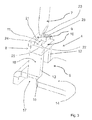
- the second electrical conductor 7 is inserted into the receiving space 11 between the two resilient arms 9, 10, see FIG. 3 ,
- the cross section of the insertion end of the second electrical conductor 7 is greater than the cross section of the receiving space.
- the peripheral contour of the introductory part of the second electrical conductor 7 wider than the distance between the two mutually facing longitudinally extended inner edges 22, 21 of the two resilient arms 9, 10, but narrower than the distance between the two mutually facing inner edges 23, 24 of the short L-legs 25, 26 forming free ends of the two retaining bars 12, 13th
- the second electrical conductor pushes apart only the two resilient arms 9, 10. Because the amount of torsional rigidity of the support beam 12, 13 in the direction of pivoting of the resilient arm 9, 10 is greater than the amount of bending stiffness in bending in the direction of the longitudinal extent of the resilient arm 9, 10 will be only the two resilient arms 9, 10th swivel against its restoring spring force and absorb the second electrical conductor between them. Due to the restoring spring force of the resilient arms 9, 10 then the insertion end of the second electrical conductor between the two resilient arms 9, 10 is clamped, thus mechanically held and electrically well connected, see FIG. 4 ,
- connection contact 4 with the connection contact busbar 5 and the second connection means 8, as described above can be produced very cheaply in one piece as a stamped bent part made of an electrically highly conductive, preferably metallic material.
- the second embodiment, in which the clamping member is formed as a hole receiver with closed circumferential contour is not shown here by figures.
Landscapes
- Physics & Mathematics (AREA)
- Electromagnetism (AREA)
- Installation Of Bus-Bars (AREA)
- Patch Boards (AREA)
Applications Claiming Priority (1)
| Application Number | Priority Date | Filing Date | Title |
|---|---|---|---|
| DE102015116085.4A DE102015116085A1 (de) | 2015-09-23 | 2015-09-23 | Elektrisches Schaltgerät |
Publications (2)
| Publication Number | Publication Date |
|---|---|
| EP3147927A1 true EP3147927A1 (fr) | 2017-03-29 |
| EP3147927B1 EP3147927B1 (fr) | 2018-08-01 |
Family
ID=56801457
Family Applications (1)
| Application Number | Title | Priority Date | Filing Date |
|---|---|---|---|
| EP16185799.0A Active EP3147927B1 (fr) | 2015-09-23 | 2016-08-26 | Commutateur electrique |
Country Status (3)
| Country | Link |
|---|---|
| EP (1) | EP3147927B1 (fr) |
| CN (1) | CN106847625B (fr) |
| DE (1) | DE102015116085A1 (fr) |
Citations (3)
| Publication number | Priority date | Publication date | Assignee | Title |
|---|---|---|---|---|
| WO1996012292A1 (fr) * | 1994-10-18 | 1996-04-25 | Bticino S.P.A. | Disjoncteur automatique miniaturise a borne multifonctionnelle et ecran de protection contre les arcs electriques internes |
| DE10236790C1 (de) * | 2002-08-10 | 2003-10-16 | Moeller Gmbh | Elektrisches Schaltgerät |
| WO2006027336A1 (fr) * | 2004-09-08 | 2006-03-16 | Siemens Aktiengesellschaft | Appareil de commutation a connexions enfichables |
Family Cites Families (1)
| Publication number | Priority date | Publication date | Assignee | Title |
|---|---|---|---|---|
| CN102037535A (zh) * | 2008-02-05 | 2011-04-27 | 西门子工业公司 | 自调整插入式接线端子 |
-
2015
- 2015-09-23 DE DE102015116085.4A patent/DE102015116085A1/de not_active Withdrawn
-
2016
- 2016-08-26 EP EP16185799.0A patent/EP3147927B1/fr active Active
- 2016-09-22 CN CN201610839883.4A patent/CN106847625B/zh active Active
Patent Citations (3)
| Publication number | Priority date | Publication date | Assignee | Title |
|---|---|---|---|---|
| WO1996012292A1 (fr) * | 1994-10-18 | 1996-04-25 | Bticino S.P.A. | Disjoncteur automatique miniaturise a borne multifonctionnelle et ecran de protection contre les arcs electriques internes |
| DE10236790C1 (de) * | 2002-08-10 | 2003-10-16 | Moeller Gmbh | Elektrisches Schaltgerät |
| WO2006027336A1 (fr) * | 2004-09-08 | 2006-03-16 | Siemens Aktiengesellschaft | Appareil de commutation a connexions enfichables |
Also Published As
| Publication number | Publication date |
|---|---|
| DE102015116085A1 (de) | 2017-03-23 |
| EP3147927B1 (fr) | 2018-08-01 |
| CN106847625B (zh) | 2020-04-24 |
| CN106847625A (zh) | 2017-06-13 |
Similar Documents
| Publication | Publication Date | Title |
|---|---|---|
| DE102008017245B4 (de) | Steckadapter für ein elektrisches Schaltgerät | |
| DE102015107853B4 (de) | Leiteranschlussklemme | |
| EP3159974B2 (fr) | Borne d'alimentation électrique | |
| DE102010014144C5 (de) | Elektrische Anschlussklemme | |
| DE102015119247B4 (de) | Verbindungsklemme | |
| EP3118938B1 (fr) | Connecteur à fiche | |
| DE202015102045U1 (de) | Federkraftklemmelement mit Schwenkhebel | |
| WO2015032516A1 (fr) | Dispositif à traversée murale | |
| EP1818964A2 (fr) | Barrette de fusibles avec contacts de sortie latéraux et module adaptateur latéral | |
| EP0221839B1 (fr) | Interrupteur de puissance comportant un boîtier isolant à ouverture frontale et une plaquette de circuit | |
| EP2419966B1 (fr) | Borne à enfichage à ressort | |
| EP2107660B1 (fr) | Connecteur de rails conducteurs | |
| EP3147927B1 (fr) | Commutateur electrique | |
| EP1990879B1 (fr) | Support de spécification destiné à la fixation d'un relais de surcharge | |
| EP2489100B1 (fr) | Borne à vis avec couvercle et appareil de coupure d'installation | |
| EP0921611B1 (fr) | Prise et interrupteur pour le secteur | |
| DE102015103113B4 (de) | Trennklemme mit konkavem Trennmesser | |
| EP3221935A1 (fr) | Dispositif de liaison électrique et procédé de production dudit dispositif de liaison électrique | |
| DE202015102561U1 (de) | Leiteranschlussklemme | |
| DE10224976B4 (de) | Verbindungsbaugruppe zum elektrischen und mechanischen Verbinden eines elektrischen Grundschaltgeräts mit einem elektrischen Zusatzschaltgerät | |
| DE102012202240A1 (de) | Klemmkörper für eine Anschlussklemme | |
| EP0141047A1 (fr) | Vis de serrage pour un domino | |
| DE102016110189B4 (de) | Verbindungsvorrichtung mit Steckklemme | |
| LU503992B1 (de) | Reihenklemme mit Ausbruchfenster | |
| EP3116067B1 (fr) | Dispositif de connexion comprenant une borne enfichable |
Legal Events
| Date | Code | Title | Description |
|---|---|---|---|
| PUAI | Public reference made under article 153(3) epc to a published international application that has entered the european phase |
Free format text: ORIGINAL CODE: 0009012 |
|
| AK | Designated contracting states |
Kind code of ref document: A1 Designated state(s): AL AT BE BG CH CY CZ DE DK EE ES FI FR GB GR HR HU IE IS IT LI LT LU LV MC MK MT NL NO PL PT RO RS SE SI SK SM TR |
|
| AX | Request for extension of the european patent |
Extension state: BA ME |
|
| 17P | Request for examination filed |
Effective date: 20170919 |
|
| GRAP | Despatch of communication of intention to grant a patent |
Free format text: ORIGINAL CODE: EPIDOSNIGR1 |
|
| INTG | Intention to grant announced |
Effective date: 20180503 |
|
| GRAS | Grant fee paid |
Free format text: ORIGINAL CODE: EPIDOSNIGR3 |
|
| GRAA | (expected) grant |
Free format text: ORIGINAL CODE: 0009210 |
|
| AK | Designated contracting states |
Kind code of ref document: B1 Designated state(s): AL AT BE BG CH CY CZ DE DK EE ES FI FR GB GR HR HU IE IS IT LI LT LU LV MC MK MT NL NO PL PT RO RS SE SI SK SM TR |
|
| REG | Reference to a national code |
Ref country code: GB Ref legal event code: FG4D Free format text: NOT ENGLISH |
|
| REG | Reference to a national code |
Ref country code: CH Ref legal event code: EP Ref country code: AT Ref legal event code: REF Ref document number: 1025299 Country of ref document: AT Kind code of ref document: T Effective date: 20180815 |
|
| REG | Reference to a national code |
Ref country code: IE Ref legal event code: FG4D Free format text: LANGUAGE OF EP DOCUMENT: GERMAN |
|
| REG | Reference to a national code |
Ref country code: DE Ref legal event code: R096 Ref document number: 502016001579 Country of ref document: DE |
|
| REG | Reference to a national code |
Ref country code: FR Ref legal event code: PLFP Year of fee payment: 3 |
|
| REG | Reference to a national code |
Ref country code: NL Ref legal event code: MP Effective date: 20180801 |
|
| REG | Reference to a national code |
Ref country code: LT Ref legal event code: MG4D |
|
| PG25 | Lapsed in a contracting state [announced via postgrant information from national office to epo] |
Ref country code: LT Free format text: LAPSE BECAUSE OF FAILURE TO SUBMIT A TRANSLATION OF THE DESCRIPTION OR TO PAY THE FEE WITHIN THE PRESCRIBED TIME-LIMIT Effective date: 20180801 Ref country code: RS Free format text: LAPSE BECAUSE OF FAILURE TO SUBMIT A TRANSLATION OF THE DESCRIPTION OR TO PAY THE FEE WITHIN THE PRESCRIBED TIME-LIMIT Effective date: 20180801 Ref country code: FI Free format text: LAPSE BECAUSE OF FAILURE TO SUBMIT A TRANSLATION OF THE DESCRIPTION OR TO PAY THE FEE WITHIN THE PRESCRIBED TIME-LIMIT Effective date: 20180801 Ref country code: SE Free format text: LAPSE BECAUSE OF FAILURE TO SUBMIT A TRANSLATION OF THE DESCRIPTION OR TO PAY THE FEE WITHIN THE PRESCRIBED TIME-LIMIT Effective date: 20180801 Ref country code: PL Free format text: LAPSE BECAUSE OF FAILURE TO SUBMIT A TRANSLATION OF THE DESCRIPTION OR TO PAY THE FEE WITHIN THE PRESCRIBED TIME-LIMIT Effective date: 20180801 Ref country code: NO Free format text: LAPSE BECAUSE OF FAILURE TO SUBMIT A TRANSLATION OF THE DESCRIPTION OR TO PAY THE FEE WITHIN THE PRESCRIBED TIME-LIMIT Effective date: 20181101 Ref country code: GR Free format text: LAPSE BECAUSE OF FAILURE TO SUBMIT A TRANSLATION OF THE DESCRIPTION OR TO PAY THE FEE WITHIN THE PRESCRIBED TIME-LIMIT Effective date: 20181102 Ref country code: NL Free format text: LAPSE BECAUSE OF FAILURE TO SUBMIT A TRANSLATION OF THE DESCRIPTION OR TO PAY THE FEE WITHIN THE PRESCRIBED TIME-LIMIT Effective date: 20180801 Ref country code: IS Free format text: LAPSE BECAUSE OF FAILURE TO SUBMIT A TRANSLATION OF THE DESCRIPTION OR TO PAY THE FEE WITHIN THE PRESCRIBED TIME-LIMIT Effective date: 20181201 Ref country code: BG Free format text: LAPSE BECAUSE OF FAILURE TO SUBMIT A TRANSLATION OF THE DESCRIPTION OR TO PAY THE FEE WITHIN THE PRESCRIBED TIME-LIMIT Effective date: 20181101 |
|
| PG25 | Lapsed in a contracting state [announced via postgrant information from national office to epo] |
Ref country code: HR Free format text: LAPSE BECAUSE OF FAILURE TO SUBMIT A TRANSLATION OF THE DESCRIPTION OR TO PAY THE FEE WITHIN THE PRESCRIBED TIME-LIMIT Effective date: 20180801 Ref country code: AL Free format text: LAPSE BECAUSE OF FAILURE TO SUBMIT A TRANSLATION OF THE DESCRIPTION OR TO PAY THE FEE WITHIN THE PRESCRIBED TIME-LIMIT Effective date: 20180801 Ref country code: LV Free format text: LAPSE BECAUSE OF FAILURE TO SUBMIT A TRANSLATION OF THE DESCRIPTION OR TO PAY THE FEE WITHIN THE PRESCRIBED TIME-LIMIT Effective date: 20180801 |
|
| PG25 | Lapsed in a contracting state [announced via postgrant information from national office to epo] |
Ref country code: IT Free format text: LAPSE BECAUSE OF FAILURE TO SUBMIT A TRANSLATION OF THE DESCRIPTION OR TO PAY THE FEE WITHIN THE PRESCRIBED TIME-LIMIT Effective date: 20180801 Ref country code: ES Free format text: LAPSE BECAUSE OF FAILURE TO SUBMIT A TRANSLATION OF THE DESCRIPTION OR TO PAY THE FEE WITHIN THE PRESCRIBED TIME-LIMIT Effective date: 20180801 Ref country code: CZ Free format text: LAPSE BECAUSE OF FAILURE TO SUBMIT A TRANSLATION OF THE DESCRIPTION OR TO PAY THE FEE WITHIN THE PRESCRIBED TIME-LIMIT Effective date: 20180801 Ref country code: RO Free format text: LAPSE BECAUSE OF FAILURE TO SUBMIT A TRANSLATION OF THE DESCRIPTION OR TO PAY THE FEE WITHIN THE PRESCRIBED TIME-LIMIT Effective date: 20180801 Ref country code: EE Free format text: LAPSE BECAUSE OF FAILURE TO SUBMIT A TRANSLATION OF THE DESCRIPTION OR TO PAY THE FEE WITHIN THE PRESCRIBED TIME-LIMIT Effective date: 20180801 Ref country code: LU Free format text: LAPSE BECAUSE OF NON-PAYMENT OF DUE FEES Effective date: 20180826 Ref country code: MC Free format text: LAPSE BECAUSE OF FAILURE TO SUBMIT A TRANSLATION OF THE DESCRIPTION OR TO PAY THE FEE WITHIN THE PRESCRIBED TIME-LIMIT Effective date: 20180801 |
|
| REG | Reference to a national code |
Ref country code: DE Ref legal event code: R097 Ref document number: 502016001579 Country of ref document: DE |
|
| REG | Reference to a national code |
Ref country code: BE Ref legal event code: MM Effective date: 20180831 |
|
| PG25 | Lapsed in a contracting state [announced via postgrant information from national office to epo] |
Ref country code: DK Free format text: LAPSE BECAUSE OF FAILURE TO SUBMIT A TRANSLATION OF THE DESCRIPTION OR TO PAY THE FEE WITHIN THE PRESCRIBED TIME-LIMIT Effective date: 20180801 Ref country code: SK Free format text: LAPSE BECAUSE OF FAILURE TO SUBMIT A TRANSLATION OF THE DESCRIPTION OR TO PAY THE FEE WITHIN THE PRESCRIBED TIME-LIMIT Effective date: 20180801 Ref country code: SM Free format text: LAPSE BECAUSE OF FAILURE TO SUBMIT A TRANSLATION OF THE DESCRIPTION OR TO PAY THE FEE WITHIN THE PRESCRIBED TIME-LIMIT Effective date: 20180801 |
|
| PLBE | No opposition filed within time limit |
Free format text: ORIGINAL CODE: 0009261 |
|
| STAA | Information on the status of an ep patent application or granted ep patent |
Free format text: STATUS: NO OPPOSITION FILED WITHIN TIME LIMIT |
|
| 26N | No opposition filed |
Effective date: 20190503 |
|
| PG25 | Lapsed in a contracting state [announced via postgrant information from national office to epo] |
Ref country code: BE Free format text: LAPSE BECAUSE OF NON-PAYMENT OF DUE FEES Effective date: 20180831 Ref country code: SI Free format text: LAPSE BECAUSE OF FAILURE TO SUBMIT A TRANSLATION OF THE DESCRIPTION OR TO PAY THE FEE WITHIN THE PRESCRIBED TIME-LIMIT Effective date: 20180801 |
|
| PG25 | Lapsed in a contracting state [announced via postgrant information from national office to epo] |
Ref country code: MT Free format text: LAPSE BECAUSE OF FAILURE TO SUBMIT A TRANSLATION OF THE DESCRIPTION OR TO PAY THE FEE WITHIN THE PRESCRIBED TIME-LIMIT Effective date: 20180801 |
|
| PG25 | Lapsed in a contracting state [announced via postgrant information from national office to epo] |
Ref country code: TR Free format text: LAPSE BECAUSE OF FAILURE TO SUBMIT A TRANSLATION OF THE DESCRIPTION OR TO PAY THE FEE WITHIN THE PRESCRIBED TIME-LIMIT Effective date: 20180801 |
|
| PG25 | Lapsed in a contracting state [announced via postgrant information from national office to epo] |
Ref country code: PT Free format text: LAPSE BECAUSE OF FAILURE TO SUBMIT A TRANSLATION OF THE DESCRIPTION OR TO PAY THE FEE WITHIN THE PRESCRIBED TIME-LIMIT Effective date: 20180801 Ref country code: LI Free format text: LAPSE BECAUSE OF NON-PAYMENT OF DUE FEES Effective date: 20190831 Ref country code: CH Free format text: LAPSE BECAUSE OF NON-PAYMENT OF DUE FEES Effective date: 20190831 |
|
| PG25 | Lapsed in a contracting state [announced via postgrant information from national office to epo] |
Ref country code: HU Free format text: LAPSE BECAUSE OF FAILURE TO SUBMIT A TRANSLATION OF THE DESCRIPTION OR TO PAY THE FEE WITHIN THE PRESCRIBED TIME-LIMIT; INVALID AB INITIO Effective date: 20160826 Ref country code: IE Free format text: LAPSE BECAUSE OF NON-PAYMENT OF DUE FEES Effective date: 20180826 Ref country code: CY Free format text: LAPSE BECAUSE OF FAILURE TO SUBMIT A TRANSLATION OF THE DESCRIPTION OR TO PAY THE FEE WITHIN THE PRESCRIBED TIME-LIMIT Effective date: 20180801 Ref country code: MK Free format text: LAPSE BECAUSE OF NON-PAYMENT OF DUE FEES Effective date: 20180801 |
|
| GBPC | Gb: european patent ceased through non-payment of renewal fee |
Effective date: 20200826 |
|
| PG25 | Lapsed in a contracting state [announced via postgrant information from national office to epo] |
Ref country code: GB Free format text: LAPSE BECAUSE OF NON-PAYMENT OF DUE FEES Effective date: 20200826 |
|
| REG | Reference to a national code |
Ref country code: AT Ref legal event code: MM01 Ref document number: 1025299 Country of ref document: AT Kind code of ref document: T Effective date: 20210826 |
|
| PG25 | Lapsed in a contracting state [announced via postgrant information from national office to epo] |
Ref country code: AT Free format text: LAPSE BECAUSE OF NON-PAYMENT OF DUE FEES Effective date: 20210826 |
|
| PGFP | Annual fee paid to national office [announced via postgrant information from national office to epo] |
Ref country code: DE Payment date: 20250820 Year of fee payment: 10 |
|
| PGFP | Annual fee paid to national office [announced via postgrant information from national office to epo] |
Ref country code: FR Payment date: 20250829 Year of fee payment: 10 |