EP3148071B1 - Elektrische servolenkvorrichtung - Google Patents
Elektrische servolenkvorrichtung Download PDFInfo
- Publication number
- EP3148071B1 EP3148071B1 EP15777852.3A EP15777852A EP3148071B1 EP 3148071 B1 EP3148071 B1 EP 3148071B1 EP 15777852 A EP15777852 A EP 15777852A EP 3148071 B1 EP3148071 B1 EP 3148071B1
- Authority
- EP
- European Patent Office
- Prior art keywords
- phase
- current
- signals
- electric power
- power steering
- Prior art date
- Legal status (The legal status is an assumption and is not a legal conclusion. Google has not performed a legal analysis and makes no representation as to the accuracy of the status listed.)
- Not-in-force
Links
- 238000001514 detection method Methods 0.000 claims description 8
- 238000000034 method Methods 0.000 description 10
- 238000010586 diagram Methods 0.000 description 6
- 229920006395 saturated elastomer Polymers 0.000 description 6
- 238000005070 sampling Methods 0.000 description 5
- 239000003990 capacitor Substances 0.000 description 3
- 230000006870 function Effects 0.000 description 3
- 101100119059 Saccharomyces cerevisiae (strain ATCC 204508 / S288c) ERG25 gene Proteins 0.000 description 2
- 238000006243 chemical reaction Methods 0.000 description 2
- 101150073536 FET3 gene Proteins 0.000 description 1
- 101150015217 FET4 gene Proteins 0.000 description 1
- 230000005540 biological transmission Effects 0.000 description 1
- 230000000694 effects Effects 0.000 description 1
- 230000008571 general function Effects 0.000 description 1
- 230000001360 synchronised effect Effects 0.000 description 1
Images


Classifications
-
- B—PERFORMING OPERATIONS; TRANSPORTING
- B62—LAND VEHICLES FOR TRAVELLING OTHERWISE THAN ON RAILS
- B62D—MOTOR VEHICLES; TRAILERS
- B62D5/00—Power-assisted or power-driven steering
- B62D5/04—Power-assisted or power-driven steering electrical, e.g. using an electric servo-motor connected to, or forming part of, the steering gear
- B62D5/0457—Power-assisted or power-driven steering electrical, e.g. using an electric servo-motor connected to, or forming part of, the steering gear characterised by control features of the drive means as such
- B62D5/046—Controlling the motor
- B62D5/0463—Controlling the motor calculating assisting torque from the motor based on driver input
-
- B—PERFORMING OPERATIONS; TRANSPORTING
- B62—LAND VEHICLES FOR TRAVELLING OTHERWISE THAN ON RAILS
- B62D—MOTOR VEHICLES; TRAILERS
- B62D5/00—Power-assisted or power-driven steering
- B62D5/04—Power-assisted or power-driven steering electrical, e.g. using an electric servo-motor connected to, or forming part of, the steering gear
- B62D5/0457—Power-assisted or power-driven steering electrical, e.g. using an electric servo-motor connected to, or forming part of, the steering gear characterised by control features of the drive means as such
- B62D5/0481—Power-assisted or power-driven steering electrical, e.g. using an electric servo-motor connected to, or forming part of, the steering gear characterised by control features of the drive means as such monitoring the steering system, e.g. failures
-
- H—ELECTRICITY
- H02—GENERATION; CONVERSION OR DISTRIBUTION OF ELECTRIC POWER
- H02P—CONTROL OR REGULATION OF ELECTRIC MOTORS, ELECTRIC GENERATORS OR DYNAMO-ELECTRIC CONVERTERS; CONTROLLING TRANSFORMERS, REACTORS OR CHOKE COILS
- H02P23/00—Arrangements or methods for the control of AC motors characterised by a control method other than vector control
- H02P23/0004—Control strategies in general, e.g. linear type, e.g. P, PI, PID, using robust control
-
- B—PERFORMING OPERATIONS; TRANSPORTING
- B62—LAND VEHICLES FOR TRAVELLING OTHERWISE THAN ON RAILS
- B62D—MOTOR VEHICLES; TRAILERS
- B62D5/00—Power-assisted or power-driven steering
- B62D5/04—Power-assisted or power-driven steering electrical, e.g. using an electric servo-motor connected to, or forming part of, the steering gear
-
- B—PERFORMING OPERATIONS; TRANSPORTING
- B62—LAND VEHICLES FOR TRAVELLING OTHERWISE THAN ON RAILS
- B62D—MOTOR VEHICLES; TRAILERS
- B62D5/00—Power-assisted or power-driven steering
- B62D5/04—Power-assisted or power-driven steering electrical, e.g. using an electric servo-motor connected to, or forming part of, the steering gear
- B62D5/0457—Power-assisted or power-driven steering electrical, e.g. using an electric servo-motor connected to, or forming part of, the steering gear characterised by control features of the drive means as such
- B62D5/046—Controlling the motor
-
- B—PERFORMING OPERATIONS; TRANSPORTING
- B62—LAND VEHICLES FOR TRAVELLING OTHERWISE THAN ON RAILS
- B62D—MOTOR VEHICLES; TRAILERS
- B62D6/00—Arrangements for automatically controlling steering depending on driving conditions sensed and responded to, e.g. control circuits
-
- G—PHYSICS
- G01—MEASURING; TESTING
- G01R—MEASURING ELECTRIC VARIABLES; MEASURING MAGNETIC VARIABLES
- G01R19/00—Arrangements for measuring currents or voltages or for indicating presence or sign thereof
- G01R19/25—Arrangements for measuring currents or voltages or for indicating presence or sign thereof using digital measurement techniques
- G01R19/2506—Arrangements for conditioning or analysing measured signals, e.g. for indicating peak values ; Details concerning sampling, digitizing or waveform capturing
- G01R19/2509—Details concerning sampling, digitizing or waveform capturing
-
- H—ELECTRICITY
- H02—GENERATION; CONVERSION OR DISTRIBUTION OF ELECTRIC POWER
- H02P—CONTROL OR REGULATION OF ELECTRIC MOTORS, ELECTRIC GENERATORS OR DYNAMO-ELECTRIC CONVERTERS; CONTROLLING TRANSFORMERS, REACTORS OR CHOKE COILS
- H02P23/00—Arrangements or methods for the control of AC motors characterised by a control method other than vector control
-
- H—ELECTRICITY
- H02—GENERATION; CONVERSION OR DISTRIBUTION OF ELECTRIC POWER
- H02P—CONTROL OR REGULATION OF ELECTRIC MOTORS, ELECTRIC GENERATORS OR DYNAMO-ELECTRIC CONVERTERS; CONTROLLING TRANSFORMERS, REACTORS OR CHOKE COILS
- H02P27/00—Arrangements or methods for the control of AC motors characterised by the kind of supply voltage
- H02P27/04—Arrangements or methods for the control of AC motors characterised by the kind of supply voltage using variable-frequency supply voltage, e.g. inverter or converter supply voltage
- H02P27/06—Arrangements or methods for the control of AC motors characterised by the kind of supply voltage using variable-frequency supply voltage, e.g. inverter or converter supply voltage using DC to AC converters or inverters
- H02P27/08—Arrangements or methods for the control of AC motors characterised by the kind of supply voltage using variable-frequency supply voltage, e.g. inverter or converter supply voltage using DC to AC converters or inverters with pulse width modulation
Definitions
- the present invention relates to an electric power steering apparatus that calculates a current command value due to at least a steering torque, performs a PWM-control of a 3-phase motor through an inverter based on the current command value, and assist-controls a steering system of a vehicle by detecting currents of the 3-phase motor and feed-backing, and in particular to an electric power steering apparatus that outside attachment circuit (s) is useless and cheap and that is capable of detecting 3-phase motor currents with a down-stream 3-shunt type of the inverter.
- An electric power steering apparatus which provides a steering mechanism of a vehicle with a steering assist torque (an assist torque) by means of a rotational torque of a motor, applies a driving force of the motor as the assist torque to a steering shaft or a rack shaft by means of a transmission mechanism such as gears or a belt through a reduction mechanism.
- EPS electric power steering apparatus
- the feedback control adjusts a voltage supplied to the motor so that a difference between a steering assist command value (a current command value) and a detected motor current value becomes small, and the adjustment of the voltage applied to the motor is generally performed by an adjustment of a duty ratio of a pulse width modulation (PWM) control.
- PWM pulse width modulation
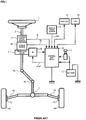
- a column shaft (a steering shaft) 2 connected to a steering wheel (a handle) 1, is connected to steered wheels 8L and 8R through reduction gears 3, universal joints 4a and 4b, a rack and pinion mechanism 5, and tie rods 6a and 6b, further via hub units 7a and 7b.
- the column shaft 2 is provided with a torque sensor 10 for detecting a steering torque Th of the steering wheel 1, and a motor 20 for assisting the steering force of the steering wheel 1 is connected to the column shaft 2 through the reduction gears 3.
- Electric power is supplied to a control unit (ECU) 30 for controlling the electric power steering apparatus from a battery 13, and an ignition key signal is inputted into the control unit 30 through an ignition key 11.
- the control unit 30 calculates a current command value of an assist (steering assist) command based on a steering torque Th detected by the torque sensor 10 and a vehicle speed Vel detected by a vehicle speed sensor 12, and controls a current supplied to the motor 20 based on a voltage control command value Vref obtained by performing compensation and so on with respect to the current command value.
- a steering angle sensor 14 is not essential and it also may be not to provide.
- a controller area network (CAN) 50 to send/receive various information and signals on the vehicle is connected to the control unit 30, and it is also possible to receive the vehicle speed Vel from the CAN. Further, a Non-CAN 51 is also possible to connect to the control unit 30, and the Non-CAN 51 sends and receives a communication, analogue/digital signals, electric wave or the like except for the CAN 50.
- CAN controller area network
- the control unit 30 mainly comprises a CPU (or an MPU or an MCU), and general functions performed by programs within the CPU are shown in FIG.2 .
- the steering torque Th detected by the torque sensor 10 and the vehicle speed Vel from the vehicle speed sensor 12 are inputted into a current command value calculating section 31 to calculate a current command value Iref1.
- the current command value calculating section 31 calculates the current command value Irefl, which is a control target value of a current to supply to the motor 20, by means of an assist map or the like based on the steering torque Th and the vehicle speed Vel.
- the calculated current command value Iref1 is inputted into a current limiting section 33 through a subtracting section 32A and a current command value Irefm of which a maximum current is limited, is inputted into a subtracting section 32B.
- the voltage control command value Vref of which the characteristic is improved is inputted into the PWM-control section 36, and further the motor 20 is PWM-driven through the inverter 37 as a driving section.
- the motor current Im is detected by a motor current detector 38 and the detected motor current Im is fed-back to the subtracting section 32B.
- the inverter 37 uses FETs as driving elements and comprises a bridge circuit of the FETs.
- a compensation signal CM from a compensating section 34 is added to the adding section 32A, which performs compensation of a system by adding the compensation signal CM and improves convergence, an inertial characteristic and so on.
- the compensating section 34 adds a self-aligning torque (SAT) 343 and the inertia 342 by an adding section 344, moreover, adds the convergence 341 to an addition result by an adding section 345, and makes the compensation signal CM of the addition result of the adding section 345.
- SAT self-aligning torque
- the PWM-control section 36 comprises a duty calculating section 36A that calculates PWM-duty command values D1 to D6 of three phases (U-phase, V-phase and W-phase) in synchronous with a PWM-carrier CS by using a predetermined expression based on the voltage control command value Vref, and a gate driving section 36B that drives respective gates of the FET1 to FET6 by the PWM-duty command values D1 to D6, compensates dead times and turns ON/OFF.
- the inverter 37 comprises a three-phase bridge (High-side FET1 to FET3 and Low-side FET4 to FET6) and drives the motor 20 by being ON/OFF-operated with the PWM-duty command values D1 to D6.
- a current detecting circuit of three-shunt type as shown in FIG. 4 is well known. That is, shunt resistances RS1 to RS3 are respectively inserted at down-stream three-phases in the inverter 37, fall voltages due to the shunt resistances RS1 to RS3 are measured, the measured voltages are respectively converted into digital values at A/D converters 37U to 37W and simultaneously converted into current values, and detected three-phase motor currents Iu to Iw are fed back.
- Patent Document 1 Japanese Published Unexamined Patent Application No. 2007-110814 A
- the above method (1) since it is necessary to provide the three A/D converters, there is a problem to become a cost-up of the MCU. Further, since the above methods (2) and (3) need the outside attachment circuit(s), it becomes a cost-up and there is a problem to insure a space for parts arrangement. Furthermore, since the above method (4) uses the A/D converter with sample-hold circuit, accuracy on A/D conversion is inferior and there are problems that a current detecting accuracy becomes low and the cost increases.
- Patent Document 1 In a current detection of the down-stream three-shunts, a method to accurately detect motor-phase currents even if PWM-duty value becomes a vicinity of 100% is disclosed in, for example, Japanese Published Unexamined Patent Application No. 2007-110814 A (Patent Document 1). However, Patent Document 1 does not disclose a current detecting method and the timing of the A/D conversion (sampling).
- the present invention has been developed in view of the above-described circumstances, and an object of the present invention is to provide an electric power steering apparatus, without outside attachment circuit(s) such as the sample-hold circuit, that is capable of simultaneously sampling two phases of which the duties are not saturated and of cheaply detecting the 3-shunt currents by using two A/D converting units in correspondence to the duty saturation phase (the maximum phase) changing when the motor is rotated.
- the present invention relates to an electric power steering apparatus that calculates a current command value due to at least a steering torque, performs a PWM-control of a 3-phase motor through an inverter based on said current command value, and assist-controls a steering system of a vehicle by detecting currents of said 3-phase motor and feed-backing
- the above-described object of the present invention is achieved by that comprising: a current detecting circuit to detect 3-phase currents of down-stream 3-shunts of said inverter; and two A/D converting units having a common channel and inputting 3-phase current detected-signals from said current detecting circuit; wherein said electric power steering apparatus includes a current detecting system that any one of said 3-phase current detected-signals is inputted into said common channel and current detected-signals of rest 2-phase are respectively inputted into other channel of said A/D converting units.
- said electric power steering apparatus further including a maximum-phase detecting section to detect a duty maximum-phase of said PWM-control and a switching section to switch inputs into said two A/D converting units of said 3-phase current detected-signals, wherein said switching section is switched based on a detection result of said maximum-phase detecting section, and two signals of said 3-phase current detected-signals corresponding to two phases except for said maximum-phase are respectively inputted into two A/D converters within said two A/D converting units and simultaneously sampled; or wherein a current of another one phase from said 2-phase current detected-signals is calculated, and motor current detected-values of three phases are outputted; or wherein said current detecting circuits respectively comprise an operational amplifier and resistance circuits to convert fall currents of down-stream shunt-resistances into current values and to output said current detected-signals; or wherein low pass filters (LPFs) are connected to respective output sections of said 3-phase current detected-
- a current detecting circuit to detect 3-phase currents of down-stream 3-shunts of an inverter; and two A/D converting units having a common channel and inputting 3-phase current detected-signals from the current detecting circuit; wherein any one of the 3-phase current detected-signals is inputted into a common channel and current detected-signals of rest 2-phase are respectively inputted into other channel of the A/D converting units. Therefore, it is possible to accurately detect the motor currents of the three phases with a cheap configuration.
- the electric power steering apparatus of the present invention without outside attachment circuit (s) such as the sample-hold circuit and in correspondence to the duty saturation phase (the maximum phase) changing when the motor is rotated, it is possible to simultaneously sample two phases except for a phase of which the duty is maximum and to cheaply detect the 3-shunt currents by using two A/D converting units.
- the present invention relates to an electric power steering apparatus that calculates a current command value due to at least a steering torque, performs a PWM-control of a 3-phase motor through an inverter based on the current command value, and assist-controls a steering system of a vehicle by detecting currents of the 3-phase motor and feed-backing.
- the electric power steering apparatus comprises a current detecting circuit to detect 3-phase currents of down-stream 3-shunts of the inverter and two A/D converting units having a common channel and inputting 3-phase current detected-signals from the current detecting circuit, and further includes a current detecting system that any one of the 3-phase current detected-signals is inputted into the common channel and current detected-signals of rest 2-phases are respectively inputted into other channel of the A/D converting units.
- a maximum-phase detecting section to detect a duty maximum-phase (High-side) of the PWM-control and a switching section to switch inputs into the two A/D converting units of the 3-phase current detected-signals.
- the switching section is switched based on a detection result of the maximum-phase detecting section, and two signals of the 3-phase current detected-signals corresponding to two phases except for the maximum-phase are inputted into two A/D converters within the two A/D converting units and simultaneously sampled.
- the current is calculated by a current calculation and it is fed back by outputting the motor current detected-signals of the three-phases.
- FIG.5 shows a configuration example of the present invention in correspondence to FIGs.3 and 4 , shunt resistances RS1 to RS3 are connected to three-phase down-stream sides in the inverter 37 and current detecting circuits are respectively connected to the shunt resistances RS1 to RS3.
- Operational amplifiers OP1, OP2, OP3 to convert fall voltages falling due to the following currents into current values and to detect, are respectively connected to two end portions of the shunt resistances RS1 to RS3 through input resistances R1 and R2, R3 and R4, R5 and R6.
- feedback resistances R10, R12, R14 are respectively connected to the operational amplifiers OP1, OP2, OP3, and balance resistances R7, R8, R9 being connected to a power source (+2.5V) are respectively connected to input terminals of the operational amplifiers OP1, OP2, OP3.
- the currents flowing the shunt resistances RS1 to RS3 are detected by calculating operations of the operational amplifiers OP1, OP2, OP3 and the connected resistances.
- Low pass filters which respectively comprise a resistance R11 and a capacitor C1, a resistance R13 and a capacitor C2 and a resistance R15 and a capacitor C3, are provided at output sections of the respective current detecting circuits, and current detected-signals Iua, Iva, Iwa outputted from the respective current detecting circuits are inputted into the MCU 100 through the respective LPFs.
- the current detected-signals Iua, Iva, Iwa removed noises are inputted into the MCU 100.
- a channel ch1 inputting the current detected-signal Iua is connected to the A/D converting unit 110
- a channel ch2 inputting the current detected-signal Iwa is connected to the A/D converting unit 120.
- the respective phase duties calculated in the duty calculating section 36A are inputted into the maximum-phase detecting section 130.
- the detail configuration of the MCU 100 is shown in FIG. 6 , and the A/D converting unit 110 comprises a switching section 111 and an A/D converter 112 and the A/D converting unit 120 does a switching section 121 and an A/D converter 122.
- the switching sections 111 and 121 are respectively switched by switching signals SWx and SWw from the maximum-phase detecting section 130.
- the motor current detected-values sampled by the A/D converters 112 and 122 are respectively inputted into the current calculating section 101, and another one-phase motor current detected-value is calculated due to the sum value of three-phase signals is "0" and is outputted.
- the 3-phase motor current detected-values Iu, Iv, Iw are outputted from the MCU 100.
- the current command value is calculated based on the steering torque and the vehicle speed (Step S1), the duties for the PWM-control are calculated described above (Step S2), and the motor 20 is driven by the inverter 37 (Step S3). Since the currents flow in the shunt resistances RS1 to RS3 being connected to the down-stream of the inverter 37 due to the driving of the motor 20 by the inverter 37, the current detected-signals Iua, Iva, Iwa are obtained in the respective current detecting circuits and are inputted into the MCU 100 (Step S4).
- the maximum-phase detecting section 130 detects the maximum-phase of the duties of the High-side FETs based on the respective duties calculated in the duty calculating section 36A (Step S5), and outputs the switching signals SWx and SWw to switch the switching sections 111 and 121 into two phases except for the duty maximum phase (Step S6). Since the duty maximum phase of the High-side FETs is a phase that an ON-time of the Low-side FETs is the minimum, the duty maximum-phase is detected and the two phases except for the duty maximum phase are simultaneously sampled (Step S7).
- the maximum-phase detecting section 130 by the switching signals SWx and SWw, inputs the V-phase current detected signal Iva into the A/D converter 112 by switching the contact of the switching section 111 into "111b" and inputs the W-phase current detected signal Iwa into the A/D converter 122 by switching the contact of the switching section 121 into "121a".
- the maximum-phase detecting section 130 since the U-phase and the W-phase except for the V-phase are simultaneously sampled when the V-phase is the duty maximum phase, the maximum-phase detecting section 130, by the switching signals SWx and SWw, inputs the U-phase current detected signal Iua into the A/D converter 112 by switching the contact of the switching section 111 into "111a” and inputs the W-phase current detected signal Iwa into the A/D converter 122 by switching the contact of the switching section 121 into "121a".
- themaximum-phase detecting section 130 since the U-phase and the V-phase except for the W-phase are simultaneously sampled when the W-phase is the duty maximum phase, themaximum-phase detecting section 130, by the switching signals SWx and SWw, inputs the U-phase current detected signal Iua into the A/D converter 112 by switching the contact of the switching section 111 into "111a” and inputs the V-phase current detected signal Iva into the A/D converter 122 by switching the contact of the switching section 121 into "121b".
- the two-phase current detected-signals except for the duty maximum phase are inputted into the two A/D converters 112 and 122 and are simultaneously A/D-converted (Step S7), and the two-phase motor current detected-values are obtained. Then, a current of another rest one-phase is calculated based on the two-phase motor current detected-values (Step s8), and the 3-phase motor current detected-values Iu, Iv, Iw are outputted from the MCU 100 (Step S9). The above operation is repeated till the judgment of the end (Step S10).
- FIG. 8 shows a sampling example of the current detection, the samplings of the two-phases, the V-phase and the W-phase, except for the U-phase which the duty of the High-side FETs is maximum are performed at a time point t1 and the motor current detected-values of the U-phase and the W-phase are obtained. At a late time point t2, the rest one-phase current is calculated in the current calculating section 101 based on the motor current detected-values of the V-phase and the W-phase.
- FIGs.8 (B) and 8 (C) show ON/OFF-state of the respective FETs of High-side and Low-side, level low side is "OFF" and level high-side is "ON".
- A/D converters and the switching sections may be physically separated or be in one unit even they have A/D converting function and switching function.
Landscapes
- Engineering & Computer Science (AREA)
- Chemical & Material Sciences (AREA)
- Combustion & Propulsion (AREA)
- Transportation (AREA)
- Mechanical Engineering (AREA)
- Power Engineering (AREA)
- Physics & Mathematics (AREA)
- General Physics & Mathematics (AREA)
- Steering Control In Accordance With Driving Conditions (AREA)
- Power Steering Mechanism (AREA)
- Control Of Ac Motors In General (AREA)
- Control Of Motors That Do Not Use Commutators (AREA)
Claims (5)
- Elektrische Servolenkvorrichtung, die einen Stromführungswert aufgrund mindestens eines Lenkdrehmoments (Th) berechnet, eine PWM-Steuerung eines 3-Phasen-Motors (20) durch einen Inverter (37) auf Grundlage des Stromführungswerts ausführt und eine Assistenz-Steuerung eines Lenksystems eines Fahrzeugs durch Erfassen von Strömen (lu, Iv, Iw) des 3-Phasen-Motors und Rückkopplung ausführt, aufweisend:eine Stromerfassungsschaltung zum Erfassen von 3-Phasen-Strömen nachgeschalteter 3-Messwiderstände (RS1, RS2, RS3) des Inverters; und zwei A/D-Wandlereinheiten (110, 120),wobei das elektrische Servolenksystem gekennzeichnet ist durch die A/D-Wandlereinheiten, die einen gemeinsamen Kanal (ch) aufweisen, unddas Eingeben von 3-Phasen-Ströme erfassender Signalen von der Stromerfassungsschaltung;wobei die elektrische Servolenkvorrichtung ein Stromerfassungssystem umfasst, wobei ein beliebiges der 3-Phasen-Ströme erfassenden Signale in den gemeinsamen Kanal eingegeben wird und stromerfassende Signale von verbleibenden 2-Phasen entsprechend in einen anderen Kanal (ch1, ch2) der A/D-Wandlereinheiten (110, 120) eingegeben werden.
- Elektrische Servolenkvorrichtung nach Anspruch 1, wobei die elektrische Servolenkvorrichtung ferner einen Maximalphasenerfassungsabschnitt zum Erfassen einer tastverhältnismäßig maximalen Phase der PWM-Steuerung und einen Schaltabschnitt zum Schalten von Eingaben in die zwei A/D-Wandlereinheiten der 3-phasenstromerfassenden Signale umfasst,
wobei der Schaltabschnitt auf Grundlage eines Erfassungsergebnisses des Maximalphasenerfassungsabschnitts geschaltet wird und zwei Signale der 3-Phasen-Ströme erfassenden Signale, die zwei Phasen außer der Maximalphase entsprechen, entsprechend in die zwei A/D-Wandler in den zwei A/D-Wandlereinheiten eingegeben und simultan abgetastet werden. - Elektrische Servolenkvorrichtung nach Anspruch 1 oder 2,
wobei ein Strom einer anderen Phase von den 2-Phasen-Ströme erfassenden Signalen berechnet wird und motorstromerfassende Werte von drei Phasen ausgegeben werden. - Elektrische Servolenkvorrichtung nach einem der Ansprüche 1 bis 3,
wobei die Stromerfassungsschaltungen einen Operationsverstärker und Widerstandsschaltungen zum entsprechenden Wandeln von stromabhängigen Abfällen nachgeschalteter Messwiderstände in Stromwerte und Ausgeben der stromerfassenden Signale aufweisen. - Elektrische Servolenkvorrichtung nach einem der Ansprüche 1 bis 4, wobei Tiefpassfilter (LPF) mit entsprechenden Ausgabeabschnitten der 3-phasenstromerfassenden Signale verbunden sind.
Applications Claiming Priority (2)
| Application Number | Priority Date | Filing Date | Title |
|---|---|---|---|
| JP2014111230 | 2014-05-29 | ||
| PCT/JP2015/061956 WO2015182287A1 (ja) | 2014-05-29 | 2015-04-20 | 電動パワーステアリング装置 |
Publications (3)
| Publication Number | Publication Date |
|---|---|
| EP3148071A1 EP3148071A1 (de) | 2017-03-29 |
| EP3148071A4 EP3148071A4 (de) | 2017-10-11 |
| EP3148071B1 true EP3148071B1 (de) | 2018-10-03 |
Family
ID=54698628
Family Applications (1)
| Application Number | Title | Priority Date | Filing Date |
|---|---|---|---|
| EP15777852.3A Not-in-force EP3148071B1 (de) | 2014-05-29 | 2015-04-20 | Elektrische servolenkvorrichtung |
Country Status (5)
| Country | Link |
|---|---|
| US (1) | US9707993B2 (de) |
| EP (1) | EP3148071B1 (de) |
| JP (1) | JP5858207B1 (de) |
| CN (1) | CN105358410B (de) |
| WO (1) | WO2015182287A1 (de) |
Families Citing this family (6)
| Publication number | Priority date | Publication date | Assignee | Title |
|---|---|---|---|---|
| JP2017135835A (ja) * | 2016-01-27 | 2017-08-03 | 富士電機株式会社 | 電流検出装置 |
| CN106771480A (zh) * | 2016-11-30 | 2017-05-31 | 旋智电子科技(上海)有限公司 | 感应电流检测系统、感应电流检测方法及逆变器驱动装置 |
| DE102017215281A1 (de) * | 2017-08-31 | 2019-02-28 | Continental Automotive Gmbh | Verfahren zum Ermitteln der Stromwerte in einem Dreiphasensystem |
| WO2019049284A1 (ja) * | 2017-09-07 | 2019-03-14 | 日本精工株式会社 | モータ制御装置及びそれを搭載した電動パワーステアリング装置 |
| DE102019100638B4 (de) * | 2019-01-11 | 2024-04-25 | Tdk-Micronas Gmbh | Strommesssystem für einen kommutierten Motor |
| CN114142772A (zh) * | 2021-11-15 | 2022-03-04 | 沈阳工程学院 | 巡检控制功率检测电路 |
Family Cites Families (20)
| Publication number | Priority date | Publication date | Assignee | Title |
|---|---|---|---|---|
| JPH08119124A (ja) * | 1994-10-20 | 1996-05-14 | Koyo Seiko Co Ltd | 電動パワーステアリング装置 |
| TW584688B (en) * | 2001-06-06 | 2004-04-21 | Toshiba Corp | Washing machine |
| JP4455075B2 (ja) * | 2004-01-28 | 2010-04-21 | 三菱電機株式会社 | モータ制御装置 |
| JP4422567B2 (ja) * | 2004-06-30 | 2010-02-24 | 株式会社日立製作所 | モータ駆動装置,電動アクチュエータおよび電動パワーステアリング装置 |
| JP4742797B2 (ja) * | 2005-10-12 | 2011-08-10 | 日本精工株式会社 | モータ駆動制御装置及びそれを用いた電動パワーステアリング装置の制御装置 |
| JP5131432B2 (ja) * | 2007-02-08 | 2013-01-30 | 株式会社ジェイテクト | モータ用制御装置 |
| JP5191152B2 (ja) * | 2007-03-23 | 2013-04-24 | 三菱電機株式会社 | モータ駆動装置 |
| JP4637148B2 (ja) * | 2007-08-27 | 2011-02-23 | 株式会社日立製作所 | 電力変換装置 |
| US7834574B2 (en) * | 2007-11-26 | 2010-11-16 | Gm Global Technology Operations, Inc. | Phase current sampling and regulating apparatus and methods, and electric motor drive systems |
| KR20130086075A (ko) * | 2008-03-31 | 2013-07-30 | 미쓰비시덴키 가부시키가이샤 | 모터 구동 제어 장치 |
| JP2009247181A (ja) * | 2008-03-31 | 2009-10-22 | Jtekt Corp | モータ制御装置および電動パワーステアリング装置 |
| JP5428688B2 (ja) * | 2009-09-14 | 2014-02-26 | 株式会社ジェイテクト | モータ制御装置及び電動パワーステアリング装置 |
| JP5724776B2 (ja) * | 2011-09-12 | 2015-05-27 | 日本精工株式会社 | モータ制御装置及び電動パワーステアリング装置 |
| JP5652434B2 (ja) * | 2012-06-15 | 2015-01-14 | 株式会社デンソー | モータ制御装置、及び、これを用いた電動パワーステアリング装置 |
| JP5945741B2 (ja) * | 2012-09-24 | 2016-07-05 | 日立オートモティブシステムズ株式会社 | 電動パワーステアリング装置 |
| JP5968805B2 (ja) * | 2013-02-28 | 2016-08-10 | 日立オートモティブシステムズ株式会社 | モータ装置およびモータ駆動装置 |
| CN104871425B (zh) * | 2013-04-17 | 2017-07-11 | 日本精工株式会社 | 多相电动机控制装置及使用该多相电动机控制装置的电动助力转向装置 |
| JP5839011B2 (ja) * | 2013-09-18 | 2016-01-06 | 株式会社デンソー | 電力変換装置、および、これを用いた電動パワーステアリング装置 |
| JP5920300B2 (ja) * | 2013-09-18 | 2016-05-18 | 株式会社デンソー | 電力変換装置、および、これを用いた電動パワーステアリング装置 |
| JP5892394B2 (ja) * | 2014-01-28 | 2016-03-23 | 株式会社デンソー | 電力変換装置、および、これを用いた電動パワーステアリング装置 |
-
2015
- 2015-04-20 EP EP15777852.3A patent/EP3148071B1/de not_active Not-in-force
- 2015-04-20 JP JP2015543165A patent/JP5858207B1/ja not_active Expired - Fee Related
- 2015-04-20 WO PCT/JP2015/061956 patent/WO2015182287A1/ja not_active Ceased
- 2015-04-20 CN CN201580000549.3A patent/CN105358410B/zh not_active Expired - Fee Related
- 2015-04-20 US US14/782,089 patent/US9707993B2/en not_active Expired - Fee Related
Non-Patent Citations (1)
| Title |
|---|
| None * |
Also Published As
| Publication number | Publication date |
|---|---|
| JP5858207B1 (ja) | 2016-02-10 |
| US9707993B2 (en) | 2017-07-18 |
| WO2015182287A1 (ja) | 2015-12-03 |
| EP3148071A1 (de) | 2017-03-29 |
| JPWO2015182287A1 (ja) | 2017-04-20 |
| US20170072995A1 (en) | 2017-03-16 |
| CN105358410A (zh) | 2016-02-24 |
| CN105358410B (zh) | 2017-05-24 |
| EP3148071A4 (de) | 2017-10-11 |
Similar Documents
| Publication | Publication Date | Title |
|---|---|---|
| EP3148071B1 (de) | Elektrische servolenkvorrichtung | |
| EP3020615B1 (de) | Elektrische servolenkvorrichtung | |
| EP2945277B1 (de) | Steuerungsvorrichtung für mehrphasenmotor und elektrische servolenkvorrichtung damit | |
| US9050996B2 (en) | Control device for electric power steering apparatus | |
| CN109463039B (zh) | 电动助力转向装置 | |
| EP1526060B1 (de) | Servolenksystem | |
| CN103155401B (zh) | 电动机控制装置及电动助力转向装置 | |
| US10286949B2 (en) | Electric power steering apparatus | |
| EP2410652A1 (de) | Motorsteuerungsvorrichtung und elektrische servolenkvorrichtung | |
| EP2299587A2 (de) | Motorantriebsvorrichtung geeignet, einen Fehlerzustand zu erkennen | |
| EP3255781B1 (de) | Motorsteuerungsvorrichtung und elektrische servolenkung damit | |
| EP1722469A1 (de) | Steuereinrichtung für eine motorgetriebene servolenkeinrichtung | |
| EP3197041B1 (de) | Motorsteuerungsvorrichtung und elektrische servolenkvorrichtung damit | |
| JP4350077B2 (ja) | インバータ装置、モータ装置、伝達比可変装置、および操舵補助装置 | |
| JP5392025B2 (ja) | モータ制御装置及びそれを用いた電動パワーステアリング装置 | |
| JP4967767B2 (ja) | 電動パワーステアリング制御装置 | |
| JP2007325409A (ja) | モータ制御装置 | |
| JP2016120913A (ja) | 電動パワーステアリング装置 | |
| JP2005160221A (ja) | 電動パワーステアリング装置の制御装置 | |
| JP4461917B2 (ja) | 電流検出装置及びモータ制御装置 | |
| KR20150062304A (ko) | 전자식 조향 장치 및 이를 이용한 모터 전류 제어 방법 |
Legal Events
| Date | Code | Title | Description |
|---|---|---|---|
| STAA | Information on the status of an ep patent application or granted ep patent |
Free format text: STATUS: THE INTERNATIONAL PUBLICATION HAS BEEN MADE |
|
| PUAI | Public reference made under article 153(3) epc to a published international application that has entered the european phase |
Free format text: ORIGINAL CODE: 0009012 |
|
| STAA | Information on the status of an ep patent application or granted ep patent |
Free format text: STATUS: REQUEST FOR EXAMINATION WAS MADE |
|
| 17P | Request for examination filed |
Effective date: 20151019 |
|
| AK | Designated contracting states |
Kind code of ref document: A1 Designated state(s): AL AT BE BG CH CY CZ DE DK EE ES FI FR GB GR HR HU IE IS IT LI LT LU LV MC MK MT NL NO PL PT RO RS SE SI SK SM TR |
|
| AX | Request for extension of the european patent |
Extension state: BA ME |
|
| R17P | Request for examination filed (corrected) |
Effective date: 20151019 |
|
| R17P | Request for examination filed (corrected) |
Effective date: 20151019 |
|
| DAV | Request for validation of the european patent (deleted) | ||
| DAX | Request for extension of the european patent (deleted) | ||
| A4 | Supplementary search report drawn up and despatched |
Effective date: 20170907 |
|
| RIC1 | Information provided on ipc code assigned before grant |
Ipc: B62D 119/00 20060101ALI20170901BHEP Ipc: B62D 5/04 20060101ALI20170901BHEP Ipc: H02P 23/00 20160101AFI20170901BHEP Ipc: B62D 113/00 20060101ALI20170901BHEP Ipc: B62D 101/00 20060101ALI20170901BHEP Ipc: B62D 6/00 20060101ALI20170901BHEP |
|
| GRAP | Despatch of communication of intention to grant a patent |
Free format text: ORIGINAL CODE: EPIDOSNIGR1 |
|
| STAA | Information on the status of an ep patent application or granted ep patent |
Free format text: STATUS: GRANT OF PATENT IS INTENDED |
|
| INTG | Intention to grant announced |
Effective date: 20180426 |
|
| GRAS | Grant fee paid |
Free format text: ORIGINAL CODE: EPIDOSNIGR3 |
|
| GRAA | (expected) grant |
Free format text: ORIGINAL CODE: 0009210 |
|
| STAA | Information on the status of an ep patent application or granted ep patent |
Free format text: STATUS: THE PATENT HAS BEEN GRANTED |
|
| AK | Designated contracting states |
Kind code of ref document: B1 Designated state(s): AL AT BE BG CH CY CZ DE DK EE ES FI FR GB GR HR HU IE IS IT LI LT LU LV MC MK MT NL NO PL PT RO RS SE SI SK SM TR |
|
| REG | Reference to a national code |
Ref country code: GB Ref legal event code: FG4D |
|
| REG | Reference to a national code |
Ref country code: CH Ref legal event code: EP Ref country code: AT Ref legal event code: REF Ref document number: 1049715 Country of ref document: AT Kind code of ref document: T Effective date: 20181015 |
|
| REG | Reference to a national code |
Ref country code: IE Ref legal event code: FG4D Ref country code: DE Ref legal event code: R096 Ref document number: 602015017583 Country of ref document: DE |
|
| REG | Reference to a national code |
Ref country code: NL Ref legal event code: MP Effective date: 20181003 |
|
| REG | Reference to a national code |
Ref country code: LT Ref legal event code: MG4D |
|
| REG | Reference to a national code |
Ref country code: AT Ref legal event code: MK05 Ref document number: 1049715 Country of ref document: AT Kind code of ref document: T Effective date: 20181003 |
|
| PG25 | Lapsed in a contracting state [announced via postgrant information from national office to epo] |
Ref country code: NL Free format text: LAPSE BECAUSE OF FAILURE TO SUBMIT A TRANSLATION OF THE DESCRIPTION OR TO PAY THE FEE WITHIN THE PRESCRIBED TIME-LIMIT Effective date: 20181003 |
|
| PG25 | Lapsed in a contracting state [announced via postgrant information from national office to epo] |
Ref country code: LV Free format text: LAPSE BECAUSE OF FAILURE TO SUBMIT A TRANSLATION OF THE DESCRIPTION OR TO PAY THE FEE WITHIN THE PRESCRIBED TIME-LIMIT Effective date: 20181003 Ref country code: PL Free format text: LAPSE BECAUSE OF FAILURE TO SUBMIT A TRANSLATION OF THE DESCRIPTION OR TO PAY THE FEE WITHIN THE PRESCRIBED TIME-LIMIT Effective date: 20181003 Ref country code: HR Free format text: LAPSE BECAUSE OF FAILURE TO SUBMIT A TRANSLATION OF THE DESCRIPTION OR TO PAY THE FEE WITHIN THE PRESCRIBED TIME-LIMIT Effective date: 20181003 Ref country code: AT Free format text: LAPSE BECAUSE OF FAILURE TO SUBMIT A TRANSLATION OF THE DESCRIPTION OR TO PAY THE FEE WITHIN THE PRESCRIBED TIME-LIMIT Effective date: 20181003 Ref country code: BG Free format text: LAPSE BECAUSE OF FAILURE TO SUBMIT A TRANSLATION OF THE DESCRIPTION OR TO PAY THE FEE WITHIN THE PRESCRIBED TIME-LIMIT Effective date: 20190103 Ref country code: ES Free format text: LAPSE BECAUSE OF FAILURE TO SUBMIT A TRANSLATION OF THE DESCRIPTION OR TO PAY THE FEE WITHIN THE PRESCRIBED TIME-LIMIT Effective date: 20181003 Ref country code: NO Free format text: LAPSE BECAUSE OF FAILURE TO SUBMIT A TRANSLATION OF THE DESCRIPTION OR TO PAY THE FEE WITHIN THE PRESCRIBED TIME-LIMIT Effective date: 20190103 Ref country code: IS Free format text: LAPSE BECAUSE OF FAILURE TO SUBMIT A TRANSLATION OF THE DESCRIPTION OR TO PAY THE FEE WITHIN THE PRESCRIBED TIME-LIMIT Effective date: 20190203 Ref country code: LT Free format text: LAPSE BECAUSE OF FAILURE TO SUBMIT A TRANSLATION OF THE DESCRIPTION OR TO PAY THE FEE WITHIN THE PRESCRIBED TIME-LIMIT Effective date: 20181003 Ref country code: CZ Free format text: LAPSE BECAUSE OF FAILURE TO SUBMIT A TRANSLATION OF THE DESCRIPTION OR TO PAY THE FEE WITHIN THE PRESCRIBED TIME-LIMIT Effective date: 20181003 Ref country code: FI Free format text: LAPSE BECAUSE OF FAILURE TO SUBMIT A TRANSLATION OF THE DESCRIPTION OR TO PAY THE FEE WITHIN THE PRESCRIBED TIME-LIMIT Effective date: 20181003 |
|
| PG25 | Lapsed in a contracting state [announced via postgrant information from national office to epo] |
Ref country code: GR Free format text: LAPSE BECAUSE OF FAILURE TO SUBMIT A TRANSLATION OF THE DESCRIPTION OR TO PAY THE FEE WITHIN THE PRESCRIBED TIME-LIMIT Effective date: 20190104 Ref country code: SE Free format text: LAPSE BECAUSE OF FAILURE TO SUBMIT A TRANSLATION OF THE DESCRIPTION OR TO PAY THE FEE WITHIN THE PRESCRIBED TIME-LIMIT Effective date: 20181003 Ref country code: RS Free format text: LAPSE BECAUSE OF FAILURE TO SUBMIT A TRANSLATION OF THE DESCRIPTION OR TO PAY THE FEE WITHIN THE PRESCRIBED TIME-LIMIT Effective date: 20181003 Ref country code: AL Free format text: LAPSE BECAUSE OF FAILURE TO SUBMIT A TRANSLATION OF THE DESCRIPTION OR TO PAY THE FEE WITHIN THE PRESCRIBED TIME-LIMIT Effective date: 20181003 Ref country code: PT Free format text: LAPSE BECAUSE OF FAILURE TO SUBMIT A TRANSLATION OF THE DESCRIPTION OR TO PAY THE FEE WITHIN THE PRESCRIBED TIME-LIMIT Effective date: 20190203 |
|
| REG | Reference to a national code |
Ref country code: DE Ref legal event code: R097 Ref document number: 602015017583 Country of ref document: DE |
|
| PG25 | Lapsed in a contracting state [announced via postgrant information from national office to epo] |
Ref country code: DK Free format text: LAPSE BECAUSE OF FAILURE TO SUBMIT A TRANSLATION OF THE DESCRIPTION OR TO PAY THE FEE WITHIN THE PRESCRIBED TIME-LIMIT Effective date: 20181003 Ref country code: IT Free format text: LAPSE BECAUSE OF FAILURE TO SUBMIT A TRANSLATION OF THE DESCRIPTION OR TO PAY THE FEE WITHIN THE PRESCRIBED TIME-LIMIT Effective date: 20181003 |
|
| PLBE | No opposition filed within time limit |
Free format text: ORIGINAL CODE: 0009261 |
|
| STAA | Information on the status of an ep patent application or granted ep patent |
Free format text: STATUS: NO OPPOSITION FILED WITHIN TIME LIMIT |
|
| PG25 | Lapsed in a contracting state [announced via postgrant information from national office to epo] |
Ref country code: RO Free format text: LAPSE BECAUSE OF FAILURE TO SUBMIT A TRANSLATION OF THE DESCRIPTION OR TO PAY THE FEE WITHIN THE PRESCRIBED TIME-LIMIT Effective date: 20181003 Ref country code: EE Free format text: LAPSE BECAUSE OF FAILURE TO SUBMIT A TRANSLATION OF THE DESCRIPTION OR TO PAY THE FEE WITHIN THE PRESCRIBED TIME-LIMIT Effective date: 20181003 Ref country code: SM Free format text: LAPSE BECAUSE OF FAILURE TO SUBMIT A TRANSLATION OF THE DESCRIPTION OR TO PAY THE FEE WITHIN THE PRESCRIBED TIME-LIMIT Effective date: 20181003 Ref country code: SK Free format text: LAPSE BECAUSE OF FAILURE TO SUBMIT A TRANSLATION OF THE DESCRIPTION OR TO PAY THE FEE WITHIN THE PRESCRIBED TIME-LIMIT Effective date: 20181003 |
|
| 26N | No opposition filed |
Effective date: 20190704 |
|
| PG25 | Lapsed in a contracting state [announced via postgrant information from national office to epo] |
Ref country code: SI Free format text: LAPSE BECAUSE OF FAILURE TO SUBMIT A TRANSLATION OF THE DESCRIPTION OR TO PAY THE FEE WITHIN THE PRESCRIBED TIME-LIMIT Effective date: 20181003 |
|
| REG | Reference to a national code |
Ref country code: CH Ref legal event code: PL |
|
| REG | Reference to a national code |
Ref country code: BE Ref legal event code: MM Effective date: 20190430 |
|
| PG25 | Lapsed in a contracting state [announced via postgrant information from national office to epo] |
Ref country code: LU Free format text: LAPSE BECAUSE OF NON-PAYMENT OF DUE FEES Effective date: 20190420 Ref country code: MC Free format text: LAPSE BECAUSE OF FAILURE TO SUBMIT A TRANSLATION OF THE DESCRIPTION OR TO PAY THE FEE WITHIN THE PRESCRIBED TIME-LIMIT Effective date: 20181003 |
|
| PG25 | Lapsed in a contracting state [announced via postgrant information from national office to epo] |
Ref country code: CH Free format text: LAPSE BECAUSE OF NON-PAYMENT OF DUE FEES Effective date: 20190430 Ref country code: LI Free format text: LAPSE BECAUSE OF NON-PAYMENT OF DUE FEES Effective date: 20190430 |
|
| PG25 | Lapsed in a contracting state [announced via postgrant information from national office to epo] |
Ref country code: BE Free format text: LAPSE BECAUSE OF NON-PAYMENT OF DUE FEES Effective date: 20190430 |
|
| PG25 | Lapsed in a contracting state [announced via postgrant information from national office to epo] |
Ref country code: TR Free format text: LAPSE BECAUSE OF FAILURE TO SUBMIT A TRANSLATION OF THE DESCRIPTION OR TO PAY THE FEE WITHIN THE PRESCRIBED TIME-LIMIT Effective date: 20181003 |
|
| PG25 | Lapsed in a contracting state [announced via postgrant information from national office to epo] |
Ref country code: IE Free format text: LAPSE BECAUSE OF NON-PAYMENT OF DUE FEES Effective date: 20190420 |
|
| PGFP | Annual fee paid to national office [announced via postgrant information from national office to epo] |
Ref country code: FR Payment date: 20200312 Year of fee payment: 6 |
|
| PGFP | Annual fee paid to national office [announced via postgrant information from national office to epo] |
Ref country code: DE Payment date: 20200408 Year of fee payment: 6 |
|
| PGFP | Annual fee paid to national office [announced via postgrant information from national office to epo] |
Ref country code: GB Payment date: 20200408 Year of fee payment: 6 |
|
| PG25 | Lapsed in a contracting state [announced via postgrant information from national office to epo] |
Ref country code: CY Free format text: LAPSE BECAUSE OF FAILURE TO SUBMIT A TRANSLATION OF THE DESCRIPTION OR TO PAY THE FEE WITHIN THE PRESCRIBED TIME-LIMIT Effective date: 20181003 |
|
| PG25 | Lapsed in a contracting state [announced via postgrant information from national office to epo] |
Ref country code: MT Free format text: LAPSE BECAUSE OF FAILURE TO SUBMIT A TRANSLATION OF THE DESCRIPTION OR TO PAY THE FEE WITHIN THE PRESCRIBED TIME-LIMIT Effective date: 20181003 Ref country code: HU Free format text: LAPSE BECAUSE OF FAILURE TO SUBMIT A TRANSLATION OF THE DESCRIPTION OR TO PAY THE FEE WITHIN THE PRESCRIBED TIME-LIMIT; INVALID AB INITIO Effective date: 20150420 |
|
| REG | Reference to a national code |
Ref country code: DE Ref legal event code: R119 Ref document number: 602015017583 Country of ref document: DE |
|
| GBPC | Gb: european patent ceased through non-payment of renewal fee |
Effective date: 20210420 |
|
| PG25 | Lapsed in a contracting state [announced via postgrant information from national office to epo] |
Ref country code: DE Free format text: LAPSE BECAUSE OF NON-PAYMENT OF DUE FEES Effective date: 20211103 Ref country code: FR Free format text: LAPSE BECAUSE OF NON-PAYMENT OF DUE FEES Effective date: 20210430 Ref country code: GB Free format text: LAPSE BECAUSE OF NON-PAYMENT OF DUE FEES Effective date: 20210420 |
|
| PG25 | Lapsed in a contracting state [announced via postgrant information from national office to epo] |
Ref country code: MK Free format text: LAPSE BECAUSE OF FAILURE TO SUBMIT A TRANSLATION OF THE DESCRIPTION OR TO PAY THE FEE WITHIN THE PRESCRIBED TIME-LIMIT Effective date: 20181003 |