EP3148464B1 - Vorrichtung zur biologischen dekontamination von perkutanen zugängen und verfahren hierzu - Google Patents
Vorrichtung zur biologischen dekontamination von perkutanen zugängen und verfahren hierzu Download PDFInfo
- Publication number
- EP3148464B1 EP3148464B1 EP15729767.2A EP15729767A EP3148464B1 EP 3148464 B1 EP3148464 B1 EP 3148464B1 EP 15729767 A EP15729767 A EP 15729767A EP 3148464 B1 EP3148464 B1 EP 3148464B1
- Authority
- EP
- European Patent Office
- Prior art keywords
- treatment surface
- stomata
- percutaneous access
- plasma
- percutaneous
- Prior art date
- Legal status (The legal status is an assumption and is not a legal conclusion. Google has not performed a legal analysis and makes no representation as to the accuracy of the status listed.)
- Active
Links
Images


Classifications
-
- A—HUMAN NECESSITIES
- A61—MEDICAL OR VETERINARY SCIENCE; HYGIENE
- A61N—ELECTROTHERAPY; MAGNETOTHERAPY; RADIATION THERAPY; ULTRASOUND THERAPY
- A61N1/00—Electrotherapy; Circuits therefor
- A61N1/44—Applying ionised fluids
-
- A—HUMAN NECESSITIES
- A61—MEDICAL OR VETERINARY SCIENCE; HYGIENE
- A61B—DIAGNOSIS; SURGERY; IDENTIFICATION
- A61B18/00—Surgical instruments, devices or methods for transferring non-mechanical forms of energy to or from the body
- A61B18/04—Surgical instruments, devices or methods for transferring non-mechanical forms of energy to or from the body by heating
- A61B18/042—Surgical instruments, devices or methods for transferring non-mechanical forms of energy to or from the body by heating using additional gas becoming plasma
-
- H—ELECTRICITY
- H05—ELECTRIC TECHNIQUES NOT OTHERWISE PROVIDED FOR
- H05H—PLASMA TECHNIQUE; PRODUCTION OF ACCELERATED ELECTRICALLY-CHARGED PARTICLES OR OF NEUTRONS; PRODUCTION OR ACCELERATION OF NEUTRAL MOLECULAR OR ATOMIC BEAMS
- H05H1/00—Generating plasma; Handling plasma
- H05H1/24—Generating plasma
- H05H1/2406—Generating plasma using dielectric barrier discharges, i.e. with a dielectric interposed between the electrodes
-
- H—ELECTRICITY
- H05—ELECTRIC TECHNIQUES NOT OTHERWISE PROVIDED FOR
- H05H—PLASMA TECHNIQUE; PRODUCTION OF ACCELERATED ELECTRICALLY-CHARGED PARTICLES OR OF NEUTRONS; PRODUCTION OR ACCELERATION OF NEUTRAL MOLECULAR OR ATOMIC BEAMS
- H05H1/00—Generating plasma; Handling plasma
- H05H1/24—Generating plasma
- H05H1/2406—Generating plasma using dielectric barrier discharges, i.e. with a dielectric interposed between the electrodes
- H05H1/2431—Generating plasma using dielectric barrier discharges, i.e. with a dielectric interposed between the electrodes using cylindrical electrodes, e.g. rotary drums
Definitions
- the invention relates to a device for the biological decontamination of percutaneous accesses or stomata of patients with a plasma generator for generating a decontaminating plasma adjacent to a treatment surface of the plasma generator.
- percutaneous through the skin
- catheters of all types e.g. bladder catheters, ureteral catheters, port catheters, tube catheters, cardiac catheters, dialysis catheters, etc.
- various types of external drainage e.g. Redon drainage, capillary drainage, Shirley drainage, T -Drainage, pancreatic drainage, etc.
- body fluids such as blood, tissue fluid, wound secretions and pus, which can arise in particular after surgical interventions, from the inside of the body to the outside.
- Stomata are z. B. to divert the contents of hollow organs to the outside (enterostoma, colostoma, ileostoma, urostoma, tracheostoma, gastrostroma), such as in the case of an artificial bowel movement (enterostoma) or an artificial urinary diversion (urostoma), etc., for the implantation of endo-exo-prostheses, in which, after amputation of the extremities, a bone-anchored "endostalk" is passed through the skin to mount an external "exo-prosthesis", or to relocate Percutaneous control cables (drivelines), such as those used, for example, to connect an implanted ventricular assist device (VAD - ventricular assist device: a type of "artificial heart”) to the external control device, are necessary.
- VAD - ventricular assist device a type of "artificial heart
- a problem with the application of such accesses and stomata is the risk of infection in the skin area concerned.
- the risk of infection in this area is particularly high because, on the one hand, the skin, as the largest body organ, basically offers a large target area for germs and, on the other hand, skin germs through the catheter or drainage Entry points into the body, where they can cause complications such as abscess formation or life-threatening sepsis (blood poisoning). Therefore, avoiding or reducing the risk of infection when relocating aftercare for percutaneous accesses and stomata of any kind plays an important role.
- the skin areas surrounding a percutaneous access or a stoma are covered with a dry, sterile bandage, regularly inspected, cleaned and treated with antiseptics and, if necessary, treated prophylactically with antibiotics.
- special protective measures such as decolonization of the skin, may also be necessary, e.g. if the skin is colonized with multi-resistant pathogens.
- the residual risk of infections is high in the case of percutaneous accesses and stomata, so that a further reduction of the risk should be aimed for.
- the use of disinfectants poses the problem of possible allergic reactions.
- the disinfection measures are usually time-consuming and material-intensive. This is especially true in the case of prophylactic measures against infection by multi-resistant pathogens.
- measures to promote healing are also required to promote wound healing.
- WO 2011/023478 A1 discloses a device for the flat treatment of areas of human or animal skin or mucous membrane surfaces by means of a cold atmospheric pressure plasma.
- a cuff with an electrode arrangement built into the cuff is wound around a part of the body. The area to be treated is completely covered by the cuff.
- WO 2013/167693 A1 a device for the plasma treatment of human, animal or plant surfaces, in particular skin or slime areas, is known.
- the device has an electrode arrangement in which the high-voltage electrode consists of a thin wire and is coated with an insulating layer.
- the grounded electrode consists of a gas-permeable, textile surface structure that can be flexibly placed on any curved surface.
- a device according to the preamble of claim 1 is off DE202009011521 known.
- the object of the present invention is to create a device for the biological decontamination of percutaneous accesses or stomata from the patient.
- decontaminating plasma for the biological decontamination of percutaneous accesses or stomata is therefore proposed in order to make infection prophylaxis easier and more effective and also to promote wound healing.
- a device for biological decontamination of the percutaneous access or stomata of patients has a plasma generator with a treatment area that provides a decontaminating plasma, this treatment area at least partially encompassing a percutaneous access or stomata adapting when curved and to the percutaneous access or Stomata can be created.
- the treatment surface of a plasma generator at least partially encompassing a percutaneous access or stomata and by applying this adaptably curved treatment surface to the percutaneous access or stomata makes it possible to reduce the risk of infection through percutaneous accesses or stomata in a reliable and simple manner.
- the plasma generator can preferably be designed to generate a cold atmospheric pressure plasma on the treatment surface.
- the device enables the risk of infection to be significantly minimized in the area of percutaneous accesses and stomata.
- allergic reactions are avoided, as they otherwise often occur when disinfecting percutaneous accesses and stomata with infectious agents.
- infections caused by multi-resistant pathogens can be effectively avoided with comparatively little expenditure of time and material.
- the device enables considerable time and material savings when using percutaneous accesses or stomata compared to conventional infection prevention.
- the device promotes wound healing As a result, the plasma used for decontamination not only has a decontaminating, but also healing that promotes wound healing.
- a tubular percutaneous access or a tubular stomata has a treatment surface integrally connected thereto on the outside of a flexible tube used for introducing or discharging fluid.
- a plasma treatment of the tissue area adjoining the treatment area can take place permanently or without additional installation work.
- the device is thus a percutaneous access or a stomata with a tubular structure which has a plasma treatment surface which is curved adaptably to the tubular structure and which at least partially surrounds this tubular structure.
- the treatment surface is cylindrical and the interior of the cylindrical treatment surface is provided for receiving a tube of a percutaneous access or stomata.
- the treatment surface of the plasma generator is pushed onto the tube in order to be activated for decontamination either permanently or at intervals during use.
- the device is designed for biological decontamination of percutaneous accesses or stomata in order to be used temporarily for biological decontamination.
- the device preferably has a carrier with a handle and a U-shaped curved recess.
- the treatment surface of the plasma generator lies against the inner wall of the U-shaped curved recess.
- the U-shaped curved treatment surface can be placed adjacent to the percutaneous access or the stoma in the area of the tissue surface, so that the percutaneous access or the stomata dips into the U-shaped curved depression and adjoins the treatment surface.
- a decontaminating plasma such as preferably cold atmospheric gas plasma
- a decontaminating plasma is generated and in this way a decontamination of the percutaneous access or stomatas and the adjacent skin area is carried out.
- this has a wound-promoting effect on the tissue adjacent to the percutaneous access and the stomata.
- Another device suitable for temporary decontamination is preferably characterized in that the device has a pair of pliers with two pliers jaws that are movably mounted in relation to one another.
- a treatment surface is arranged on each of the facing inner surfaces of the pliers jaws.
- the treatment surface can be tubular Grasp structures of a percutaneous access or stomata and be positioned adjacent to it. With the help of the pliers it is possible to adapt the treatment area to different diameters.
- a plasma treatment surface of a plasma generator with the forceps jaws enables good handling of a decontamination device, in particular to biologically decontaminate percutaneous accesses and stomata as simply and reliably as possible.
- the treatment surface has a flexible support with at least one high-voltage electrode enclosed by the flexible support and with at least one ground electrode on the outer surface of the flexible support.
- the flexible carrier is made of a suitable insulation material, such as a dielectric, and is arranged between the high-voltage electrode and the ground electrode.
- the ground electrode is located on the outer surface of the flexible carrier, which is intended to be arranged adjacent to the percutaneous access or the stomata.
- the ground electrode is a wire winding wrapped around the flexible carrier.
- the high-voltage electrode is covered on both sides by a flexible carrier and is thus arranged in the space between a flexible carrier. In the case of a tubular treatment surface, this means that both the cylindrical inner surface and the outer surface have a ground electrode. This reduces the risk of electrical high voltage.
- An outer surface of the flexible carrier provided with a ground electrode can then be attached, for example, to a U-shaped curved recess of a carrier or to a pincer jaw of a pair of pliers, which is thus electrically grounded.
- At least one ground electrode should in any case be arranged on the surface of the treatment area provided for contact with the percutaneous access or the stomata.
- the high-voltage electrode is particularly advantageously designed as a flexible wire electrode. However, it can also be formed from a grid element, for example.
- the flexible carrier is formed from a dielectric plastic material, in particular from polyimide.
- a dielectric plastic material is particularly suitable for generating plasma by means of high voltage.
- the polyimide "Kapton ® CR" from Du Pont is characterized by a particularly high, stable electrical voltage capability and resistance to plasma.
- Figure 1 shows a device 1 for the biological decontamination of percutaneous accesses or stomata.
- a percutaneous access or stomata has a hose-like structure 2, on the outer circumference of which a treatment surface of a plasma generator is arranged.
- the plasma generator itself is a generator that generates a high voltage, as indicated by the high-voltage arrow.
- the treatment surface 3 has an insulating material jacket 5 which surrounds the tubular structure 2 and in which a high-voltage electrode 6 is embedded.
- a ground electrode 7 is arranged on each of the two outer sides of the insulating jacket 5. This can, for example, as around the insulating jacket 5 wound wire winding.
- a fabric or grid made of an electrically conductive material, in particular a metal grid is attached to the cylindrical inner surface and / or the cylindrical outer surface of the insulating jacket 5 and is each connected to ground potential GND.
- a ground connection 8, which is electrically connected to the ground electrode 7, and a high-voltage connection 9, which is electrically connected to the high-voltage electrode, are routed to the outside of the device 1 in order to connect the high-voltage generator 4 to the treatment area 3.
- a cold atmospheric gas plasma is generated on the ground electrode surfaces in a manner known per se.
- This plasma forms in the air spaces between the ground electrodes 7 and occurs on the surface of the hose-like structure 2.
- the plasma flow generated in this way continues to reach the adjacent tissue surfaces. In this way, a biological decontamination of the tube-like structure 2 of the percutaneous access or stomatas and the adjacent tissue is effected. In addition, the plasma improves wound healing in the adjacent tissue.
- FIG. 2 shows a perspective side partial sectional view of a device for generating a dielectrically impeded discharge (DBE) with the aid of a wire arrangement.
- the high-voltage electrode 6 here consists of a wire which is sheathed with a suitable insulation material 5.
- a metal wire is used as the grounded ground electrode 7, which spirally surrounds the insulating material jacket 5 and the high-voltage electrode 6 embedded therein. If the high-voltage electrode 6 and the ground electrode 7 are connected to a special high-voltage generator, a plasma is generated on the surface of the insulating material jacket 5 in the area of the spiral-shaped grounded electrode 7 when a suitable frequency is selected and a sufficient value is set for the voltage on the high-voltage electrode.
- this electrode arrangement is primarily that the plasma source can be easily adapted to the most varied of shapes and sizes of the percutaneous accesses and stomata due to the flexibility of the wire arrangement of the high-voltage electrode 5 and the ground electrode 6.
- the arrangement can be wrapped in a spiral around a hose-like structure.
- the device 1 is placed around the insertion point of a percutaneous access or stomatas in a human or animal body in a partially circular or fully circular shape in order to decontaminate this wound area permanently or temporarily.
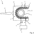
- FIG. 3 shows a cross-sectional arrangement of another embodiment of a device 1 for biological decontamination of percutaneous accesses in the plan view as a sectional view.
- the device 1 has a carrier 10 and a handle 11 on the carrier 10.
- the carrier 10 has a U-shaped curved recess 12 into which a tube-like structure 2 of a percutaneous access or stomata can be inserted.
- the device 1 is placed at a percutaneous access or stomata in such a way that the tubular structure 2 dips into the U-shaped recess 12.
- a treatment surface 3 of the plasma generator 4 is arranged on the inside of the U-shaped curved recess 12.
- the treatment surface 3 in turn has an insulating jacket 5, which electrically insulates a high-voltage electrode 6 from the ground electrode 7 and prevents voltage flashovers.
- the insulating body 5 with its high-voltage electrode 6 embedded therein is received in the U-shaped curved recess 12 of the carrier 10.
- a ground electrode 7 that can be connected to the ground potential of a high-voltage generator 4 is arranged on the outer surface of the insulating body 5, which forms the now free interior space of the U-shaped curved recess 12 for receiving the tubular structure 2 of a percutaneous access or stomatas.
- such a ground electrode 7 is also present on the opposite side of the insulating material jacket 5 adjacent to the handle 10. This ensures that the carrier 10 and the handle 11 attached to it are always connected to ground potential and grounded.
- the carrier 10 itself can also be made of an electrically conductive material and form the ground electrode 7.
- the ground electrode 7 is bound around the insulating material jacket 5 as a flexible wire electrode, so that the treatment surface 3 can be adapted to the curved U-shaped recess 12 of the carrier 10.
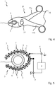
- FIG 4 shows a further embodiment of a device 1 for the biological decontamination of percutaneous accesses or stomata.
- This device has a pair of pliers 13 with two pliers levers 15a, 15b which are arranged around a pivot bearing 14 and are movable relative to one another and each have a pliers jaw 17 at their ends opposite the handle 16.
- the pliers jaws 17 are recessed in a trough-like manner so that they cover a partially circular or oval at least partially closed surface.
- a tube-like structure 2 of a percutaneous access or stomatas are introduced.
- the tong jaws 17 are first opened once with the aid of the tong levers 15a, 15b, the hose-like structure 2 is inserted between the tong jaws 17 and the tong 13 is then closed again.
- a treatment surface 3 in the manner described above is arranged on the facing inner surfaces of the tong jaws 17 and is connected to a plasma generator 4 (e.g. high-voltage generator).
- the treatment surface 3 has an insulating material jacket 5 which shields a high-voltage electrode 6 from a ground electrode 7.
- the ground electrodes 7 of the treatment area 3 are arranged on the free inner surface adjacent to the hose-like structure 2. In this way, for example, cold atmospheric gas plasma is generated on the free inside of the treatment surfaces 3 in order to biologically decontaminate the hose-like structure 2 of a percutaneous access or stomata and the tissue connected to it.
- Figure 5 leaves out an enlarged view of the treatment surfaces 3 for the device 1 Figure 4 recognize in the sectional view.
- the treatment surfaces 3 are adapted to the trough-like depression of the forceps jaws 17 in a curved manner.
- the treatment surfaces 13 are preferably formed from a flexible carrier in the form of the insulating jacket 5.
- the insulating material jacket 5 accommodates the high-voltage electrode 6, which is also curved in an adapted manner and which can be designed as a curved plate or as a rod.
- the ground electrode 7, which can be connected to the ground connection of the high-voltage generator 4, is arranged at least on the inside of the insulating jacket 5.
- the high-voltage electrodes 6 of the opposing treatment surfaces 3 are in turn connected to the high-voltage connection of the high-voltage generator 4 (plasma generator).
- the ground electrodes 7 are again designed as wound wire electrodes that surround the insulating jacket on both sides and rest on the top of the insulating jacket 5 both on the inside and on the outside that rests against the carrier 10.
- Treatment surfaces are also possible which at least partially enclose a tubular structure of a percutaneous access or stomatas or can be temporarily placed on the outer circumference of a percutaneous access or stomatas, for example with forceps, with plasma generated by a plasma generator as a gas flow or fluid flow be routed through cavities in the treatment area to the percutaneous access or stomata.
- the plasma used for biological decontamination is thus not generated directly on the treatment area, but in the plasma generator. From there it is directed to the treatment area.
- a treatment area can thus be a passive treatment area for distributing plasma generated in a plasma generator or an active treatment area for generating and spreading plasma over an area.
- “Apply” is understood to mean that the treatment surface rests directly on a tubular structure 2 of the percutaneous access or stomatas or is arranged directly at a distance from the tubular structure 2 with an intermediate space. It is therefore not necessary for the treatment surface 3 to necessarily touch the percutaneous access or the stomata. It only has to be applied in such a way that the plasma present on the treatment surface 3 comes into contact with the surface of the percutaneous access or the stomatas and possibly the tissue adjoining it in a decontaminating manner.
Landscapes
- Engineering & Computer Science (AREA)
- Health & Medical Sciences (AREA)
- Plasma & Fusion (AREA)
- Physics & Mathematics (AREA)
- Life Sciences & Earth Sciences (AREA)
- Surgery (AREA)
- Animal Behavior & Ethology (AREA)
- Veterinary Medicine (AREA)
- Nuclear Medicine, Radiotherapy & Molecular Imaging (AREA)
- Biomedical Technology (AREA)
- Public Health (AREA)
- General Health & Medical Sciences (AREA)
- Spectroscopy & Molecular Physics (AREA)
- Molecular Biology (AREA)
- Medical Informatics (AREA)
- Heart & Thoracic Surgery (AREA)
- Otolaryngology (AREA)
- Radiology & Medical Imaging (AREA)
- Electrotherapy Devices (AREA)
Description
- Die Erfindung betrifft eine Vorrichtung zur biologischen Dekontamination von perkutanen Zugängen oder Stomata von Patienten mit einem Plasmagenerator zur Erzeugung eines dekontaminierenden Plasmas angrenzend an eine Behandlungsfläche de Plasmagenerators.
- In der medizinischen Praxis sind für vielfältige Anwendungen verschiedenste Arten von perkutanen ("perkutan" = durch die Haut) Zugängen zu Organen und unterschiedlichen Bereichen im menschlichen Körper erforderlich. Hierzu werden beispielsweise Katheter jeglicher Art (z. B. Blasenkatheter, Ureterkatheter, Portkatheter, Tubenkatheter, Herzkatheter, Dialysekatheter, etc.) sowie vielfältige Arten von äußeren Drainagen (z. B. Redon-Drainage, Kapillar-Drainage, Shirley-Drainage, T-Drainage, Pankreas-Drainage, etc.) eingesetzt, die aus speziellem Schlauchmaterial gefertigt sind und der Ableitung von Körperflüssigkeiten, wie Blut, Gewebsflüssigkeit, Wundsekret und Eiter, wie sie insbesondere nach chirurgischen Eingriffen entstehen können, aus dem Körperinneren nach Außen dienen.
- Weiterhin werden für zahlreiche chirurgische Eingriffe ebenfalls chirurgisch angelegte künstliche Öffnungen in der Körperoberfläche (so genannte Stomata) genutzt. Stomata sind z. B. zur Ableitung des Inhalts von Hohlorganen nach Außen (Enterostoma, Colostoma, Ileostoma, Urostoma, Tracheostoma, Gastrostroma), wie beispielsweise im Falle einer künstlichen Darmverlegung (Enterostoma) oder einer künstlichen Harnableitung (Urostoma) etc., bei der Implantation von Endo-Exo-Prothesen, bei denen nach Extremitätenamputation ein knochenverankerter "Endostiel" zur Montage einer äußeren "Exo-Prothese" durch die Haut nach Außen geleitet wird, oder zur Verlegung von perkutanen Steuerkabeln (Drivelines), wie sie beispielsweise zur Verbindung eines implantierten ventrikulären Unterstützungssystems (VAD - ventricular assist device: eine Art "künstliches Herz") mit dem externen Steuergerät genutzt werden, notwendig.
- Ein Problem bei der Applikation derartiger Zugänge und Stomata stellt das Infektionsrisiko des betreffenden Hautareals dar. Das Infektionsrisiko in diesem Bereich ist besonders hoch, da einerseits die Haut als größtes Körperorgan, prinzipiell Keimen eine große Angriffsfläche bietet und andererseits Hautkeime durch die Katheter- bzw. Drainage-Eintrittsstellen in den Körper eindringen können, wo sie Komplikationen, wie eine Abszessbildung oder eine lebensbedrohende Sepsis (Blutvergiftung) verursachen können. Daher kommt der Vermeidung bzw. Reduzierung des Infektionsrisikos bei der Verlegung Nachsorge von perkutanen Zugängen und Stomata jeglicher Art eine wesentliche Rolle zu.
- Die einen perkutanen Zugang oder ein Stomata umgebenden Hautareale werden hierzu mit einem trocknen, sterilen Verband abgedeckt, regelmäßig inspiziert, gesäubert und antiseptisch behandelt, sowie ggf. prophylaktisch mit Antibiotika behandelt. Ggf. sind darüber hinaus, z.B. bei einer Besiedelung der Haut mit multiresistenten-Erregern, besondere Schutzmaßnahmen, wie beispielsweise eine Dekolonisierung der Haut erforderlich.
- Das Restrisiko für Infektionen ist bei perkutanen Zugängen und Stomata hoch, so dass eine weitere Reduzierung des Risikos anzustreben ist. Der Einsatz von Desinfektionsmitteln birgt das Problem von möglichen allergischen Reaktionen. Zudem sind die Desinfektionsmaßnahmen in der Regel zeit- und materialintensiv. Dies gilt insbesondere im Fall von prophylaktischen Maßnahmen gegen eine Infektion durch multi-resistente-Erreger. Zur Förderung einer Wundheilung sind neben den Desinfektionsmaßnahmen zusätzlich noch heilungsfördernde Maßnahmen erforderlich.
- Es ist hinreichend bekannt, dass Plasma eine desinfizierende Wirkung hat.
-
WO 2011/023478 A1 offenbart eine Vorrichtung zur flächigen Behandlung von Bereichen menschlicher oder tierischer Haut- bzw. Schleimhautoberflächen mittels eines kalten Atmosphärendruckplasmas. Hierzu wird eine Manschette mit einer in der Manschette eingebauten Elektrodenanordnung um ein Körperteil gewunden. Der zu behandelnde Bereich ist dabei vollständig durch die Manschette abgedeckt. - Aus
WO 2013/167693 A1 ist eine Vorrichtung zur Plasmabehandlung von menschlichen, tierischen oder pflanzlichen Oberflächen, insbesondere von Haut oder Schleimarealen bekannt. Die Vorrichtung hat eine Elektrodenanordnung, bei der die Hochspannungselektrode aus einem dünnen Draht besteht und mit einer Isolationsschicht ummantelt ist. Die geerdete Elektrode besteht aus einer gasdurchlässigen, textilen Flächenstruktur, die sich flexibel auf beliebig gekrümmte Oberflächen auflegen lässt. Ein Gerät nach der Präambel von Anspuch 1 ist ausDE202009011521 bekannt. - Ausgehend hiervon ist es Aufgabe der vorliegenden Erfindung eine Vorrichtung zur biologischen Dekontamination von perkutanen Zugängen oder Stomata vom Patienten zu schaffen.
- Die Aufgabe wird durch die Vorrichtung mit den Merkmalen des Anspruchs 1 gelöst.
- Vorteilhafte Ausführungsformen sind in den Unteransprüchen beschrieben.
- Es wird somit die Verwendung von dekontaminieserendem Plasma zur biologischen Dekontamination von perkutanen Zugängen oder Stomata vorgeschlagen, um dadurch die Infektionsprophylaxe einfacher und effektiver zu gestalten und zudem die Wundheilung zu fördern. Dies gelingt dadurch, dass eine Vorrichtung zur biologischen Dekontamination vom perkutanen Zugängen oder Stomata von Patienten einen Plasmagenerator mit einer Behandlungsfläche hat, die ein dekontaminierendes Plasma bereitstellt, wobei diese Behandlungsfläche zumindest teilweise Umfassen eines perkutanen Zugangs oder Stomata anpasst bei gekrümmt und an den perkutanen Zugang oder Stomata anlegbar ist.
- Durch die einen perkutanen Zugang oder Stomata mindestens teilweise umfassende Behandlungsfläche eines Plasmagenerators und durch Anlegen dieser anpassbar gekrümmten Behandlungsfläche an den perkutanen Zugang oder Stomata gelingt es, die Infektionsgefahr durch perkutane Zugänge oder Stomata auf zuverlässige und einfache Weise zu reduzieren. Hierzu kann der Plasmagenerator vorzugsweise zur Erzeugung eines kalten Atmosphärendruckplasmas an der Behandlungsfläche ausgebildet sein. Als Plasmaquellen sind z.B. prinzipiell Plasmajet-Anordnungen, DBE-Anordnung (DBE = dielektrisch behinderte Entladung) oder Korona-Anordnungen geeignet.
- Durch die Vorrichtung lässt sich eine deutliche Minimierung des Infektionsrisikos im Bereich von perkutanen Zugängen und Stomata erreichen. Zudem werden allergische Reaktionen vermieden, wie sie ansonsten bei einer Desinfektion von perkutanen Zugängen und Stomata durch Infektionsmittel oftmals auftreten. Weiterhin lassen sich Infektionen durch multi-resistente Erreger bei vergleichsweise geringen Zeit- und Materialaufwand wirksam vermeiden. Die Vorrichtung ermöglicht eine beträchtliche Zeit- und Materialeinsparung bei der Nutzung perkutaner Zugänge oder Stomata im Vergleich zur herkömmlichen Infektionsvorsorge. Weiterhin hat die Vorrichtung eine Förderung der Wundheilung zur Folge, da das zur Dekontamination genutzte Plasma nicht nur eine dekontaminierende, sondern auch eine wundheilungsfördernde Heilung hat.
- Ein schlauchförmiger perkutaner Zugang oder ein schlauchförmiges Stomata hat in einer bevorzugten Ausführungsform eine integral hiermit verbundene Behandlungsfläche an der Außenseite eines zum Einleiten oder Ableiten von flüssigkeitgenutzten flexiblen Schlauchs. Damit kann während der Nutzungszeit des perkutanen Zugangs oder des Stomatas permanent oder ohne zusätzliche Installationsarbeit wiederkehrend eine Plasmabehandlung des an die Behandlungsfläche angrenzenden Gewebebereichs erfolgen. Die Vorrichtung ist somit ein perkutaner Zugang oder ein Stomata mit einem schlauchförmigen Gebilde, das eine Plasmabehandlungsfläche hat, die an das schlauchförmige Gebilde anpassbar gekrümmt ist und dieses schlauchförmige Gebildet mindestens teilweise umgibt.
- Denkbar ist aber auch eine Ausführungsform, bei der die Behandlungsfläche zylinderförmig ist und der Innenraum der zylinderförmigen Behandlungsfläche zur Aufnahme eines Schlauchs eines perkutanen Zugangs oder Stomata vorgesehen ist. Vor der Nutzung des perkutanen Zugangs oder Stomatas wird somit die Behandlungsfläche des Plasmagenerators auf den Schlauch geschoben, um sodann bei der Anwendung permanente oder in Abständen wiederholt zur Dekontamination aktiviert zu werden.
- Denkbar ist aber auch, dass die Vorrichtung zur biologischen Dekontamination von perkutanen Zugängen oder Stomata ausgebildet ist, um temporär zur biologischen Dekontamination eingesetzt zu werden. Bei dieser Ausführungsform hat die Vorrichtung vorzugsweise einen Träger mit einem Handgriff und einer U-förmig gekrümmten Vertiefung. Die Behandlungsfläche des Plasmagenerators liegt dabei an der Innenwand der U-förmig gekrümmten Vertiefung an. Auf diese Weise kann die hierdurch U-förmig gekrümmte Behandlungsfläche angrenzend an dem perkutanen Zugang oder das Stomata im Bereich der Gewebeoberfläche platziert werden, so dass der perkutane Zugang oder das Stomata in die U-förmig gekrümmte Vertiefung eintaucht und an die Behandlungsfläche angrenzt. Dann wird nach Aktivierung des Plasmagenerators durch die Behandlungsfläche ein dekontaminierendes Plasma, wie vorzugsweise kaltes Atmosphärengasplasma, erzeugt und auf diese Weise eine Dekontamination des perkutanen Zugangs oder Stomatas und des angrenzenden Hautbereichs vorgenommen. Dies hat gleichzeitig eine wundfördernde Wirkung auf das Gewebe, welches an den perkutanen Zugang und das Stomata angrenzt.
- Eine andere zur temporären Dekontamination geeignete Vorrichtung zeichnet sich vorzugsweise dadurch aus, dass die Vorrichtung eine Zange mit zwei gegeneinander beweglich gelagerten Zangenbacken aufweist. An den einander zugewandten Innenflächen der Zangenbacken ist jeweils eine Behandlungsfläche angeordnet. Auf diese Weise kann die Behandlungsfläche das schlauchförmige Gebilde eines perkutanen Zugangs oder Stomata umgreifen und angrenzend hieran positioniert werden. Mit Hilfe der Zange gelingt es, die Behandlungsfläche an unterschiedliche Durchmesser anzupassen.
- Die Integration einer Plasma- Behandlungsfläche eines Plasmagenerators mit den Zangenbacken ermöglicht eine gute Handhabung einer Dekontaminationsvorrichtung, um insbesondere perkutane Zugänge und Stomata möglichst einfach und zuverlässig biologisch zu dekontaminieren.
- Für all die genannten Ausführungsformen der Vorrichtung ist es besonders vorteilhaft, wenn die Behandlungsfläche einen flexiblen Träger mit mindestens einer von dem flexiblen Träger umschlossenen Hochspannungselektrode und mit mindestens einer Masseelektrode an der Außenfläche des flexiblen Trägers aufweist. Der flexible Träger ist dabei aus einem geeigneten Isolationsmaterial, wie z.B. ein Dielektrikum ausgebildet und zwischen Hochspannungselektrode und Masselektrode angeordnet. Die Masselektrode befindet sich dabei an der Außenfläche des flexiblen Trägers, die zur Anordnung benachbart an das an dem perkutanen Zugang oder das Stomata vorgesehen ist. Damit wird beim Anlegen einer Hochspannung an die Hochspannungselektrode durch einen Plasmagenerator ein kaltes Atmosphärengasplasma an der die Masseelektrode tragenden Außenfläche des flexiblen Trägers erzeugt. Dieses Plasma kann dann auf das den angrenzenden perkutanen Zugang, ein angrenzendes Stomata und die daran angrenzenden Gewebebereiche eines Patienten wirken. Der Patient kann dabei ein Mensch oder ein Tier sein.
- Die Masseelektrode ist eine um den flexiblen Träger gewickelte Drahtwicklung. Die Hochspannungselektrode ist dabei beidseits durch einen flexiblen Träger abgedeckt und somit in den Zwischenraum eines flexiblen Trägers angeordnet. Damit wird bei einer rohrförmigen Behandlungsfläche erreicht, dass sowohl die zylinderförmige Innenfläche, als auch die Außenfläche eine Masseelektrode aufweist. Auf diese Weise wird die Gefahr vor elektrischer Hochspannung reduziert.
- Eine mit einer Masseelektrode versehende Außenfläche des flexiblen Trägers kann dann z.B. an eine U-förmig gekrümmte Vertiefung eines Trägers oder an einer Zangenbacke einer Zange angebracht werden, die damit elektrisch geerdet ist.
- Zumindest eine Masseelektrode sollte jedenfalls an der zur Anlage an dem perkutanen Zugang oder dem Stomata vorgesehenen Oberfläche der Behandlungsfläche angeordnet sein.
- Die Hochspannungselektrode ist besonders vorteilhaft als flexible Drahtelektrode ausgeführt. Sie kann aber auch z.B. aus einem Gitterelement gebildet sein.
- Besonders vorteilhaft ist es, wenn der flexible Träger aus einem dielektrischen Kunststoffmaterial, insbesondere aus Polyimid, gebildet ist. Ein solches dielektrisches Kunststoffmaterial eignet sich besonders zur Erzeugung von Plasma mittels Hochspannung. Durch eine besonders hohe, stabile elektrische Spannungsfertigkeit und Plasmabeständigkeit zeichnet sich das Polyimid "Kapton ® CR" der Firma Du Pont aus.
- Die Erfindung wird nachfolgend anhand von Ausführungsbeispielen mit den beigefügten Zeichnungen näher erläutert. Es zeigen:
- Figur 1
- - Querschnittsansicht einer ersten Ausführungsform einer Vorrichtung zur biologischen Dekontamination von perkutanen Zugängen oder Stomata mit einem schlauchartigen Gebilde, das von einer Plasma- Behandlungsfläche umschlossen ist;
- Figur 2
- - Seiten- Teilschnittansicht einer flexibel an einen perkutanen Zugang oder ein Stomata anpassbaren Vorrichtung zur biologischen Dekontamination ;
- Figur 3
- - Draufsicht auf eine Ausführungsform einer handgeführten Vorrichtung zur biologischen Dekontamination von perkutanen Zugängen oder Stomata;
- Figur 4
- - Skizze einer als Zange ausgeführten Vorrichtung zur biologischen Dekontamination von perkutanen Zugängen oder Stomata;
- Figur 5
- - Skizze der in die Zangenbacken der Zange aus
Figur 4 integrierbaren Behandlungsfläche. -
Figur 1 zeigt eine Vorrichtung 1 zur biologischen Dekontamination von perkutanen Zugängen oder Stomata. Ein solcher perkutaner Zugang oder Stomata hat ein schlauchartiges Gebilde 2, an dessen Außenumfang eine Behandlungsfläche eines Plasmagenerators angeordnet ist. Der Plasmagenerator selbst ist ein Generator, der eine Hochspannung erzeugt, wie sie durch den Hochspannungspfeil angedeutet ist. - Die Behandlungsfläche 3 hat einen das schlauchförmige Gebilde 2 umgebenden Isolierstoffmantel 5, in den eine Hochspannungselektrode 6 eingebettet ist. An den beiden Außenseiten des Isolierstoffmantels 5 ist jeweils eine Masseelektrode 7 angeordnet. Diese kann beispielsweise als um den Isolierstoffmantel 5 gewundene Drahtwicklung ausgeführt sein. Denkbar ist aber auch, dass ein Gewebe oder Gitter aus einem elektrisch leitfähigen Material, insbesondere ein Metallgitter, auf der zylinderförmigen Innenfläche und/oder der zylinderförmigen Außenfläche des Isolierstoffmantels 5 angebracht und jeweils mit Massepotential GND verbunden ist.
- Hierzu sind ein Masseanschluss 8, der mit der Masseelektrode 7 elektrisch leitend verbunden ist, sowie ein Hochspannungsanschluss 9, der mit der Hochspannungselektrode elektrisch leitend verbunden ist, an die Außenseite der Vorrichtung 1 geführt, um den Hochspannungsgenerator 4 an die Behandlungsfläche 3 anzuschließen.
- Durch Beaufschlagung der Hochspannungselektrode 6 mit einer Hochspannung entweder als Gleichspannung, als gepulste Gleichspannung oder Wechselspannung wird in an sich bekannter Weise ein kaltes Atmosphärengasplasma an den Masseelektrodenflächen erzeugt. Dieses Plasma bildet sich dabei in den Luftzwischenräumen der Masseelektroden 7 und tritt dabei an der Oberfläche des schlauchartigen Gebildes 2 auf. Der so erzeugte Plasmastrom gelangt weiterhin an die angrenzenden Gewebeflächen. Auf diese Weise wird eine biologische Dekontamination des schlauchartigen Gebildes 2 des perkutanen Zugangs oder Stomatas und des angrenzendes Gewebes bewirkt. Zudem wird durch das Plasma die Wundheilung des angrenzenden Gewebes verbessert.
-
Figur 2 lässt eine perspektivische Seiten-Teilschnittansicht einer Vorrichtung zur Erzeugung einer dielektrisch behinderten Entladung (DBE) mit Hilfe einer Drahtanordnung erkennen. Die Hochspannungselektrode 6 besteht hierbei aus einem Draht, der mit einem geeigneten Isolationsmaterial 5 ummantelt ist. Als geerdete Masseelektrode 7 wird ein Metalldraht verwendet, der spiralförmig den Isolierstoffmantel 5 und die darin eingebettete Hochspannungselektrode 6 umgibt. Werden die Hochspannungselektrode 6 und die Masseelektrode 7 an einen speziellen Hochspannungsgenerator angeschlossen, so wird bei Wahl einer geeigneten Frequenz und Einstellung eines ausreichenden Wertes der Spannung an der Hochspannungselektrode auf der Oberfläche des Isolierstoffmantels 5 im Bereich der spiralförmigen geerdeten Masseelektrode 7 ein Plasma erzeugt. Der Vorteil dieser Elektrodenanordnung besteht vor allem darin, dass sich die Plasmaquelle aufgrund der Flexibilität der Drahtanordnung der Hochspannungselektrode 5 und der Masseelektrode 6 einfach an unterschiedlichste Formen und Größen der perkutanen Zugänge und Stomata anpassen lässt. So kann die Anordnung beispielsweise spiralförmig um ein schlauchartiges Gebilde gewickelt werden. Denkbar ist auch, dass die Vorrichtung 1 teilkreisförmig oder vollkreisförmig geschlossen um die Einführstelle eines perkutanen Zugangs oder Stomatas in einen menschlichen oder tierischen Körper herumgelegt wird, um diesen Wundbereich permanent oder zeitweise zu dekontaminieren. - Wesentlich für die in
Figur 2 dargestellte Anordnung ist, dass der Isolierstoffmantel 5, die Hochspannungselektrode 6 und die als Drahtwicklung ausgeführte Masseelektrode 7 zusammen eine flexible an einen gekrümmten perkutanen Zugang oder Stomata anpassbare Anordnung bildet. -
Figur 3 lässt eine Querschnittsanordnung einer anderen Ausführungsform einer Vorrichtung 1 zur biologischen Dekontamination von perkutanen Zugängen in der Draufsicht als Schnittansicht erkennen. Hierbei hat die Vorrichtung 1 einen Träger 10 und einem Handgriff 11 an dem Träger 10. Der Träger 10 hat eine U-förmig gekrümmte Vertiefung 12, in die ein schlauchartiges Gebilde 2 eines perkutanen Zugangs oder Stomata eingeführt werden kann. Die Vorrichtung 1 wird dabei in der Praxis an einem perkutanen Zugang oder Stomata so platziert, dass das schlauchförmige Gebilde 2 in die U-förmige Vertiefung 12 eintaucht. An der Innenseite der U-förmig gekrümmten Vertiefung 12 ist eine Behandlungsfläche 3 des Plasmagenerators 4 angeordnet. Die Behandlungsfläche 3 hat wiederum einen Isolierstoffmantel 5, der eine Hochspannungselektrode 6 elektrisch gegenüber der Masseelektrode 7 isoliert und Spannungsüberschläge verhindert. - Der Isolierstoffkörper 5 mit seiner darin eingebetteten Hochspannungselektrode 6 ist in der U-förmig gekrümmten Vertiefung 12 des Trägers 10 aufgenommen. An der Außenfläche des Isolierstoffkörpers 5, die den nunmehr freien Innenraum der U-förmig gekrümmten Vertiefung 12 zur Aufnahme des schlauchförmigen Gebildes 2 eines perkutanen Zugangs oder Stomatas bildet, ist eine mit Massepotential eines Hochspannungsgenerators 4 verbindbare Masseelektrode 7 angeordnet.
- In dem dargestellten Ausführungsbeispiel ist auf der gegenüberliegenden Seite des Isolierstoffmantels 5 angrenzend an den Handgriff 10 ebenfalls eine solche Masseelektrode 7 vorhanden. Damit wird sichergestellt, dass der Träger 10 und der daran angebrachte Handgriff 11 auf jeden Fall mit Massepotential verbunden und geerdet ist. Hierzu kann aber auch der Träger 10 selbst aus einem elektrisch leitenden Material sein und die Masseelektrode 7 bilden.
- In dem dargestellten Ausführungsbeispiel ist die Masseelektrode 7 als flexible Drahtelektrode um den Isolierstoffmantel 5 gebunden, so dass die Behandlungsfläche 3 an die gekrümmte U-förmige Vertiefung 12 des Trägers 10 angepasst werden kann.
-
Figur 4 lässt eine weitere Ausführungsform einer Vorrichtung 1 zur biologischen Dekontamination von perkutanen Zugängen oder Stomata erkennen. Diese Vorrichtung hat eine Zange 13 mit zwei relativ zueinander beweglich um ein Schwenklager 14 angeordneten Zangenhebel 15a, 15b, die jeweils an ihrem den Griff 16 gegenüberliegenden Enden eine Zangenbacke 17 haben. Die Zangenbacken 17 sind muldenartig vertieft, so dass sie eine teilkreisförmig oder ovale mindestens teilweise geschlossene Fläche überdecken. In den Zwischenraum zwischen den beiden Zangenbacken 17 kann ein schlauchartiges Gebilde 2 eines perkutanen Zugangs oder Stomatas eingebracht werden. Hierzu werden die Zangenbacken 17 mit Hilfe der Zangenhebel 15a, 15b erst einmal geöffnet, das schlauchartige Gebilde 2 zwischen die Zangenbacken 17 eingeführt und die Zange 13 dann wieder geschlossen. - Deutlich wird, dass an den einander zugewandten Innenflächen der Zangenbacken 17 jeweils eine Behandlungsfläche 3 in der vorher beschriebenen Art angeordnet ist, die mit einem Plasmagenerator 4 (z.B. Hochspannungsgenerator) verbunden wird. Die Behandlungsfläche 3 hat in der vorher beschriebenen Weise einen Isolierstoffmantel 5, der eine Hochspannungselektrode 6 gegenüber einer Masseelektrode 7 abschirmt. Die Masseelektroden 7 der Behandlungsfläche 3 ist an der freien innen liegenden Oberfläche angrenzend an das schlauchartige Gebilde 2 angeordnet. Damit wird z.B. kaltes Atmosphärengasplasma an der freien Innenseite der Behandlungsflächen 3 erzeugt, um auf diese Weise das schlauchartige Gebilde 2 eines perkutanen Zugangs oder Stomata sowie daran anschließendes Gewebe biologisch zu dekontaminieren.
-
Figur 5 lässt eine vergrößerte Ansicht der Behandlungsflächen 3 für die Vorrichtung 1 ausFigur 4 in der Schnittdarstellung erkennen. Deutlich wird, dass die Behandlungsflächen 3 an die muldenartige Vertiefung der Zangenbacken 17 gekrümmt angepasst sind. Hierzu sind die Behandlungsflächen 13 vorzugsweise aus eine flexiblen Träger in Form des Isolierstoffmantels 5 gebildet. Der Isolierstoffmantel 5 nimmt, wie bei den vorhergehenden Ausführungsformen die ebenfalls angepasst gekrümmte Hochspannungselektrode 6 auf, die als gebogene Platte oder als Stab ausgeführt sein kann. Mindestens an der Innenseite des Isolierstoffmantels 5 ist die Masseelektrode 7 angeordnet, welche mit dem Masseanschluss des Hochspannungsgenerators 4 verbindbar ist. Die Hochspannungselektroden 6 der einander gegenüberliegenden Behandlungsflächen 3 sind ihrerseits mit dem Hochspannungsanschluss des Hochspannungsgenerators 4 (Plasmagenerators) verbunden. - In der dargestellten Ausführungsform sind die Masseelektroden 7 wiederum als gewickelte Drahtelektroden ausgeführt, die beidseits den Isolierstoffmantel umgeben und sowohl an der Innenseite, als auch an der Außenseite, die an dem Träger 10 anliegt, auf der Oberseite des Isolierstoffmantels 5 aufliegen.
- Weitere Formen dieser Vorrichtung sind denkbar. Neben diesen dargestellten Drahtanordnungen in O-form, U-form oder Zangenform sind auch spiralförmige, stiftförmige oder ähnliche Ausführungsformen der Behandlungsfläche denkbar. Möglich sind auch Behandlungsflächen, die ein schlauchförmiges Gebilde eines perkutanen Zugangs oder Stomatas mindestens teilweise umschließen oder z.B. mit einer Zange temporär an dem Außenumfang eines perkutanen Zugangs oder Stomatas platziert werden können, wobei von einem Plasmagenerator erzeugtes Plasma als Gasstrom oder Fluidstrom durch Hohlräume der Behandlungsfläche zu dem perkutanen Zugang oder Stomata geleitet werden. Bei dieser Ausführungsform wird das zur biologischen Dekontaminierung verwendete Plasma somit nicht direkt an der Behandlungsfläche erzeugt, sondern in dem Plasmagenerator. Von dort wird es zur Behandlungsfläche geleitet.
- Im Sinne der vorliegenden Erfindung kann eine Behandlungsfläche somit eine passive Behandlungsfläche zum Verteilen von in einem Plasmagenerator erzeugten Plasma oder eine aktive Behandlungsfläche zum Erzeugen und flächigem Verbreiten von Plasma sein.
- Eine biologische Dekontamination von perkutanen Zugängen oder Stomata von menschlichen oder tierischen Patienten erfolgt mit einer seiner oben beschriebenen Vorrichtung 1 durch die Verfahrensschritte
- mindestens teilweises Umfassen des perkutanen Zugangs oder Stomatas mit einer gekrümmten Behandlungsfläche eines Plasmagenerators;
- Anlegen der Behandlungsfläche an dem perkutanen Zugang oder der Stomata und
- Erzeugen von dekontaminierendem Plasma an der am perkutanen Zugang oder dem Stomata anliegenden Behandlungsfläche.
- Unter "Anlegen" wird verstanden, dass die Behandlungsfläche direkt an einem schlauchförmigen Gebilde 2 des perkutanen Zugangs oder Stomatas anliegt oder unmittelbar beabstandet zu dem schlauchförmigen Gebilde 2 mit einem Zwischenraum angrenzend angeordnet ist. Es ist somit nicht erforderlich, dass die Behandlungsfläche 3 dem perkutanen Zugang oder das Stomata zwingend berühren muss. Es muss nur derart anliegen, dass an der Behandlungsfläche 3 vorhandenes Plasma dekontaminierend wirksam mit der Oberfläche des perkutanen Zugangs oder des Stomatas und ggf. des daran angrenzenden Gewebes in Verbindung tritt.
Claims (9)
- Vorrichtung (1) zur biologischen Dekontamination von perkutanen Zugängen oder Stomata von Patienten mit einem Plasmagenerator (4) zur Erzeugung eines dekontaminierenden Plasmas angrenzend an eine Behandlungsfläche (3) des Plasmagenerators (4), wobei die Behandlungsfläche (3) zum mindestens teilweisen Umfassen eines perkutanen Zugangs oder Stomata anpassbar gekrümmt und an den perkutanen Zugang oder das Stomata anlegbar ist, wobei die Behandlungsfläche (3) einen flexiblen Träger (5) mit mindestens einer von dem flexiblen Träger (5) umschlossenen Hochspannungselektrode (6) und mit mindestens einer Masseelektrode (7) an der Außenfläche des flexiblen Trägers (5) hat,
dadurch gekennzeichnet, dass
die Masseelektrode (7) eine um den flexiblen Träger (5) gewickelte Drahtwicklung ist. - Vorrichtung (1) nach Anspruch 1, dadurch gekennzeichnet, dass die Vorrichtung einen Träger (10) mit einem Handgriff (11) und einer U-förmig gekrümmten Vertiefung (12) hat, und dass die Behandlungsfläche (3) des Plasmagenerators (4) an der Innenwand der U-förmig gekrümmten Vertiefung (12) anliegt.
- Vorrichtung (1) nach Anspruch 1, dadurch gekennzeichnet, dass die Behandlungsfläche (3) zylinderförmig ist und der Innenraum der zylinderförmigen Behandlungsfläche (3) zur Aufnahme eines Schlauchs (2) eines perkutanen Zugangs vorgesehen ist.
- Vorrichtung (1) nach Anspruch 1, dadurch gekennzeichnet, dass die Vorrichtung (1) eine Zange (13) mit zwei gegeneinander beweglich gelagerten Zangenbacken (17) hat, und dass jeweils eine Behandlungsfläche (3) an den einander zugewandten Innenflächen der Zangenbacken (17) angeordnet ist.
- Vorrichtung nach Anspruch 1, dadurch gekennzeichnet, dass die Masseelektrode (7) an der zur Anlage an den perkutanen Zugang oder dem Stomata vorgesehenen Außenseite der Behandlungsfläche (3) angeordnet ist.
- Vorrichtung (1) nach einem der Ansprüche 1 oder 5, dadurch gekennzeichnet, dass die Hochspannungselektrode (6) eine flexible Drahtelektrode ist.
- Vorrichtung (1) nach einem der vorhergehenden Ansprüche, dadurch gekennzeichnet, dass der flexible Träger (5) aus einem dielektrischen Kunststoffmaterial, insbesondere Polyimid, gebildet ist.
- Vorrichtung (1) nach einem der vorhergehenden Ansprüche, dadurch gekennzeichnet, dass der Plasmagenerator (4) mit seiner mindestens einen Behandlungsfläche (3) zur Erzeugung von kaltem Atmosphärendruckplasma eingerichtet ist.
- Verwendung einer Vorrichtung (1) nach einem Ansprüche 1 bis 8 zur biologischen Dekontamination von perkutanen Zugängen oder Stomata von Patienten.
Applications Claiming Priority (2)
| Application Number | Priority Date | Filing Date | Title |
|---|---|---|---|
| DE102014107554.4A DE102014107554A1 (de) | 2014-05-28 | 2014-05-28 | Vorrichtung zur biologischen Dekontamination von perkutanen Zugängen und Verfahren hierzu |
| PCT/EP2015/061900 WO2015181325A1 (de) | 2014-05-28 | 2015-05-28 | Vorrichtung zur biologischen dekontamination von perkutanen zugängen und verfahren hierzu |
Publications (2)
| Publication Number | Publication Date |
|---|---|
| EP3148464A1 EP3148464A1 (de) | 2017-04-05 |
| EP3148464B1 true EP3148464B1 (de) | 2021-03-03 |
Family
ID=53433165
Family Applications (1)
| Application Number | Title | Priority Date | Filing Date |
|---|---|---|---|
| EP15729767.2A Active EP3148464B1 (de) | 2014-05-28 | 2015-05-28 | Vorrichtung zur biologischen dekontamination von perkutanen zugängen und verfahren hierzu |
Country Status (6)
| Country | Link |
|---|---|
| US (1) | US20170216614A1 (de) |
| EP (1) | EP3148464B1 (de) |
| DE (1) | DE102014107554A1 (de) |
| DK (1) | DK3148464T3 (de) |
| ES (1) | ES2869456T3 (de) |
| WO (1) | WO2015181325A1 (de) |
Families Citing this family (4)
| Publication number | Priority date | Publication date | Assignee | Title |
|---|---|---|---|---|
| DE102012207750A1 (de) * | 2012-05-09 | 2013-11-28 | Leibniz-Institut für Plasmaforschung und Technologie e.V. | Vorrichtung zur plasmabehandlung von menschlichen, tierischen oder pflanzlichen oberflächen, insbesondere von haut oder schleimhautarealen |
| NL2013903B1 (nl) * | 2014-12-02 | 2016-10-11 | Stomydo B V | Houder voor een stoma-verband. |
| KR101635718B1 (ko) * | 2016-01-29 | 2016-07-01 | 김민기 | 플라즈마를 이용한 이미용장치 |
| US20200297881A1 (en) | 2016-03-16 | 2020-09-24 | Leibniz-Institut Fuer Plasmaforschung Und Technologie E. V. | Device, system, and method for antimicrobial treatment, method for producing the device, and computer program |
Family Cites Families (7)
| Publication number | Priority date | Publication date | Assignee | Title |
|---|---|---|---|---|
| US6455014B1 (en) * | 1999-05-14 | 2002-09-24 | Mesosystems Technology, Inc. | Decontamination of fluids or objects contaminated with chemical or biological agents using a distributed plasma reactor |
| EP1773227B1 (de) * | 2004-06-24 | 2016-04-13 | ArthroCare Corporation | Elektrochirurgische vorrichtung mit planaren vertikalen elektroden |
| US8521274B2 (en) * | 2005-04-25 | 2013-08-27 | Drexel University | Methods for non-thermal application of gas plasma to living tissue |
| DE202009011521U1 (de) * | 2009-08-25 | 2010-12-30 | INP Greifswald Leibniz-Institut für Plasmaforschung und Technologie e. V. | Plasma-Manschette |
| US9788882B2 (en) * | 2011-09-08 | 2017-10-17 | Arthrocare Corporation | Plasma bipolar forceps |
| DE102012207750A1 (de) | 2012-05-09 | 2013-11-28 | Leibniz-Institut für Plasmaforschung und Technologie e.V. | Vorrichtung zur plasmabehandlung von menschlichen, tierischen oder pflanzlichen oberflächen, insbesondere von haut oder schleimhautarealen |
| DE102013103248A1 (de) * | 2013-03-28 | 2014-10-02 | Adelheid Mirwald | Verfahren zur Erzeugung eines sterilen Bereiches für eine Operation, Untersuchung oder Behandlung wenigstens eines Teilbereiches eines Objekts, insbesondere einer Person |
-
2014
- 2014-05-28 DE DE102014107554.4A patent/DE102014107554A1/de not_active Withdrawn
-
2015
- 2015-05-28 EP EP15729767.2A patent/EP3148464B1/de active Active
- 2015-05-28 WO PCT/EP2015/061900 patent/WO2015181325A1/de not_active Ceased
- 2015-05-28 DK DK15729767.2T patent/DK3148464T3/da active
- 2015-05-28 US US15/313,558 patent/US20170216614A1/en not_active Abandoned
- 2015-05-28 ES ES15729767T patent/ES2869456T3/es active Active
Non-Patent Citations (1)
| Title |
|---|
| None * |
Also Published As
| Publication number | Publication date |
|---|---|
| DE102014107554A1 (de) | 2015-12-03 |
| US20170216614A1 (en) | 2017-08-03 |
| ES2869456T3 (es) | 2021-10-25 |
| DK3148464T3 (da) | 2021-05-17 |
| WO2015181325A1 (de) | 2015-12-03 |
| EP3148464A1 (de) | 2017-04-05 |
Similar Documents
| Publication | Publication Date | Title |
|---|---|---|
| EP1847227B1 (de) | Elektrisches Marknagelsystem | |
| EP3171676B1 (de) | Plasmaerzeugungsvorrichtung, plasmaerzeugungssystem und verfahren zur erzeugung von plasma | |
| DE102012015483B3 (de) | Elektrodenanordnung für eine Plasmabehandlung und Vorrichtung zur Herstellung einer transkutanen Verbindung | |
| EP3069578B1 (de) | Gerät zur behandlung einer körperoberfläche eines lebenden körpers | |
| EP3148464B1 (de) | Vorrichtung zur biologischen dekontamination von perkutanen zugängen und verfahren hierzu | |
| EP3669620B1 (de) | Plasma-behandlungsgerät für eine dielektrische barrierenentladung | |
| EP2987469B1 (de) | Einrichtung mit einer zum engen umschliessen eines körperteils ausgebildeten wandung | |
| DE202010015346U1 (de) | Elektrode zur Stimulation von Nerven | |
| DE102012103362A1 (de) | Plasma-Behandlungsgerät | |
| EP3897755A1 (de) | Liner für amputationsstumpf | |
| EP3429640B1 (de) | Vorrichtung und system zur antimikrobiellen behandlung | |
| EP2455018B1 (de) | Trokarhülse zum Einsetzen in eine Hautinzision | |
| EP3471642B1 (de) | Chirurgisches instrument für die elektrotomie und werkzeug dafür | |
| DE19714907C1 (de) | Abdichtvorrichtung für ein in einen menschlichen oder tierischen Körper einzuführendes Hautdurchleitungselement | |
| DE202010005677U1 (de) | Polypektomieschlinge | |
| DE202010008674U1 (de) | Chirurgisches Instrument | |
| DE102008005377A1 (de) | Bipolare Elektrode | |
| WO2005042078A1 (de) | Vorrichtung, insbesondere schleuse oder katheter, zum zumindest teilweisen einführen in einen körpergang | |
| EP1466566B1 (de) | Infektionsschutzvorrichtung für Endoexo-Implantate | |
| EP4509078A1 (de) | Ablationsinstrument und herstellungsverfahren für dieses | |
| EP4371580A1 (de) | Aufsatz zum reinigen von implantaten | |
| EP4346627A1 (de) | Chirurgische vorrichtung zur verklemmung in gewebe | |
| DE202011003353U1 (de) | Elektrodenkatheter zur Stimulation des Gehirns | |
| DE102006013304A1 (de) | Vorrichtung zur Keimreduktion oder Keimabtötung in natürlichen oder künstlichen Körperöffnungen | |
| DE102015104583A1 (de) | Implantierbare Vorrichtung zum Ausbilden einer permanenten Hautdurchführung |
Legal Events
| Date | Code | Title | Description |
|---|---|---|---|
| STAA | Information on the status of an ep patent application or granted ep patent |
Free format text: STATUS: THE INTERNATIONAL PUBLICATION HAS BEEN MADE |
|
| PUAI | Public reference made under article 153(3) epc to a published international application that has entered the european phase |
Free format text: ORIGINAL CODE: 0009012 |
|
| STAA | Information on the status of an ep patent application or granted ep patent |
Free format text: STATUS: REQUEST FOR EXAMINATION WAS MADE |
|
| 17P | Request for examination filed |
Effective date: 20161130 |
|
| AK | Designated contracting states |
Kind code of ref document: A1 Designated state(s): AL AT BE BG CH CY CZ DE DK EE ES FI FR GB GR HR HU IE IS IT LI LT LU LV MC MK MT NL NO PL PT RO RS SE SI SK SM TR |
|
| AX | Request for extension of the european patent |
Extension state: BA ME |
|
| DAV | Request for validation of the european patent (deleted) | ||
| DAX | Request for extension of the european patent (deleted) | ||
| GRAP | Despatch of communication of intention to grant a patent |
Free format text: ORIGINAL CODE: EPIDOSNIGR1 |
|
| STAA | Information on the status of an ep patent application or granted ep patent |
Free format text: STATUS: GRANT OF PATENT IS INTENDED |
|
| INTG | Intention to grant announced |
Effective date: 20200610 |
|
| GRAS | Grant fee paid |
Free format text: ORIGINAL CODE: EPIDOSNIGR3 |
|
| GRAA | (expected) grant |
Free format text: ORIGINAL CODE: 0009210 |
|
| STAA | Information on the status of an ep patent application or granted ep patent |
Free format text: STATUS: THE PATENT HAS BEEN GRANTED |
|
| AK | Designated contracting states |
Kind code of ref document: B1 Designated state(s): AL AT BE BG CH CY CZ DE DK EE ES FI FR GB GR HR HU IE IS IT LI LT LU LV MC MK MT NL NO PL PT RO RS SE SI SK SM TR |
|
| RAP1 | Party data changed (applicant data changed or rights of an application transferred) |
Owner name: LEIBNIZ-INSTITUT FUER PLASMAFORSCHUNG UND TECHNOLOGIE E.V. |
|
| REG | Reference to a national code |
Ref country code: GB Ref legal event code: FG4D Free format text: NOT ENGLISH |
|
| REG | Reference to a national code |
Ref country code: AT Ref legal event code: REF Ref document number: 1366362 Country of ref document: AT Kind code of ref document: T Effective date: 20210315 Ref country code: CH Ref legal event code: EP |
|
| REG | Reference to a national code |
Ref country code: DE Ref legal event code: R096 Ref document number: 502015014344 Country of ref document: DE |
|
| REG | Reference to a national code |
Ref country code: IE Ref legal event code: FG4D Free format text: LANGUAGE OF EP DOCUMENT: GERMAN |
|
| REG | Reference to a national code |
Ref country code: DK Ref legal event code: T3 Effective date: 20210510 |
|
| REG | Reference to a national code |
Ref country code: NO Ref legal event code: T2 Effective date: 20210303 |
|
| REG | Reference to a national code |
Ref country code: SE Ref legal event code: TRGR |
|
| REG | Reference to a national code |
Ref country code: LT Ref legal event code: MG9D |
|
| PG25 | Lapsed in a contracting state [announced via postgrant information from national office to epo] |
Ref country code: BG Free format text: LAPSE BECAUSE OF FAILURE TO SUBMIT A TRANSLATION OF THE DESCRIPTION OR TO PAY THE FEE WITHIN THE PRESCRIBED TIME-LIMIT Effective date: 20210603 Ref country code: FI Free format text: LAPSE BECAUSE OF FAILURE TO SUBMIT A TRANSLATION OF THE DESCRIPTION OR TO PAY THE FEE WITHIN THE PRESCRIBED TIME-LIMIT Effective date: 20210303 Ref country code: HR Free format text: LAPSE BECAUSE OF FAILURE TO SUBMIT A TRANSLATION OF THE DESCRIPTION OR TO PAY THE FEE WITHIN THE PRESCRIBED TIME-LIMIT Effective date: 20210303 Ref country code: GR Free format text: LAPSE BECAUSE OF FAILURE TO SUBMIT A TRANSLATION OF THE DESCRIPTION OR TO PAY THE FEE WITHIN THE PRESCRIBED TIME-LIMIT Effective date: 20210604 Ref country code: LT Free format text: LAPSE BECAUSE OF FAILURE TO SUBMIT A TRANSLATION OF THE DESCRIPTION OR TO PAY THE FEE WITHIN THE PRESCRIBED TIME-LIMIT Effective date: 20210303 |
|
| REG | Reference to a national code |
Ref country code: NL Ref legal event code: MP Effective date: 20210303 |
|
| PG25 | Lapsed in a contracting state [announced via postgrant information from national office to epo] |
Ref country code: PL Free format text: LAPSE BECAUSE OF FAILURE TO SUBMIT A TRANSLATION OF THE DESCRIPTION OR TO PAY THE FEE WITHIN THE PRESCRIBED TIME-LIMIT Effective date: 20210303 Ref country code: LV Free format text: LAPSE BECAUSE OF FAILURE TO SUBMIT A TRANSLATION OF THE DESCRIPTION OR TO PAY THE FEE WITHIN THE PRESCRIBED TIME-LIMIT Effective date: 20210303 Ref country code: RS Free format text: LAPSE BECAUSE OF FAILURE TO SUBMIT A TRANSLATION OF THE DESCRIPTION OR TO PAY THE FEE WITHIN THE PRESCRIBED TIME-LIMIT Effective date: 20210303 |
|
| PG25 | Lapsed in a contracting state [announced via postgrant information from national office to epo] |
Ref country code: NL Free format text: LAPSE BECAUSE OF FAILURE TO SUBMIT A TRANSLATION OF THE DESCRIPTION OR TO PAY THE FEE WITHIN THE PRESCRIBED TIME-LIMIT Effective date: 20210303 |
|
| REG | Reference to a national code |
Ref country code: ES Ref legal event code: FG2A Ref document number: 2869456 Country of ref document: ES Kind code of ref document: T3 Effective date: 20211025 |
|
| PG25 | Lapsed in a contracting state [announced via postgrant information from national office to epo] |
Ref country code: CZ Free format text: LAPSE BECAUSE OF FAILURE TO SUBMIT A TRANSLATION OF THE DESCRIPTION OR TO PAY THE FEE WITHIN THE PRESCRIBED TIME-LIMIT Effective date: 20210303 Ref country code: EE Free format text: LAPSE BECAUSE OF FAILURE TO SUBMIT A TRANSLATION OF THE DESCRIPTION OR TO PAY THE FEE WITHIN THE PRESCRIBED TIME-LIMIT Effective date: 20210303 Ref country code: SM Free format text: LAPSE BECAUSE OF FAILURE TO SUBMIT A TRANSLATION OF THE DESCRIPTION OR TO PAY THE FEE WITHIN THE PRESCRIBED TIME-LIMIT Effective date: 20210303 |
|
| PG25 | Lapsed in a contracting state [announced via postgrant information from national office to epo] |
Ref country code: SK Free format text: LAPSE BECAUSE OF FAILURE TO SUBMIT A TRANSLATION OF THE DESCRIPTION OR TO PAY THE FEE WITHIN THE PRESCRIBED TIME-LIMIT Effective date: 20210303 Ref country code: RO Free format text: LAPSE BECAUSE OF FAILURE TO SUBMIT A TRANSLATION OF THE DESCRIPTION OR TO PAY THE FEE WITHIN THE PRESCRIBED TIME-LIMIT Effective date: 20210303 Ref country code: PT Free format text: LAPSE BECAUSE OF FAILURE TO SUBMIT A TRANSLATION OF THE DESCRIPTION OR TO PAY THE FEE WITHIN THE PRESCRIBED TIME-LIMIT Effective date: 20210705 Ref country code: IS Free format text: LAPSE BECAUSE OF FAILURE TO SUBMIT A TRANSLATION OF THE DESCRIPTION OR TO PAY THE FEE WITHIN THE PRESCRIBED TIME-LIMIT Effective date: 20210703 |
|
| REG | Reference to a national code |
Ref country code: DE Ref legal event code: R097 Ref document number: 502015014344 Country of ref document: DE |
|
| PLBE | No opposition filed within time limit |
Free format text: ORIGINAL CODE: 0009261 |
|
| STAA | Information on the status of an ep patent application or granted ep patent |
Free format text: STATUS: NO OPPOSITION FILED WITHIN TIME LIMIT |
|
| PG25 | Lapsed in a contracting state [announced via postgrant information from national office to epo] |
Ref country code: AL Free format text: LAPSE BECAUSE OF FAILURE TO SUBMIT A TRANSLATION OF THE DESCRIPTION OR TO PAY THE FEE WITHIN THE PRESCRIBED TIME-LIMIT Effective date: 20210303 Ref country code: MC Free format text: LAPSE BECAUSE OF FAILURE TO SUBMIT A TRANSLATION OF THE DESCRIPTION OR TO PAY THE FEE WITHIN THE PRESCRIBED TIME-LIMIT Effective date: 20210303 Ref country code: LU Free format text: LAPSE BECAUSE OF NON-PAYMENT OF DUE FEES Effective date: 20210528 |
|
| 26N | No opposition filed |
Effective date: 20211206 |
|
| REG | Reference to a national code |
Ref country code: BE Ref legal event code: MM Effective date: 20210531 |
|
| GBPC | Gb: european patent ceased through non-payment of renewal fee |
Effective date: 20210603 |
|
| PG25 | Lapsed in a contracting state [announced via postgrant information from national office to epo] |
Ref country code: SI Free format text: LAPSE BECAUSE OF FAILURE TO SUBMIT A TRANSLATION OF THE DESCRIPTION OR TO PAY THE FEE WITHIN THE PRESCRIBED TIME-LIMIT Effective date: 20210303 |
|
| PG25 | Lapsed in a contracting state [announced via postgrant information from national office to epo] |
Ref country code: IE Free format text: LAPSE BECAUSE OF NON-PAYMENT OF DUE FEES Effective date: 20210528 Ref country code: GB Free format text: LAPSE BECAUSE OF NON-PAYMENT OF DUE FEES Effective date: 20210603 |
|
| PG25 | Lapsed in a contracting state [announced via postgrant information from national office to epo] |
Ref country code: IS Free format text: LAPSE BECAUSE OF FAILURE TO SUBMIT A TRANSLATION OF THE DESCRIPTION OR TO PAY THE FEE WITHIN THE PRESCRIBED TIME-LIMIT Effective date: 20210703 |
|
| PG25 | Lapsed in a contracting state [announced via postgrant information from national office to epo] |
Ref country code: BE Free format text: LAPSE BECAUSE OF NON-PAYMENT OF DUE FEES Effective date: 20210531 |
|
| PG25 | Lapsed in a contracting state [announced via postgrant information from national office to epo] |
Ref country code: HU Free format text: LAPSE BECAUSE OF FAILURE TO SUBMIT A TRANSLATION OF THE DESCRIPTION OR TO PAY THE FEE WITHIN THE PRESCRIBED TIME-LIMIT; INVALID AB INITIO Effective date: 20150528 |
|
| PG25 | Lapsed in a contracting state [announced via postgrant information from national office to epo] |
Ref country code: CY Free format text: LAPSE BECAUSE OF FAILURE TO SUBMIT A TRANSLATION OF THE DESCRIPTION OR TO PAY THE FEE WITHIN THE PRESCRIBED TIME-LIMIT Effective date: 20210303 |
|
| PGFP | Annual fee paid to national office [announced via postgrant information from national office to epo] |
Ref country code: IT Payment date: 20230531 Year of fee payment: 9 Ref country code: FR Payment date: 20230517 Year of fee payment: 9 Ref country code: ES Payment date: 20230621 Year of fee payment: 9 Ref country code: DK Payment date: 20230522 Year of fee payment: 9 |
|
| PG25 | Lapsed in a contracting state [announced via postgrant information from national office to epo] |
Ref country code: MK Free format text: LAPSE BECAUSE OF FAILURE TO SUBMIT A TRANSLATION OF THE DESCRIPTION OR TO PAY THE FEE WITHIN THE PRESCRIBED TIME-LIMIT Effective date: 20210303 |
|
| PG25 | Lapsed in a contracting state [announced via postgrant information from national office to epo] |
Ref country code: TR Free format text: LAPSE BECAUSE OF FAILURE TO SUBMIT A TRANSLATION OF THE DESCRIPTION OR TO PAY THE FEE WITHIN THE PRESCRIBED TIME-LIMIT Effective date: 20210303 |
|
| PGFP | Annual fee paid to national office [announced via postgrant information from national office to epo] |
Ref country code: NO Payment date: 20240521 Year of fee payment: 10 |
|
| PGFP | Annual fee paid to national office [announced via postgrant information from national office to epo] |
Ref country code: SE Payment date: 20240522 Year of fee payment: 10 |
|
| PG25 | Lapsed in a contracting state [announced via postgrant information from national office to epo] |
Ref country code: MT Free format text: LAPSE BECAUSE OF FAILURE TO SUBMIT A TRANSLATION OF THE DESCRIPTION OR TO PAY THE FEE WITHIN THE PRESCRIBED TIME-LIMIT Effective date: 20210303 |
|
| REG | Reference to a national code |
Ref country code: DK Ref legal event code: EBP Effective date: 20240531 |
|
| PG25 | Lapsed in a contracting state [announced via postgrant information from national office to epo] |
Ref country code: DK Free format text: LAPSE BECAUSE OF NON-PAYMENT OF DUE FEES Effective date: 20240531 |
|
| PG25 | Lapsed in a contracting state [announced via postgrant information from national office to epo] |
Ref country code: FR Free format text: LAPSE BECAUSE OF NON-PAYMENT OF DUE FEES Effective date: 20240531 |
|
| PG25 | Lapsed in a contracting state [announced via postgrant information from national office to epo] |
Ref country code: IT Free format text: LAPSE BECAUSE OF NON-PAYMENT OF DUE FEES Effective date: 20240528 |
|
| REG | Reference to a national code |
Ref country code: ES Ref legal event code: FD2A Effective date: 20250704 |
|
| PGFP | Annual fee paid to national office [announced via postgrant information from national office to epo] |
Ref country code: DE Payment date: 20250519 Year of fee payment: 11 |
|
| PG25 | Lapsed in a contracting state [announced via postgrant information from national office to epo] |
Ref country code: ES Free format text: LAPSE BECAUSE OF NON-PAYMENT OF DUE FEES Effective date: 20240529 |
|
| PGFP | Annual fee paid to national office [announced via postgrant information from national office to epo] |
Ref country code: CH Payment date: 20250601 Year of fee payment: 11 |
|
| PGFP | Annual fee paid to national office [announced via postgrant information from national office to epo] |
Ref country code: AT Payment date: 20250519 Year of fee payment: 11 |
|
| PG25 | Lapsed in a contracting state [announced via postgrant information from national office to epo] |
Ref country code: NO Free format text: LAPSE BECAUSE OF NON-PAYMENT OF DUE FEES Effective date: 20250531 |
|
| PG25 | Lapsed in a contracting state [announced via postgrant information from national office to epo] |
Ref country code: SE Free format text: LAPSE BECAUSE OF NON-PAYMENT OF DUE FEES Effective date: 20250529 |
|
| REG | Reference to a national code |
Ref country code: SE Ref legal event code: EUG |