EP4509078A1 - Ablationsinstrument und herstellungsverfahren für dieses - Google Patents
Ablationsinstrument und herstellungsverfahren für dieses Download PDFInfo
- Publication number
- EP4509078A1 EP4509078A1 EP23191383.1A EP23191383A EP4509078A1 EP 4509078 A1 EP4509078 A1 EP 4509078A1 EP 23191383 A EP23191383 A EP 23191383A EP 4509078 A1 EP4509078 A1 EP 4509078A1
- Authority
- EP
- European Patent Office
- Prior art keywords
- ablation instrument
- tube
- instrument according
- ablation
- distal end
- Prior art date
- Legal status (The legal status is an assumption and is not a legal conclusion. Google has not performed a legal analysis and makes no representation as to the accuracy of the status listed.)
- Pending
Links
Images



Classifications
-
- A—HUMAN NECESSITIES
- A61—MEDICAL OR VETERINARY SCIENCE; HYGIENE
- A61B—DIAGNOSIS; SURGERY; IDENTIFICATION
- A61B18/00—Surgical instruments, devices or methods for transferring non-mechanical forms of energy to or from the body
- A61B18/04—Surgical instruments, devices or methods for transferring non-mechanical forms of energy to or from the body by heating
- A61B18/12—Surgical instruments, devices or methods for transferring non-mechanical forms of energy to or from the body by heating by passing a current through the tissue to be heated, e.g. high-frequency current
- A61B18/14—Probes or electrodes therefor
- A61B18/1492—Probes or electrodes therefor having a flexible, catheter-like structure, e.g. for heart ablation
-
- A—HUMAN NECESSITIES
- A61—MEDICAL OR VETERINARY SCIENCE; HYGIENE
- A61B—DIAGNOSIS; SURGERY; IDENTIFICATION
- A61B18/00—Surgical instruments, devices or methods for transferring non-mechanical forms of energy to or from the body
- A61B18/04—Surgical instruments, devices or methods for transferring non-mechanical forms of energy to or from the body by heating
- A61B18/12—Surgical instruments, devices or methods for transferring non-mechanical forms of energy to or from the body by heating by passing a current through the tissue to be heated, e.g. high-frequency current
-
- A—HUMAN NECESSITIES
- A61—MEDICAL OR VETERINARY SCIENCE; HYGIENE
- A61B—DIAGNOSIS; SURGERY; IDENTIFICATION
- A61B17/00—Surgical instruments, devices or methods
- A61B2017/00526—Methods of manufacturing
-
- A—HUMAN NECESSITIES
- A61—MEDICAL OR VETERINARY SCIENCE; HYGIENE
- A61B—DIAGNOSIS; SURGERY; IDENTIFICATION
- A61B18/00—Surgical instruments, devices or methods for transferring non-mechanical forms of energy to or from the body
- A61B2018/00005—Cooling or heating of the probe or tissue immediately surrounding the probe
- A61B2018/00011—Cooling or heating of the probe or tissue immediately surrounding the probe with fluids
- A61B2018/00029—Cooling or heating of the probe or tissue immediately surrounding the probe with fluids open
-
- A—HUMAN NECESSITIES
- A61—MEDICAL OR VETERINARY SCIENCE; HYGIENE
- A61B—DIAGNOSIS; SURGERY; IDENTIFICATION
- A61B18/00—Surgical instruments, devices or methods for transferring non-mechanical forms of energy to or from the body
- A61B2018/00053—Mechanical features of the instrument of device
- A61B2018/00059—Material properties
- A61B2018/00071—Electrical conductivity
- A61B2018/00077—Electrical conductivity high, i.e. electrically conducting
-
- A—HUMAN NECESSITIES
- A61—MEDICAL OR VETERINARY SCIENCE; HYGIENE
- A61B—DIAGNOSIS; SURGERY; IDENTIFICATION
- A61B18/00—Surgical instruments, devices or methods for transferring non-mechanical forms of energy to or from the body
- A61B2018/00315—Surgical instruments, devices or methods for transferring non-mechanical forms of energy to or from the body for treatment of particular body parts
- A61B2018/00541—Lung or bronchi
-
- A—HUMAN NECESSITIES
- A61—MEDICAL OR VETERINARY SCIENCE; HYGIENE
- A61B—DIAGNOSIS; SURGERY; IDENTIFICATION
- A61B18/00—Surgical instruments, devices or methods for transferring non-mechanical forms of energy to or from the body
- A61B2018/00571—Surgical instruments, devices or methods for transferring non-mechanical forms of energy to or from the body for achieving a particular surgical effect
- A61B2018/00577—Ablation
-
- A—HUMAN NECESSITIES
- A61—MEDICAL OR VETERINARY SCIENCE; HYGIENE
- A61B—DIAGNOSIS; SURGERY; IDENTIFICATION
- A61B18/00—Surgical instruments, devices or methods for transferring non-mechanical forms of energy to or from the body
- A61B2018/00571—Surgical instruments, devices or methods for transferring non-mechanical forms of energy to or from the body for achieving a particular surgical effect
- A61B2018/00589—Coagulation
-
- A—HUMAN NECESSITIES
- A61—MEDICAL OR VETERINARY SCIENCE; HYGIENE
- A61B—DIAGNOSIS; SURGERY; IDENTIFICATION
- A61B18/00—Surgical instruments, devices or methods for transferring non-mechanical forms of energy to or from the body
- A61B2018/00982—Surgical instruments, devices or methods for transferring non-mechanical forms of energy to or from the body combined with or comprising means for visual or photographic inspections inside the body, e.g. endoscopes
-
- A—HUMAN NECESSITIES
- A61—MEDICAL OR VETERINARY SCIENCE; HYGIENE
- A61B—DIAGNOSIS; SURGERY; IDENTIFICATION
- A61B18/00—Surgical instruments, devices or methods for transferring non-mechanical forms of energy to or from the body
- A61B18/04—Surgical instruments, devices or methods for transferring non-mechanical forms of energy to or from the body by heating
- A61B18/12—Surgical instruments, devices or methods for transferring non-mechanical forms of energy to or from the body by heating by passing a current through the tissue to be heated, e.g. high-frequency current
- A61B18/14—Probes or electrodes therefor
- A61B2018/1405—Electrodes having a specific shape
- A61B2018/1435—Spiral
-
- A—HUMAN NECESSITIES
- A61—MEDICAL OR VETERINARY SCIENCE; HYGIENE
- A61B—DIAGNOSIS; SURGERY; IDENTIFICATION
- A61B18/00—Surgical instruments, devices or methods for transferring non-mechanical forms of energy to or from the body
- A61B18/04—Surgical instruments, devices or methods for transferring non-mechanical forms of energy to or from the body by heating
- A61B18/12—Surgical instruments, devices or methods for transferring non-mechanical forms of energy to or from the body by heating by passing a current through the tissue to be heated, e.g. high-frequency current
- A61B18/14—Probes or electrodes therefor
- A61B2018/1405—Electrodes having a specific shape
- A61B2018/1435—Spiral
- A61B2018/1437—Spiral whereby the windings of the spiral touch each other such as to create a continuous surface
-
- A—HUMAN NECESSITIES
- A61—MEDICAL OR VETERINARY SCIENCE; HYGIENE
- A61B—DIAGNOSIS; SURGERY; IDENTIFICATION
- A61B18/00—Surgical instruments, devices or methods for transferring non-mechanical forms of energy to or from the body
- A61B18/04—Surgical instruments, devices or methods for transferring non-mechanical forms of energy to or from the body by heating
- A61B18/12—Surgical instruments, devices or methods for transferring non-mechanical forms of energy to or from the body by heating by passing a current through the tissue to be heated, e.g. high-frequency current
- A61B18/14—Probes or electrodes therefor
- A61B2018/1467—Probes or electrodes therefor using more than two electrodes on a single probe
-
- A—HUMAN NECESSITIES
- A61—MEDICAL OR VETERINARY SCIENCE; HYGIENE
- A61M—DEVICES FOR INTRODUCING MEDIA INTO, OR ONTO, THE BODY; DEVICES FOR TRANSDUCING BODY MEDIA OR FOR TAKING MEDIA FROM THE BODY; DEVICES FOR PRODUCING OR ENDING SLEEP OR STUPOR
- A61M25/00—Catheters; Hollow probes
- A61M25/0009—Making of catheters or other medical or surgical tubes
- A61M25/001—Forming the tip of a catheter, e.g. bevelling process, join or taper
-
- A—HUMAN NECESSITIES
- A61—MEDICAL OR VETERINARY SCIENCE; HYGIENE
- A61M—DEVICES FOR INTRODUCING MEDIA INTO, OR ONTO, THE BODY; DEVICES FOR TRANSDUCING BODY MEDIA OR FOR TAKING MEDIA FROM THE BODY; DEVICES FOR PRODUCING OR ENDING SLEEP OR STUPOR
- A61M25/00—Catheters; Hollow probes
- A61M25/0009—Making of catheters or other medical or surgical tubes
- A61M25/0012—Making of catheters or other medical or surgical tubes with embedded structures, e.g. coils, braids, meshes, strands or radiopaque coils
-
- A—HUMAN NECESSITIES
- A61—MEDICAL OR VETERINARY SCIENCE; HYGIENE
- A61M—DEVICES FOR INTRODUCING MEDIA INTO, OR ONTO, THE BODY; DEVICES FOR TRANSDUCING BODY MEDIA OR FOR TAKING MEDIA FROM THE BODY; DEVICES FOR PRODUCING OR ENDING SLEEP OR STUPOR
- A61M25/00—Catheters; Hollow probes
- A61M25/0043—Catheters; Hollow probes characterised by structural features
- A61M25/0045—Catheters; Hollow probes characterised by structural features multi-layered, e.g. coated
-
- A—HUMAN NECESSITIES
- A61—MEDICAL OR VETERINARY SCIENCE; HYGIENE
- A61M—DEVICES FOR INTRODUCING MEDIA INTO, OR ONTO, THE BODY; DEVICES FOR TRANSDUCING BODY MEDIA OR FOR TAKING MEDIA FROM THE BODY; DEVICES FOR PRODUCING OR ENDING SLEEP OR STUPOR
- A61M25/00—Catheters; Hollow probes
- A61M25/0067—Catheters; Hollow probes characterised by the distal end, e.g. tips
- A61M25/0068—Static characteristics of the catheter tip, e.g. shape, atraumatic tip, curved tip or tip structure
Definitions
- the invention relates to an ablation instrument, in particular for the thermal ablation of a tissue volume by current supply, and furthermore to a method for producing such an ablation instrument.
- the EP 3 788 974 A1 discloses an ablation instrument with a tube-like base body, at the distal end of which two ablation electrodes are arranged.
- the tube is flexible so that the probe can be angled in different directions when it is inserted into the working channel of an endoscope.
- the US 4,474,174 A a surgical instrument for use in a flexible endoscope.
- This instrument comprises a catheter in which a surgical tool is arranged.
- This catheter has a predetermined bend and an opening in the area of the bend from which a tool guided in the catheter can emerge.
- the US 6,017,340 A discloses another instrument for endoscopic treatment, in particular of the bile duct.
- This instrument has a distal, curved end, which is spanned by a wire-shaped electrode.
- the US 2,022,065 A an instrument with a distal end bent back at an acute angle.
- the EP 0 536 440 B1 describes an HF surgical instrument curved at the distal end for endoscopic and/or laparoscopic use in the rectum.
- the predetermined curvature of the instrument facilitates the guidance of the instrument in a channel of an endoscope whose distal end has a fixed angled shape.
- the inner lumen of the tubular instrument can be used as a cooling channel. This cooling channel must be fluid-permeable even when the probe is transferred from the endoscope into an angled form.
- the object of the invention is to create an ablation instrument that can be converted into an angled form during endoscopic use without limiting its functionality. In particular, large angulations and tight bending radii should be made possible. Furthermore, the object of the invention is to provide a method for producing such an ablation instrument.
- the ablation instrument has a flexible tube as a base body with at least one lumen that extends from its proximal end to its distal end.
- This lumen can be used as a cooling channel to protect the at least one electrode arranged at the distal end of the tube from excessive heating, i.e. to cool it.
- the electrode can be arranged in a section of the tube that is not curved without the influence of external forces. In the vicinity of the electrode, the tube has a curved area in which it is designed to follow an arc without external forces acting on the ablation instrument.
- Both the distal end area of the tube that carries the electrode and is preferably straight, as well as the area that follows the arc and the area that adjoins it in the proximal direction, which is again preferably straight, are designed to be flexible. This means that the areas that are not curved in the resting state can be curved as required. Conversely, the curved area can be curved further or converted into a straight, stretched shape. This allows the ablation instrument to be inserted into or pulled out of the straight working channel of an endoscope, even though it has a curved area. During this process, the curved area is converted into a non-curved form.
- the curved region may have a stiffness that is greater than the stiffness of the portion of the ablation instrument that is adjacent to the curved region in the proximal direction.
- the stiffness of the curved region may also be greater than the stiffness of the portion of the ablation instrument that is adjacent to the curved region in the distal direction. subsequent section of the ablation instrument.
- the stiffness of the distal section of the ablation instrument can also be greater than that of the curved area. This can facilitate the penetration of the ablation instrument into solid tissue (eg a solid tumor).
- the curved area is preferably provided in the area of the tube that is located in the bending area of an endoscope when the probe is pushed out of the working channel of an endoscope with its distal end in such a way that its electrode or electrodes are inserted into the tissue to be treated.
- the ablation instrument can also have several curved areas if required.
- the curvature range preferably defines a curvature angle that corresponds to approximately half of the bend to be made by the ablation instrument. If, for example, angulations (i.e. bends) of greater than or equal to 145° (for example 160°) are desired, the curvature range preferably defines an angle to the longitudinal direction of 30° to 70°. Other angles are also possible depending on requirements.
- the ablation instrument can be converted into an elongated form by elastic deformation without sustaining damage in order to be inserted through the working channel of an endoscope into the patient's tissue.
- the curvature range of the ablation instrument can be curved up to an angulation angle of 140° to 160° by appropriately bending the distal end of the endoscope, whereby the curvature of the tube increases in the curvature range, but without the risk of the tube being kinked and its lumen collapsing.
- the lumen of the tube is preferably closed at the distal end.
- a hardenable plastic can be used to close the tube, forming a plug that closes the end of the tube.
- a closure piece is inserted into the end of the tube, which consists at least partially of an electrically conductive material, for example metal. If the closure piece is provided with its own electrical connection, which can extend, for example, through the lumen of the tube, it can be used as an electrode to facilitate the insertion of the instrument into biological tissue and/or to stop bleeding (coagulation).
- the closure piece can be connected to a traction device extending from the distal end to the proximal end of the tube in order to avoid damage to the instrument when it is pulled out of coagulated tissue.
- a capillary channel may be provided in the tube to guide a coolant to the distal end of the ablation instrument to absorb and dissipate heat emanating from the electrode.
- the capillary channel may be formed in the tube itself, for example as a second lumen.
- the capillary channel may be formed in a capillary tube that is arranged in the lumen and extends from the proximal end to the distal end.
- the capillary channel is provided with one or more openings from which a coolant can pass into the lumen of the tube near the electrode.
- the electrode preferably surrounds the hose and is designed so that it has the same effect in all radial directions.
- the electrode can be designed as a cylinder electrode or by an electrical conductor winding around the tube in a spiral shape.
- the axial orientation of the ablation instrument is therefore irrelevant for the effect on the tissue.
- the ablation instrument can therefore, when inserted into a straight, stretched endoscope which is then bent, assume the rotational position by rotating around its axial axis in which the curvature of the ablation instrument is in the same direction as the curvature of the endoscope.
- At least one further electrode can be arranged on the non-curved region at the distal end of the tube.
- the distal end region of the tube located distal to the curved region then carries at least two electrodes, which can be used for example for tissue ablation, in particular for tumor ablation, by connecting them to two poles of a generator.
- This is preferably set up to generate a high-frequency electrical voltage in order to allow an electrical current to flow through the tissue in contact with the two electrodes in order to coagulate the tissue.
- a neutral electrode must be attached to the patient as a counter electrode.
- the embodiment with two electrodes has advantages, however, particularly when used in a high-resistance environment, for example when ablating solid tumors in lung tissue.
- the electrode or electrodes can also be arranged entirely or partially in the curved region of the instrument.
- a jacket is arranged on the tube, which forms a gap or gap-like space with the tube.
- the sheath can extend in particular from the proximal end of the ablation instrument through the curved region to the electrode or to an insulator connected to the electrode.
- the gap formed between the tube and the sheath enables axial relative mobility between the sheath and the gap, which benefits the flexibility of the ablation instrument.
- the gap can be filled with a plastic, in particular a 2-component plastic, in order to create a firm connection between the casing and the hose.
- This plastic can be used to determine the curvature of the ablation instrument in the curved area.
- the plastic is preferably a flexible plastic, so that the curvature can be eliminated or increased by the action of external forces.
- the plastic is preferably a hardenable plastic that is introduced into the gap during the manufacture of the ablation instrument, during which or after which the curved area is converted into its curved shape and the plastic is hardened. As a result, after the plastic has hardened, the ablation instrument has an area with a permanent curvature.
- both the hose and the casing are flexible, but in an unaffected state they are straight, i.e. uncurved.
- the plastic filling of the gap stiffens the cross-section so that the lumen in the area provided with the plastic filling has a reduced sensitivity to collapse due to kinking of the ablation instrument.
- Figure 1 1 shows an ablation probe 11 inserted into an endoscope 10, the distal end 12 of which protrudes from the working channel of the endoscope 10.
- the proximal end 13 of the ablation probe 11 is connected to a feeding device 14 or a device network that supplies the ablation probe 11 with current, voltage and cooling medium.
- the endoscope 10 has an elongated, straight shaft 15 extending along an axial direction A, the distal end 16 of which can be bent more or less laterally by an operating element 17 provided at the proximal end of the shaft 15, for example an adjusting wheel, adjusting lever or the like.
- an operating element 17 provided at the proximal end of the shaft 15, for example an adjusting wheel, adjusting lever or the like.
- the endoscope 10 has, depending on the number of working channels present, one or more connections 18, 19, via which probes, instruments or the like can be introduced into the respective working channel of the endoscope 10.
- the endoscope 10 is preferably intended for working in narrow and angled lumens of a patient's body. It can be used, for example, to treat lung tissue, in particular tumors in the lung tissue.
- the distal end 16 of the endoscope 10 can be stretched out by actuating the control element 17 accordingly, or it can be bent against the axial direction A by an angle of, for example, up to 140° or more (150°, 160°). Bending radii of less than 15 mm can be created in this way.
- Figure 2 illustrates the ablation probe 11 separately using its distal end 12 and the proximal adjoining section.
- This section contains a curved region 20 immediately adjacent to the distal end 12, in which the ablation probe 11 is curved without the influence of external forces.
- the distal end 12 and the section extending from the curved region 20 to the proximal end 13 of the probe are preferably straight without the influence of external forces.
- This straight section of the ablation probe 11, which runs from the curved region 20 in the proximal direction, defines a longitudinal direction which corresponds to the axial direction A of the working channel of the shaft 15 when the ablation instrument 11 is inserted into the working channel.
- the angle ⁇ defined by the curved region 20 between the distal end 12 and the axial direction A is preferably approximately half as large as the maximum angulation that can be achieved by the distal end 16 of the shaft 15. If a maximum angulation or bending relative to the axial direction A of, for example, 150° is to be achieved, the angle ⁇ can preferably be between 30° and 70°, preferably about 50° (+/- 20°).
- the necessary deformation of the ablation instrument 11 from the resting form to the maximum stretched form or from the resting form to the maximum angled form is only so small that there is no risk of the ablation probe kinking at the bending point.
- the ablation probe 11 has at least one, preferably two electrodes 21, 22 on its distal end 12, which can be rigid or flexible.
- the electrodes 21, 22 can be designed identically to one another. They have the same electrical activity in every radial direction. In other words, they extend around the entire circumferential direction of the ablation probe 11.
- the electrodes 21, 22 can be formed by a helically wound electrical conductor, for example a wire.
- An insulator 23 can be provided between the two electrodes 21, 22.
- the two electrodes 21, 22, as well as preferably the sleeve-shaped insulator 23, are arranged on a tube 24 which extends from the proximal end 13 over the entire length of the ablation instrument 11 through the electrodes 21, 22 to the instrument tip 25.
- the instrument tip 25 is formed by an end piece 26 with which the lumen 27 enclosed by the tube 24 is closed.
- the end piece 26 can be made of metal, for example, and have a cross-shaped tip.
- An insulator element 28 can partially cover the end piece 26 and extend over the tube 24.
- the end piece 26 can be connected via a traction means 29, for example in the form of a wire or the like, to the proximal end of the ablation instrument 11 or to a region of the instrument that remains outside the endoscope during endoscopic use of the ablation instrument.
- a fluid line can be arranged in the lumen 27, which carries a coolant from the proximal end of the ablation instrument 11 to the distal end 12 in order to cool the electrodes 21, 22.
- the fluid line can have a capillary tube 30, in particular in the distal region, which can also be used to transmit traction.
- the capillary tube 30 can have one or more coolant outlet openings, for example at its distal end or in its wall in the region of the electrodes 21, 22, in order to achieve a cooling effect there.
- the tube 24 is surrounded at least away from its distal end 12 by a jacket 31, the inner diameter of which slightly exceeds the outer diameter of the tube 24, so that a gap 32 is defined between the tube 24 and the jacket 31.
- the jacket 31 can extend from the proximal end 13 to one of the electrodes 21, 22.
- an insulator ring 33 can be arranged between the distal end of the jacket 31 and the electrode 22, which is connected to the electrode 22.
- a special feature of the ablation instrument 11 according to the invention lies in the curved region 20, in which the gap 32 is filled with a plastic 34.
- this plastic filling does not extend over the entire length of the ablation instrument 11, but is essentially limited to the curved region 20. However, it is also possible to fill larger sections of the gap 32 or the entire gap 32 with plastic 34.
- a ring 35 made of metal or plastic can also be provided, which serves in particular as a centering element and consists of Figure 6
- the ring 35 has a tubular extension 36 which extends into the gap 32 and centers the jacket 31 relative to the hose 24.
- the plastic 34 filling the gap 32 in the curved region 20 can extend between the jacket 31 and the extension 36 and seal it.
- the plastic 34 is preferably a hardenable plastic, e.g. a 2-component plastic, which is added in liquid form to the gap 32, in particular in the curved region 20.
- a hardenable plastic e.g. a 2-component plastic
- the ablation instrument 11 can be introduced into a corresponding holding device which forces the ablation instrument 11 into an arc shape in the curved region 20.
- the ablation instrument 11 can be removed from this curved shape, with the area of the ablation instrument 11 which was held in a curved shape when the plastic 34 cured forming the curved region 20.
- the remaining sections of the ablation instrument 11, however, are in an elongated form.
- the ablation instrument 11 described so far works as follows: For use on the patient, the endoscope 10 is first inserted into the patient, for example into the patient's bronchial system, and placed at the site to be treated. Before this, or at the latest now, the ablation instrument 11 is pushed through the working channel of the endoscope 10 to the surgical site via the connection 18. Figure 2 pre-bent ablation instrument 11 is elastically converted into its extended form and advanced to the angled end 16 of the shaft 15. As soon as the curved area 20 of the ablation instrument 11 reaches the angled distal end 16 of the shaft 15, it performs an axial rotational movement due to its tendency to snap back into the pre-bent form (at least if it does not already have the correct rotational orientation around its axis A by chance).
- the ablation instrument 11 can its probe tip, ie with its end piece 26, can penetrate or be pierced into the tissue to be treated.
- the end piece 26 can also be supplied with voltage and current if necessary in order to facilitate pierce into compact tissue, for example tumor tissue, or to coagulate minor bleeding.
- the current can be supplied to the end piece 26 via the traction means 29 or also via the capillary tube 30 or a separate conductor.
- the distal end 16 of the shaft 15 can be bent with a very narrow bending radius of, for example, less than 15 mm even to very large obtuse angles with respect to the axial direction A of, for example, more than 145°, without there being any risk of kinking of the tube 24 and thus a collapse of the lumen 27.
- the hardened adhesive or plastic 34 and the casing 31 have a supporting effect and also prevent any tendency of the hose 24 to bend.
- the cooling fluid introduced via the capillary tube 30 can flow freely through the lumen 27 back to the device 14 or an outlet provided near the proximal end 13, even when the ablation instrument 11 is strongly angled, without congestion and thus without reducing the cooling effect on the electrodes 21, 22 or causing them to burst.
- the instrument according to the invention thus also allows the treatment of tumors or other tissue areas that are otherwise difficult to access and can only be reached by strongly bending the end 16 of the endoscope 10.
- the internally cooled ablation instrument 11 has, adjacent to its distal end 12, a curved region 20 in which the ablation instrument 11 is angled against its axial direction A.
- the size of this angle is preferably set at one third to two thirds, preferably half, of the maximum bend.
- the maximum bend can significantly exceed 140°.
- the pre-curvature in the curved area 20 effectively prevents the hose of the ablation instrument from kinking and thus impairs the electrode cooling and prevents high back pressure from occurring.
- the ablation instrument 11 according to the invention thus allows work to be carried out more freely and in a way that is even more closely aligned with medical aspects and viewpoints than with completely extended ablation instruments. The safety of treatment for the patient is significantly increased.
Landscapes
- Health & Medical Sciences (AREA)
- Surgery (AREA)
- Engineering & Computer Science (AREA)
- Life Sciences & Earth Sciences (AREA)
- Biomedical Technology (AREA)
- Molecular Biology (AREA)
- Nuclear Medicine, Radiotherapy & Molecular Imaging (AREA)
- Plasma & Fusion (AREA)
- Physics & Mathematics (AREA)
- Heart & Thoracic Surgery (AREA)
- Medical Informatics (AREA)
- Otolaryngology (AREA)
- Animal Behavior & Ethology (AREA)
- General Health & Medical Sciences (AREA)
- Public Health (AREA)
- Veterinary Medicine (AREA)
- Cardiology (AREA)
- Surgical Instruments (AREA)
Abstract
Das erfindungsgemäße innen gekühlte Ablationsinstrument (11) weist im Anschluss an sein distales Ende (12) einen Krümmungsbereich (20) auf, bei welchem das Ablationsinstrument (11) gegen seine Axialrichtung (A) abgewinkelt ist. Die Größe dieses Winkels ist vorzugsweise auf ein Drittel bis zwei Drittel vorzugsweise die Hälfte der maximalen Abwinklung festgelegt. Die maximale Abwinklung kann einen Betrag von 140° deutlich überschreiten. Durch die Vorkrümmung in dem Krümmungsbereich 20 wird ein Abknicken des Schlauchs des Ablationsinstruments und somit eine Beeinträchtigung der Elektrodenkühlung oder den Aufbau eines hohen Staudruckes wirksam verhindert. Damit gestattet das erfindungsgemäße Ablationsinstrument (11) eine im Vergleich zu vollkommen gestreckten Ablationsinstrumenten freieres und noch stärker an medizinischen Aspekten und Gesichtspunkten ausgerichtetes Arbeiten. Die Behandlungssicherheit für den Patienten wird deutlich erhöht.
Description
- Die Erfindung betrifft ein Ablationsinstrument, insbesondere zur thermischen Ablation eines Gewebevolumens durch Bestromung, und im Weiteren ein Verfahren zur Herstellung eines solchen Ablationsinstruments.
- Die
EP 3 788 974 A1 offenbart ein Ablationsinstrument mit schlauchartigem Grundkörper, an dessen distalem Ende zwei Ablationselektroden angeordnet sind. Der Schlauch ist flexibel, sodass sich die Sonde, wenn sie in den Arbeitskanal eines Endoskops eingesetzt ist, in verschiedenen Richtungen abwinkeln lässt. - Weiter offenbart die
US 4,474,174 A ein chirurgisches Instrument zur Verwendung in einem flexiblen Endoskop. Dieses Instrument umfasst einen Katheter, in welchem ein chirurgisches Werkzeug angeordnet ist. Dieser Katheter weist eine vorgegebene Biegung und in dem Bereich der Biegung eine Öffnung auf, aus der ein in dem Katheter geführtes Werkzeug austreten kann. - Die
US 6,017,340 A offenbart ein weiteres Instrument zur endoskopischen Behandlung, insbesondere des Gallengangs. Dieses Instrument weist ein distales bogenförmig gekrümmtes Ende auf, das von einer drahtförmigen Elektrode überspannt wird. - Zur Durchführung von Eingriffen an schwer zugänglichen Körperstellen offenbart die
US 2,022,065 A ein Instrument mit spitzwinklig zurückgebogenem distalem Ende. - Die
EP 0 536 440 B1 beschreibt ein am distalen Ende gekrümmtes HF-chirurgisches Instrument für den endoskopischen und/oder laparoskopischen Einsatz im Rektum. Die vorgegebene Biegung des Instruments erleichtert die Führung des Instruments in einem Kanal eines Endoskops, dessen distales Ende eine feste abgewinkelte Form aufweist. - Weiterer Stand der Technik wird durch die
EP 0 947 171 B1 und dieEP 1 076 523 A1 gebildet. - Für den korrekten Betrieb einer Ablationssonde ist wesentlich, dass die mit dem Gewebe in Kontakt stehende Elektrode nicht zu warm wird, um ein Austrocknen des mit der Elektrode in Kontakt stehenden Gewebes zu verhindern. Um dies zu erreichen, kann das innere Lumen des schlauchförmigen Instruments als Kühlkanal genutzt werden. Dieser Kühlkanal muss auch dann fluiddurchlässig sein, wenn die Sonde vom Endoskop in eine abgewinkelte Form überführt wird.
- Es ist Aufgabe der Erfindung, ein Ablationsinstrument zu schaffen, das sich beim endoskopischen Einsatz ohne Einschränkung seiner Funktionsfähigkeit in abgewinkelte Form überführen lässt. Dabei sollen insbesondere große Angulationen und enge Biegeradien ermöglicht werden. Außerdem ist es Aufgabe der Erfindung, ein Verfahren zur Herstellung eines solchen Ablationsinstruments anzugeben.
- Diese Aufgaben werden gemäß den Ansprüchen 1 und 15 gelöst:
Das erfindungsgemäße Ablationsinstrument weist als Grundkörper einen flexiblen Schlauch mit wenigstens einem Lumen auf, das sich von seinem proximalen Ende bis zu seinem distalen Ende erstreckt. Dieses Lumen ist als Kühlkanal nutzbar, um die wenigstens eine an dem distalen Ende des Schlauchs angeordnete Elektrode vor übermäßiger Erwärmung zu bewahren, d.h. sie zu kühlen. Die Elektrode kann dabei in einem ohne Einwirkung äußerer Kräfte nicht gekrümmten Abschnitt des Schlauchs angeordnet sein. In Nachbarschaft der Elektrode weist der Schlauch einen Krümmungsbereich auf, in dem er ohne auf das Ablationsinstrument einwirkende äußere Kräfte einem Bogen folgend ausgebildet ist. Sowohl der die Elektrode tragende vorzugsweise gerade ausgebildete distale Endbereich des Schlauchs als auch der dem Bogen folgende Bereich, wie auch der sich in proximaler Richtung daran anschließende wiederum vorzugsweise gerade Bereich sind flexibel ausgebildet. Damit können die im Ruhezustand ungekrümmten Bereiche bedarfsweise gekrümmt werden. Umgekehrt kann der gekrümmte Bereich weiter gekrümmt oder auch in eine gerade gestreckte Form überführt werden. Damit lässt sich das Ablationsinstrument, obwohl es einen Krümmungsbereich aufweist, in den geraden Arbeitskanal eines Endoskops einschieben oder aus diesem herausziehen. Bei diesem Vorgang wird der Krümmungsbereich in eine ungekrümmte Form überführt. - Der Krümmungsbereich kann eine Steifigkeit aufweisen, die größer ist als die Steifigkeit des sich in proximaler Richtung an den Krümmungsbereich anschließenden Abschnitts des Ablationsinstruments. Auch kann die Steifigkeit des Krümmungsabschnitts größer sein als die Steifigkeit des sich in distaler Richtung an den Krümmungsbereich anschließenden Abschnitts des Ablationsinstruments. Alternativ kann jedoch die Steifigkeit des distalen Abschnitts des Ablationsinstruments auch größer sein als die des Krümmungsbereichs. Dadurch kann das Einstechen des Ablationsinstruments in festes Gewebe (z.B. einen soliden Tumor) erleichtert werden.
- Der Krümmungsbereich ist vorzugsweise in demjenigen Bereich des Schlauchs vorgesehen, der sich in dem Abwinkelbereich eines Endoskops befindet, wenn die Sonde mit ihrem distalen Ende so aus dem Arbeitskanal eines Endoskops herausgeschoben ist, dass ihre Elektrode oder ihre Elektroden in das zu behandelnde Gewebe eingestochen sind. Das Ablationsinstrument kann bedarfsweise auch mehrere Krümmungsbereiche aufweisen.
- Der Krümmungsbereich legt vorzugsweise einen Krümmungswinkel fest, der ungefähr der Hälfte der von dem Ablationsinstrument zu absolvierenden Abwinklung entspricht. Werden beispielsweise Angulationen (d.h. Abwinkelungen) von größer gleich 145° (zum Beispiel 160°) gewünscht, legt der Krümmungsbereich vorzugsweise einen Winkel zur Längsrichtung von 30° bis 70° fest. Je nach Anforderung sind auch andere Winkel möglich. Das Ablationsinstrument kann einerseits durch elastische Verformung ohne Schaden zu nehmen in eine gestreckte Form überführt werden, um durch den Arbeitskanal eines Endoskops bis in das Gewebe des Patienten eingeschoben zu werden. Andererseits kann der Krümmungsbereich des Ablationsinstruments durch entsprechende Abwinklung des distalen Endes des Endoskops bis zu einem Angulationswinkel von 140° bis 160° gekrümmt werden, wobei die Krümmung des Schlauchs im Krümmungsbereich zunimmt, jedoch ohne Gefahr, dass der Schlauch abgeknickt wird und somit sein Lumen kollabiert.
- Das Lumen des Schlauchs ist vorzugsweise an dem distalen Ende geschlossen. Zum Verschluss des Schlauchs kann ein aushärtbarer Kunststoff dienen, der einen das Schlauchende verschließenden Pfropfen bildet. Vorzugsweise ist in das Schlauchende jedoch ein Verschlussstück eingesetzt, das wenigstens teilweise aus einem elektrisch leitfähigen Material, beispielsweise Metall besteht. Wenn das Verschlussstück mit einem eigenen elektrischen Anschluss versehen ist, der sich beispielsweise durch das Lumen des Schlauchs erstrecken kann, kann es als Elektrode genutzt werden, um das Einstechen des Instruments in biologisches Gewebe zu erleichtern und/oder Blutungen zu stillen (Koagulation). Außerdem kann das Verschlussstück mit einem sich von dem distalen Ende zu dem proximalen Ende des Schlauchs erstreckenden Zugmittel verbunden sein, um eine Schädigung des Instruments beim Herausziehen aus koaguliertem Gewebe zu vermeiden.
- In dem Schlauch kann ein Kapillarkanal vorgesehen sein, um ein Kältemittel zu dem distalen Ende des Ablationsinstruments zu führen, um von der Elektrode ausgehende Wärme aufzunehmen und abzuleiten. Der Kapillarkanal kann in dem Schlauch selbst, zum Beispiel als zweites Lumen ausgebildet sein. Alternativ kann der Kapillarkanal in einem Kapillarrohr ausgebildet sein, das in dem Lumen angeordnet ist und sich von dem proximalen Ende bis zu dem distalen Ende erstreckt. Der Kapillarkanal ist mit einer oder mehreren Öffnungen versehen, aus denen in der Nähe der Elektrode ein Kältemittel in das Lumen des Schlauchs übertreten kann.
- Die Elektrode ist vorzugsweise den Schlauch umfassend und dabei so ausgebildet, dass sie in allen Radialrichtungen gleichwirkend ausgebildet ist. Die Elektrode kann beispielsweise als Zylinderelektrode ausgebildet oder durch einen den Schlauch schraubenförmig umwindenden elektrischen Leiter gebildet sein. Damit spielt die axiale Orientierung des Ablationsinstruments für die Wirkung auf das Gewebe keine Rolle. Das Ablationsinstrument kann deswegen, wenn es in ein gestrecktes gerades Endoskop eingeführt wird, welches danach abgewinkelt wird, durch eine Drehung um seine Axiale diejenige Drehposition einnehmen, in der die Krümmung des Ablationsinstruments in die gleiche Richtung geht, wie die Krümmung des Endoskops.
- An dem distalen Ende des Schlauchs kann auf dem nicht gekrümmten Bereich wenigstens eine weitere Elektrode angeordnet sein. Der distal zu dem Krümmungsbereich gelegene distale Endbereich des Schlauchs trägt dann mindestens zwei Elektroden, die beispielsweise zur Gewebeablation, insbesondere zur Tumorablation, genutzt werden können, indem sie mit zwei Polen eines Generators verbunden werden. Dieser ist vorzugsweise darauf eingerichtet, eine elektrische hochfrequente Spannung zu erzeugen, um einen elektrischen Strom durch das mit den beiden Elektroden in Kontakt stehende Gewebe fließen zu lassen, um das Gewebe zu koagulieren. Prinzipiell ist jedoch auch die Nutzung lediglich einer Elektrode an dem Ablationsinstrument möglich, wobei dann als Gegenelektrode eine Neutralelektrode am Patienten zu befestigen ist. Die Ausführungsform mit zwei Elektroden hat jedoch Vorteile, insbesondere beim Einsatz in einer hochohmigen Umgebung, beispielsweise bei der Ablation solider Tumore in Lungengewebe. Die Elektrode oder die Elektroden können auch ganz oder teilweise in dem gekrümmten Bereich des Instruments angeordnet sein.
- Bei dem erfindungsgemäßen Ablationsinstrument ist auf dem Schlauch ein Mantel angeordnet, der mit dem Schlauch einen Spalt bzw. spaltartigen Zwischenraum bildet. Der Mantel kann sich insbesondere von dem proximalen Ende des Ablationsinstruments bis durch den Krümmungsbereich hindurch zu der Elektrode oder bis zu einem an die Elektrode anschließenden Isolator erstrecken. Der zwischen dem Schlauch und dem Mantel ausgebildete Spalt ermöglicht eine axiale Relativbeweglichkeit zwischen dem Mantel und dem Spalt, was der Flexibilität des Ablationsinstruments zugutekommt.
- In dem Krümmungsbereich kann der Spalt mit einem Kunststoff, insbesondere einem 2-Komponenten-Kunststoff, gefüllt sein, um dort eine feste Verbindung zwischen dem Mantel und dem Schlauch zu schaffen. Dieser Kunststoff kann dazu benutzt werden, die Krümmung des Ablationsinstruments in dem Krümmungsbereich festzulegen. Vorzugsweise ist der Kunststoff ein flexibler Kunststoff, sodass die Krümmung durch Einwirkung äußerer Kräfte beseitigt oder auch vergrö-ßert werden kann. Der Kunststoff ist vorzugsweise ein aushärtbarer Kunststoff, der bei der Herstellung des Ablationsinstruments in den Spalt eingebracht wird, wobei oder wonach der Krümmungsbereich in seine gekrümmte Form überführt und der Kunststoff ausgehärtet wird. Dadurch weist das Ablationsinstrument nach dem Aushärten des Kunststoffs einen Bereich mit permanenter Krümmung auf. Dies obwohl sowohl der Schlauch als auch der Mantel zwar flexibel, jedoch in unbeeinflusstem Zustand gerade, d.h. ungekrümmt ausgebildet sind. Die Kunststofffüllung des Spalts bewirkt eine Aussteifung des Querschnitts, so dass das Lumen in dem mit der Kunststofffüllung versehenen Bereich eine verminderte Empfindlichkeit gegen Kollaps infolge Abknickens des Ablationsinstruments aufweist.
- Einzelheiten von Ausführungsformen der Erfindung sowie gegebenenfalls auch weitere Aspekte derselben ergeben sich aus der Zeichnung, der zugehörigen Beschreibung sowie Ansprüchen. Es zeigen:
-
Figur 1 ein in ein Endoskop eingesetztes Ablationsinstrument, angeschlossen an ein speisendes Gerät, in schematisierter Darstellung, -
Figur 2 das erfindungsgemäße Ablationsinstrument, in einer ausschnittsweisen Darstellung, -
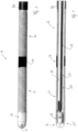
Figur 3 das distale Ende des Ablationsinstruments nachFigur 2 in vergrößerter Seitenansicht, -
Figur 4 das distale Ende des Ablationsinstruments gemäßFigur 3 , jedoch längs geschnitten, -
Figur 5 einen Ausschnitt aus dem Krümmungsbereich des Ablationsinstruments nach denFiguren 1 bis 4 , in schematisierter längsgeschnittener Darstellung, -
Figur 6 einen Ausschnitt aus dem Krümmungsbereich eines Ablationsinstruments nach denFiguren 1 bis 4 , jedoch in abgewandelter Ausführungsform, in schematisierter längsgeschnittener Darstellung. - In
Figur 1 ist eine in ein Endoskop 10 eingesetzte Ablationssonde 11 veranschaulicht, deren distales Ende 12 aus dem Arbeitskanal des Endoskops 10 herausragt. Das proximale Ende 13 der Ablationssonde 11 ist hingegen an ein speisendes Gerät 14 oder einen Geräteverbund angeschlossen, das die Ablationssonde 11 mit Strom, Spannung und Kühlmedium versorgt. - Das Endoskop 10 weist einen länglichen geraden, sich entlang einer Axialrichtung A erstreckenden Schaft 15 auf, dessen distales Ende 16 sich durch ein am proximalen Ende des Schafts 15 vorgesehenes Bedienelement 17, beispielsweise ein Stellrad, Stellhebel oder dergleichen, mehr oder weniger seitlich abwinkeln lässt. In der Nähe dieses Bedienelements 17 weist das Endoskop 10, je nach Anzahl der vorhandenen Arbeitskanäle, ein oder mehrere Anschlüsse 18, 19 auf, über die sich Sonden, Instrumente oder dergleichen, in den jeweiligen Arbeitskanal des Endoskops 10 einführen lassen.
- Das Endoskop 10 ist vorzugsweise zum Arbeiten in engen und verwinkelten Lumen eines Körpers eines Patienten vorgesehen. Es kann z.B. zur Behandlung von Lungengewebe, insbesondere von Tumoren im Lungengewebe, eingesetzt werden. Das distale Ende 16 des Endoskops 10 kann dazu durch entsprechende Betätigung des Bedienelements 17 in eine gestreckte Form gebracht oder auch um einen Winkel von z.B. bis zu 140° oder mehr (150°, 160°) gegen die Axialrichtung A abgewinkelt werden. Dabei können Biegeradien erzeugt werden, die kleiner als 15 mm sind.
-
Figur 2 veranschaulicht die Ablationssonde 11 gesondert anhand deren distalen Endes 12 und des sich proximal daran anschließenden Abschnitts. Dieser Abschnitt enthält unmittelbar anschließend an das distale Ende 12 einen Krümmungsbereich 20, in welchem die Ablationssonde 11 ohne Einfluss äußerer Kräfte gekrümmt ist. Hingegen sind das distale Ende 12 sowie der von dem Krümmungsbereich 20 ausgehend sich bis zu dem proximalen Ende 13 der Sonde erstreckende Abschnitt ohne Einfluss äußerer Kräfte vorzugsweise gerade. Dieser gerade, von dem Krümmungsbereich 20 in proximaler Richtung verlaufende Abschnitt der Ablationssonde 11 legt eine Längsrichtung fest, die mit der Axialrichtung A des Arbeitskanals des Schafts 15 übereinstimmt, wenn das Ablationsinstrument 11 in den Arbeitskanal eingeschoben ist. Der von dem Krümmungsbereich 20 festgelegte Winkel α zwischen dem distalen Ende 12 und der Axialrichtung A ist vorzugsweise etwa halb so groß, wie die von dem distalen Ende 16 des Schafts 15 zu erzielende maximale Angulation. Soll eine maximale Angulation bzw. Abwinklung gegenüber der Axialrichtung A von zum Beispiel 150° erreicht werden, kann der Winkel α vorzugsweise zwischen 30° und 70°, vorzugsweise etwa 50° (+/- 20°) betragen. Somit ist die nötige Verformung des Ablationsinstruments 11 aus der Ruheform in die maximale gestreckte Form oder aus der Ruheform in die maximale abgewinkelte Form jeweils lediglich so gering, dass ein Abknicken der Ablationssonde an der Biegestelle nicht zu befürchten ist. - Die Ablationssonde 11 weist auf ihrem distalen Ende 12 wenigstens eine, vorzugsweise zwei Elektroden 21, 22 auf, die starr oder auch flexibel sein können. Die Elektroden 21, 22 können untereinander gleich ausgebildet sein. Sie weisen in jeder Radialrichtung gleiche elektrische Aktivität auf. Mit anderen Worten, sie erstrecken sich um die gesamte Umfangsrichtung der Ablationssonde 11 herum. Wie insbesondere aus
Figur 3 hervorgeht, können die Elektroden 21, 22 durch einen schraubenförmig gewundenen elektrischen Leiter, beispielsweise einen Draht, gebildet sein. Zwischen den beiden Elektroden 21, 22 kann ein Isolator 23 vorgesehen sein. - Wie
Figur 4 erkennen lässt, sind die beiden Elektroden 21, 22, wie vorzugsweise auch der hülsenförmige Isolator 23, auf einem Schlauch 24 angeordnet, der sich von dem proximalen Ende 13 über die gesamte Länge des Ablationsinstruments 11 durch die Elektroden 21, 22 hindurch bis zu der Instrumentenspitze 25 erstreckt. Die Instrumentenspitze 25 wird durch ein Endstück 26 gebildet, mit dem das von dem Schlauch 24 umschlossene Lumen 27 verschlossen wird. Das Endstück 26 kann zum Beispiel aus Metall bestehen und eine kreuzförmige Spitze aufweisen. Ein Isolatorelement 28 kann das Endstück 26 teilweise überdecken und sich über den Schlauch 24 erstrecken. Das Endstück 26 kann über ein Zugmittel 29, zum Beispiel in Gestalt eines Drahts oder dergleichen, mit dem proximalen Ende des Ablationsinstruments 11 oder einem Bereich des Instruments verbunden sein, der bei einer endoskopischen Anwendung des Ablationsinstruments außerhalb des Endoskops verbleibt. Außerdem kann in dem Lumen 27 eine Fluidleitung angeordnet sein, die von dem proximalen Ende des Ablationsinstruments 11 her ein Kühlmittel bis zu dem distalen Ende 12 führt, um damit die Elektroden 21, 22 zu kühlen. Die Fluidleitung kann insbesondere im distalen Bereich ein Kapillarrohr 30 aufweisen, das auch zur Zugkraftübertragung dienen kann. Das Kapillarrohr 30 kann eine oder mehrere Kühlmittelauslassöffnungen zum Beispiel an seinem distalen Ende oder in seiner Wandung im Bereich der Elektroden 21, 22 aufweisen, um dort eine Kühlwirkung zu erzielen. - Wie
Figur 4 und insbesondereFigur 5 zeigen, ist der Schlauch 24 zumindest abseits seines distalen Endes 12 von einem Mantel 31 umgeben, dessen Innendurchmesser den Außendurchmesser des Schlauchs 24 etwas übersteigt, sodass zwischen dem Schlauch 24 und dem Mantel 31 ein Spalt 32 festgelegt ist. Der Mantel 31 kann sich dabei von dem proximalen Ende 13 bis zu einer der Elektroden 21, 22 erstrecken. Optional kann zwischen dem distalen Ende des Mantels 31 und der Elektrode 22 ein Isolatorring 33 angeordnet sein, der sich an die Elektrode 22 anschließt. - Eine Besonderheit des erfindungsgenmäßen Ablationsinstruments 11 liegt in dem Krümmungsbereich 20, in welchem der Spalt 32 mit einem Kunststoff 34 gefüllt ist. Vorzugsweise erstreckt sich diese Kunststofffüllung jedoch nicht über die gesamte Länge des Ablationsinstruments 11, sondern ist im Wesentlichen auf den Krümmungsbereich 20 beschränkt. Es ist jedoch auch möglich, größere Abschnitte des Spalts 32 oder den gesamten Spalt 32 mit Kunststoff 34 aufzufüllen.
- Anstelle des Isolatorrings 33 kann auch ein Ring 35 aus Metall oder Kunststoff vorgesehen sein, der insbesondere als Zentrierelement dient und aus
Figur 6 hervorgeht. Der Ring 35 weist einen rohrförmigen Fortsatz 36 auf, der sich in den Spalt 32 erstreckt und den Mantel 31 relativ zu dem Schlauch 24 zentriert. Der den Spalt 32 im Krümmungsbereich 20 ausfüllende Kunststoff 34 kann sich zwischen den Mantel 31 und den Fortsatz 36 erstrecken und abdichten. - Der Kunststoff 34 ist vorzugsweise ein aushärtbarer Kunststoff, z.B. ein 2-Komponenten-Kunststoff, der bei der Herstellung des Instruments in flüssiger Form in den Spalt 32, insbesondere im Krümmungsbereich 20, eingebracht wird. Zur Ausbildung des Krümmungsbereichs 20 wird dieser kurz vor dem Einbringen des Kunststoffs oder kurz danach in eine gekrümmte Form überführt, wonach der Kunststoff 34 ausgehärtet wird. Dazu kann das Ablationsinstrument 11 in eine entsprechende Haltevorrichtung eingebracht werden, die dem Ablationsinstrument 11 im Krümmungsbereich 20 eine Bogenform aufzwingt. Nach dem Aushärten des Kunststoffs kann das Ablationsinstrument 11 dieser gebogenen Form entnommen werden, wobei derjenige Bereich des Ablationsinstruments 11, der beim Aushärten des Kunststoffs 34 in gebogener Form gehalten worden ist, den Krümmungsbereich 20 bildet. Die restlichen Abschnitte des Ablationsinstruments 11 liegen jedoch in gestreckter Form vor.
- Das insoweit beschriebene Ablationsinstrument 11 arbeitet wie folgt:
Zum Einsatz am Patienten wird zunächst das Endoskop 10 in den Patienten, beispielsweise in das Bronchialsystem desselben, eingeführt und an der zu behandelnden Stelle platziert. Schon zuvor oder spätestens jetzt wird das Ablationsinstrument 11 über den Anschluss 18 durch den Arbeitskanal des Endoskops 10 an den Operationsort geschoben. Dabei wird das gemäßFigur 2 vorgebogene Ablationsinstrument 11 elastisch in seine gestreckte Form überführt und bis zu dem abgewinkelten Ende 16 des Schafts 15 vorgeschoben. Sobald der Krümmungsbereich 20 des Ablationsinstruments 11 das abgewinkelte distale Ende 16 des Schafts 15 erreicht, vollführt es, infolge seiner Bestrebung in die vorgekrümmte Form zurückzuschnappen, eine axiale Drehbewegung (zumindest sofern es nicht zufällig schon die richtige Drehorientierung um seine Achse A hat). Zugleich mit dem axialen Vorschieben des Ablationsinstruments 11 kann es mit seiner Sondenspitze, d.h. mit seinem Endstück 26 in zu behandelndes Gewebe eindringen bzw. eingestochen werden. Dazu kann gegebenenfalls auch das Endstück 26 mit Spannung und Strom versorgt werden, um das Einstechen in kompaktes Gewebe, beispielsweise Tumorgewebe, zu erleichtern oder kleinere Blutungen zu koagulieren. Die Stromzuführung zu dem Endstück 26 kann über das Zugmittel 29 oder auch über das Kapillarrohr 30 oder einen gesonderten Leiter erfolgen. - Aufgrund der durch den Krümmungsbereich 20 gegebenen Vorbiegung lässt sich das distale Ende 16 des Schafts 15 mit einem sehr engen Biegeradius von zum Beispiel weniger als 15 mm auch auf sehr große stumpfe Winkel gegenüber der Axialrichtung A von zum Beispiel über 145° abwinkeln, ohne dass ein Abknicken des Schlauchs 24 und somit ein Kollaps des Lumens 27 zu befürchten wäre. Zudem wirken der ausgehärtete Kleb- oder Kunststoff 34 sowie der Mantel 31 stützend und verhindern zusätzlich jede Abknicktendenz des Schlauchs 24. Infolgedessen kann das über das Kapillarrohr 30 herbeigeführte Kühlfluid auch in stark anguliertem Zustand des Ablationsinstruments 11 frei durch das Lumen 27 zurück zu dem Gerät 14 oder einem in der Nähe des proximalen Endes 13 vorgesehenen Auslass fließen, ohne zu stauen und somit ohne die Kühlwirkung an den Elektroden 21, 22 zu mindern oder ein Bersten hervorzurufen. Das erfindungsgemäße Instrument gestattet so auch die Behandlung von sonst schwer zugänglichen Tumoren oder sonstigen Gewebepartien, die nur über eine starke Abwinklung des Endes 16 des Endoskops 10 erreichbar sind.
- Das erfindungsgemäße innengekühlte Ablationsinstrument 11 weist im Anschluss an sein distales Ende 12 einen Krümmungsbereich 20 auf, bei welchem das Ablationsinstrument 11 gegen seine Axialrichtung A abgewinkelt ist. Die Größe dieses Winkels ist vorzugsweise auf ein Drittel bis zwei Drittel, vorzugsweise die Hälfte, der maximalen Abwinklung festgelegt. Die maximale Abwinklung kann einen Betrag von 140° deutlich überschreiten. Durch die Vorkrümmung in dem Krümmungsbereich 20 wird ein Abknicken des Schlauchs des Ablationsinstruments und somit eine Beeinträchtigung der Elektrodenkühlung sowie das Auftreten eines hohen Staudruckes wirksam verhindert. Damit gestattet das erfindungsgemäße Ablationsinstrument 11 eine im Vergleich zu vollkommen gestreckten Ablationsinstrumenten freieres und noch stärker an medizinischen Aspekten und Gesichtspunkten ausgerichtetes Arbeiten. Die Behandlungssicherheit für den Patienten wird deutlich erhöht.
-
- 10
- Endoskop
- 11
- Ablationssonde
- 12
- distales Ende der Ablationssonde 11
- 13
- proximales Ende der Ablationssonde 11
- 14
- Gerät zum Betrieb der Ablationssonde 11
- 15
- Schaft des Endoskops 10
- 16
- distales Ende des Schafts 15
- 17
- Bedienelement des Endoskops 10
- 18, 19
- Anschlüsse des Endoskops 10
- A
- Axialrichtung
- 20
- Krümmungsbereich der Ablationssonde 11
- α
- Winkel
- 21, 22
- Elektroden
- 23
- Isolator
- 24
- Schlauch
- 25
- Instrumentenspitze
- 26
- Endstück
- 27
- Lumen
- 28
- Isolator
- 29
- Zugmittel
- 30
- Kapillarrohr
- 31
- Mantel
- 32
- Spalt zwischen Mantel 31 und Schlauch 24
- 33
- Isolator
- 34
- Kunststoff
- 35
- Ring
- 36
- Fortsatz
Claims (15)
- Ablationsinstrument (11), insbesondere zur thermischen Abtötung eines Gewebevolumens durch Bestromung, mit einem flexiblen Schlauch (24), der wenigstens ein Lumen (27) aufweist, das sich von einem proximalen Ende (13) des Schlauchs (24) zu einem distalen Ende (12) des Schlauchs (24) erstreckt,mit mindestens einer Elektrode (21, 22), die an dem distalen Ende (12) des Schlauchs (24) angeordnet ist, undwobei das Ablationsinstrument (11) einen Krümmungsbereich (20) aufweist, in dem der Schlauch (24) ohne auf das Ablationsinstrument (11) einwirkende äußere Kräfte einem Bogen folgend ausgebildet ist.
- Ablationsinstrument nach Anspruch 1, dadurch gekennzeichnet, dass das Lumen (27) an der Spitze des distalen Endes (12) geschlossen ist.
- Ablationsinstrument nach Anspruch 2, dadurch gekennzeichnet, dass zum Verschluss des Schlauchs (24) ein Verschlussstück (26) vorgesehen ist, das mit einem sich von dem distalen Ende (12) in proximaler Richtung erstreckenden Zugmittel (29) verbunden ist.
- Ablationsinstrument nach einem der vorstehenden Ansprüche, dadurch gekennzeichnet, dass in dem Schlauch (24) ein Kapillarkanal angeordnet ist, der eine oder mehrere Mündungen in der Nähe der mindestens einen Elektrode (21) aufweist.
- Ablationsinstrument nach Anspruch 4, dadurch gekennzeichnet, dass der Kapillarkanal in einem sich durch das Lumen erstreckenden Kapillarrohr (30) ausgebildet ist.
- Ablationsinstrument nach einem der vorstehenden Ansprüche, dadurch gekennzeichnet, dass die Elektrode (21) den Schlauch (24) umfassend ausgebildet ist wobei die Elektrode (21) durch einen den Schlauch (24) schraubenförmig umwindenden elektrischen Leiter gebildet ist.
- Ablationsinstrument nach einem der vorstehenden Ansprüche, dadurch gekennzeichnet, dass die Elektrode (22) außerhalb des Krümmungsbereichs (22) angeordnet ist.
- Ablationsinstrument nach einem der vorstehenden Ansprüche, dadurch gekennzeichnet, dass auf dem Schlauch (24) an seinem distalen Ende (12) in dem nicht gekrümmten Bereich desselben wenigstens eine weitere Elektrode (22) angeordnet ist.
- Ablationsinstrument nach Anspruch 8, dadurch gekennzeichnet, dass beide Elektroden (21, 22) in einem Abstand zueinander, jedoch ansonsten gleich ausgebildet sind.
- Ablationsinstrument nach einem der vorstehenden Ansprüche, dadurch gekennzeichnet, dass auf dem Schlauch (24) ein Mantel (31) angeordnet ist.
- Ablationsinstrument nach Anspruch 10, dadurch gekennzeichnet, dass zwischen dem Mantel (31) und dem Schlauch (24) ein Spalt (32) ausgebildet ist.
- Ablationsinstrument nach Anspruch 11, dadurch gekennzeichnet, dass in dem Spalt (32) wenigstens ein elektrischer Leiter angeordnet ist, der sich von der Elektrode (21) in proximaler Richtung erstreckt.
- Ablationsinstrument nach einem der Ansprüche 10 oder 11, dadurch gekennzeichnet, dass der Spalt (32) wenigstens in dem Krümmungsbereich (20) mit einem Kunststoff (34) gefüllt ist.
- Ablationsinstrument nach Anspruch 13, dadurch gekennzeichnet, dass der Kunststoff (34) ein flexibler Kunststoff ist.
- Verfahren zur Herstellung eines Ablationsinstruments nach Anspruch 13, dadurch gekennzeichnet, dass der Kunststoff (34) ein aushärtbarer Kunststoff ist, der in den Spalt (32) eingebracht und das Ablationsinstrument (11) in dem Krümmungsbereich in eine Bogenform überführt und der Kunststoff (34) ausgehärtet wird.
Priority Applications (5)
| Application Number | Priority Date | Filing Date | Title |
|---|---|---|---|
| EP23191383.1A EP4509078A1 (de) | 2023-08-14 | 2023-08-14 | Ablationsinstrument und herstellungsverfahren für dieses |
| JP2024118838A JP2025027433A (ja) | 2023-08-14 | 2024-07-24 | アブレーション器具およびその製造方法 |
| KR1020240103711A KR20250025325A (ko) | 2023-08-14 | 2024-08-05 | 절제 기구 및 그 제조 방법 |
| CN202411096349.XA CN119488350A (zh) | 2023-08-14 | 2024-08-12 | 消融器械及其制造方法 |
| US18/801,988 US20250057592A1 (en) | 2023-08-14 | 2024-08-13 | Ablation instrument and manufacturing method thereof |
Applications Claiming Priority (1)
| Application Number | Priority Date | Filing Date | Title |
|---|---|---|---|
| EP23191383.1A EP4509078A1 (de) | 2023-08-14 | 2023-08-14 | Ablationsinstrument und herstellungsverfahren für dieses |
Publications (1)
| Publication Number | Publication Date |
|---|---|
| EP4509078A1 true EP4509078A1 (de) | 2025-02-19 |
Family
ID=87571776
Family Applications (1)
| Application Number | Title | Priority Date | Filing Date |
|---|---|---|---|
| EP23191383.1A Pending EP4509078A1 (de) | 2023-08-14 | 2023-08-14 | Ablationsinstrument und herstellungsverfahren für dieses |
Country Status (5)
| Country | Link |
|---|---|
| US (1) | US20250057592A1 (de) |
| EP (1) | EP4509078A1 (de) |
| JP (1) | JP2025027433A (de) |
| KR (1) | KR20250025325A (de) |
| CN (1) | CN119488350A (de) |
Citations (12)
| Publication number | Priority date | Publication date | Assignee | Title |
|---|---|---|---|---|
| US2022065A (en) | 1932-07-07 | 1935-11-26 | Frederick C Wappler | Therapeutic applicator device |
| US4474174A (en) | 1979-05-21 | 1984-10-02 | American Hospital Supply Corporation | Surgical instrument for an endoscope |
| EP0536440B1 (de) | 1991-10-11 | 1997-05-28 | Erbe Elektromedizin GmbH | Instrument für die Hochfrequenzchirurgie zum Schneiden oder Koagulieren |
| WO1998026724A1 (en) * | 1996-12-19 | 1998-06-25 | Ep Technologies, Inc. | Branched structures for supporting multiple electrode elements |
| US6017340A (en) | 1994-10-03 | 2000-01-25 | Wiltek Medical Inc. | Pre-curved wire guided papillotome having a shape memory tip for controlled bending and orientation |
| EP1076523A1 (de) | 1998-04-28 | 2001-02-21 | Nahum S. Goldberg | Verfahren und vorrichtung zur trans-lumenalen hochfrequenz-ablation durch ein endoskop |
| EP0947171B1 (de) | 1998-03-31 | 2003-07-23 | Ferton Holding S.A. | Flexible Metallsonde zur Verwendung bei der intrakorporalen Stosswellen-Lithotripsie |
| WO2005065550A2 (en) * | 2003-12-29 | 2005-07-21 | Boston Scientific Limited | Selectively light curable support members for medical devices |
| WO2005079901A1 (en) * | 2004-02-17 | 2005-09-01 | Boston Scientific Limited | Endoscopic multi-lumen devices and related methods of use |
| WO2007035554A1 (en) * | 2005-09-16 | 2007-03-29 | Biosense Webster, Inc. | Catheter with flexible pre-shaped tip section |
| US20070250040A1 (en) * | 2006-04-19 | 2007-10-25 | Medtronic Vascular, Inc. | Composite laminated catheter with flexible segment and method of making same |
| EP3788974A1 (de) | 2019-09-05 | 2021-03-10 | Erbe Elektromedizin GmbH | Ablationssonde |
Family Cites Families (1)
| Publication number | Priority date | Publication date | Assignee | Title |
|---|---|---|---|---|
| EP3191003B1 (de) * | 2015-01-07 | 2021-09-29 | St. Jude Medical, Cardiology Division, Inc. | Ablationskatheter mit elektroden |
-
2023
- 2023-08-14 EP EP23191383.1A patent/EP4509078A1/de active Pending
-
2024
- 2024-07-24 JP JP2024118838A patent/JP2025027433A/ja active Pending
- 2024-08-05 KR KR1020240103711A patent/KR20250025325A/ko active Pending
- 2024-08-12 CN CN202411096349.XA patent/CN119488350A/zh active Pending
- 2024-08-13 US US18/801,988 patent/US20250057592A1/en active Pending
Patent Citations (12)
| Publication number | Priority date | Publication date | Assignee | Title |
|---|---|---|---|---|
| US2022065A (en) | 1932-07-07 | 1935-11-26 | Frederick C Wappler | Therapeutic applicator device |
| US4474174A (en) | 1979-05-21 | 1984-10-02 | American Hospital Supply Corporation | Surgical instrument for an endoscope |
| EP0536440B1 (de) | 1991-10-11 | 1997-05-28 | Erbe Elektromedizin GmbH | Instrument für die Hochfrequenzchirurgie zum Schneiden oder Koagulieren |
| US6017340A (en) | 1994-10-03 | 2000-01-25 | Wiltek Medical Inc. | Pre-curved wire guided papillotome having a shape memory tip for controlled bending and orientation |
| WO1998026724A1 (en) * | 1996-12-19 | 1998-06-25 | Ep Technologies, Inc. | Branched structures for supporting multiple electrode elements |
| EP0947171B1 (de) | 1998-03-31 | 2003-07-23 | Ferton Holding S.A. | Flexible Metallsonde zur Verwendung bei der intrakorporalen Stosswellen-Lithotripsie |
| EP1076523A1 (de) | 1998-04-28 | 2001-02-21 | Nahum S. Goldberg | Verfahren und vorrichtung zur trans-lumenalen hochfrequenz-ablation durch ein endoskop |
| WO2005065550A2 (en) * | 2003-12-29 | 2005-07-21 | Boston Scientific Limited | Selectively light curable support members for medical devices |
| WO2005079901A1 (en) * | 2004-02-17 | 2005-09-01 | Boston Scientific Limited | Endoscopic multi-lumen devices and related methods of use |
| WO2007035554A1 (en) * | 2005-09-16 | 2007-03-29 | Biosense Webster, Inc. | Catheter with flexible pre-shaped tip section |
| US20070250040A1 (en) * | 2006-04-19 | 2007-10-25 | Medtronic Vascular, Inc. | Composite laminated catheter with flexible segment and method of making same |
| EP3788974A1 (de) | 2019-09-05 | 2021-03-10 | Erbe Elektromedizin GmbH | Ablationssonde |
Also Published As
| Publication number | Publication date |
|---|---|
| CN119488350A (zh) | 2025-02-21 |
| US20250057592A1 (en) | 2025-02-20 |
| JP2025027433A (ja) | 2025-02-27 |
| KR20250025325A (ko) | 2025-02-21 |
Similar Documents
| Publication | Publication Date | Title |
|---|---|---|
| DE19847852B4 (de) | Behandlungsinstrument für ein Endoskop | |
| DE69417206T2 (de) | Führbare medizinische Sonde mit Stilette | |
| EP2956071B1 (de) | Set für die periphere nervenblockade | |
| EP1849493B1 (de) | Katheterset für die epidurale oder periphere Nervenblockade | |
| DE3245814C2 (de) | Hochfrequenz-chirurgische Vorrichtung in einem Endoskop | |
| EP2083732B1 (de) | Biegeweicher katheter zur hochfrequenztherapie von biologischem gewebe | |
| DE2009093B2 (de) | Katheter mit einem elektrischen letier | |
| EP3453352B1 (de) | Medizinisches instrument zum abtragen von gewebe mittels einer hf-elektrode mit der funktion einer kontrollierten distalen winkelausrichtung | |
| DE202008018476U1 (de) | Einsatzsystem und Führung zur Behandlung einer Zielgeweberegion | |
| DE112014007043T5 (de) | Endoskophülle und Endoskop-Injektionspositioniervorrichtung | |
| DE102018002356A1 (de) | Instrumenten-Set und Verfahren zur Durchführung von Operationen an Wirbeln oder Knochen | |
| EP1862139A2 (de) | Therapiegerät | |
| WO2015022103A1 (de) | Führungskatheter mit stabilisierungsmechanismus und verfahren zum einführen eines führungskatheters | |
| WO2004103195A2 (de) | Instrument zur unipolaren ablation von herzgewebe | |
| EP1924313B1 (de) | Medizinisches instrument | |
| EP2641554B1 (de) | Endoskopisches Chirurgieinstrument | |
| EP1646323B1 (de) | Chirurgische sonde | |
| EP4509078A1 (de) | Ablationsinstrument und herstellungsverfahren für dieses | |
| DE102021109175A1 (de) | Elektrodeninstrument, chirurgisches Handgerät und deren Herstellungsverfahren | |
| EP3471642B1 (de) | Chirurgisches instrument für die elektrotomie und werkzeug dafür | |
| DE102019212197A1 (de) | Lichtapplikatorsystem | |
| EP4159147B1 (de) | Einrichtung zur gewebebehandlung | |
| DE112016003790B4 (de) | Elektrochirurgische Vorrichtung | |
| DE102019212203B4 (de) | Lichtapplikatorsystem | |
| EP4349287A1 (de) | Ablationsinstrument |
Legal Events
| Date | Code | Title | Description |
|---|---|---|---|
| PUAI | Public reference made under article 153(3) epc to a published international application that has entered the european phase |
Free format text: ORIGINAL CODE: 0009012 |
|
| STAA | Information on the status of an ep patent application or granted ep patent |
Free format text: STATUS: THE APPLICATION HAS BEEN PUBLISHED |
|
| AK | Designated contracting states |
Kind code of ref document: A1 Designated state(s): AL AT BE BG CH CY CZ DE DK EE ES FI FR GB GR HR HU IE IS IT LI LT LU LV MC ME MK MT NL NO PL PT RO RS SE SI SK SM TR |
|
| STAA | Information on the status of an ep patent application or granted ep patent |
Free format text: STATUS: REQUEST FOR EXAMINATION WAS MADE |
|
| 17P | Request for examination filed |
Effective date: 20250717 |