EP3148718B1 - Device for the maintenance of tanks and cisterns designed to contain dangerous products - Google Patents
Device for the maintenance of tanks and cisterns designed to contain dangerous products Download PDFInfo
- Publication number
- EP3148718B1 EP3148718B1 EP15732372.6A EP15732372A EP3148718B1 EP 3148718 B1 EP3148718 B1 EP 3148718B1 EP 15732372 A EP15732372 A EP 15732372A EP 3148718 B1 EP3148718 B1 EP 3148718B1
- Authority
- EP
- European Patent Office
- Prior art keywords
- tool
- tank
- carriage
- articulated
- arm
- Prior art date
- Legal status (The legal status is an assumption and is not a legal conclusion. Google has not performed a legal analysis and makes no representation as to the accuracy of the status listed.)
- Active
Links
Images




Classifications
-
- B—PERFORMING OPERATIONS; TRANSPORTING
- B05—SPRAYING OR ATOMISING IN GENERAL; APPLYING FLUENT MATERIALS TO SURFACES, IN GENERAL
- B05B—SPRAYING APPARATUS; ATOMISING APPARATUS; NOZZLES
- B05B15/00—Details of spraying plant or spraying apparatus not otherwise provided for; Accessories
- B05B15/60—Arrangements for mounting, supporting or holding spraying apparatus
- B05B15/68—Arrangements for adjusting the position of spray heads
-
- B—PERFORMING OPERATIONS; TRANSPORTING
- B08—CLEANING
- B08B—CLEANING IN GENERAL; PREVENTION OF FOULING IN GENERAL
- B08B9/00—Cleaning hollow articles by methods or apparatus specially adapted thereto
- B08B9/08—Cleaning containers, e.g. tanks
- B08B9/093—Cleaning containers, e.g. tanks by the force of jets or sprays
-
- B—PERFORMING OPERATIONS; TRANSPORTING
- B08—CLEANING
- B08B—CLEANING IN GENERAL; PREVENTION OF FOULING IN GENERAL
- B08B9/00—Cleaning hollow articles by methods or apparatus specially adapted thereto
- B08B9/02—Cleaning pipes or tubes or systems of pipes or tubes
- B08B9/027—Cleaning the internal surfaces; Removal of blockages
- B08B9/04—Cleaning the internal surfaces; Removal of blockages using cleaning devices introduced into and moved along the pipes
- B08B9/049—Cleaning the internal surfaces; Removal of blockages using cleaning devices introduced into and moved along the pipes having self-contained propelling means for moving the cleaning devices along the pipes, i.e. self-propelled
-
- B—PERFORMING OPERATIONS; TRANSPORTING
- B05—SPRAYING OR ATOMISING IN GENERAL; APPLYING FLUENT MATERIALS TO SURFACES, IN GENERAL
- B05B—SPRAYING APPARATUS; ATOMISING APPARATUS; NOZZLES
- B05B13/00—Machines or plants for applying liquids or other fluent materials to surfaces of objects or other work by spraying, not covered by groups B05B1/00 - B05B11/00
- B05B13/005—Machines or plants for applying liquids or other fluent materials to surfaces of objects or other work by spraying, not covered by groups B05B1/00 - B05B11/00 mounted on vehicles or designed to apply a liquid on a very large surface, e.g. on the road, on the surface of large containers
-
- B—PERFORMING OPERATIONS; TRANSPORTING
- B05—SPRAYING OR ATOMISING IN GENERAL; APPLYING FLUENT MATERIALS TO SURFACES, IN GENERAL
- B05B—SPRAYING APPARATUS; ATOMISING APPARATUS; NOZZLES
- B05B13/00—Machines or plants for applying liquids or other fluent materials to surfaces of objects or other work by spraying, not covered by groups B05B1/00 - B05B11/00
- B05B13/06—Machines or plants for applying liquids or other fluent materials to surfaces of objects or other work by spraying, not covered by groups B05B1/00 - B05B11/00 specially designed for treating the inside of hollow bodies
- B05B13/0627—Arrangements of nozzles or spray heads specially adapted for treating the inside of hollow bodies
-
- B—PERFORMING OPERATIONS; TRANSPORTING
- B05—SPRAYING OR ATOMISING IN GENERAL; APPLYING FLUENT MATERIALS TO SURFACES, IN GENERAL
- B05B—SPRAYING APPARATUS; ATOMISING APPARATUS; NOZZLES
- B05B15/00—Details of spraying plant or spraying apparatus not otherwise provided for; Accessories
- B05B15/60—Arrangements for mounting, supporting or holding spraying apparatus
- B05B15/62—Arrangements for supporting spraying apparatus, e.g. suction cups
- B05B15/628—Arrangements for supporting spraying apparatus, e.g. suction cups of variable length
-
- B—PERFORMING OPERATIONS; TRANSPORTING
- B08—CLEANING
- B08B—CLEANING IN GENERAL; PREVENTION OF FOULING IN GENERAL
- B08B9/00—Cleaning hollow articles by methods or apparatus specially adapted thereto
- B08B9/08—Cleaning containers, e.g. tanks
- B08B9/087—Cleaning containers, e.g. tanks by methods involving the use of tools, e.g. brushes, scrapers
Definitions
- This invention relates to a device designed to perform maintenance operations on the inside surfaces of tanks used to hold hazardous and non-hazardous products.
- this invention relates to a device designed to perform maintenance operations on tanks which extends the operation of the maintenance carriages used up to now to allow the operation to be adapted to the increased dimensions of the spaces involved in the operation.
- the device according to the invention defined in appended claim 1 is mounted on a self-propelled carriage and comprises a system of articulated telescopic and rotary elements hinged to each other, carrying one or more tools, which allows movement towards the surfaces to be treated by the tool, in such a way as to always operate at the optimum distance.
- the assembly of elements is moved by the same console used for moving the self-propelled support carriage and it becomes to all intents and purposes an integral part.
- the device according to the invention aims, on the one hand, to increase the effectiveness of the traditional carriages for the treatment of tanks, especially those with a large capacity, and, on the other hand, to increase the versatility of use, adopting a system of interchangeable tools which allow, for example, washing, spraying of paint or gelcoats, measurement of thicknesses or sandblasting, all at a distance close to the surface to be treated.
- This invention is applicable and finds its main use in all the applications which require maintenance, inspection and, in general, control operations for the inside walls of tanks and structures containing fuels and other solid or liquid products.
- this invention can be applied for the maintenance of tanks where for reasons of safety the access of personnel inside is not allowed (no man entry), and where access normally consists of an opening of very limited dimensions, such as, for example, a manhole.
- tanks in general and more specifically those for holding fuels are subject over time to deterioration, which implies regular maintenance activities on the inside walls, such as cleaning, restoring and painting, and the implementation of non-destructive investigations by means of suitable tests, in order to check the condition.
- Document US 2004/0099288A1 discloses an apparatus for scarifying the interior surface of a sewer pipe.
- the apparatus consists of a chassis, with an outer frame coupled to the chassis and an inner frame slidably coupled to the outer frame
- Two extendable arms are attached to opposite sides of the inner frame.
- Each arm has a nozzle assembly mounted on the end, each nozzle assembly having a plurality of fluid jets for spray water onto the interior surface of the pipeline.
- the nozzle assembly may be pivotally mounted to allow for greater control of the fluid jets.
- the apparatus further includes a propulsion system for movement of the apparatus along the pipeline.
- Document DE G9307652.5 U1 also describes a movable device for cleaning tanks for the sprouting or drying of grain or fruit or vegetables.
- Document DE 29603291 U1 relates to a vehicle for performing inspections (and it is for this reason provided with a video camera) inside pipes equipped with a worm screw mechanism for moving the movable arm of the carriage.
- None of these vehicles are designed to be inserted through a tank opening of limited size, in particular a manhole, for access which is not recommended for personnel for safety reasons, and they are not designed to perform different operations inside the tank, placing one or more tools or heads immediately next to the inside wall of the tank.
- US 5 081 800 A discloses a vehicle with a manipulator arm provided with a blasting nozzle at its end and proximity detectors placed close to it in order to allow automatic control of the movements of the nozzle.
- the aim of this invention is to provide a device to perform maintenance operations on tanks, in particular for holding hazardous products, which is able to overcome or at least reduce the above-mentioned drawbacks.
- the invention also aims to provide a device designed for maintenance operations on tanks which is simple to produce but extremely practical and functional to use, having components which are able to move the tools towards the walls to be treated irrespective of the dimensions of the tank itself.
- This mechanical arm allows particularly effective operations to be performed, even in zones which are difficult to treat, such as, for example, the ceiling of tanks, even large ones, as it is able to move the tools towards the inner walls of the areas to be treated.
- a device 10 is positioned inside a cylindrical tank 20 with a horizontal axis provided with a manhole opening 11, and it substantially consists of an articulated arm 31 applied on a carriage 32 driven by a pneumatic or hydraulic motor, and generally moved by tracks or the like, which can be connected by suitable wiring 33 to a control panel 34 located outside the tank.
- the arm 31 consists of a series of elements which will be described in more detail below, and it can be operated by means of the same control panel 34 of the carriage 32 and it is in fact an integral part of it.
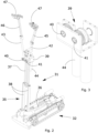
- Figure 2 are highlights the constructional features of the articulated arm 31.
- the arm 31 comprises a tower 35 hinged on the carriage 32.
- the tower 35 is able to rotate by 90° to the horizontal and move at right angles to it, adopting a substantially vertical position, using a piston 36.
- the tower 35 is equipped with a telescopic device 37 which by means of pistons 38 is able to raise up to twice its height.
- a telescopic device 37 which by means of pistons 38 is able to raise up to twice its height.
- the telescopic device 37 allows a gear unit 39 to reach the centre of the tank.
- the above-mentioned gear unit 39 is mounted on the telescopic device 37, and on the axes of rotation 40, 41 of the unit are mounted telescopic rods 42, 43 which can rotate on the axis of the gears by means of a motor 44 which places the rods 42, 43 in counter-rotation respectively about the pivots formed by the axes 40, 41.
- Each telescopic rod 42, 43 is provided with respective telescopic devices 45, 46 at the top of each of which is applied a tool 47, which in the case illustrated in Figure 2 is represented by a series of nozzles for performing high pressure washing.
- sliding members 45 and 46 make it possible to increase the operating distance covered by the articulated arms 42 and 43.
- Figure 3 shows a detail of the kinematic unit 39 comprising gears for rotating the telescopic rods 42 and 43 applied on the rotational pins 40 and 41.
- Figures 4 to 7 the arm 31 and carriage 32 assembly is on the bottom of the tank 10.
- Figure 4 shows the articulated arm 31 in the closed position immediately after having been lowered through the manhole 11
- Figure 5 shows the arm with the tower 35 in the vertical position
- Figure 6 shows the tower 35 raised and the telescopic device 37 lifted.
- the rods 42, 43 are rotated and the telescopic devices are open, allowing the tools to move close to the walls to be treated.
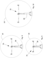
- Figures 8 to 10 show all the movements which can be performed by the articulated arm 31 and, as may be noted, all the telescopic devices of the same articulated arm may be extended to the distance necessary for the size of the tank to be treated, and the set of mutual translational and rotational movements which the various components of the arm 31 can perform in combination with each other allows an increase in operational efficiency, guaranteeing the optimum working distance with variations in the diameter of the tank.
- FIGS. 1-10 show tanks of various diameters comprising the carriage 32 and the articulated arm 31, which may be configured to optimise the working distance of the respective tool from the surfaces to be treated.
- the set of elements which constitute the invention that is to say, the arm 50 mounted on the carriage 51, can be operated by the same control panel 52 connected to the carriage 51 by wiring 53.
- Figure 12 highlights the distinctive constructional feature of the invention, and it may be noted that in this second embodiment the arm 50 is installed on a base 54 which may rotate through 360° relative to a vertical axis, the base 54 being fixed by a rack 55 to the carriage 51.
- the tower 57 is in this case hinged on the base 54 and, by means of a motor 59 connected to a worm screw 60, rotates relative to the pivot 58 through 90° to move to a vertical position.
- a telescopic device 61 which by means of a motor 62 rises to twice the height of the tower 57 moving, in the case of cylindrical tanks with a horizontal axis, the box gear 63 close to the centre of the tank.
- a gear box 63 similar to the box 39 described above, which, by means of a motor 64 rotates a rod 65 equipped with the telescopic device 66 at the top of which is fixed a tool 67.
- a feeler device 68 connected to the control panel which makes it possible to automatically adjust the length of the telescopic device 66 for moving the tool 67 to the optimum working distance or in contact with the surfaces to be treated.
- the feeler device is also present in all embodiments of the device according to the invention.
- Figures 13 to 17 show in sequence the opening movements of the arm 50 during its operation.
- Figure 13 shows the assembly made up of the arm 50 and carriage 51 located on the bottom of the tank 30 in a closed position immediately after having been lowered into the tank through the manhole.
- Figure 14 shows the arm with the tower 57 in the vertical position and Figure 15 shows the arm rotated by 90° with respect to the carriage 51.
- Figures 18 to 20 show tanks of various diameters comprising inside them the carriage 51 comprising the articulated movable arm 50 according to the second embodiment of the invention, and again in this case it may be noted that the articulated arm 50 of the carriage unit according to the invention may be configured in various ways according to the dimensions of the tank so as to optimise the working distance of the respective tool from the surfaces to be treated.
Landscapes
- Engineering & Computer Science (AREA)
- Mechanical Engineering (AREA)
- Cleaning In General (AREA)
- Working Measures On Existing Buildindgs (AREA)
- Filling Or Discharging Of Gas Storage Vessels (AREA)
- Spray Control Apparatus (AREA)
Priority Applications (1)
| Application Number | Priority Date | Filing Date | Title |
|---|---|---|---|
| SI201531972T SI3148718T1 (sl) | 2014-05-30 | 2015-05-15 | Naprava za vzdrževanje rezervoarjev in cistern, namenjenih za shranjevanje nevarnih izdelkov |
Applications Claiming Priority (2)
| Application Number | Priority Date | Filing Date | Title |
|---|---|---|---|
| ITVR20140159 | 2014-05-30 | ||
| PCT/IB2015/053598 WO2015181670A1 (en) | 2014-05-30 | 2015-05-15 | Device for the maintenance of tanks and cisterns designed to contain dangerous products |
Publications (2)
| Publication Number | Publication Date |
|---|---|
| EP3148718A1 EP3148718A1 (en) | 2017-04-05 |
| EP3148718B1 true EP3148718B1 (en) | 2023-07-19 |
Family
ID=51230122
Family Applications (1)
| Application Number | Title | Priority Date | Filing Date |
|---|---|---|---|
| EP15732372.6A Active EP3148718B1 (en) | 2014-05-30 | 2015-05-15 | Device for the maintenance of tanks and cisterns designed to contain dangerous products |
Country Status (9)
| Country | Link |
|---|---|
| EP (1) | EP3148718B1 (da) |
| CN (1) | CN105916601A (da) |
| DK (1) | DK3148718T3 (da) |
| ES (1) | ES2959421T3 (da) |
| FI (1) | FI3148718T3 (da) |
| HU (1) | HUE063963T2 (da) |
| PL (1) | PL3148718T3 (da) |
| SI (1) | SI3148718T1 (da) |
| WO (1) | WO2015181670A1 (da) |
Families Citing this family (6)
| Publication number | Priority date | Publication date | Assignee | Title |
|---|---|---|---|---|
| CN106078761B (zh) * | 2016-07-18 | 2018-05-01 | 冯广义 | 一种可反馈式电缆维修机器人 |
| CN107088486A (zh) * | 2017-04-21 | 2017-08-25 | 成都大漠石油技术有限公司 | 将防锈液喷涂在油桶内壁的机构 |
| CN110918324B (zh) * | 2019-12-19 | 2020-11-27 | 乐清市凡山电器有限公司 | 一种基于视觉伺服的多枪混控喷漆机器人 |
| CN111036460B (zh) * | 2019-12-19 | 2024-11-19 | 华能延安发电有限公司 | 火力发电厂脱硫吸收塔智能防腐材料喷涂系统 |
| CN111515200B (zh) * | 2020-04-15 | 2024-08-23 | 四川义德智慧科技有限公司 | 一种水泥清库装置 |
| CN111673706A (zh) * | 2020-06-04 | 2020-09-18 | 宣城智新机电科技有限责任公司 | 一种基于x射线机的双臂双机轮式行走探伤机器人 |
Family Cites Families (10)
| Publication number | Priority date | Publication date | Assignee | Title |
|---|---|---|---|---|
| EP0365921B1 (de) * | 1988-10-25 | 1992-03-11 | HEINRICH SCHLICK GmbH | Vorrichtung zum Befahren von geschlossenen Kanälen |
| US5205174A (en) * | 1991-05-24 | 1993-04-27 | Silverman Eugene B | Scavenger submersible visual and acoustical tank inspection system and method |
| DE9307652U1 (de) | 1993-05-19 | 1993-07-15 | Kneisel & Heess GmbH, 6840 Lampertheim | Mobiler Reinigungswagen zum Säubern von, während des Reinigungsvorganges schlecht zugänglichen Einrichtungen |
| DE29603291U1 (de) | 1996-02-23 | 1997-02-06 | JT Elektronik GmbH, 88131 Lindau | Elektrische Höhen- und Neigungsverstellung |
| US20020179123A1 (en) * | 2001-05-31 | 2002-12-05 | Charles Toward | Fluidized cleaning and scarification apparatus and method |
| DE10162477B4 (de) * | 2001-12-19 | 2007-03-29 | Framatome Anp Gmbh | Vorrichtung zur Reinigung eines Behälters für radioaktive Reststoffe |
| CA2412691C (en) | 2002-11-25 | 2008-02-26 | Mac & Mac Hydrodemolition Inc. | Scarifying apparatus for interior surface of pipeline |
| CN201720225U (zh) * | 2010-07-16 | 2011-01-26 | 湖南大学 | 中央空调风管清扫机器人多自由度立体毛刷清扫装置 |
| CN103372561A (zh) * | 2012-04-17 | 2013-10-30 | 中国石油化工股份有限公司 | 一种油罐清洗系统及方法和应用 |
| CN102764750B (zh) * | 2012-08-12 | 2014-02-26 | 周利坤 | 一种油罐清洗机器人 |
-
2015
- 2015-05-15 ES ES15732372T patent/ES2959421T3/es active Active
- 2015-05-15 FI FIEP15732372.6T patent/FI3148718T3/fi active
- 2015-05-15 SI SI201531972T patent/SI3148718T1/sl unknown
- 2015-05-15 CN CN201580004644.0A patent/CN105916601A/zh active Pending
- 2015-05-15 WO PCT/IB2015/053598 patent/WO2015181670A1/en not_active Ceased
- 2015-05-15 EP EP15732372.6A patent/EP3148718B1/en active Active
- 2015-05-15 HU HUE15732372A patent/HUE063963T2/hu unknown
- 2015-05-15 PL PL15732372.6T patent/PL3148718T3/pl unknown
- 2015-05-15 DK DK15732372.6T patent/DK3148718T3/da active
Also Published As
| Publication number | Publication date |
|---|---|
| HUE063963T2 (hu) | 2024-02-28 |
| CN105916601A (zh) | 2016-08-31 |
| DK3148718T3 (da) | 2023-10-23 |
| ES2959421T3 (es) | 2024-02-26 |
| PL3148718T3 (pl) | 2023-12-27 |
| SI3148718T1 (sl) | 2024-01-31 |
| WO2015181670A1 (en) | 2015-12-03 |
| EP3148718A1 (en) | 2017-04-05 |
| FI3148718T3 (fi) | 2023-10-18 |
Similar Documents
| Publication | Publication Date | Title |
|---|---|---|
| WO2015181670A1 (en) | Device for the maintenance of tanks and cisterns designed to contain dangerous products | |
| US5518553A (en) | Storage tank cleaning and stripping apparatus and method | |
| CA3070131C (en) | System for laser treating a pipe surface | |
| EP3242753B1 (en) | High pressure waterblasting nozzle manipulator apparatus | |
| US7320329B2 (en) | Remotely operated cleaning device, especially suitable for storage tanks on vessels | |
| US3645452A (en) | Tank cleaner | |
| US5642745A (en) | Tank cleaning system using collapsible robotic tank entry vehicle | |
| US11440064B2 (en) | Systems and methods for tank cleaning | |
| US5718382A (en) | Apparatus for cleaning vessels | |
| JP6858250B2 (ja) | 石油精製・化学反応器等の容器から触媒等の物質を除去するための装置 | |
| US7261109B2 (en) | Remotely operated cleaning device, especially suitable for storage tanks on vessels | |
| US9919333B2 (en) | High pressure waterblasting nozzle manipulator apparatus | |
| KR101516689B1 (ko) | 보수 장치 | |
| US20210308728A1 (en) | Apparatuses, systems, and methods for cleaning | |
| EP3643414B1 (en) | An ultra-high-pressure water jetting (uhpwj) hydro-blasting cleaning system for surfaces | |
| KR20150067120A (ko) | 유지 보수 장치 | |
| CN103328320B (zh) | 维护装置 | |
| US9492907B2 (en) | Surface media blasting system and method | |
| KR20220101623A (ko) | 피클링 및/또는 페인트 코팅에 의한 보수 및/또는 넓은 표면 및/또는 높은 높이의 벽의 검사를 위한 로봇, 관련 작동 방법, 및 선박 선체의 피클링 및 페인팅에 적용 | |
| EA030217B1 (ru) | Многофункциональный робот для проведения технического обслуживания в тесных пространствах металлических конструкций | |
| US9656308B2 (en) | Systems and processes for cleaning tanker truck interiors | |
| US11413666B1 (en) | Vertical travel robotic tank cleaning system | |
| CA3124089A1 (en) | Cavity cleaning and coating system | |
| USRE27612E (en) | Jet spray tank cleaner | |
| GB2242887A (en) | Manoeuvrable work platform assembly |
Legal Events
| Date | Code | Title | Description |
|---|---|---|---|
| STAA | Information on the status of an ep patent application or granted ep patent |
Free format text: STATUS: THE INTERNATIONAL PUBLICATION HAS BEEN MADE |
|
| PUAI | Public reference made under article 153(3) epc to a published international application that has entered the european phase |
Free format text: ORIGINAL CODE: 0009012 |
|
| STAA | Information on the status of an ep patent application or granted ep patent |
Free format text: STATUS: REQUEST FOR EXAMINATION WAS MADE |
|
| 17P | Request for examination filed |
Effective date: 20160526 |
|
| AK | Designated contracting states |
Kind code of ref document: A1 Designated state(s): AL AT BE BG CH CY CZ DE DK EE ES FI FR GB GR HR HU IE IS IT LI LT LU LV MC MK MT NL NO PL PT RO RS SE SI SK SM TR |
|
| AX | Request for extension of the european patent |
Extension state: BA ME |
|
| DAV | Request for validation of the european patent (deleted) | ||
| DAX | Request for extension of the european patent (deleted) | ||
| STAA | Information on the status of an ep patent application or granted ep patent |
Free format text: STATUS: EXAMINATION IS IN PROGRESS |
|
| 17Q | First examination report despatched |
Effective date: 20210615 |
|
| GRAP | Despatch of communication of intention to grant a patent |
Free format text: ORIGINAL CODE: EPIDOSNIGR1 |
|
| STAA | Information on the status of an ep patent application or granted ep patent |
Free format text: STATUS: GRANT OF PATENT IS INTENDED |
|
| RIC1 | Information provided on ipc code assigned before grant |
Ipc: B05B 15/68 20180101ALI20230118BHEP Ipc: B05B 13/06 20060101ALI20230118BHEP Ipc: B05B 15/628 20180101ALI20230118BHEP Ipc: B05B 13/00 20060101ALI20230118BHEP Ipc: B08B 9/049 20060101ALI20230118BHEP Ipc: B05B 13/04 20060101ALI20230118BHEP Ipc: B08B 9/087 20060101ALI20230118BHEP Ipc: B08B 9/093 20060101AFI20230118BHEP |
|
| INTG | Intention to grant announced |
Effective date: 20230213 |
|
| GRAS | Grant fee paid |
Free format text: ORIGINAL CODE: EPIDOSNIGR3 |
|
| GRAA | (expected) grant |
Free format text: ORIGINAL CODE: 0009210 |
|
| STAA | Information on the status of an ep patent application or granted ep patent |
Free format text: STATUS: THE PATENT HAS BEEN GRANTED |
|
| AK | Designated contracting states |
Kind code of ref document: B1 Designated state(s): AL AT BE BG CH CY CZ DE DK EE ES FI FR GB GR HR HU IE IS IT LI LT LU LV MC MK MT NL NO PL PT RO RS SE SI SK SM TR |
|
| REG | Reference to a national code |
Ref country code: GB Ref legal event code: FG4D |
|
| REG | Reference to a national code |
Ref country code: CH Ref legal event code: EP |
|
| REG | Reference to a national code |
Ref country code: DE Ref legal event code: R096 Ref document number: 602015084641 Country of ref document: DE |
|
| REG | Reference to a national code |
Ref country code: IE Ref legal event code: FG4D |
|
| REG | Reference to a national code |
Ref country code: FI Ref legal event code: FGE |
|
| REG | Reference to a national code |
Ref country code: DK Ref legal event code: T3 Effective date: 20231018 |
|
| REG | Reference to a national code |
Ref country code: NL Ref legal event code: FP |
|
| REG | Reference to a national code |
Ref country code: LT Ref legal event code: MG9D |
|
| REG | Reference to a national code |
Ref country code: NO Ref legal event code: T2 Effective date: 20230719 |
|
| P01 | Opt-out of the competence of the unified patent court (upc) registered |
Effective date: 20231113 |
|
| PG25 | Lapsed in a contracting state [announced via postgrant information from national office to epo] |
Ref country code: GR Free format text: LAPSE BECAUSE OF FAILURE TO SUBMIT A TRANSLATION OF THE DESCRIPTION OR TO PAY THE FEE WITHIN THE PRESCRIBED TIME-LIMIT Effective date: 20231020 |
|
| REG | Reference to a national code |
Ref country code: SK Ref legal event code: T3 Ref document number: E 42613 Country of ref document: SK |
|
| PG25 | Lapsed in a contracting state [announced via postgrant information from national office to epo] |
Ref country code: SE Free format text: LAPSE BECAUSE OF FAILURE TO SUBMIT A TRANSLATION OF THE DESCRIPTION OR TO PAY THE FEE WITHIN THE PRESCRIBED TIME-LIMIT Effective date: 20230719 Ref country code: RS Free format text: LAPSE BECAUSE OF FAILURE TO SUBMIT A TRANSLATION OF THE DESCRIPTION OR TO PAY THE FEE WITHIN THE PRESCRIBED TIME-LIMIT Effective date: 20230719 Ref country code: PT Free format text: LAPSE BECAUSE OF FAILURE TO SUBMIT A TRANSLATION OF THE DESCRIPTION OR TO PAY THE FEE WITHIN THE PRESCRIBED TIME-LIMIT Effective date: 20231120 Ref country code: LV Free format text: LAPSE BECAUSE OF FAILURE TO SUBMIT A TRANSLATION OF THE DESCRIPTION OR TO PAY THE FEE WITHIN THE PRESCRIBED TIME-LIMIT Effective date: 20230719 Ref country code: LT Free format text: LAPSE BECAUSE OF FAILURE TO SUBMIT A TRANSLATION OF THE DESCRIPTION OR TO PAY THE FEE WITHIN THE PRESCRIBED TIME-LIMIT Effective date: 20230719 Ref country code: HR Free format text: LAPSE BECAUSE OF FAILURE TO SUBMIT A TRANSLATION OF THE DESCRIPTION OR TO PAY THE FEE WITHIN THE PRESCRIBED TIME-LIMIT Effective date: 20230719 Ref country code: GR Free format text: LAPSE BECAUSE OF FAILURE TO SUBMIT A TRANSLATION OF THE DESCRIPTION OR TO PAY THE FEE WITHIN THE PRESCRIBED TIME-LIMIT Effective date: 20231020 |
|
| REG | Reference to a national code |
Ref country code: AT Ref legal event code: UEP Ref document number: 1588924 Country of ref document: AT Kind code of ref document: T Effective date: 20230719 |
|
| REG | Reference to a national code |
Ref country code: ES Ref legal event code: FG2A Ref document number: 2959421 Country of ref document: ES Kind code of ref document: T3 Effective date: 20240226 |
|
| REG | Reference to a national code |
Ref country code: HU Ref legal event code: AG4A Ref document number: E063963 Country of ref document: HU |
|
| REG | Reference to a national code |
Ref country code: DE Ref legal event code: R097 Ref document number: 602015084641 Country of ref document: DE |
|
| PG25 | Lapsed in a contracting state [announced via postgrant information from national office to epo] |
Ref country code: SM Free format text: LAPSE BECAUSE OF FAILURE TO SUBMIT A TRANSLATION OF THE DESCRIPTION OR TO PAY THE FEE WITHIN THE PRESCRIBED TIME-LIMIT Effective date: 20230719 Ref country code: RO Free format text: LAPSE BECAUSE OF FAILURE TO SUBMIT A TRANSLATION OF THE DESCRIPTION OR TO PAY THE FEE WITHIN THE PRESCRIBED TIME-LIMIT Effective date: 20230719 Ref country code: EE Free format text: LAPSE BECAUSE OF FAILURE TO SUBMIT A TRANSLATION OF THE DESCRIPTION OR TO PAY THE FEE WITHIN THE PRESCRIBED TIME-LIMIT Effective date: 20230719 |
|
| PLBE | No opposition filed within time limit |
Free format text: ORIGINAL CODE: 0009261 |
|
| STAA | Information on the status of an ep patent application or granted ep patent |
Free format text: STATUS: NO OPPOSITION FILED WITHIN TIME LIMIT |
|
| 26N | No opposition filed |
Effective date: 20240422 |
|
| PG25 | Lapsed in a contracting state [announced via postgrant information from national office to epo] |
Ref country code: MC Free format text: LAPSE BECAUSE OF FAILURE TO SUBMIT A TRANSLATION OF THE DESCRIPTION OR TO PAY THE FEE WITHIN THE PRESCRIBED TIME-LIMIT Effective date: 20230719 |
|
| PG25 | Lapsed in a contracting state [announced via postgrant information from national office to epo] |
Ref country code: LU Free format text: LAPSE BECAUSE OF NON-PAYMENT OF DUE FEES Effective date: 20240515 |
|
| GBPC | Gb: european patent ceased through non-payment of renewal fee |
Effective date: 20240515 |
|
| PG25 | Lapsed in a contracting state [announced via postgrant information from national office to epo] |
Ref country code: MC Free format text: LAPSE BECAUSE OF FAILURE TO SUBMIT A TRANSLATION OF THE DESCRIPTION OR TO PAY THE FEE WITHIN THE PRESCRIBED TIME-LIMIT Effective date: 20230719 Ref country code: LU Free format text: LAPSE BECAUSE OF NON-PAYMENT OF DUE FEES Effective date: 20240515 |
|
| PG25 | Lapsed in a contracting state [announced via postgrant information from national office to epo] |
Ref country code: IE Free format text: LAPSE BECAUSE OF NON-PAYMENT OF DUE FEES Effective date: 20240515 |
|
| PG25 | Lapsed in a contracting state [announced via postgrant information from national office to epo] |
Ref country code: GB Free format text: LAPSE BECAUSE OF NON-PAYMENT OF DUE FEES Effective date: 20240515 |
|
| PG25 | Lapsed in a contracting state [announced via postgrant information from national office to epo] |
Ref country code: CY Free format text: LAPSE BECAUSE OF FAILURE TO SUBMIT A TRANSLATION OF THE DESCRIPTION OR TO PAY THE FEE WITHIN THE PRESCRIBED TIME-LIMIT; INVALID AB INITIO Effective date: 20150515 |
|
| REG | Reference to a national code |
Ref country code: CH Ref legal event code: U11 Free format text: ST27 STATUS EVENT CODE: U-0-0-U10-U11 (AS PROVIDED BY THE NATIONAL OFFICE) Effective date: 20260601 |
|
| PGFP | Annual fee paid to national office [announced via postgrant information from national office to epo] |
Ref country code: NL Payment date: 20260519 Year of fee payment: 12 |
|
| PGFP | Annual fee paid to national office [announced via postgrant information from national office to epo] |
Ref country code: HU Payment date: 20260515 Year of fee payment: 12 |
|
| PGFP | Annual fee paid to national office [announced via postgrant information from national office to epo] |
Ref country code: ES Payment date: 20260609 Year of fee payment: 12 |
|
| PGFP | Annual fee paid to national office [announced via postgrant information from national office to epo] |
Ref country code: DK Payment date: 20260520 Year of fee payment: 12 Ref country code: PL Payment date: 20260515 Year of fee payment: 12 |
|
| PGFP | Annual fee paid to national office [announced via postgrant information from national office to epo] |
Ref country code: IT Payment date: 20260527 Year of fee payment: 12 |
|
| PGFP | Annual fee paid to national office [announced via postgrant information from national office to epo] |
Ref country code: DE Payment date: 20260522 Year of fee payment: 12 |
|
| PGFP | Annual fee paid to national office [announced via postgrant information from national office to epo] |
Ref country code: NO Payment date: 20260519 Year of fee payment: 12 |
|
| PGFP | Annual fee paid to national office [announced via postgrant information from national office to epo] |
Ref country code: AT Payment date: 20260519 Year of fee payment: 12 Ref country code: FI Payment date: 20260519 Year of fee payment: 12 |
|
| PGFP | Annual fee paid to national office [announced via postgrant information from national office to epo] |
Ref country code: CH Payment date: 20260601 Year of fee payment: 12 Ref country code: BE Payment date: 20260518 Year of fee payment: 12 |
|
| PGFP | Annual fee paid to national office [announced via postgrant information from national office to epo] |
Ref country code: IS Payment date: 20260527 Year of fee payment: 12 |
|
| PGFP | Annual fee paid to national office [announced via postgrant information from national office to epo] |
Ref country code: CZ Payment date: 20260515 Year of fee payment: 12 Ref country code: TR Payment date: 20260515 Year of fee payment: 12 |
|
| PGFP | Annual fee paid to national office [announced via postgrant information from national office to epo] |
Ref country code: FR Payment date: 20260521 Year of fee payment: 12 |
|
| PGFP | Annual fee paid to national office [announced via postgrant information from national office to epo] |
Ref country code: SK Payment date: 20260515 Year of fee payment: 12 |
|
| PGFP | Annual fee paid to national office [announced via postgrant information from national office to epo] |
Ref country code: BG Payment date: 20260527 Year of fee payment: 12 |
|
| PGFP | Annual fee paid to national office [announced via postgrant information from national office to epo] |
Ref country code: SI Payment date: 20260514 Year of fee payment: 12 |