EP3148905B1 - Druckmediumpufferung - Google Patents
Druckmediumpufferung Download PDFInfo
- Publication number
- EP3148905B1 EP3148905B1 EP14730783.9A EP14730783A EP3148905B1 EP 3148905 B1 EP3148905 B1 EP 3148905B1 EP 14730783 A EP14730783 A EP 14730783A EP 3148905 B1 EP3148905 B1 EP 3148905B1
- Authority
- EP
- European Patent Office
- Prior art keywords
- medium
- buffer
- flags
- zone
- Prior art date
- Legal status (The legal status is an assumption and is not a legal conclusion. Google has not performed a legal analysis and makes no representation as to the accuracy of the status listed.)
- Active
Links
Images



Classifications
-
- B—PERFORMING OPERATIONS; TRANSPORTING
- B65—CONVEYING; PACKING; STORING; HANDLING THIN OR FILAMENTARY MATERIAL
- B65H—HANDLING THIN OR FILAMENTARY MATERIAL, e.g. SHEETS, WEBS, CABLES
- B65H5/00—Feeding articles separated from piles; Feeding articles to machines
- B65H5/36—Article guides or smoothers, e.g. movable in operation
-
- B—PERFORMING OPERATIONS; TRANSPORTING
- B65—CONVEYING; PACKING; STORING; HANDLING THIN OR FILAMENTARY MATERIAL
- B65H—HANDLING THIN OR FILAMENTARY MATERIAL, e.g. SHEETS, WEBS, CABLES
- B65H5/00—Feeding articles separated from piles; Feeding articles to machines
- B65H5/06—Feeding articles separated from piles; Feeding articles to machines by rollers or balls, e.g. between rollers
- B65H5/062—Feeding articles separated from piles; Feeding articles to machines by rollers or balls, e.g. between rollers between rollers or balls
-
- B—PERFORMING OPERATIONS; TRANSPORTING
- B65—CONVEYING; PACKING; STORING; HANDLING THIN OR FILAMENTARY MATERIAL
- B65H—HANDLING THIN OR FILAMENTARY MATERIAL, e.g. SHEETS, WEBS, CABLES
- B65H9/00—Registering, e.g. orientating, articles; Devices therefor
- B65H9/08—Holding devices, e.g. finger, needle, suction, for retaining articles in registered position
-
- B—PERFORMING OPERATIONS; TRANSPORTING
- B41—PRINTING; LINING MACHINES; TYPEWRITERS; STAMPS
- B41F—PRINTING MACHINES OR PRESSES
- B41F25/00—Devices for pressing sheets or webs against cylinders, e.g. for smoothing purposes
-
- B—PERFORMING OPERATIONS; TRANSPORTING
- B65—CONVEYING; PACKING; STORING; HANDLING THIN OR FILAMENTARY MATERIAL
- B65H—HANDLING THIN OR FILAMENTARY MATERIAL, e.g. SHEETS, WEBS, CABLES
- B65H2301/00—Handling processes for sheets or webs
- B65H2301/50—Auxiliary process performed during handling process
- B65H2301/51—Modifying a characteristic of handled material
- B65H2301/512—Changing form of handled material
- B65H2301/5121—Bending, buckling, curling, bringing a curvature
- B65H2301/51212—Bending, buckling, curling, bringing a curvature perpendicularly to the direction of displacement of handled material, e.g. forming a loop
-
- B—PERFORMING OPERATIONS; TRANSPORTING
- B65—CONVEYING; PACKING; STORING; HANDLING THIN OR FILAMENTARY MATERIAL
- B65H—HANDLING THIN OR FILAMENTARY MATERIAL, e.g. SHEETS, WEBS, CABLES
- B65H2404/00—Parts for transporting or guiding the handled material
- B65H2404/60—Other elements in face contact with handled material
- B65H2404/62—Transversely-extending bars or tubes
-
- B—PERFORMING OPERATIONS; TRANSPORTING
- B65—CONVEYING; PACKING; STORING; HANDLING THIN OR FILAMENTARY MATERIAL
- B65H—HANDLING THIN OR FILAMENTARY MATERIAL, e.g. SHEETS, WEBS, CABLES
- B65H2404/00—Parts for transporting or guiding the handled material
- B65H2404/60—Other elements in face contact with handled material
- B65H2404/63—Oscillating, pivoting around an axis parallel to face of material, e.g. diverting means
Definitions
- the present disclosure relates to print-medium buffering systems, as well as to methods of such print-medium buffering systems.
- the print-medium buffering systems may be provided in printers.
- Print-medium buffering systems are provided to compensate for timing differences, such as lags and leads, that can arise when a print medium is transported between zones in an apparatus, for example in a printer.
- the print medium is supplied on a roll and is fed as a web into a cutting region where the web is cut into sheets, and the transport of the web is temporarily halted while the cutting process takes place.
- a print-medium buffer zone is provided after the cutting region and portions of the print medium accumulate in the print-medium buffer zone, temporarily, so that media sheets can be fed continuously into a subsequent printing region.
- US2011/266742 discloses a sheet conveyance and recording apparatus comprising two buffering zones. It further discloses a print-medium buffering system and a method of controlling a print-medium buffering system according to the preamble of claims 1 and 7.
- JP2002207259 discloses an image forming device on photosensitive material that comprises a loop forming section with a guide for the photosensitive material.
- a set of generally finger-shaped elements are provided to keep the print medium running along a guided path as the print medium passes through the print-medium buffer.
- flags are provided to keep the print medium running along a guided path as the print medium passes through the print-medium buffer.
- the rate of advance of the print medium out of the print-medium buffer zone is slower than the rate of supply of print medium into the print-buffer zone, the print medium accumulates in the print-medium buffer zone.
- the print medium will tend to bulge or curve away from the guided path by a progressively-increasing amount as more excess print medium builds up in the print-medium buffer zone.
- the feed-out rate of the print medium from the buffer zone increases relative to the feed-in rate, the print-medium portion in the print-medium buffer zone gradually flattens down again.
- the print-medium buffering flags that maintain the print-medium travelling along the desired path rest against the surface of the print medium and, although the flags are mounted to allow them to rotate, they tend to slide relative to the print-medium surface as the print-medium bows away from the guided path and later flattens down again. This sliding tends to increase plot damage on the print medium.
- print-medium buffering systems will be described in applications where they are integrated, in a high-volume printer, at a location between a print-medium cutting zone and a printing zone.
- the print-medium buffering systems of these examples may be integrated at other locations within printers (e.g. at the input/output of different zones in the printer), and indeed in different kinds of devices that handle media (e.g. in printers and other devices using media provided in the form of sheets instead of on rolls).
- Fig.1 illustrates an example of a printer in which a print-medium buffering system may be integrated.
- Fig.1 shows a cross-section of the overall printer structure and an enlarged diagram illustrating the environment where a print-medium buffering system may be located according to this example.
- the print medium is supplied in the form of a continuous web wound in a roll.
- the print medium is fed from a medium input drawer (housing the relevant roll) to a cutter device which cuts a sheet from the web.
- the cut sheet is then advanced into a print-medium buffer zone where a print-medium buffering system guides the print-medium sheet into the subsequent zone (here, a print zone) with any necessary buffering of the print-medium sheet.
- the print-medium sheet is advanced through the print zone where the printing devices perform a printing process on the print medium, and then the sheet is output towards an output tray.
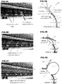
- Figs.2A to 2C and Figs.3A to 3C illustrate how a print-medium accumulates in a print-medium buffer when a print-medium buffering system 10 according to a comparative example is used in the printer of Fig.1 .
- a sheet of print medium P is fed into the print-medium buffer zone by rollers 12.
- a set of print-medium-buffer flags 15 are provided to guide the print-medium sheet P along a guided path G into the print zone.
- the guided path G is along a support surface.
- the print-medium-buffer flags 15 are elongate, generally finger-shaped elements each having one end 15a mounted, independently of the others, to a shaft (not shown) extending in the widthwise direction (i.e. in the direction transverse to the direction of print-medium advance). Each flag 15 is mounted so that it can pivot around the mounting shaft.
- the other end of each print-medium-buffer flag 15 is a free end 15b (labelled in Fig.3C ).
- Fig.2B and Fig.3B illustrate what happens as print medium starts to accumulate in the print-medium buffer zone.
- the sheet of print medium P begins to curve away from the guided path G and, because the flags 15 are free to rotate around the mounting shaft, the flags 15 are raised by the curve in the print medium sheet P.
- Fig.2C and Fig.3C illustrate what happens as the print medium accumulates to a greater degree in the print-medium buffer zone.
- the sheet of print medium P develops a pronounced curve and this lifts the flags 15 still further (indeed in Fig.2C they are raised to the point where they can no longer be seen in the figure because they are masked by a housing portion).
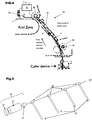
- Fig.4 illustrates an example of a print-medium buffering system 20 according to the present disclosure.
- the print-medium buffering system 20 of this example includes a set of print-medium-buffer flags 25 and a drive mechanism (indicated at 30) for moving the set of print-medium-buffer flags 25.
- each flag is generally finger-like, but this is not essential; other shapes may be used which guide the print medium through the buffer zone and are mounted for rotation in the appropriate direction.
- the flag may be in the form of: a flat plate pivoted along one edge, an L-shaped element with a pivot point at the top of the L, a U-shaped element having pivot points at the top of both arms of the U, and so on.
- the set of print-medium-buffer flags 25 illustrated in the figures has four flags spaced evenly in the widthwise or "cross-process" direction (i.e. in a direction transverse to the direction of advance of the print medium), but this is merely a non-limiting example.
- the set of print-medium buffer flags 25 may comprise one, two, or more than two flags. The spacing between the flags may be varied.
- the flags are made of a plastics material and have a hollow lattice-work structure, to increase stiffness, but once again this is a non-limiting example and, for example, solid flags may be used.
- the flag weight, and the choice of material, depends on the intended application.
- the drive mechanism 30 that moves the set of print-medium-buffer flags 25 is controlled by a control unit 35.
- the control unit 35 controls the times at which the drive mechanism 30 moves the set of print-medium-buffer flags 25.
- the control unit 35 may receive signals (e.g. via a receiver R) from sensors, encoders and other devices that provide information that enables the control unit 35 to determine or estimate the position of the print medium.
- a leading-edge sensor 38 may be provided to detect when the leading edge of a print medium reaches a specified position in the print zone.
- an encoder 40 is provided on a roller 42 that helps to feed the print medium into the print-medium buffer zone, and provides information regarding the state of advancement of a print medium sheet P into the print-medium buffer zone.
- a trailing edge sensor (not shown) may be used to provide the control unit 35 with positional information regarding the print medium.
- the drive mechanism 30 includes a motor 31 (illustrated in Fig.5 ) to drive movement of the set of print-medium-buffer flags 25 between two positions.
- the flags are in the lowered position illustrated in Fig.4 and cooperate with a facing support surface to define a guide channel or guide path along which a sheet of print medium P advances as it passes through the print-medium buffer zone.
- the motive force that causes the print medium sheet P to advance through the print-medium buffer zone derives, initially, from the feed rollers 42.
- the drive mechanism 30 When the leading edge of the print medium sheet P has advanced sufficiently far into the zone that is subsequent to the print-medium buffer zone in the direction of advance of the print medium (i.e. in this example, when the leading edge of the print medium has advanced sufficiently far into the print zone) the drive mechanism 30 is operated to move the set of print-medium buffer flags 25 away from the guide path G to a second position where the flags 25 are out of contact with the print medium sheet P.
- Print medium can accumulate in the print-medium buffer zone while the flags 25 are in the second position and, because the flags 25 are not in contact with the print medium, damage to the medium surface is reduced. Furthermore, because the accumulating print medium is less restricted by the flags 25 when they are in the second position, there is a reduced tendency for print media made of non-rigid materials to deform in an unstable way, and this reduces feeding problems.
- a printer that comprises a print-medium buffering system according to the above example has the advantage of increased versatility because it can handle a high throughput for a wide range of print media, including not only relatively rigid materials but also relatively non-rigid materials, with a reduced risk of jamming.
- the image quality obtained when operating at high throughput is improved, because there is reduced plot damage.
- the drive mechanism 30 moves the set of print-medium-buffer flags 25 to the second position when the leading edge of the print-medium sheet P has advanced "sufficiently far” into the zone subsequent to the print-medium buffer in the transport path of the print medium.
- "sufficiently far” is far enough into the print zone for the leading edge of the print-medium sheet P to be able to experience traction from a feed element in the print zone (so that the print-medium sheet P may reliably advance further into the print zone).
- the print zone includes a set of pinch wheels F which operate to feed a print medium further into the print zone.
- the set of pinch wheels F may include one wheel, two wheels, or more than two wheels.
- the drive motor which moves the print-medium buffer flags 25 is also operative to move the set of print zone pinch wheels F to take them out of contact with a print medium passing through the print zone (e.g. so that a paper jam may be cleared).
- Fig.5 illustrates an example arrangement in which the drive mechanism 30 includes a drive motor and transmission 31 arranged to rotate a shaft 27 to which the print-medium-buffer flags 25 are connected via fixings 28.
- the drive mechanism 30 includes a drive motor and transmission 31 arranged to rotate a shaft 27 to which the print-medium-buffer flags 25 are connected via fixings 28.
- all the print-medium-buffer flags 25 are mounted at the same angle relative to the shaft.
- the shaft 27 may have a flat surface portion enabling the drive motor to apply torque to the shaft.
- a homing mechanism 32 may be provided to enable the first and second positions of the flags 25/shaft 27 to be regulated, for example during initialization of the printer in which the print-medium buffering system is installed.
- An encoder 33 may be provided in association with the drive motor and transmission 31 to enable monitoring of the position of the shaft 27 (and, hence, the monitoring of the angular position of the flags 25).
- the drive mechanism 30 moves the set of print-medium-buffer flags 25 together.
- This grouped movement of the flags 25 may be achieved using different arrangements.
- each of the flags 25 has one end 25a clipped onto a fixing 28 that is mounted on the shaft 27 at a fixed angular position relative to the shaft, and the flag clips are designed not to rotate relative to the fixings 28. Because the print-medium-buffer flags 25 are all mounted to rotate as the shaft 27 rotates they can all be moved together by driving the rotation of the shaft.
- Figs.7A to 7C illustrate an example implementation of a homing mechanism 32 of Fig.5 .
- the homing mechanism includes a drive block 32a that, in this example, is shaped approximately like a quarter circle and is driven by the drive motor to rotate (in the direction indicated by arrow A in Fig.7A ) and thereby rotate the shaft 27.
- the homing mechanism also includes a stopper block 32b having a rotary space in which the drive block 32a can rotate between two extreme positions. The extreme positions of the drive block 32a correspond to the first and second positions of the set of print-medium-buffer flags 25.
- Fig.8A and 8B illustrate an example of timings at which the control unit 35 may control the drive mechanism to move the flags 25 between their first and second positions.
- Fig.8A illustrates an example of a time T1, during passage of a print medium sheet P1 though a print-medium buffer zone, when the drive mechanism 30 is controlled to move the print-medium-buffer flags 25 from their first position to their second position.
- T1 the leading edge of the print medium P1 has reached a position where it can reliably undergo traction from a feed element in the zone subsequent to the print-medium buffer zone (i.e. in this example, traction due to operation of the pinch wheel F in the print zone).
- the feed rollers 42 that feed the print medium into the buffer zone accelerate and print medium accumulates in the buffer zone. In this way, when the feed rollers 42 stop advancing the print medium, to allow the printer's cutting element to cut off a sheet, material from the buffer can still be fed into the print zone, thus enabling continuous feeding of print medium through the print zone.
- Fig.8B illustrates an example of a time T2, as print medium sheet P1 just clears the print-medium buffer zone, when the drive mechanism 30 is controlled to move the print-medium-buffer flags 25 from their second position back to their first position, where they may be operative to guide the next sheet of print medium, P2, into the print zone.
- T2 the trailing edge of the print medium P1 has cleared the print-medium buffer zone and the subsequent sheet P2 has not yet entered the print-medium buffer zone.
- the flags 25 may be in position to ensure correct guiding of the sheet P2 when it enters the print-medium buffer zone (so that its leading edge is successfully fed into the print zone).
- the set of print-medium-buffer flags is driven back from the second position to the first position at the time T2
- the flags may be allowed simply to drop back to the first position at time T2, without explicit driving.
- Print-medium buffering systems enable print-medium sheets to be manually fed to the zone that is subsequent to the buffer zone.
- Systems according to these examples allow the user to control the drive mechanism 30 to move the print-medium-buffer flags 25, as a group, to a position in which they are away from the print medium path. Print media sheets can then be manually fed under the flags 25, as illustrated in Fig.9 .
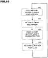
- Fig.10 is a flow diagram illustrating steps in an example of a method of controlling a print-medium buffering system.
- the example method illustrated in Fig.10 includes a state S01 in which a set of print-medium-buffer flags are in a first position and are operative to maintain a print medium in a guided path passing through a print-medium buffer zone.
- a drive mechanism is used (in a step S02) to move the set of print-medium-buffer flags away from the guided path to a second position (state S03).
- the print-medium-buffer flags may be returned to the first position when a return condition is fulfilled (step S04); for example, the print-medium-buffer flags may be returned to the first position when the trailing edge of a print medium sheet has exited the print-medium buffer zone.
- the method may include controlling the drive mechanism to move the set of print-medium buffer flags away from the guided path at a time when the leading edge of the print medium in the print-medium buffer is engaged by the feed element.
- the feed element may comprise a pinch wheel, and the method may comprise using the drive motor to move the pinch wheel and to move the set of print-medium-buffer flags.
- a method of controlling a print-medium buffering system comprises controlling timing of the movement of the set of print-medium-buffer flags by the drive mechanism dependent on a detected or estimated position of the leading edge of the print medium and dependent on a position signal generated by an encoder provided on a second feed element that is at the input zone of the print-medium buffer to feed print media into the print-medium buffer.
- Examples of methods of controlling a print-medium buffering system according to the present disclosure may be applied in cases where the set of print-medium-buffer flags comprises at least one finger element having a mounted end and a free end, and the moving of the set of print-medium-buffer flags may then comprise causing at least one finger element to rotate around its mounted end, to move the free end of the finger element towards and away from the guided path of the print medium.
- Figs.8A and 8B relate to a print-medium buffering system whose buffer zone is located adjacent the input of a zone that contains a pinch wheel, and the position of the print medium relative to the pinch wheel affects the timing of moving the print-medium-buffer flags to their second position
- the feed element it is not essential for the feed element to be a pinch wheel; other feed elements may be used (e.g. conveyor belts, rollers, and so on).
- the examples show feed rollers advancing a print medium into the print-medium buffer zone, but feeding elements different from or additional to feed rollers may be used and, indeed, any convenient feeding arrangement may be used to advance the print medium through the buffer zone.
Landscapes
- Engineering & Computer Science (AREA)
- Mechanical Engineering (AREA)
- Delivering By Means Of Belts And Rollers (AREA)
- Handling Of Sheets (AREA)
- Registering Or Overturning Sheets (AREA)
Claims (11)
- Druckmediumpuffersystem (20), das Folgendes umfasst:
einen Satz von Druckmediumpufferflags (25), die in einer ersten Position betriebsfähig sind, um ein Druckmedium in einem geführten Pfad (G) zu halten, während das Druckmedium eine Druckmediumpufferzone durchläuft; dadurch gekennzeichnet, dass das System ferner Folgendes umfasst:einen Codierer (40), der an einem zweiten Zuführelement (42) bereitgestellt ist, das an der Eingabezone der Druckmediumpufferzone angeordnet ist, um Druckmedien in die Druckmediumpufferzone zuzuführen; undeine Steuereinheit (35), um einen Antriebsmechanismus (30) zu steuern, um den Satz von Druckmediumpufferflags von dem geführten Pfad weg in eine zweite Position zu bewegen, in Abhängigkeit von einem Positionssignal, das durch den Codierer (40) erzeugt wird, wobei die Steuereinheit einen Empfänger (R) umfasst, um das Signal von dem Codierer (40) zu empfangen. - Druckmediumpuffersystem nach Anspruch 1, wobei beim Verlassen der Druckmediumpufferzone ein Druckmedium in eine Zone eintritt, die ein erstes Zuführelement (F) umfasst, und die Steuereinheit (35) synchronisiert ist, um den Antriebsmechanismus (30) zu steuern, um den Satz von Druckmediumpufferflags (25) von dem geführten Pfad (G) zu einem Zeitpunkt wegzubewegen, wenn die Vorderkante eines Druckmediums in der Druckmediumpufferzone durch das erste Zuführelement in Eingriff genommen wird.
- Druckmediumpuffersystem nach Anspruch 2, wobei das erste Zuführelement ein Klemmrad (F) umfasst und der Antriebsmechanismus (30) des Druckmediumpuffersystems einen Antriebsmotor umfasst, der dazu angeordnet ist, das Klemmrad (F) zu bewegen und den Satz von Druckmediumpufferflags (25) zu bewegen.
- Druckmediumpuffersystem nach Anspruch 2, wobei die Steuereinheit einen Sensor (38) umfasst, um die Position der Vorderkante des Druckmediums zu erfassen.
- Druckmediumpuffersystem nach einem der Ansprüche 1 bis 4, wobei der Satz von Druckmediumpufferflags (25) wenigstens ein Fingerelement umfasst, das ein montiertes Ende (25a) und ein freies Ende (25b) aufweist, wobei das Fingerelement montiert ist, um sich unter der Wirkung des Antriebsmechanismus (30) um das montierte Ende zu drehen, um das freie Ende (25b) des Fingerelements zu dem geführten Pfad (G) hin und von diesem weg zu bewegen.
- Drucker (1), der ein Druckmediumpuffersystem nach einem der Ansprüche 1 bis 5 umfasst.
- Verfahren zum Steuern eines Druckmediumpuffersystems, das einen Satz von Druckmediumpufferflags (25) umfasst, die in einer ersten Position betriebsfähig sind, um ein Druckmedium in einem geführten Pfad (G) zu halten, während das Druckmedium eine Druckmediumpufferzone durchläuft, wobei das Verfahren Folgendes umfasst: Bewegen des Satzes von Druckmediumpufferflags (25) von dem geführten Pfad (G) weg in eine zweite Position unter Verwendung eines Antriebsmechanismus (30);
dadurch gekennzeichnet, dass das Verfahren ferner Folgendes umfasst:
Steuern der Zeiteinstellung der Bewegung des Satzes von Druckmediumpufferflags (25) durch den Antriebsmechanismus (30) in Abhängigkeit von einem Positionssignal, das durch einen Codierer (40) erzeugt wird, der an einem zweiten Zuführelement (42) bereitgestellt ist, wobei das zweite Zuführelement (42) an der Eingabezone der Druckmediumpufferzone angeordnet ist, um Druckmedien in die Druckmediumpufferzone zuzuführen. - Verfahren zum Steuern des Druckmediumpuffersystems nach Anspruch 7, wobei beim Verlassen der Druckmediumpufferzone ein Druckmedium in eine Zone eintritt, die ein erstes Zuführelement umfasst, wobei das Verfahren Folgendes umfasst:
Steuern des Antriebsmechanismus (30), um den Satz von Druckmediumpufferflags (25) von dem geführten Pfad (G) zu einem Zeitpunkt wegzubewegen, wenn die Vorderkante des Druckmediums in der Druckmediumpufferzone durch das erste Zuführelement in Eingriff genommen wird. - Verfahren zum Steuern des Druckmediumpuffersystems nach Anspruch 8, wobei das erste Zuführelement ein Klemmrad (F) umfasst und das Verfahren das Verwenden des Antriebsmechanismus (30) zum Bewegen des Klemmrads (F) und zum Bewegen des Satzes von Druckmediumpufferflags (25) umfasst.
- Verfahren zum Steuern des Druckmediumpuffersystems nach Anspruch 8, und das das Steuern der Zeiteinstellung der Bewegung des Satzes von Druckmediumpufferflags (25) durch den Antriebsmechanismus (30) in Abhängigkeit von einer Position der Vorderkante des Druckmediums umfasst.
- Verfahren zum Steuern des Druckmediumpuffersystems nach einem der Ansprüche 7 bis 10, wobei der Satz von Druckmediumpufferflags (25) wenigstens ein Fingerelement umfasst, das ein montiertes Ende (25a) und ein freies Ende (25b) aufweist, und wobei das Bewegen des Satzes von Druckmediumpufferflags (25) das Bewirken umfasst, dass sich wenigstens ein Fingerelement um das montierte Ende (25a) davon dreht, um das freie Ende (25b) des Fingerelement zu dem geführten Pfad (G) des Druckmediums hin und von diesem weg zu bewegen.
Applications Claiming Priority (1)
| Application Number | Priority Date | Filing Date | Title |
|---|---|---|---|
| PCT/EP2014/061192 WO2015180782A1 (en) | 2014-05-28 | 2014-05-28 | Print-medium buffering |
Publications (2)
| Publication Number | Publication Date |
|---|---|
| EP3148905A1 EP3148905A1 (de) | 2017-04-05 |
| EP3148905B1 true EP3148905B1 (de) | 2021-10-27 |
Family
ID=50972645
Family Applications (1)
| Application Number | Title | Priority Date | Filing Date |
|---|---|---|---|
| EP14730783.9A Active EP3148905B1 (de) | 2014-05-28 | 2014-05-28 | Druckmediumpufferung |
Country Status (4)
| Country | Link |
|---|---|
| US (1) | US10301129B2 (de) |
| EP (1) | EP3148905B1 (de) |
| CN (1) | CN106660724B (de) |
| WO (1) | WO2015180782A1 (de) |
Families Citing this family (1)
| Publication number | Priority date | Publication date | Assignee | Title |
|---|---|---|---|---|
| JP7889014B2 (ja) * | 2022-03-29 | 2026-07-14 | 富士フイルムビジネスイノベーション株式会社 | 媒体搬送装置および画像形成装置 |
Family Cites Families (18)
| Publication number | Priority date | Publication date | Assignee | Title |
|---|---|---|---|---|
| US4262895A (en) * | 1979-08-31 | 1981-04-21 | Xerox Corporation | Inverter with variable buckling control |
| JPH07309476A (ja) * | 1994-05-16 | 1995-11-28 | Fuji Xerox Co Ltd | 用紙搬送装置 |
| US5482389A (en) | 1994-11-25 | 1996-01-09 | Westerex International, Division Of Capitol Circuits | Paper feed driven cutter mechanism of an electronic printer |
| US6105957A (en) * | 1998-09-30 | 2000-08-22 | Pitney Bowes Inc. | Buckle accumulator having selectively activateable sheet deflector |
| US6240260B1 (en) | 1999-01-29 | 2001-05-29 | Agfa Corporation | Method and apparatus for buffer transfer of media sheets between components in an imagesetting system |
| JP2002207259A (ja) * | 2001-01-12 | 2002-07-26 | Fuji Photo Film Co Ltd | 画像形成装置 |
| US6826374B2 (en) | 2001-08-31 | 2004-11-30 | Canon Kabushiki Kaisha | Sheet processing apparatus with discharge sheet cover and control based on open/close state of cover |
| JP2003237163A (ja) * | 2002-02-20 | 2003-08-27 | Sharp Corp | 画像形成装置 |
| JP3962605B2 (ja) * | 2002-02-28 | 2007-08-22 | キヤノン株式会社 | シート処理装置及び画像形成装置 |
| US7314075B2 (en) | 2003-04-04 | 2008-01-01 | Nisca Corporation | Adhesive dispensing apparatus and image forming apparatus |
| US6974128B2 (en) * | 2003-06-10 | 2005-12-13 | Xerox Corporation | Sheet registration deskew with plural arcuate independently repositionable baffles |
| JP4689444B2 (ja) * | 2005-11-24 | 2011-05-25 | 株式会社リコー | シート材搬送装置及び画像形成装置 |
| JP4692661B2 (ja) * | 2009-03-19 | 2011-06-01 | ブラザー工業株式会社 | 記録装置 |
| JP5392479B2 (ja) * | 2009-06-01 | 2014-01-22 | セイコーエプソン株式会社 | 用紙反転装置、該用紙反転装置を備えた電子機器 |
| US8585047B2 (en) * | 2010-04-28 | 2013-11-19 | Canon Kabushiki Kaisha | Sheet conveyance apparatus and recording apparatus |
| JP5479439B2 (ja) * | 2011-11-30 | 2014-04-23 | 京セラドキュメントソリューションズ株式会社 | シート搬送装置及びそれを備えた画像形成装置 |
| US8919770B2 (en) | 2012-05-07 | 2014-12-30 | Xerox Corporation | System and method for identification of media sheet size |
| JP2015030572A (ja) * | 2013-08-01 | 2015-02-16 | キヤノン株式会社 | シート搬送装置及び画像形成装置 |
-
2014
- 2014-05-28 EP EP14730783.9A patent/EP3148905B1/de active Active
- 2014-05-28 WO PCT/EP2014/061192 patent/WO2015180782A1/en not_active Ceased
- 2014-05-28 US US15/310,194 patent/US10301129B2/en active Active
- 2014-05-28 CN CN201480079252.6A patent/CN106660724B/zh active Active
Also Published As
| Publication number | Publication date |
|---|---|
| WO2015180782A1 (en) | 2015-12-03 |
| US20170158445A1 (en) | 2017-06-08 |
| CN106660724A (zh) | 2017-05-10 |
| EP3148905A1 (de) | 2017-04-05 |
| US10301129B2 (en) | 2019-05-28 |
| CN106660724B (zh) | 2019-05-31 |
Similar Documents
| Publication | Publication Date | Title |
|---|---|---|
| EP2957513B1 (de) | Etikettenablösungsvorrichtung, fluidausstossvorrichtung und etikettenablösungsverfahren | |
| US10913631B2 (en) | Apparatus and method for cutting or perforating a paper web | |
| JP6506016B2 (ja) | 給紙装置 | |
| US8056893B2 (en) | Media transport system | |
| CN102874619B (zh) | 传送装置、印刷装置以及传送方法 | |
| JP2006036486A (ja) | 搬送装置及び該装置を備えた記録装置 | |
| EP1479628B1 (de) | Schneidvorrichtung für endlosformulare | |
| US9975721B2 (en) | Conveyance device, printer, and conveyance method | |
| EP3277512B1 (de) | Verfahren zur verminderung von medienverzug in medientransportsystemen sowie medientransportsysteme | |
| US7971865B2 (en) | Inserting apparatus for discrete objects into envelopes and related methods | |
| US10301129B2 (en) | Print medium buffering | |
| US9623687B2 (en) | Roll paper conveyance control method, roll paper conveyance device, and printer | |
| EP3152142B1 (de) | Druckvorrichtung, entsprechendes drucksystem, und verfahren zum betrieb einer druckvorrichtung | |
| US9550377B2 (en) | System and method to mitigate media roll curl | |
| JP4822984B2 (ja) | 記録媒体の搬送装置、搬送方法、および記録装置 | |
| US12420569B2 (en) | Printer | |
| US20260027844A1 (en) | Advancing media trailing edges | |
| JP2026006135A (ja) | 搬送装置、記録装置、及び搬送方法 | |
| JPH0569618A (ja) | 手差し給紙装置 | |
| JP5550761B2 (ja) | 記録装置及び記録装置の制御方法 | |
| JP2011093318A (ja) | 搬送装置及び該装置を備えた記録装置 |
Legal Events
| Date | Code | Title | Description |
|---|---|---|---|
| STAA | Information on the status of an ep patent application or granted ep patent |
Free format text: STATUS: THE INTERNATIONAL PUBLICATION HAS BEEN MADE |
|
| PUAI | Public reference made under article 153(3) epc to a published international application that has entered the european phase |
Free format text: ORIGINAL CODE: 0009012 |
|
| STAA | Information on the status of an ep patent application or granted ep patent |
Free format text: STATUS: REQUEST FOR EXAMINATION WAS MADE |
|
| 17P | Request for examination filed |
Effective date: 20161110 |
|
| AK | Designated contracting states |
Kind code of ref document: A1 Designated state(s): AL AT BE BG CH CY CZ DE DK EE ES FI FR GB GR HR HU IE IS IT LI LT LU LV MC MK MT NL NO PL PT RO RS SE SI SK SM TR |
|
| AX | Request for extension of the european patent |
Extension state: BA ME |
|
| DAX | Request for extension of the european patent (deleted) | ||
| RAP1 | Party data changed (applicant data changed or rights of an application transferred) |
Owner name: HEWLETT-PACKARD DEVELOPMENT COMPANY, L.P. |
|
| GRAP | Despatch of communication of intention to grant a patent |
Free format text: ORIGINAL CODE: EPIDOSNIGR1 |
|
| STAA | Information on the status of an ep patent application or granted ep patent |
Free format text: STATUS: GRANT OF PATENT IS INTENDED |
|
| INTG | Intention to grant announced |
Effective date: 20210722 |
|
| GRAS | Grant fee paid |
Free format text: ORIGINAL CODE: EPIDOSNIGR3 |
|
| GRAA | (expected) grant |
Free format text: ORIGINAL CODE: 0009210 |
|
| STAA | Information on the status of an ep patent application or granted ep patent |
Free format text: STATUS: THE PATENT HAS BEEN GRANTED |
|
| AK | Designated contracting states |
Kind code of ref document: B1 Designated state(s): AL AT BE BG CH CY CZ DE DK EE ES FI FR GB GR HR HU IE IS IT LI LT LU LV MC MK MT NL NO PL PT RO RS SE SI SK SM TR |
|
| REG | Reference to a national code |
Ref country code: GB Ref legal event code: FG4D |
|
| REG | Reference to a national code |
Ref country code: CH Ref legal event code: EP |
|
| REG | Reference to a national code |
Ref country code: AT Ref legal event code: REF Ref document number: 1441612 Country of ref document: AT Kind code of ref document: T Effective date: 20211115 |
|
| REG | Reference to a national code |
Ref country code: DE Ref legal event code: R096 Ref document number: 602014080878 Country of ref document: DE |
|
| REG | Reference to a national code |
Ref country code: IE Ref legal event code: FG4D |
|
| REG | Reference to a national code |
Ref country code: LT Ref legal event code: MG9D |
|
| REG | Reference to a national code |
Ref country code: NL Ref legal event code: MP Effective date: 20211027 |
|
| REG | Reference to a national code |
Ref country code: AT Ref legal event code: MK05 Ref document number: 1441612 Country of ref document: AT Kind code of ref document: T Effective date: 20211027 |
|
| PG25 | Lapsed in a contracting state [announced via postgrant information from national office to epo] |
Ref country code: RS Free format text: LAPSE BECAUSE OF FAILURE TO SUBMIT A TRANSLATION OF THE DESCRIPTION OR TO PAY THE FEE WITHIN THE PRESCRIBED TIME-LIMIT Effective date: 20211027 Ref country code: LT Free format text: LAPSE BECAUSE OF FAILURE TO SUBMIT A TRANSLATION OF THE DESCRIPTION OR TO PAY THE FEE WITHIN THE PRESCRIBED TIME-LIMIT Effective date: 20211027 Ref country code: FI Free format text: LAPSE BECAUSE OF FAILURE TO SUBMIT A TRANSLATION OF THE DESCRIPTION OR TO PAY THE FEE WITHIN THE PRESCRIBED TIME-LIMIT Effective date: 20211027 Ref country code: BG Free format text: LAPSE BECAUSE OF FAILURE TO SUBMIT A TRANSLATION OF THE DESCRIPTION OR TO PAY THE FEE WITHIN THE PRESCRIBED TIME-LIMIT Effective date: 20220127 Ref country code: AT Free format text: LAPSE BECAUSE OF FAILURE TO SUBMIT A TRANSLATION OF THE DESCRIPTION OR TO PAY THE FEE WITHIN THE PRESCRIBED TIME-LIMIT Effective date: 20211027 |
|
| PG25 | Lapsed in a contracting state [announced via postgrant information from national office to epo] |
Ref country code: IS Free format text: LAPSE BECAUSE OF FAILURE TO SUBMIT A TRANSLATION OF THE DESCRIPTION OR TO PAY THE FEE WITHIN THE PRESCRIBED TIME-LIMIT Effective date: 20220227 Ref country code: SE Free format text: LAPSE BECAUSE OF FAILURE TO SUBMIT A TRANSLATION OF THE DESCRIPTION OR TO PAY THE FEE WITHIN THE PRESCRIBED TIME-LIMIT Effective date: 20211027 Ref country code: PT Free format text: LAPSE BECAUSE OF FAILURE TO SUBMIT A TRANSLATION OF THE DESCRIPTION OR TO PAY THE FEE WITHIN THE PRESCRIBED TIME-LIMIT Effective date: 20220228 Ref country code: PL Free format text: LAPSE BECAUSE OF FAILURE TO SUBMIT A TRANSLATION OF THE DESCRIPTION OR TO PAY THE FEE WITHIN THE PRESCRIBED TIME-LIMIT Effective date: 20211027 Ref country code: NO Free format text: LAPSE BECAUSE OF FAILURE TO SUBMIT A TRANSLATION OF THE DESCRIPTION OR TO PAY THE FEE WITHIN THE PRESCRIBED TIME-LIMIT Effective date: 20220127 Ref country code: NL Free format text: LAPSE BECAUSE OF FAILURE TO SUBMIT A TRANSLATION OF THE DESCRIPTION OR TO PAY THE FEE WITHIN THE PRESCRIBED TIME-LIMIT Effective date: 20211027 Ref country code: LV Free format text: LAPSE BECAUSE OF FAILURE TO SUBMIT A TRANSLATION OF THE DESCRIPTION OR TO PAY THE FEE WITHIN THE PRESCRIBED TIME-LIMIT Effective date: 20211027 Ref country code: HR Free format text: LAPSE BECAUSE OF FAILURE TO SUBMIT A TRANSLATION OF THE DESCRIPTION OR TO PAY THE FEE WITHIN THE PRESCRIBED TIME-LIMIT Effective date: 20211027 Ref country code: GR Free format text: LAPSE BECAUSE OF FAILURE TO SUBMIT A TRANSLATION OF THE DESCRIPTION OR TO PAY THE FEE WITHIN THE PRESCRIBED TIME-LIMIT Effective date: 20220128 Ref country code: ES Free format text: LAPSE BECAUSE OF FAILURE TO SUBMIT A TRANSLATION OF THE DESCRIPTION OR TO PAY THE FEE WITHIN THE PRESCRIBED TIME-LIMIT Effective date: 20211027 |
|
| REG | Reference to a national code |
Ref country code: DE Ref legal event code: R097 Ref document number: 602014080878 Country of ref document: DE |
|
| PG25 | Lapsed in a contracting state [announced via postgrant information from national office to epo] |
Ref country code: SM Free format text: LAPSE BECAUSE OF FAILURE TO SUBMIT A TRANSLATION OF THE DESCRIPTION OR TO PAY THE FEE WITHIN THE PRESCRIBED TIME-LIMIT Effective date: 20211027 Ref country code: SK Free format text: LAPSE BECAUSE OF FAILURE TO SUBMIT A TRANSLATION OF THE DESCRIPTION OR TO PAY THE FEE WITHIN THE PRESCRIBED TIME-LIMIT Effective date: 20211027 Ref country code: RO Free format text: LAPSE BECAUSE OF FAILURE TO SUBMIT A TRANSLATION OF THE DESCRIPTION OR TO PAY THE FEE WITHIN THE PRESCRIBED TIME-LIMIT Effective date: 20211027 Ref country code: EE Free format text: LAPSE BECAUSE OF FAILURE TO SUBMIT A TRANSLATION OF THE DESCRIPTION OR TO PAY THE FEE WITHIN THE PRESCRIBED TIME-LIMIT Effective date: 20211027 Ref country code: DK Free format text: LAPSE BECAUSE OF FAILURE TO SUBMIT A TRANSLATION OF THE DESCRIPTION OR TO PAY THE FEE WITHIN THE PRESCRIBED TIME-LIMIT Effective date: 20211027 Ref country code: CZ Free format text: LAPSE BECAUSE OF FAILURE TO SUBMIT A TRANSLATION OF THE DESCRIPTION OR TO PAY THE FEE WITHIN THE PRESCRIBED TIME-LIMIT Effective date: 20211027 |
|
| PLBE | No opposition filed within time limit |
Free format text: ORIGINAL CODE: 0009261 |
|
| STAA | Information on the status of an ep patent application or granted ep patent |
Free format text: STATUS: NO OPPOSITION FILED WITHIN TIME LIMIT |
|
| 26N | No opposition filed |
Effective date: 20220728 |
|
| PG25 | Lapsed in a contracting state [announced via postgrant information from national office to epo] |
Ref country code: AL Free format text: LAPSE BECAUSE OF FAILURE TO SUBMIT A TRANSLATION OF THE DESCRIPTION OR TO PAY THE FEE WITHIN THE PRESCRIBED TIME-LIMIT Effective date: 20211027 |
|
| PG25 | Lapsed in a contracting state [announced via postgrant information from national office to epo] |
Ref country code: SI Free format text: LAPSE BECAUSE OF FAILURE TO SUBMIT A TRANSLATION OF THE DESCRIPTION OR TO PAY THE FEE WITHIN THE PRESCRIBED TIME-LIMIT Effective date: 20211027 |
|
| REG | Reference to a national code |
Ref country code: CH Ref legal event code: PL |
|
| REG | Reference to a national code |
Ref country code: BE Ref legal event code: MM Effective date: 20220531 |
|
| PG25 | Lapsed in a contracting state [announced via postgrant information from national office to epo] |
Ref country code: MC Free format text: LAPSE BECAUSE OF FAILURE TO SUBMIT A TRANSLATION OF THE DESCRIPTION OR TO PAY THE FEE WITHIN THE PRESCRIBED TIME-LIMIT Effective date: 20211027 Ref country code: LU Free format text: LAPSE BECAUSE OF NON-PAYMENT OF DUE FEES Effective date: 20220528 Ref country code: LI Free format text: LAPSE BECAUSE OF NON-PAYMENT OF DUE FEES Effective date: 20220531 Ref country code: CH Free format text: LAPSE BECAUSE OF NON-PAYMENT OF DUE FEES Effective date: 20220531 |
|
| PG25 | Lapsed in a contracting state [announced via postgrant information from national office to epo] |
Ref country code: IE Free format text: LAPSE BECAUSE OF NON-PAYMENT OF DUE FEES Effective date: 20220528 |
|
| PG25 | Lapsed in a contracting state [announced via postgrant information from national office to epo] |
Ref country code: IT Free format text: LAPSE BECAUSE OF FAILURE TO SUBMIT A TRANSLATION OF THE DESCRIPTION OR TO PAY THE FEE WITHIN THE PRESCRIBED TIME-LIMIT Effective date: 20211027 Ref country code: BE Free format text: LAPSE BECAUSE OF NON-PAYMENT OF DUE FEES Effective date: 20220531 |
|
| PG25 | Lapsed in a contracting state [announced via postgrant information from national office to epo] |
Ref country code: HU Free format text: LAPSE BECAUSE OF FAILURE TO SUBMIT A TRANSLATION OF THE DESCRIPTION OR TO PAY THE FEE WITHIN THE PRESCRIBED TIME-LIMIT; INVALID AB INITIO Effective date: 20140528 |
|
| PG25 | Lapsed in a contracting state [announced via postgrant information from national office to epo] |
Ref country code: MK Free format text: LAPSE BECAUSE OF FAILURE TO SUBMIT A TRANSLATION OF THE DESCRIPTION OR TO PAY THE FEE WITHIN THE PRESCRIBED TIME-LIMIT Effective date: 20211027 Ref country code: CY Free format text: LAPSE BECAUSE OF FAILURE TO SUBMIT A TRANSLATION OF THE DESCRIPTION OR TO PAY THE FEE WITHIN THE PRESCRIBED TIME-LIMIT Effective date: 20211027 |
|
| PG25 | Lapsed in a contracting state [announced via postgrant information from national office to epo] |
Ref country code: MT Free format text: LAPSE BECAUSE OF FAILURE TO SUBMIT A TRANSLATION OF THE DESCRIPTION OR TO PAY THE FEE WITHIN THE PRESCRIBED TIME-LIMIT Effective date: 20211027 |
|
| REG | Reference to a national code |
Ref country code: DE Ref legal event code: R082 Ref document number: 602014080878 Country of ref document: DE Representative=s name: NOVAGRAAF BREVETS, FR |
|
| PG25 | Lapsed in a contracting state [announced via postgrant information from national office to epo] |
Ref country code: TR Free format text: LAPSE BECAUSE OF FAILURE TO SUBMIT A TRANSLATION OF THE DESCRIPTION OR TO PAY THE FEE WITHIN THE PRESCRIBED TIME-LIMIT Effective date: 20211027 |
|
| PGFP | Annual fee paid to national office [announced via postgrant information from national office to epo] |
Ref country code: GB Payment date: 20260421 Year of fee payment: 13 |
|
| PGFP | Annual fee paid to national office [announced via postgrant information from national office to epo] |
Ref country code: DE Payment date: 20250724 Year of fee payment: 13 |
|
| PGFP | Annual fee paid to national office [announced via postgrant information from national office to epo] |
Ref country code: FR Payment date: 20260422 Year of fee payment: 13 |