EP3149259B1 - Scaffolding coupler and scaffolding system - Google Patents
Scaffolding coupler and scaffolding system Download PDFInfo
- Publication number
- EP3149259B1 EP3149259B1 EP15732968.1A EP15732968A EP3149259B1 EP 3149259 B1 EP3149259 B1 EP 3149259B1 EP 15732968 A EP15732968 A EP 15732968A EP 3149259 B1 EP3149259 B1 EP 3149259B1
- Authority
- EP
- European Patent Office
- Prior art keywords
- scaffolding
- standard
- ledger
- projection
- pin
- Prior art date
- Legal status (The legal status is an assumption and is not a legal conclusion. Google has not performed a legal analysis and makes no representation as to the accuracy of the status listed.)
- Active
Links
Images





Classifications
-
- E—FIXED CONSTRUCTIONS
- E04—BUILDING
- E04G—SCAFFOLDING; FORMS; SHUTTERING; BUILDING IMPLEMENTS OR AIDS, OR THEIR USE; HANDLING BUILDING MATERIALS ON THE SITE; REPAIRING, BREAKING-UP OR OTHER WORK ON EXISTING BUILDINGS
- E04G7/00—Connections between parts of the scaffold
- E04G7/30—Scaffolding bars or members with non-detachably fixed coupling elements
- E04G7/302—Scaffolding bars or members with non-detachably fixed coupling elements for connecting crossing or intersecting bars or members
- E04G7/306—Scaffolding bars or members with non-detachably fixed coupling elements for connecting crossing or intersecting bars or members the added coupling elements are fixed at several bars or members to connect
- E04G7/307—Scaffolding bars or members with non-detachably fixed coupling elements for connecting crossing or intersecting bars or members the added coupling elements are fixed at several bars or members to connect with tying means for connecting the bars or members
-
- E—FIXED CONSTRUCTIONS
- E04—BUILDING
- E04G—SCAFFOLDING; FORMS; SHUTTERING; BUILDING IMPLEMENTS OR AIDS, OR THEIR USE; HANDLING BUILDING MATERIALS ON THE SITE; REPAIRING, BREAKING-UP OR OTHER WORK ON EXISTING BUILDINGS
- E04G1/00—Scaffolds primarily resting on the ground
- E04G1/02—Scaffolds primarily resting on the ground composed essentially of members elongated in one dimension [1D] only, e.g. poles, lattice masts, with or without end portions of special form, connected together by any means
- E04G1/04—Scaffolds primarily resting on the ground composed essentially of members elongated in one dimension [1D] only, e.g. poles, lattice masts, with or without end portions of special form, connected together by any means the members being exclusively poles, rods, beams, or other members of similar form and simple cross-section
- E04G1/06—Scaffolds primarily resting on the ground composed essentially of members elongated in one dimension [1D] only, e.g. poles, lattice masts, with or without end portions of special form, connected together by any means the members being exclusively poles, rods, beams, or other members of similar form and simple cross-section comprising members with rod-like or tubular portions fitting together end to end, with or without separate connecting pieces
-
- E—FIXED CONSTRUCTIONS
- E04—BUILDING
- E04G—SCAFFOLDING; FORMS; SHUTTERING; BUILDING IMPLEMENTS OR AIDS, OR THEIR USE; HANDLING BUILDING MATERIALS ON THE SITE; REPAIRING, BREAKING-UP OR OTHER WORK ON EXISTING BUILDINGS
- E04G1/00—Scaffolds primarily resting on the ground
- E04G1/02—Scaffolds primarily resting on the ground composed essentially of members elongated in one dimension [1D] only, e.g. poles, lattice masts, with or without end portions of special form, connected together by any means
- E04G1/12—Scaffolds primarily resting on the ground composed essentially of members elongated in one dimension [1D] only, e.g. poles, lattice masts, with or without end portions of special form, connected together by any means comprising members of special, e.g. composite, cross-section or with lugs or the like or lateral apertures for supporting or attaching other members
-
- E—FIXED CONSTRUCTIONS
- E04—BUILDING
- E04G—SCAFFOLDING; FORMS; SHUTTERING; BUILDING IMPLEMENTS OR AIDS, OR THEIR USE; HANDLING BUILDING MATERIALS ON THE SITE; REPAIRING, BREAKING-UP OR OTHER WORK ON EXISTING BUILDINGS
- E04G7/00—Connections between parts of the scaffold
- E04G7/30—Scaffolding bars or members with non-detachably fixed coupling elements
- E04G7/301—Scaffolding bars or members with non-detachably fixed coupling elements for connecting bars or members which are parallel or in end-to-end relation
-
- E—FIXED CONSTRUCTIONS
- E04—BUILDING
- E04G—SCAFFOLDING; FORMS; SHUTTERING; BUILDING IMPLEMENTS OR AIDS, OR THEIR USE; HANDLING BUILDING MATERIALS ON THE SITE; REPAIRING, BREAKING-UP OR OTHER WORK ON EXISTING BUILDINGS
- E04G7/00—Connections between parts of the scaffold
- E04G7/30—Scaffolding bars or members with non-detachably fixed coupling elements
- E04G7/32—Scaffolding bars or members with non-detachably fixed coupling elements with coupling elements using wedges
Definitions
- the invention relates to a scaffolding coupler which is fixedly connected with the ends of a ledger and serves for coupling the ledger to a standard or to another ledger.
- the invention further relates to a scaffolding system comprising standards and ledgers.
- WO2012/128630 relates to a scaffolding system of the type where the standards comprise supporting projections which are formed through plastic deformation of the pipe wall of the standard.
- the ledgers comprise couplers with the aid of which a ledger can be attached to a standard, whereby the coupling rests on a supporting projection of the standard in a ledger connecting zone of this standard.
- the projections are provided through plastic deformation of the pipe wall, they do not lead to weight increase of the standard, as is the case with scaffolding systems where the standards comprise annular flanges.
- the supporting projections and hence the ledger can be disposed at a smaller distance from each other than the mutual distance customary with annular flanges.
- each supporting projection can support two scaffolding couplers, so that two aligned ledgers can be connected to the standard.
- a scaffolding system comprises at least two standards, longitudinal ledgers and transverse ledgers.
- a drawback of the system described in WO2012/128630 resides in the couplers of transverse ledgers resting on the couplers of the longitudinal ledgers which in turn rest on a supporting projection, or the other way around.
- longitudinal ledgers should be used too, because otherwise there is nowhere to rest the transverse ledgers that have to be connected to the standards. In some cases, this leads to placement of a larger number of longitudinal ledgers than required from a viewpoint of strength and rigidity of the entire scaffolding.
- the additional longitudinal ledgers are only necessary for supporting the scaffolding couplers of the transverse ledgers. The consequences are that it takes longer to erect the scaffolding and that a larger amount of longitudinal ledgers is required for erecting the scaffolding. Both consequences lead to high costs of the scaffolding, which is undesired.
- the scaffolding coupler known from WO2012/128630 which discloses the features of the preamble of claim 1, comprises four parts, a first casting comprising a foot and a hook integrally connected therewith, a securing element, a hinge pin with the aid of which the securing element is pivotally connected to the hook, and a wedge which is slideably received in a wedge opening in the hook.
- This scaffolding coupler requires several mounting operations in order to be assembled. Due to the four parts and the mounting operations, the known scaffolding coupler is relatively expensive.
- the invention contemplates a scaffolding coupler which, while maintaining the above described advantages of the known scaffolding coupler, remedies the above described disadvantages of the known scaffolding coupler at least in part. It should be noted that the above described disadvantages and problems have been recognized by the inventor and therefore do not form part of the state of the art. More particularly, the object of the invention is a scaffolding coupler which consists of fewer parts and hence can be manufactured at a lower cost price.
- the invention provides a scaffolding coupler intended for fixed attachment to the ends of a ledger of a scaffolding system, wherein the scaffolding system comprises standards and ledgers, wherein each standard comprises:
- the scaffolding coupler therefore consists of only two parts, i.e., a first part comprising the foot and the hook and a second part which is formed by the bent pin. In one embodiment, both parts can also be configured as a casting or forging. Such a scaffolding coupler consisting of only two parts can be manufactured relatively inexpensively.
- the bent pin provides for clamping of the scaffolding coupler on a scaffolding pipe to which the scaffolding coupler is connected. The gradual increase in thickness of the pin is such that this is self-locking, which means that, once it has been struck into place, the bent pin cannot become detached by vibrations. Only by actively striking the bent pin loose can the bent pin be brought into the releasing condition, so that the scaffolding coupler can be taken from the pipe again. Further embodiments of the scaffolding coupler are described in the subclaims and will be further elucidated in the following on the basis of an example with reference to the figures.
- the invention also provides a scaffolding system comprising standards and ledgers, wherein at least one of the standards comprises:
- Such a scaffolding system offers the advantage that the scaffolding couplers of the transverse ledgers do not rest on the scaffolding couplers of the longitudinal ledgers or the other way around. Instead, the scaffolding couplers of the longitudinal ledgers have, in each ledger connecting zone, their own associated supporting projection on the standard and the scaffolding couplers of the transverse ledgers have, in each ledger connecting zone, their own associated supporting projection on the standard. Consequently, there is no need to place longitudinal ledgers which are not necessary from a viewpoint of strength and rigidity of the scaffolding, but which would only be placed to provide a supporting surface for the scaffolding couplers of the transverse ledgers. Erecting scaffolding can thus be realized faster and with fewer ledgers than with the scaffolding known from WO2012/128630 .
- Figs. 1-7 show an example of a scaffolding coupler in which various embodiments as described in the subclaims are embodied. It is noted that the embodiments can also be utilized independently of each other and that the invention is not limited to the example shown in the figures.
- various embodiments will be described, while, with the aid of reference numerals, reference is made to the figures. The reference numerals are herein used for clarification but have no limitative effect. An embodiment can also be configured in another manner than represented in the example shown in the figures.
- the invention provides a scaffolding coupler 10 intended for fixed connection to the ends of a ledger 100 of a scaffolding system, for instance by means of a welded joint.
- the scaffolding system comprises in any case ledgers 100 and standards 110.
- An example of an embodiment of a standard 110 is shown in Fig. 8 .
- Each standard 110 comprises an elongate pipe wall 112 with a longitudinal central axis Ls.
- the cross section of the pipe wall 112 of the standards 110 is usually circular. This also holds true for the cross section of the ledgers 100.
- Each standard 110 further comprises a number of supporting projections 114 which extend in tangential direction of the pipe wall 112 and which are formed through plastic deformation of the pipe wall 112.
- Each supporting projection 114 comprises, viewed tangentially to the pipe wall 112, with the standard 110 in vertical orientation, a number of alternately arranged raised parts 114a and lowered parts 114b.
- the scaffolding coupler 10 which is intended for such a scaffolding system comprises a foot 12 having a first side 14 that is configured for fixed connection to a ledger pipe end 102 of a first ledger 100.
- a hook 18 is integrally connected with the foot 12.
- the hook 18 has a radial inside contour 20 which is substantially circular segmental.
- the scaffolding coupler 10 further has at least one supporting surface 22, 22' which is formed by the foot 12 and the hook 18 and which, with the scaffolding coupler 10 connected to a standard 110, rests on a supporting surface 114 of the respective standard 110 (see Fig. 16 ).
- the supporting surface 22, 22' is provided with at least one recess 24, 24' which is configured for receiving a raised part 114a of this supporting projection 114 for tangential orientation of the scaffolding coupler 10 relative to the standard 110.
- the scaffolding coupler comprises two such supporting surfaces 22, 22', a first supporting surface 22 and an opposite, second supporting surface 22'.
- the second supporting surface 22' faces up.
- the first supporting surface 22 faces up.
- the provision of two such supporting surfaces 22 therefore enables the ledger 100 to be connected to a standard 110 in two manners.
- the scaffolding coupler 10 further comprises a pin 26 which is slideably connected to the hook 18.
- the pin 26 is a bent pin, comprising a substantially circular segmental inside contour 28 which is located on a radial inside of the bent pin 26, and which, in use, abuts directly against a pipe wall 112 of a standard 110 or a ledger to be coupled to the first ledger 100.
- the bent pin 26 has a substantially circular segmental outside contour 30 which is on a radial outside of the bent pin 26 and which abuts against the substantially circular segmental inside contour 20 of the hook 18.
- the inside contour 28 of the bent pin 26 together with the foot supporting surface 16 define a pipe receiving space 32 having a longitudinal central axis Lc which, in coupled condition with a standard 110 or ledger 100, substantially coincides with a longitudinal central axis Ls of this standard or ledger.
- the inside contour 28 and the outside contour 30 of the pin 26 are oriented relative to each other such that, viewed from a first free end 34 to a second free end 36 of the pin 26, a radial thickness of the bent pin 26 gradually increases.
- the bent pin 26 is received in the hook 18 so as to be tangentially slideable.
- the gradual increase of the radial thickness is preferably so gradual that the bent pin is self-locking.
- the bent pin 26 can be fork-shaped at a first free end 34 and can comprise two fork teeth 38, 40 between which extends a fork recess 42 with a particular height H1.
- the inside contour 20 of the hook 18 can comprise a back 44 extending in tangential direction and having a height H2 which is such that the back 44 is received substantially fittingly in the fork recess 42 so that, viewed in the direction of the longitudinal central axis Lc of the pipe receiving space 32, the bent pin 26 is fixed relative to the hook 18.
- a maximum total height of the pin 26 can be provided.
- the total height of the hook 18 must be as limited as possible, to allow the height of the ledger connecting zone to be as limited as possible.
- the thickness of a scaffolding floor assembly formed by longitudinal ledgers, transverse ledgers and floor parts, can be as minimal as possible, so that in the scaffolding, an optimal passage between the successive floors of the scaffolding is obtained. If the pin is not of forked design, it needs to be enclosed both at the top and at the bottom by a wall part of the hook in order to provide vertical fixation of the pin relative to the hook.
- the bent pin 26 can comprise, at the second end 36 thereof on the radial outside, an integrally connected engaging projection 46 which extends radially outwards from the radial outside contour 30, while the hook 18 is provided with a recess 48 extending in tangential direction, through which recess reaches the engaging projection 46 of the bent pin 26.
- the engaging projection 46 has the advantage that both for securing and for loosening the bent pin 26 with a hammer, the same engaging projection 46 can be struck with a hammer.
- the scaffolder will therefore be sure that he can release the pin 26 of the scaffolding coupler because, as the engaging projection 46 thereof was accessible to a hammer when the scaffolding coupler 10 was being mounted, this engaging projection 46 will also be accessible to a hammer upon demounting of the scaffolding coupler 10.
- the standards 110 can also comprise retaining projections 116 provided in the pipe wall 112 through plastic deformation.
- the retaining projection 116 can be associated, while the retaining projection 116 is arranged, with the standard 110 in vertical orientation, above the supporting projection 114 associated therewith.
- an embodiment of the scaffolding coupler 10 can comprise a bent pin 26 having a top surface 50 and a bottom surface 52.
- the top surface 50 engages an underside of the retaining projection 116 associated with the supporting projection 114 on which rests the scaffolding coupler 10 (see Fig. 9 ), so that the scaffolding coupler is confined between the supporting projection 114 and the associated retaining projection 116. What is prevented in this manner is that the ledger 10 with the scaffolding coupler 10 connected thereto tilts away from the standard, even when the bent pin 26 is not yet secured.
- a scaffolder can first place a ledger 10, then let go of it, for instance to grab a hammer, and only then strike in place the bent pin of the two scaffolding couplers 10 of the respective ledger 100.
- the ledger 100 remains in place.
- the top surface 50 and the bottom surface 52 of the bent pin 26 can each, at an equal angle to a plane perpendicular to the central axis Lc, extend away from each other in wedge-shape configuration for forming an ascending surface.
- the scaffolding coupler 10 is clamped in vertical direction between the supporting projection 114 and the retaining projection 116.
- the bottom surface 52 of the pin is also designed as ascending surface, so that the same effect is also obtained when the scaffolding coupler is placed the other way around on a standard 110. This provides for an even more rigid connection between the respective scaffolding coupler 10 and the standard 110 as well as for a more accurate positioning of the scaffolding coupler 10 on the standard 110.
- the hook 18 can comprise a stop projection 54 which is integrally connected with the hook 18.
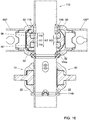
- the stop projection 54 is positioned on the hook 18 such that, when connecting to a standard 110 a first and a second ledger 100, 100' that are each in line with each other and each rest on the same supporting projection 114 of the standard 110, the foot 12 of the scaffolding coupler 10 of the first ledger 100 engages the stop projection 54' of the scaffolding coupler 10' of the second ledger 100' and vice versa (see Fig. 15 ).
- the orientation of the first and the second ledger 100, 100' relative to each other is not exclusively defined by tangential orientation of the first ledger 100 and the second ledger 100' relative to the standard 110 through cooperation of the profiled supporting projection 114 with recesses 24 in the supporting surfaces 22 of the two scaffolding couplers 10, 10', but this mutual orientation is also defined by the mutual engagement of the scaffolding couplers 10, 10' of each other via the stop projections 54, 54'.
- the aligned ledgers 100, 100' and 100", 100'" will have hardly any clearance relative to each other, so that a scaffolding as a whole forms a more rigid and stable construction.
- two aligned ledgers 100, 100' in effect form one rigid whole, acting as a single, continuous pipe. This leads to a more rigid construction of the scaffolding as a whole.
- a distance between the top surface 50 and the bottom surface 52 of the pin 26, i.e., the height H3 (see Fig. 16 ) of the pin 26, can be at least 14 mm.
- a distance between the mutually facing surfaces of the fork teeth 38, 40, i.e., the height of the fork recess H1 can be at least 4 mm and at most 8 mm.
- the fork teeth 38, 40 viewed in the direction of the central axis Lc of the pipe receiving space, can have a height H4 which is at least 5 mm.
- the scaffolding coupler 10 may be provided with a recess 56 which is configured for receiving a free end of the hook 18' and the first end 34' of the pin 26' of a second scaffolding coupler 10' of the same type when this second scaffolding coupler 10' rests on the same supporting projection 114 of a standard 110 as the respective scaffolding coupler 10.
- ledgers 100, 100' can be connected to a standard 110 in line with each other at the same height.
- the invention also relates to a scaffolding system.
- a scaffolding system comprises standards 110 and ledgers 100.
- At least one of the standards 110 of the scaffolding system comprises an elongate pipe wall 112 having a central longitudinal axis Ls and a number of supporting projections 114 extending substantially in tangential direction of the pipe wall 112, which have been formed by plastic deformation of the pipe wall 112.
- Each supporting projection 114 comprises, viewed in a tangential direction of the pipe wall 112, when the standard 110 is vertically oriented, a number of alternately arranged raised parts 114a and lowered parts 114b.
- At least one of the ledgers 100 of the scaffolding system comprises at least at one of the ends 102 a scaffolding coupler 10 according to the invention.
- each standard 110 in addition to the above-mentioned supporting projections 114, can further comprise retaining projections 116 provided in the standard pipe wall 112 through plastic deformation.
- each supporting projection 114 at least one retaining projection 116 is associated.
- the retaining projection 116 is provided above the supporting projection 114 associated therewith.
- a ledger 100 can be placed on a standard 110 and continues to sit in this position without the pins 26 of the two scaffolding couplers 10 of the ledger 100 being secured.
- the ledger's falling out is prevented by the hooks 18 hooking under the retaining projections 116 of the two standards 110. This provides a great advantage in erecting scaffolding.
- the scaffolding couplers of the ledgers can each comprise a stop projection 54 which is integrally connected with the hook 18 on a radially outwardly facing part thereof, while the stop projection 54 is positioned on the hook 18 such that, when connecting a first and a second ledger 100, 100' to a standard 110, with the first and the second ledger being in line with each other and each resting on the same supporting projection 114 of the standard 110, the foot 12 of the scaffolding coupler 10 of the first ledger 100 engages the stop projection 54' of the scaffolding coupler 10' of the second ledger 100' and vice versa.
- That engagement is such that the orientation of the first and the second ledger 100, 100' relative to each other is not exclusively defined by tangential orientation of the first ledger 100 and the second ledger 100' relative to the standard 110 through cooperation of the profiled supporting projection 114 with recesses 24 in the supporting surfaces 22 of the two scaffolding couplers 10, 10', but also by the mutual engagement of the scaffolding couplers 10, 10' via the stop projections 54, 54'. Moreover, the positioning of the stop projections 54, 54' is such that the first ledger 100 and the second ledger 100' substantially behave as a single continuous pipe.
- each standard 110 can comprise, at regular distances, a ledger connecting zone 118, while in each ledger connecting zone 118 a first supporting projection 114 of the type mentioned is provided for connecting to the standard 110 of ledgers 100, 100' which extend in a first direction and in each ledger connecting zone 118, at a small distance above this first supporting projection 114, the standard comprises a second supporting projection 114' of the type mentioned for connecting to the standard of ledgers 100", 100'" which extend in a second direction.
- the slight distance between the two supporting projections 114, 114' in a ledger connecting zone 118 of the standard 110 is as small as possible, but sufficient to place on the lower supporting projection 114 at least one scaffolding coupler 10 without this interfering, upon placement, with the upper supporting projection 114'.
- a scaffolding floor assembly which comprises longitudinal ledgers, transverse ledgers and floor parts, is as small as possible.
- the passage between two floors of a scaffolding is obstructed as little as possible.
- the regular distance Dp between successive ledger connecting zones 118 may be at least 25 cm and at most 70 cm. Owing to this relatively small distance, in erecting the scaffolding, a large flexibility is obtained with respect to the positioning of the ledgers 100 on the standards 110. This allows scaffoldings to be erected for many applications.
Landscapes
- Engineering & Computer Science (AREA)
- Architecture (AREA)
- Mechanical Engineering (AREA)
- Civil Engineering (AREA)
- Structural Engineering (AREA)
- Chemical & Material Sciences (AREA)
- Composite Materials (AREA)
- Mutual Connection Of Rods And Tubes (AREA)
- Bridges Or Land Bridges (AREA)
Description
- The invention relates to a scaffolding coupler which is fixedly connected with the ends of a ledger and serves for coupling the ledger to a standard or to another ledger. The invention further relates to a scaffolding system comprising standards and ledgers.
-
WO2012/128630 relates to a scaffolding system of the type where the standards comprise supporting projections which are formed through plastic deformation of the pipe wall of the standard. The ledgers comprise couplers with the aid of which a ledger can be attached to a standard, whereby the coupling rests on a supporting projection of the standard in a ledger connecting zone of this standard. As the projections are provided through plastic deformation of the pipe wall, they do not lead to weight increase of the standard, as is the case with scaffolding systems where the standards comprise annular flanges. As a result, the supporting projections and hence the ledger can be disposed at a smaller distance from each other than the mutual distance customary with annular flanges. This offers the advantage that ledgers can be connected to standards at many different levels, which provides a greater constructive flexibility when erecting scaffolding. Another advantage of the known scaffolding coupler is that each supporting projection can support two scaffolding couplers, so that two aligned ledgers can be connected to the standard. - Generally, a scaffolding system comprises at least two standards, longitudinal ledgers and transverse ledgers. A drawback of the system described in
WO2012/128630 resides in the couplers of transverse ledgers resting on the couplers of the longitudinal ledgers which in turn rest on a supporting projection, or the other way around. When, with a standard, the transverse ledger couplers rest on longitudinal ledger couplers, then, viewed in transverse direction, with the neighboring standards, longitudinal ledgers should be used too, because otherwise there is nowhere to rest the transverse ledgers that have to be connected to the standards. In some cases, this leads to placement of a larger number of longitudinal ledgers than required from a viewpoint of strength and rigidity of the entire scaffolding. The additional longitudinal ledgers are only necessary for supporting the scaffolding couplers of the transverse ledgers. The consequences are that it takes longer to erect the scaffolding and that a larger amount of longitudinal ledgers is required for erecting the scaffolding. Both consequences lead to high costs of the scaffolding, which is undesired. - The scaffolding coupler known from
WO2012/128630 , which discloses the features of the preamble of claim 1, comprises four parts, a first casting comprising a foot and a hook integrally connected therewith, a securing element, a hinge pin with the aid of which the securing element is pivotally connected to the hook, and a wedge which is slideably received in a wedge opening in the hook. This scaffolding coupler requires several mounting operations in order to be assembled. Due to the four parts and the mounting operations, the known scaffolding coupler is relatively expensive. Another drawback of the known scaffolding coupler is that the wedge has to be struck into place at a first free end of the wedge and that the wedge can be knocked loose again from a diametrically opposed side of the ledger at a second free end of the wedge. In some cases, when erecting and dismantling scaffolding, this is quite impractical as regularly, one of the free ends of the wedge is poorly accessible for a hammer, so that knocking the wedge loose can only be done with much effort. - The invention contemplates a scaffolding coupler which, while maintaining the above described advantages of the known scaffolding coupler, remedies the above described disadvantages of the known scaffolding coupler at least in part. It should be noted that the above described disadvantages and problems have been recognized by the inventor and therefore do not form part of the state of the art. More particularly, the object of the invention is a scaffolding coupler which consists of fewer parts and hence can be manufactured at a lower cost price.
- To this end, the invention provides a scaffolding coupler intended for fixed attachment to the ends of a ledger of a scaffolding system, wherein the scaffolding system comprises standards and ledgers, wherein each standard comprises:
- an elongate pipe wall with a central longitudinal axis; and
- a number of supporting projections extending substantially in tangential direction of the pipe wall which are formed through plastic deformation of the pipe wall, each supporting projection, viewed in a tangential direction of the pipe wall, when the standard is vertically oriented, comprising a number of alternately arranged raised parts and lowered parts;
- a foot which has a first side which is configured for the fixed connection with a ledger pipe end of a first ledger, a second side of the foot, which lies opposite the first side, forming a pipe support surface for abutment against the pipe wall of a standard or ledger;
- a hook which is integrally connected with the foot, the hook having a radial inside contour which is substantially circular segmental;
- at least one supporting surface which is formed by the foot and the hook and which in the connected condition of the scaffolding coupler with a standard rests on a supporting projection of the respective standard, the supporting surface being provided with at least one recess which is configured for receiving a raised part of this supporting projection for tangential orientation of the scaffolding coupler relative to the standard;
- a pin which is slideably connected with the hook;
- The scaffolding coupler therefore consists of only two parts, i.e., a first part comprising the foot and the hook and a second part which is formed by the bent pin. In one embodiment, both parts can also be configured as a casting or forging. Such a scaffolding coupler consisting of only two parts can be manufactured relatively inexpensively. The bent pin provides for clamping of the scaffolding coupler on a scaffolding pipe to which the scaffolding coupler is connected. The gradual increase in thickness of the pin is such that this is self-locking, which means that, once it has been struck into place, the bent pin cannot become detached by vibrations. Only by actively striking the bent pin loose can the bent pin be brought into the releasing condition, so that the scaffolding coupler can be taken from the pipe again. Further embodiments of the scaffolding coupler are described in the subclaims and will be further elucidated in the following on the basis of an example with reference to the figures.
- The invention also provides a scaffolding system comprising standards and ledgers, wherein at least one of the standards comprises:
- an elongate pipe wall with a central longitudinal axis; and
- a number of supporting projections substantially extending in tangential direction of the pipe wall which are formed through plastic deformation of the pipe wall, each supporting projection, viewed in a tangential direction of the pipe wall, when the standard is vertically oriented, comprising a number of alternately arranged raised parts and lowered parts;
- Such a scaffolding system offers the advantage that the scaffolding couplers of the transverse ledgers do not rest on the scaffolding couplers of the longitudinal ledgers or the other way around. Instead, the scaffolding couplers of the longitudinal ledgers have, in each ledger connecting zone, their own associated supporting projection on the standard and the scaffolding couplers of the transverse ledgers have, in each ledger connecting zone, their own associated supporting projection on the standard. Consequently, there is no need to place longitudinal ledgers which are not necessary from a viewpoint of strength and rigidity of the scaffolding, but which would only be placed to provide a supporting surface for the scaffolding couplers of the transverse ledgers. Erecting scaffolding can thus be realized faster and with fewer ledgers than with the scaffolding known from
WO2012/128630 . -
-
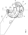
Fig. 1 shows a perspective view of an example of a scaffolding coupler which is connected to a ledger pipe end; -
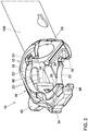
Fig. 2 shows a perspective view of the example ofFig. 1 from another point of view; -
Fig. 3 shows a perspective view of the example ofFig. 1 from yet another point of view; -
Fig. 4 shows an exploded perspective view of the example of the scaffolding coupler ofFig. 1 ; -
Fig. 5 shows an exploded perspective view of the example of the scaffolding coupler ofFig. 1 from another point of view; -
Fig. 6 shows a cross-sectional view of the example represented inFig. 1 , with the bent pin in opened position; -
Fig. 7 shows a cross-sectional view similar to that ofFig. 6 , with the bent pin in closed position and the scaffolding coupler placed on a standard; -
Fig. 8 shows an example of a standard of an embodiment of the scaffolding system; -
Fig. 9 shows a perspective view of a ledger connecting zone of the standard ofFig. 8 with a ledger connected thereto with a scaffolding coupler according to the example ofFigs. 1-7 ; -
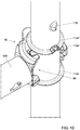
Fig. 10 shows a perspective view of the assembly ofFig. 9 from another point of view; -
Fig. 11 shows a perspective view similar to that shown inFig. 9 , with a second ledger connected to the standard; -
Fig. 12 shows a perspective view similar to that shown inFig. 10 , with a third ledger connected to the standard; -
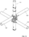
Fig. 13 shows a perspective view similar to that shown inFig. 9 , with a fourth ledger connected to the standard; -
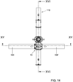
Fig. 14 shows a side view of the assembly of a standard with four ledgers shown inFig. 13 ; -
Fig. 15 shows cross section XV-XV ofFig. 14 ; and -
Fig. 16 shows cross section XVI-XVI ofFig. 14 . -
Figs. 1-7 show an example of a scaffolding coupler in which various embodiments as described in the subclaims are embodied. It is noted that the embodiments can also be utilized independently of each other and that the invention is not limited to the example shown in the figures. In the following, various embodiments will be described, while, with the aid of reference numerals, reference is made to the figures. The reference numerals are herein used for clarification but have no limitative effect. An embodiment can also be configured in another manner than represented in the example shown in the figures. - In the most general terms, the invention provides a
scaffolding coupler 10 intended for fixed connection to the ends of aledger 100 of a scaffolding system, for instance by means of a welded joint. The scaffolding system comprises in any case ledgers 100 andstandards 110. An example of an embodiment of a standard 110 is shown inFig. 8 . Each standard 110 comprises anelongate pipe wall 112 with a longitudinal central axis Ls. The cross section of thepipe wall 112 of thestandards 110 is usually circular. This also holds true for the cross section of theledgers 100. Each standard 110 further comprises a number of supportingprojections 114 which extend in tangential direction of thepipe wall 112 and which are formed through plastic deformation of thepipe wall 112. Each supportingprojection 114 comprises, viewed tangentially to thepipe wall 112, with the standard 110 in vertical orientation, a number of alternately arranged raisedparts 114a and loweredparts 114b. - The
scaffolding coupler 10 which is intended for such a scaffolding system comprises afoot 12 having afirst side 14 that is configured for fixed connection to a ledger pipe end 102 of afirst ledger 100. A second side of thefoot 12, located opposite thefirst side 14, forms apipe support surface 16 for abutment against thepipe wall 112 of a standard 110 or other ledger. Ahook 18 is integrally connected with thefoot 12. Thehook 18 has a radial insidecontour 20 which is substantially circular segmental. Thescaffolding coupler 10 further has at least one supportingsurface 22, 22' which is formed by thefoot 12 and thehook 18 and which, with thescaffolding coupler 10 connected to a standard 110, rests on a supportingsurface 114 of the respective standard 110 (seeFig. 16 ). The supportingsurface 22, 22' is provided with at least onerecess 24, 24' which is configured for receiving a raisedpart 114a of this supportingprojection 114 for tangential orientation of thescaffolding coupler 10 relative to the standard 110. In the example shown, the scaffolding coupler comprises two such supportingsurfaces 22, 22', a first supportingsurface 22 and an opposite, second supporting surface 22'. When thescaffolding coupler 10 rests with the first supportingsurface 22 on a supportingprojection 114, the second supporting surface 22' faces up. When thescaffolding coupler 10 rests with the second supporting surface 22' on a supportingprojection 114, the first supportingsurface 22 faces up. The provision of two such supportingsurfaces 22 therefore enables theledger 100 to be connected to a standard 110 in two manners. - The
scaffolding coupler 10 further comprises apin 26 which is slideably connected to thehook 18. Characteristically, thepin 26 is a bent pin, comprising a substantially circular segmentalinside contour 28 which is located on a radial inside of thebent pin 26, and which, in use, abuts directly against apipe wall 112 of a standard 110 or a ledger to be coupled to thefirst ledger 100. Thebent pin 26 has a substantially circular segmentaloutside contour 30 which is on a radial outside of thebent pin 26 and which abuts against the substantially circular segmentalinside contour 20 of thehook 18. Theinside contour 28 of thebent pin 26 together with thefoot supporting surface 16 define apipe receiving space 32 having a longitudinal central axis Lc which, in coupled condition with a standard 110 orledger 100, substantially coincides with a longitudinal central axis Ls of this standard or ledger. Theinside contour 28 and theoutside contour 30 of thepin 26 are oriented relative to each other such that, viewed from a firstfree end 34 to a secondfree end 36 of thepin 26, a radial thickness of thebent pin 26 gradually increases. Thebent pin 26 is received in thehook 18 so as to be tangentially slideable. The gradual increase of the radial thickness is preferably so gradual that the bent pin is self-locking. This implies that once it is struck in place, it does not slip loose of itself or under the influence of vibrations anymore. Only when the pin is struck loose again with, for instance, a hammer, is the pin returned to the releasing position and can the scaffolding coupler be removed from a pipe received in thepipe receiving space 32. - In one embodiment, of which an example is shown in the figures, the
bent pin 26 can be fork-shaped at a firstfree end 34 and can comprise twofork teeth fork recess 42 with a particular height H1. Here, theinside contour 20 of thehook 18 can comprise a back 44 extending in tangential direction and having a height H2 which is such that the back 44 is received substantially fittingly in thefork recess 42 so that, viewed in the direction of the longitudinal central axis Lc of thepipe receiving space 32, thebent pin 26 is fixed relative to thehook 18. - Through the use of a
single back 44 on thehook 18, and twofork teeth hook 18, still, a maximum total height of thepin 26 can be provided. The total height of thehook 18 must be as limited as possible, to allow the height of the ledger connecting zone to be as limited as possible. Thus, the thickness of a scaffolding floor assembly, formed by longitudinal ledgers, transverse ledgers and floor parts, can be as minimal as possible, so that in the scaffolding, an optimal passage between the successive floors of the scaffolding is obtained. If the pin is not of forked design, it needs to be enclosed both at the top and at the bottom by a wall part of the hook in order to provide vertical fixation of the pin relative to the hook. These two wall parts, which each contribute to the total height of the hook, can be omitted in the present embodiment, because with asingle back 44, the vertical fixation of thepin 26 relative to thehook 18 is provided. As a result, the combined height of thefork teeth pin 26 has a larger abutting surface which engages thepipe wall 112 of the standard 110. Owing to this larger abutting surface, the forces transmitted by thepin 26 on thepipe wall 112 are distributed better, and damages to thepipe wall 112 of the standard 110 occur less readily. In other words, the scaffolding coupler according to the embodiment with fork-shapedbent pin 26 can transmit greater forces without damaging thestandards 110 and therefore leads to a relatively stronger scaffolding system. - In one embodiment, of which an example is shown in the figures, the
bent pin 26 can comprise, at thesecond end 36 thereof on the radial outside, an integrally connected engagingprojection 46 which extends radially outwards from the radialoutside contour 30, while thehook 18 is provided with arecess 48 extending in tangential direction, through which recess reaches the engagingprojection 46 of thebent pin 26. - With the conventional scaffolding coupler comprising a wedge or pin, the pin is secured by striking one free end of the pin with a hammer and it is loosened by striking the other free end of the pin with a hammer. This implies that when mounting the known scaffolding coupler provided with a pin, the pin must be accessible to a hammer on both sides. In some cases, this is quite difficult to realize and leads to limitations to the possibilities of scaffolding erection. The engaging
projection 46 according to the above described embodiment has the advantage that both for securing and for loosening thebent pin 26 with a hammer, the same engagingprojection 46 can be struck with a hammer. The scaffolder will therefore be sure that he can release thepin 26 of the scaffolding coupler because, as the engagingprojection 46 thereof was accessible to a hammer when thescaffolding coupler 10 was being mounted, this engagingprojection 46 will also be accessible to a hammer upon demounting of thescaffolding coupler 10. - In an embodiment of the scaffolding system, of which an example is shown in the figures (see, for instance,
Figs. 9-16 ), in addition to the supportingprojections 114, thestandards 110 can also comprise retainingprojections 116 provided in thepipe wall 112 through plastic deformation. Here, with each supportingprojection 114, at least one retainingprojection 116 can be associated, while the retainingprojection 116 is arranged, with the standard 110 in vertical orientation, above the supportingprojection 114 associated therewith. - For such a scaffolding system, an embodiment of the
scaffolding coupler 10, of which an example is shown in the figures, can comprise abent pin 26 having atop surface 50 and abottom surface 52. With thescaffolding coupler 10 mounted on a standard 110, thetop surface 50 engages an underside of the retainingprojection 116 associated with the supportingprojection 114 on which rests the scaffolding coupler 10 (seeFig. 9 ), so that the scaffolding coupler is confined between the supportingprojection 114 and the associated retainingprojection 116. What is prevented in this manner is that theledger 10 with thescaffolding coupler 10 connected thereto tilts away from the standard, even when thebent pin 26 is not yet secured. Therefore, a scaffolder can first place aledger 10, then let go of it, for instance to grab a hammer, and only then strike in place the bent pin of the twoscaffolding couplers 10 of therespective ledger 100. As thescaffolding coupler 10 is confined between the supportingprojection 114 and the associated retainingprojection 116, theledger 100 remains in place. - In an embodiment, of which an example is shown in the figures, when the longitudinal central axis Lc of the
pipe receiving space 32 is in vertical orientation, viewed from thefirst end 34 of thepin 26 to thesecond end 36 of thepin 26, thetop surface 50 and thebottom surface 52 of thebent pin 26 can each, at an equal angle to a plane perpendicular to the central axis Lc, extend away from each other in wedge-shape configuration for forming an ascending surface. When striking thebent pin 26 in place, as a result of the obliquely orientedtop surface 50 of thepin 26, designed as ascending surface, thescaffolding coupler 10 is clamped in vertical direction between the supportingprojection 114 and the retainingprojection 116. Thebottom surface 52 of the pin is also designed as ascending surface, so that the same effect is also obtained when the scaffolding coupler is placed the other way around on a standard 110. This provides for an even more rigid connection between therespective scaffolding coupler 10 and the standard 110 as well as for a more accurate positioning of thescaffolding coupler 10 on the standard 110. - In an embodiment, of which an example is shown in the figures, at a radially outward facing part, the
hook 18 can comprise astop projection 54 which is integrally connected with thehook 18. Thestop projection 54 is positioned on thehook 18 such that, when connecting to a standard 110 a first and asecond ledger 100, 100' that are each in line with each other and each rest on the same supportingprojection 114 of the standard 110, thefoot 12 of thescaffolding coupler 10 of thefirst ledger 100 engages the stop projection 54' of the scaffolding coupler 10' of the second ledger 100' and vice versa (seeFig. 15 ). Owing to the presence of thestop projections 54, 54', the orientation of the first and thesecond ledger 100, 100' relative to each other is not exclusively defined by tangential orientation of thefirst ledger 100 and the second ledger 100' relative to the standard 110 through cooperation of the profiled supportingprojection 114 withrecesses 24 in the supportingsurfaces 22 of the twoscaffolding couplers 10, 10', but this mutual orientation is also defined by the mutual engagement of thescaffolding couplers 10, 10' of each other via thestop projections 54, 54'. As a result, the alignedledgers stop projection 54 of onescaffolding coupler 10 abuts against the other scaffolding coupler 10' and vice versa, two alignedledgers 100, 100' in effect form one rigid whole, acting as a single, continuous pipe. This leads to a more rigid construction of the scaffolding as a whole. - In an embodiment, of which an example is shown in the figures, a distance between the
top surface 50 and thebottom surface 52 of thepin 26, i.e., the height H3 (seeFig. 16 ) of thepin 26, can be at least 14 mm. In one embodiment, a distance between the mutually facing surfaces of thefork teeth fork teeth - In one embodiment, of which an example is shown in the figures, near the
foot 12, thescaffolding coupler 10 may be provided with arecess 56 which is configured for receiving a free end of the hook 18' and the first end 34' of the pin 26' of a second scaffolding coupler 10' of the same type when this second scaffolding coupler 10' rests on the same supportingprojection 114 of a standard 110 as therespective scaffolding coupler 10. As a result, ledgers 100, 100' can be connected to a standard 110 in line with each other at the same height. - As already indicated above, the invention also relates to a scaffolding system. In the most general terms, such a scaffolding system comprises
standards 110 and ledgers 100. At least one of thestandards 110 of the scaffolding system comprises anelongate pipe wall 112 having a central longitudinal axis Ls and a number of supportingprojections 114 extending substantially in tangential direction of thepipe wall 112, which have been formed by plastic deformation of thepipe wall 112. Each supportingprojection 114 comprises, viewed in a tangential direction of thepipe wall 112, when the standard 110 is vertically oriented, a number of alternately arranged raisedparts 114a and loweredparts 114b. At least one of theledgers 100 of the scaffolding system comprises at least at one of the ends 102 ascaffolding coupler 10 according to the invention. - In an embodiment of the scaffolding system according to the invention, of which an example is shown in the figures, each standard 110, in addition to the above-mentioned supporting
projections 114, can further comprise retainingprojections 116 provided in thestandard pipe wall 112 through plastic deformation. Here, with each supportingprojection 114, at least one retainingprojection 116 is associated. When the standard 110 is vertically oriented, in this embodiment, the retainingprojection 116 is provided above the supportingprojection 114 associated therewith. - Owing to the presence of the retaining
projection 116, aledger 100 can be placed on a standard 110 and continues to sit in this position without thepins 26 of the twoscaffolding couplers 10 of theledger 100 being secured. The ledger's falling out is prevented by thehooks 18 hooking under the retainingprojections 116 of the twostandards 110. This provides a great advantage in erecting scaffolding. - In one embodiment of the scaffolding system, of which an example is shown in the figures, the scaffolding couplers of the ledgers can each comprise a
stop projection 54 which is integrally connected with thehook 18 on a radially outwardly facing part thereof, while thestop projection 54 is positioned on thehook 18 such that, when connecting a first and asecond ledger 100, 100' to a standard 110, with the first and the second ledger being in line with each other and each resting on the same supportingprojection 114 of the standard 110, thefoot 12 of thescaffolding coupler 10 of thefirst ledger 100 engages the stop projection 54' of the scaffolding coupler 10' of the second ledger 100' and vice versa. That engagement is such that the orientation of the first and thesecond ledger 100, 100' relative to each other is not exclusively defined by tangential orientation of thefirst ledger 100 and the second ledger 100' relative to the standard 110 through cooperation of the profiled supportingprojection 114 withrecesses 24 in the supportingsurfaces 22 of the twoscaffolding couplers 10, 10', but also by the mutual engagement of thescaffolding couplers 10, 10' via thestop projections 54, 54'. Moreover, the positioning of thestop projections 54, 54' is such that thefirst ledger 100 and the second ledger 100' substantially behave as a single continuous pipe. - In one embodiment of the scaffolding system, of which an example is shown in the figures, each standard 110 can comprise, at regular distances, a
ledger connecting zone 118, while in each ledger connecting zone 118 a first supportingprojection 114 of the type mentioned is provided for connecting to the standard 110 ofledgers 100, 100' which extend in a first direction and in eachledger connecting zone 118, at a small distance above this first supportingprojection 114, the standard comprises a second supporting projection 114' of the type mentioned for connecting to the standard ofledgers 100", 100'" which extend in a second direction. - An example of a thus configured standard 110 is clearly visible in
Figures 8-16 . - In an embodiment, of which an example is shown in the figures, the slight distance between the two supporting
projections 114, 114' in aledger connecting zone 118 of the standard 110 is as small as possible, but sufficient to place on the lower supportingprojection 114 at least onescaffolding coupler 10 without this interfering, upon placement, with the upper supporting projection 114'. - As the mutual distance between the two supporting
projections 114, 114' within aledger connecting zone 118 is kept minimal, the height of a scaffolding floor assembly, which comprises longitudinal ledgers, transverse ledgers and floor parts, is as small as possible. Thus, the passage between two floors of a scaffolding is obstructed as little as possible. - In an embodiment of the scaffolding system, of which an example is shown in the figures, the regular distance Dp between successive
ledger connecting zones 118 may be at least 25 cm and at most 70 cm. Owing to this relatively small distance, in erecting the scaffolding, a large flexibility is obtained with respect to the positioning of theledgers 100 on thestandards 110. This allows scaffoldings to be erected for many applications. - The various embodiments described above can be applied independently of each other and combined with each other in various manners. The reference numerals in the detailed description and the claims do not limit the description of the embodiments and the claims and serve for clarification only.
Claims (13)
- A scaffolding coupler (10) intended for fixed attachment to the ends of a ledger (100) of a scaffolding system, wherein the scaffolding system comprises standards (110) and ledgers (100), wherein each standard (110) comprises:• an elongate pipe wall (112) with a central longitudinal axis (Ls); and• a number of supporting projections (114) extending substantially in tangential direction of the pipe wall (112) which are formed through plastic deformation of the pipe wall (112), each supporting projection (114), viewed in a tangential direction of the pipe wall (112), when the standard (110) is vertically oriented, comprising a number of alternately arranged raised parts (114a) and lowered parts (114b);wherein the scaffolding coupler (10) comprises:• a foot (12) which has a first side (14) which is configured for the fixed connection with a ledger pipe end (102) of a first ledger (100), a second side of the foot (12), which lies opposite the first side, forming a pipe support surface (16) for abutment against the pipe wall (112) of a standard (110) or ledger;• a hook (18) which is integrally connected with the foot (12), the hook (18) having a radial inside contour (20) which is substantially circular segmental;• at least one supporting surface (22) which is formed by the foot (12) and the hook (18) and which in the connected condition of the scaffolding coupler (10) with a standard (110) rests on said supporting projection (114) of the respective standard (110), the supporting surface (22) being provided with at least one recess (24) which is configured for receiving a raised part (114a) of this supporting projection (114) for tangential orientation of the scaffolding coupler (10) relative to the standard (110);• a pin (26) which is slideably connected with the hook (18);characterized in that the pin (26) is a bent pin, which is provided with a substantially circular segmental inside contour (28) located on a radial inside of the bent pin (26), and which, in use, abuts directly against a pipe wall (112) of a standard (110) to be coupled to the first ledger (100) or a ledger, wherein the bent pin (26) has a substantially circular segmental outside contour (30) which is located on a radial outside of the bent pin (26) and which abuts against the substantially circular segmental inside contour (20) of the hook (18), while the inside contour (28) of the bent pin (26) together with the pipe support surface (16) define a pipe receiving space (32) having a central longitudinal axis (Lc) which in coupled condition with a standard (110) or ledger (100) substantially coincides with a central longitudinal axis (Ls) of such standard or ledger, the inside contour (28) and the outside contour (30) of the pin (26) being oriented relative to each other such that a radial thickness of the bent pin (26) viewed from a first free end (34) towards a second free end (36) of the pin (26) gradually increases, the bent pin (26) being received in the hook (18) in a manner slideable in tangential direction.
- The scaffolding coupler according to claim 1, wherein the bent pin (26) near the first free end (34) thereof is of fork-shaped configuration and comprises two fork teeth (38, 40) between which extends a fork recess (42) having a particular height (H1), wherein the inside contour (20) of the hook (18) comprises a back (44) extending in tangential direction, having a height (H2) which is such that the back (44) is received substantially fittingly in the fork recess (42), such that the bent pin (26), viewed in the direction of the central longitudinal axis (Lc) of the pipe receiving space (32), is fixed relative to the hook (18).
- The scaffolding coupler according to claim 1 or 2, wherein the bent pin (26) near the second end (36) thereof comprises on the radial outside an integrally connected engaging projection (46) which extends from the radial outside contour (30) radially outward, the hook (18) being provided with a recess (48) extending in tangential direction, through which reaches the engaging projection (46) of the bent pin (26).
- The scaffolding coupler according to any one of claims 1-3, intended for a scaffolding system whose standards (110) in addition to said supporting projections (114) also comprise retaining projections (116) arranged in the pipe wall (112) through plastic deformation, each supporting projection (114) having associated with it at least one retaining projection (116), the retaining projection (116) being arranged, when the standard (110) is vertically oriented, above the associated supporting projection (114), the bent pin (26) having a top surface (50) and a bottom surface (52), the top surface (50) in mounted condition of the scaffolding coupler (10) on a standard (110) engaging a lower side of the retaining projection (116) which is associated with the supporting projection (114) on which rests the scaffolding coupler (10), such that the scaffolding coupler is confined between the supporting projection (114) and the associated retaining projection (116).
- The scaffolding coupler according to claim 4, wherein the top surface (50) and the bottom surface (52) of the bent pin (26), with the central longitudinal axis (Lc) of the pipe receiving space (32) in vertical orientation, viewed from the first end (34) of the pin (26) to the second end (36) of the pin (26), each at an equal angle to a plane perpendicular to the central axis (Lc), extend away from each other in wedge-shaped configuration for forming an ascending surface, wherein, upon striking the bent pin (26) in place, as a result of the obliquely oriented top surface (50) of the pin (26) designed as ascending surface, the scaffolding coupler (10) is clamped in vertical direction between the supporting projection (114) and the retaining projection (116).
- The scaffolding coupler according to claim 2, wherein the bent pin (26), with the central axis (Lc) of the pipe receiving space (32) in a vertical orientation, has a top surface (50) and a bottom surface (52), wherein a distance between the top surface (50) and the bottom surface (52), that is, the height (H3) of the pin (26), is at least 14 mm and wherein a distance between mutually facing surfaces of the fork teeth (38, 40), that is, the height of the fork recess (H1), is at least 4 mm and at most 8 mm, while the fork teeth (38, 40), viewed in the direction of the central axis (Lc) of the pipe receiving space, have a height (H4) which is at least 5 mm.
- The scaffolding coupler according to any one of the preceding claims, wherein the respective scaffolding coupler (10) near the foot (12) is provided with a recess (56) which is configured for receiving a free end of the hook (18') and the first end (34') of the pin (26') of a second scaffolding coupler (10') of the same type when this second scaffolding coupler (10') rests on the same supporting projection (114) of a standard (110) as the respective scaffolding coupler (10).
- A scaffolding system comprising standards (110) and ledgers (100), wherein at least one of the standards (110) comprises:• an elongate pipe wall (112) with a central longitudinal axis (Lc); and• a number of supporting projections (114) extending substantially in tangential direction of the pipe wall (112) which are formed through plastic deformation of the pipe wall (112), each supporting projection (114), viewed in a tangential direction of the pipe wall (112), when the standard (110) is vertically oriented, comprising a number of alternately arranged raised parts (114a) and lowered parts (114b);wherein at least one of the ledgers (100) at at least one of the ends (102) comprises:• a scaffolding coupler (10) according to any one of claims 1-7.
- The scaffolding system according to claim 8, wherein each standard (110) in addition to said supporting projections (114) also comprises retaining projections (116) arranged in the standard pipe wall through plastic deformation, each supporting projection (114) having associated with it at least one retaining projection (116), the retaining projection (116) being arranged, when the standard (110) is vertically oriented, above the associated supporting projection (114).
- The scaffolding system according to claim 8 or 9, wherein each standard (110) at regular distances comprises ledger connecting zones (118), while in each ledger connecting zone (118) a first supporting projection (114) of said type is provided for connection of ledgers (100, 100') with the standard (110) that extend in a first direction, and in each ledger connecting zone (118) at a small distance above such first supporting projection (114) the standard comprises a second supporting projection (114') of said type for connection of ledgers (100", 100'") with a standard that extend in a second direction.
- The scaffolding system according to claim 10, wherein the slight distance between the two supporting projections (114, 114') in a ledger connecting zone (118) of the standard (110) is as small as possible, but is sufficient to place on the lower supporting projection (114) at least one scaffolding coupler (10) without this interfering, upon placement, with the upper supporting projection (114').
- The scaffolding system according to any one of claims 9-11, wherein the regular distance (Dp) between successive ledger connecting zones (118) is at least 25 cm and at most 70 cm.
- The scaffolding system according to any one of claims 9-12, wherein the scaffolding couplers of the ledgers are each provided with a stop projection (54) which is integrally connected with the hook (18) on a radially outwardly facing part thereof, wherein the stop projection (54) is positioned on the hook (18) such that upon connection of a first and a second ledger (100, 100') with a standard (110), where the first and the second ledger are in line with each other and each rest on the same supporting projection (114) of the standard (110), the foot (12) of the scaffolding coupler (10) of the first ledger (100) engages the stop projection (54') of the scaffolding coupler (10') of the second ledger (100') and vice versa, such that the orientation of the first and the second ledger (100, 100') relative to each other is not exclusively defined by tangential orientation of the first ledger (100) and the second ledger (100') relative to the standard (110) through cooperation of the profiled supporting projection (114) with recesses (24) in the supporting surfaces (22) of the two scaffolding couplers (10, 10'), but also by the mutual engagement of the scaffolding couplers (10, 10') via said stop projections (54, 54') and such that the first ledger (100) and the second ledger (100') substantially behave like a single continuous pipe.
Applications Claiming Priority (2)
| Application Number | Priority Date | Filing Date | Title |
|---|---|---|---|
| NL2012924A NL2012924B1 (en) | 2014-06-02 | 2014-06-02 | Scaffolding coupling as well as scaffolding system. |
| PCT/NL2015/050392 WO2015187010A1 (en) | 2014-06-02 | 2015-06-02 | Scaffolding coupler, standard and scaffolding system |
Publications (2)
| Publication Number | Publication Date |
|---|---|
| EP3149259A1 EP3149259A1 (en) | 2017-04-05 |
| EP3149259B1 true EP3149259B1 (en) | 2018-12-12 |
Family
ID=51846893
Family Applications (1)
| Application Number | Title | Priority Date | Filing Date |
|---|---|---|---|
| EP15732968.1A Active EP3149259B1 (en) | 2014-06-02 | 2015-06-02 | Scaffolding coupler and scaffolding system |
Country Status (6)
| Country | Link |
|---|---|
| US (1) | US10119279B2 (en) |
| EP (1) | EP3149259B1 (en) |
| CN (1) | CN106715810B (en) |
| ES (1) | ES2715020T3 (en) |
| NL (1) | NL2012924B1 (en) |
| WO (1) | WO2015187010A1 (en) |
Families Citing this family (8)
| Publication number | Priority date | Publication date | Assignee | Title |
|---|---|---|---|---|
| ES2587453B1 (en) * | 2015-03-17 | 2017-08-01 | Ayudame A Ayudarte S.L | ARTICULATED REMOVABLE MODULAR SIZE |
| US10570633B2 (en) * | 2017-11-16 | 2020-02-25 | Titan Formwork Systems Llc | System for lateral support of shoring posts |
| CA3006922A1 (en) * | 2018-06-01 | 2019-12-01 | At-Pac China Business Trust | Scaffold ledger |
| KR101942939B1 (en) | 2018-07-27 | 2019-01-28 | 목포대학교산학협력단 | Use of the broken coupler testing device on the scaffold and the breaking test method of the scaffold |
| CN108978480A (en) * | 2018-08-18 | 2018-12-11 | 吴江市明港道桥工程有限公司 | A kind of highway bridge scaffold |
| NL2033195B1 (en) * | 2022-09-30 | 2024-04-08 | Scafom Holding B V | Wind-up protection system, floor part, scaffolding, and use |
| EP4379169B1 (en) * | 2022-12-03 | 2025-07-23 | Marius Perseke | Vertical frame system for a system frame |
| US20240254784A1 (en) * | 2023-01-26 | 2024-08-01 | Adelie, Llc | Clamp assembly for scaffolding |
Family Cites Families (9)
| Publication number | Priority date | Publication date | Assignee | Title |
|---|---|---|---|---|
| JP3860864B2 (en) * | 1996-09-13 | 2006-12-20 | 株式会社有弘メンテナンス | Hook devices such as scaffolding boards |
| JPH11131793A (en) * | 1997-10-29 | 1999-05-18 | Daisan:Kk | Fire striking members for temporary scaffolds |
| AU2002319895A1 (en) * | 2002-06-04 | 2003-12-19 | Rajkrishan Fakirchand Sharma | Improved in scaffold connections |
| JP2004278262A (en) * | 2003-03-13 | 2004-10-07 | Minoru Sato | Stopper metal fitting of scaffold board for temporary scaffold and stopper pin |
| NL2003206C2 (en) * | 2009-07-15 | 2011-01-18 | Scafom Internat B V | Scaffolding system, as well as coupling, girder tube and standing tube intended for such a scaffolding system. |
| NL2006450C2 (en) * | 2011-03-22 | 2012-09-25 | Scafom Internat B V | Standard and ledger of a scaffolding system, and method for erecting the same. |
| FR2984430A1 (en) * | 2011-12-19 | 2013-06-21 | Lp Tent | Connection part for assembling post to cross-piece to realize reinforcement of e.g. tent used for cultural events, has elastic element placed between latch and body and acting such that latch is maintained in left position normally |
| CN202706522U (en) * | 2012-07-31 | 2013-01-30 | 开平创誉棚架设备有限公司 | Connecting fastener |
| CN202882397U (en) * | 2012-10-16 | 2013-04-17 | 郑其雄 | Pitch point connecting structure of scaffold |
-
2014
- 2014-06-02 NL NL2012924A patent/NL2012924B1/en not_active IP Right Cessation
-
2015
- 2015-06-02 ES ES15732968T patent/ES2715020T3/en active Active
- 2015-06-02 EP EP15732968.1A patent/EP3149259B1/en active Active
- 2015-06-02 WO PCT/NL2015/050392 patent/WO2015187010A1/en not_active Ceased
- 2015-06-02 US US15/315,751 patent/US10119279B2/en active Active
- 2015-06-02 CN CN201580029638.0A patent/CN106715810B/en active Active
Non-Patent Citations (1)
| Title |
|---|
| None * |
Also Published As
| Publication number | Publication date |
|---|---|
| US20170121986A1 (en) | 2017-05-04 |
| EP3149259A1 (en) | 2017-04-05 |
| CN106715810B (en) | 2019-07-12 |
| WO2015187010A1 (en) | 2015-12-10 |
| ES2715020T3 (en) | 2019-05-31 |
| NL2012924B1 (en) | 2016-06-09 |
| CN106715810A (en) | 2017-05-24 |
| US10119279B2 (en) | 2018-11-06 |
Similar Documents
| Publication | Publication Date | Title |
|---|---|---|
| EP3149259B1 (en) | Scaffolding coupler and scaffolding system | |
| US9133634B2 (en) | Scaffolding system, as well as a coupling, a ledger and a standard | |
| US8978823B2 (en) | Arrangement of a scaffolding component and of a vertical scaffolding element | |
| KR101213439B1 (en) | A clamp for the euro-form, and a support system of a beam form using the same | |
| KR101581540B1 (en) | Connector for steel pipe scaffold | |
| AU2021424267B2 (en) | Arrangement of scaffolding components | |
| US9683380B2 (en) | Standard and ledger of a scaffolding system, and method for erecting the same | |
| KR100997243B1 (en) | Prefabricated Clubs for Construction | |
| EP3714115B1 (en) | Device for strengthening and rigging trusses and method in which such device is applied | |
| JP4637431B2 (en) | Device for joining scaffold elements | |
| EP2766541B1 (en) | Coupling member for scaffoldings | |
| AU2015263826A1 (en) | A joiner | |
| KR101994312B1 (en) | A scaffold for architecture | |
| US20220010569A1 (en) | Scaffolding post connection rosette with hollow embossments of reduced nominal thickness, and scaffolding subassembly | |
| KR101004204B1 (en) | Horizontal connector for steel pipe scaffolding | |
| RU2799968C2 (en) | Joint in the form of a sockets of reduced nominal thickness intended for scaffold posts and equipped with hollow stamped bosses and scaffold assembly | |
| EP3772559B1 (en) | Anchoring system with diagonal bracing and formwork strut | |
| CA2742051A1 (en) | Scaffold post sleeve | |
| JP4674724B2 (en) | Manhole connecting bracket and manhole using this manhole connecting bracket | |
| AU2024276407A1 (en) | Railing bar for a scaffold and method for erecting a scaffold | |
| KR102060885B1 (en) | Assembly type handrail | |
| KR20250001349U (en) | Horizontal material for system scaffolding | |
| ZA201006642B (en) | Cross bracing attachment member |
Legal Events
| Date | Code | Title | Description |
|---|---|---|---|
| STAA | Information on the status of an ep patent application or granted ep patent |
Free format text: STATUS: THE INTERNATIONAL PUBLICATION HAS BEEN MADE |
|
| PUAI | Public reference made under article 153(3) epc to a published international application that has entered the european phase |
Free format text: ORIGINAL CODE: 0009012 |
|
| STAA | Information on the status of an ep patent application or granted ep patent |
Free format text: STATUS: REQUEST FOR EXAMINATION WAS MADE |
|
| 17P | Request for examination filed |
Effective date: 20161230 |
|
| AK | Designated contracting states |
Kind code of ref document: A1 Designated state(s): AL AT BE BG CH CY CZ DE DK EE ES FI FR GB GR HR HU IE IS IT LI LT LU LV MC MK MT NL NO PL PT RO RS SE SI SK SM TR |
|
| AX | Request for extension of the european patent |
Extension state: BA ME |
|
| DAV | Request for validation of the european patent (deleted) | ||
| DAX | Request for extension of the european patent (deleted) | ||
| STAA | Information on the status of an ep patent application or granted ep patent |
Free format text: STATUS: EXAMINATION IS IN PROGRESS |
|
| 17Q | First examination report despatched |
Effective date: 20171122 |
|
| GRAP | Despatch of communication of intention to grant a patent |
Free format text: ORIGINAL CODE: EPIDOSNIGR1 |
|
| STAA | Information on the status of an ep patent application or granted ep patent |
Free format text: STATUS: GRANT OF PATENT IS INTENDED |
|
| INTG | Intention to grant announced |
Effective date: 20180702 |
|
| GRAS | Grant fee paid |
Free format text: ORIGINAL CODE: EPIDOSNIGR3 |
|
| GRAA | (expected) grant |
Free format text: ORIGINAL CODE: 0009210 |
|
| STAA | Information on the status of an ep patent application or granted ep patent |
Free format text: STATUS: THE PATENT HAS BEEN GRANTED |
|
| AK | Designated contracting states |
Kind code of ref document: B1 Designated state(s): AL AT BE BG CH CY CZ DE DK EE ES FI FR GB GR HR HU IE IS IT LI LT LU LV MC MK MT NL NO PL PT RO RS SE SI SK SM TR |
|
| REG | Reference to a national code |
Ref country code: GB Ref legal event code: FG4D |
|
| REG | Reference to a national code |
Ref country code: CH Ref legal event code: EP |
|
| REG | Reference to a national code |
Ref country code: AT Ref legal event code: REF Ref document number: 1076169 Country of ref document: AT Kind code of ref document: T Effective date: 20181215 |
|
| REG | Reference to a national code |
Ref country code: DE Ref legal event code: R096 Ref document number: 602015021309 Country of ref document: DE |
|
| REG | Reference to a national code |
Ref country code: IE Ref legal event code: FG4D |
|
| REG | Reference to a national code |
Ref country code: SE Ref legal event code: TRGR |
|
| REG | Reference to a national code |
Ref country code: NL Ref legal event code: FP |
|
| REG | Reference to a national code |
Ref country code: LT Ref legal event code: MG4D |
|
| PG25 | Lapsed in a contracting state [announced via postgrant information from national office to epo] |
Ref country code: BG Free format text: LAPSE BECAUSE OF FAILURE TO SUBMIT A TRANSLATION OF THE DESCRIPTION OR TO PAY THE FEE WITHIN THE PRESCRIBED TIME-LIMIT Effective date: 20190312 Ref country code: HR Free format text: LAPSE BECAUSE OF FAILURE TO SUBMIT A TRANSLATION OF THE DESCRIPTION OR TO PAY THE FEE WITHIN THE PRESCRIBED TIME-LIMIT Effective date: 20181212 Ref country code: LT Free format text: LAPSE BECAUSE OF FAILURE TO SUBMIT A TRANSLATION OF THE DESCRIPTION OR TO PAY THE FEE WITHIN THE PRESCRIBED TIME-LIMIT Effective date: 20181212 Ref country code: NO Free format text: LAPSE BECAUSE OF FAILURE TO SUBMIT A TRANSLATION OF THE DESCRIPTION OR TO PAY THE FEE WITHIN THE PRESCRIBED TIME-LIMIT Effective date: 20190312 Ref country code: FI Free format text: LAPSE BECAUSE OF FAILURE TO SUBMIT A TRANSLATION OF THE DESCRIPTION OR TO PAY THE FEE WITHIN THE PRESCRIBED TIME-LIMIT Effective date: 20181212 Ref country code: LV Free format text: LAPSE BECAUSE OF FAILURE TO SUBMIT A TRANSLATION OF THE DESCRIPTION OR TO PAY THE FEE WITHIN THE PRESCRIBED TIME-LIMIT Effective date: 20181212 |
|
| REG | Reference to a national code |
Ref country code: AT Ref legal event code: MK05 Ref document number: 1076169 Country of ref document: AT Kind code of ref document: T Effective date: 20181212 |
|
| PG25 | Lapsed in a contracting state [announced via postgrant information from national office to epo] |
Ref country code: AL Free format text: LAPSE BECAUSE OF FAILURE TO SUBMIT A TRANSLATION OF THE DESCRIPTION OR TO PAY THE FEE WITHIN THE PRESCRIBED TIME-LIMIT Effective date: 20181212 Ref country code: GR Free format text: LAPSE BECAUSE OF FAILURE TO SUBMIT A TRANSLATION OF THE DESCRIPTION OR TO PAY THE FEE WITHIN THE PRESCRIBED TIME-LIMIT Effective date: 20190313 Ref country code: RS Free format text: LAPSE BECAUSE OF FAILURE TO SUBMIT A TRANSLATION OF THE DESCRIPTION OR TO PAY THE FEE WITHIN THE PRESCRIBED TIME-LIMIT Effective date: 20181212 |
|
| PG25 | Lapsed in a contracting state [announced via postgrant information from national office to epo] |
Ref country code: PL Free format text: LAPSE BECAUSE OF FAILURE TO SUBMIT A TRANSLATION OF THE DESCRIPTION OR TO PAY THE FEE WITHIN THE PRESCRIBED TIME-LIMIT Effective date: 20181212 Ref country code: PT Free format text: LAPSE BECAUSE OF FAILURE TO SUBMIT A TRANSLATION OF THE DESCRIPTION OR TO PAY THE FEE WITHIN THE PRESCRIBED TIME-LIMIT Effective date: 20190412 Ref country code: CZ Free format text: LAPSE BECAUSE OF FAILURE TO SUBMIT A TRANSLATION OF THE DESCRIPTION OR TO PAY THE FEE WITHIN THE PRESCRIBED TIME-LIMIT Effective date: 20181212 Ref country code: IT Free format text: LAPSE BECAUSE OF FAILURE TO SUBMIT A TRANSLATION OF THE DESCRIPTION OR TO PAY THE FEE WITHIN THE PRESCRIBED TIME-LIMIT Effective date: 20181212 |
|
| PG25 | Lapsed in a contracting state [announced via postgrant information from national office to epo] |
Ref country code: IS Free format text: LAPSE BECAUSE OF FAILURE TO SUBMIT A TRANSLATION OF THE DESCRIPTION OR TO PAY THE FEE WITHIN THE PRESCRIBED TIME-LIMIT Effective date: 20190412 Ref country code: RO Free format text: LAPSE BECAUSE OF FAILURE TO SUBMIT A TRANSLATION OF THE DESCRIPTION OR TO PAY THE FEE WITHIN THE PRESCRIBED TIME-LIMIT Effective date: 20181212 Ref country code: SK Free format text: LAPSE BECAUSE OF FAILURE TO SUBMIT A TRANSLATION OF THE DESCRIPTION OR TO PAY THE FEE WITHIN THE PRESCRIBED TIME-LIMIT Effective date: 20181212 Ref country code: SM Free format text: LAPSE BECAUSE OF FAILURE TO SUBMIT A TRANSLATION OF THE DESCRIPTION OR TO PAY THE FEE WITHIN THE PRESCRIBED TIME-LIMIT Effective date: 20181212 Ref country code: EE Free format text: LAPSE BECAUSE OF FAILURE TO SUBMIT A TRANSLATION OF THE DESCRIPTION OR TO PAY THE FEE WITHIN THE PRESCRIBED TIME-LIMIT Effective date: 20181212 |
|
| REG | Reference to a national code |
Ref country code: DE Ref legal event code: R097 Ref document number: 602015021309 Country of ref document: DE |
|
| PLBE | No opposition filed within time limit |
Free format text: ORIGINAL CODE: 0009261 |
|
| STAA | Information on the status of an ep patent application or granted ep patent |
Free format text: STATUS: NO OPPOSITION FILED WITHIN TIME LIMIT |
|
| PG25 | Lapsed in a contracting state [announced via postgrant information from national office to epo] |
Ref country code: AT Free format text: LAPSE BECAUSE OF FAILURE TO SUBMIT A TRANSLATION OF THE DESCRIPTION OR TO PAY THE FEE WITHIN THE PRESCRIBED TIME-LIMIT Effective date: 20181212 Ref country code: DK Free format text: LAPSE BECAUSE OF FAILURE TO SUBMIT A TRANSLATION OF THE DESCRIPTION OR TO PAY THE FEE WITHIN THE PRESCRIBED TIME-LIMIT Effective date: 20181212 Ref country code: SI Free format text: LAPSE BECAUSE OF FAILURE TO SUBMIT A TRANSLATION OF THE DESCRIPTION OR TO PAY THE FEE WITHIN THE PRESCRIBED TIME-LIMIT Effective date: 20181212 |
|
| 26N | No opposition filed |
Effective date: 20190913 |
|
| PG25 | Lapsed in a contracting state [announced via postgrant information from national office to epo] |
Ref country code: MC Free format text: LAPSE BECAUSE OF FAILURE TO SUBMIT A TRANSLATION OF THE DESCRIPTION OR TO PAY THE FEE WITHIN THE PRESCRIBED TIME-LIMIT Effective date: 20181212 |
|
| REG | Reference to a national code |
Ref country code: CH Ref legal event code: PL |
|
| REG | Reference to a national code |
Ref country code: BE Ref legal event code: MM Effective date: 20190630 |
|
| PG25 | Lapsed in a contracting state [announced via postgrant information from national office to epo] |
Ref country code: TR Free format text: LAPSE BECAUSE OF FAILURE TO SUBMIT A TRANSLATION OF THE DESCRIPTION OR TO PAY THE FEE WITHIN THE PRESCRIBED TIME-LIMIT Effective date: 20181212 |
|
| PG25 | Lapsed in a contracting state [announced via postgrant information from national office to epo] |
Ref country code: IE Free format text: LAPSE BECAUSE OF NON-PAYMENT OF DUE FEES Effective date: 20190602 |
|
| PG25 | Lapsed in a contracting state [announced via postgrant information from national office to epo] |
Ref country code: LI Free format text: LAPSE BECAUSE OF NON-PAYMENT OF DUE FEES Effective date: 20190630 Ref country code: LU Free format text: LAPSE BECAUSE OF NON-PAYMENT OF DUE FEES Effective date: 20190602 Ref country code: BE Free format text: LAPSE BECAUSE OF NON-PAYMENT OF DUE FEES Effective date: 20190630 Ref country code: CH Free format text: LAPSE BECAUSE OF NON-PAYMENT OF DUE FEES Effective date: 20190630 |
|
| PG25 | Lapsed in a contracting state [announced via postgrant information from national office to epo] |
Ref country code: CY Free format text: LAPSE BECAUSE OF FAILURE TO SUBMIT A TRANSLATION OF THE DESCRIPTION OR TO PAY THE FEE WITHIN THE PRESCRIBED TIME-LIMIT Effective date: 20181212 |
|
| PG25 | Lapsed in a contracting state [announced via postgrant information from national office to epo] |
Ref country code: MT Free format text: LAPSE BECAUSE OF FAILURE TO SUBMIT A TRANSLATION OF THE DESCRIPTION OR TO PAY THE FEE WITHIN THE PRESCRIBED TIME-LIMIT Effective date: 20181212 Ref country code: HU Free format text: LAPSE BECAUSE OF FAILURE TO SUBMIT A TRANSLATION OF THE DESCRIPTION OR TO PAY THE FEE WITHIN THE PRESCRIBED TIME-LIMIT; INVALID AB INITIO Effective date: 20150602 |
|
| PG25 | Lapsed in a contracting state [announced via postgrant information from national office to epo] |
Ref country code: MK Free format text: LAPSE BECAUSE OF FAILURE TO SUBMIT A TRANSLATION OF THE DESCRIPTION OR TO PAY THE FEE WITHIN THE PRESCRIBED TIME-LIMIT Effective date: 20181212 |
|
| PGFP | Annual fee paid to national office [announced via postgrant information from national office to epo] |
Ref country code: DE Payment date: 20250618 Year of fee payment: 11 |
|
| PGFP | Annual fee paid to national office [announced via postgrant information from national office to epo] |
Ref country code: GB Payment date: 20250618 Year of fee payment: 11 |
|
| PGFP | Annual fee paid to national office [announced via postgrant information from national office to epo] |
Ref country code: NL Payment date: 20250618 Year of fee payment: 11 |
|
| PGFP | Annual fee paid to national office [announced via postgrant information from national office to epo] |
Ref country code: FR Payment date: 20250625 Year of fee payment: 11 |
|
| PGFP | Annual fee paid to national office [announced via postgrant information from national office to epo] |
Ref country code: SE Payment date: 20250618 Year of fee payment: 11 |
|
| PGFP | Annual fee paid to national office [announced via postgrant information from national office to epo] |
Ref country code: ES Payment date: 20250728 Year of fee payment: 11 |