EP3149259B1 - Élément d'assemblage d'échafaudage et système d'échafaudage - Google Patents
Élément d'assemblage d'échafaudage et système d'échafaudage Download PDFInfo
- Publication number
- EP3149259B1 EP3149259B1 EP15732968.1A EP15732968A EP3149259B1 EP 3149259 B1 EP3149259 B1 EP 3149259B1 EP 15732968 A EP15732968 A EP 15732968A EP 3149259 B1 EP3149259 B1 EP 3149259B1
- Authority
- EP
- European Patent Office
- Prior art keywords
- scaffolding
- standard
- ledger
- projection
- pin
- Prior art date
- Legal status (The legal status is an assumption and is not a legal conclusion. Google has not performed a legal analysis and makes no representation as to the accuracy of the status listed.)
- Active
Links
Images





Classifications
-
- E—FIXED CONSTRUCTIONS
- E04—BUILDING
- E04G—SCAFFOLDING; FORMS; SHUTTERING; BUILDING IMPLEMENTS OR AIDS, OR THEIR USE; HANDLING BUILDING MATERIALS ON THE SITE; REPAIRING, BREAKING-UP OR OTHER WORK ON EXISTING BUILDINGS
- E04G7/00—Connections between parts of the scaffold
- E04G7/30—Scaffolding bars or members with non-detachably fixed coupling elements
- E04G7/302—Scaffolding bars or members with non-detachably fixed coupling elements for connecting crossing or intersecting bars or members
- E04G7/306—Scaffolding bars or members with non-detachably fixed coupling elements for connecting crossing or intersecting bars or members the added coupling elements are fixed at several bars or members to connect
- E04G7/307—Scaffolding bars or members with non-detachably fixed coupling elements for connecting crossing or intersecting bars or members the added coupling elements are fixed at several bars or members to connect with tying means for connecting the bars or members
-
- E—FIXED CONSTRUCTIONS
- E04—BUILDING
- E04G—SCAFFOLDING; FORMS; SHUTTERING; BUILDING IMPLEMENTS OR AIDS, OR THEIR USE; HANDLING BUILDING MATERIALS ON THE SITE; REPAIRING, BREAKING-UP OR OTHER WORK ON EXISTING BUILDINGS
- E04G1/00—Scaffolds primarily resting on the ground
- E04G1/02—Scaffolds primarily resting on the ground composed essentially of members elongated in one dimension [1D] only, e.g. poles, lattice masts, with or without end portions of special form, connected together by any means
- E04G1/04—Scaffolds primarily resting on the ground composed essentially of members elongated in one dimension [1D] only, e.g. poles, lattice masts, with or without end portions of special form, connected together by any means the members being exclusively poles, rods, beams, or other members of similar form and simple cross-section
- E04G1/06—Scaffolds primarily resting on the ground composed essentially of members elongated in one dimension [1D] only, e.g. poles, lattice masts, with or without end portions of special form, connected together by any means the members being exclusively poles, rods, beams, or other members of similar form and simple cross-section comprising members with rod-like or tubular portions fitting together end to end, with or without separate connecting pieces
-
- E—FIXED CONSTRUCTIONS
- E04—BUILDING
- E04G—SCAFFOLDING; FORMS; SHUTTERING; BUILDING IMPLEMENTS OR AIDS, OR THEIR USE; HANDLING BUILDING MATERIALS ON THE SITE; REPAIRING, BREAKING-UP OR OTHER WORK ON EXISTING BUILDINGS
- E04G1/00—Scaffolds primarily resting on the ground
- E04G1/02—Scaffolds primarily resting on the ground composed essentially of members elongated in one dimension [1D] only, e.g. poles, lattice masts, with or without end portions of special form, connected together by any means
- E04G1/12—Scaffolds primarily resting on the ground composed essentially of members elongated in one dimension [1D] only, e.g. poles, lattice masts, with or without end portions of special form, connected together by any means comprising members of special, e.g. composite, cross-section or with lugs or the like or lateral apertures for supporting or attaching other members
-
- E—FIXED CONSTRUCTIONS
- E04—BUILDING
- E04G—SCAFFOLDING; FORMS; SHUTTERING; BUILDING IMPLEMENTS OR AIDS, OR THEIR USE; HANDLING BUILDING MATERIALS ON THE SITE; REPAIRING, BREAKING-UP OR OTHER WORK ON EXISTING BUILDINGS
- E04G7/00—Connections between parts of the scaffold
- E04G7/30—Scaffolding bars or members with non-detachably fixed coupling elements
- E04G7/301—Scaffolding bars or members with non-detachably fixed coupling elements for connecting bars or members which are parallel or in end-to-end relation
-
- E—FIXED CONSTRUCTIONS
- E04—BUILDING
- E04G—SCAFFOLDING; FORMS; SHUTTERING; BUILDING IMPLEMENTS OR AIDS, OR THEIR USE; HANDLING BUILDING MATERIALS ON THE SITE; REPAIRING, BREAKING-UP OR OTHER WORK ON EXISTING BUILDINGS
- E04G7/00—Connections between parts of the scaffold
- E04G7/30—Scaffolding bars or members with non-detachably fixed coupling elements
- E04G7/32—Scaffolding bars or members with non-detachably fixed coupling elements with coupling elements using wedges
Definitions
- the invention relates to a scaffolding coupler which is fixedly connected with the ends of a ledger and serves for coupling the ledger to a standard or to another ledger.
- the invention further relates to a scaffolding system comprising standards and ledgers.
- WO2012/128630 relates to a scaffolding system of the type where the standards comprise supporting projections which are formed through plastic deformation of the pipe wall of the standard.
- the ledgers comprise couplers with the aid of which a ledger can be attached to a standard, whereby the coupling rests on a supporting projection of the standard in a ledger connecting zone of this standard.
- the projections are provided through plastic deformation of the pipe wall, they do not lead to weight increase of the standard, as is the case with scaffolding systems where the standards comprise annular flanges.
- the supporting projections and hence the ledger can be disposed at a smaller distance from each other than the mutual distance customary with annular flanges.
- each supporting projection can support two scaffolding couplers, so that two aligned ledgers can be connected to the standard.
- a scaffolding system comprises at least two standards, longitudinal ledgers and transverse ledgers.
- a drawback of the system described in WO2012/128630 resides in the couplers of transverse ledgers resting on the couplers of the longitudinal ledgers which in turn rest on a supporting projection, or the other way around.
- longitudinal ledgers should be used too, because otherwise there is nowhere to rest the transverse ledgers that have to be connected to the standards. In some cases, this leads to placement of a larger number of longitudinal ledgers than required from a viewpoint of strength and rigidity of the entire scaffolding.
- the additional longitudinal ledgers are only necessary for supporting the scaffolding couplers of the transverse ledgers. The consequences are that it takes longer to erect the scaffolding and that a larger amount of longitudinal ledgers is required for erecting the scaffolding. Both consequences lead to high costs of the scaffolding, which is undesired.
- the scaffolding coupler known from WO2012/128630 which discloses the features of the preamble of claim 1, comprises four parts, a first casting comprising a foot and a hook integrally connected therewith, a securing element, a hinge pin with the aid of which the securing element is pivotally connected to the hook, and a wedge which is slideably received in a wedge opening in the hook.
- This scaffolding coupler requires several mounting operations in order to be assembled. Due to the four parts and the mounting operations, the known scaffolding coupler is relatively expensive.
- the invention contemplates a scaffolding coupler which, while maintaining the above described advantages of the known scaffolding coupler, remedies the above described disadvantages of the known scaffolding coupler at least in part. It should be noted that the above described disadvantages and problems have been recognized by the inventor and therefore do not form part of the state of the art. More particularly, the object of the invention is a scaffolding coupler which consists of fewer parts and hence can be manufactured at a lower cost price.
- the invention provides a scaffolding coupler intended for fixed attachment to the ends of a ledger of a scaffolding system, wherein the scaffolding system comprises standards and ledgers, wherein each standard comprises:
- the scaffolding coupler therefore consists of only two parts, i.e., a first part comprising the foot and the hook and a second part which is formed by the bent pin. In one embodiment, both parts can also be configured as a casting or forging. Such a scaffolding coupler consisting of only two parts can be manufactured relatively inexpensively.
- the bent pin provides for clamping of the scaffolding coupler on a scaffolding pipe to which the scaffolding coupler is connected. The gradual increase in thickness of the pin is such that this is self-locking, which means that, once it has been struck into place, the bent pin cannot become detached by vibrations. Only by actively striking the bent pin loose can the bent pin be brought into the releasing condition, so that the scaffolding coupler can be taken from the pipe again. Further embodiments of the scaffolding coupler are described in the subclaims and will be further elucidated in the following on the basis of an example with reference to the figures.
- the invention also provides a scaffolding system comprising standards and ledgers, wherein at least one of the standards comprises:
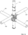
- Such a scaffolding system offers the advantage that the scaffolding couplers of the transverse ledgers do not rest on the scaffolding couplers of the longitudinal ledgers or the other way around. Instead, the scaffolding couplers of the longitudinal ledgers have, in each ledger connecting zone, their own associated supporting projection on the standard and the scaffolding couplers of the transverse ledgers have, in each ledger connecting zone, their own associated supporting projection on the standard. Consequently, there is no need to place longitudinal ledgers which are not necessary from a viewpoint of strength and rigidity of the scaffolding, but which would only be placed to provide a supporting surface for the scaffolding couplers of the transverse ledgers. Erecting scaffolding can thus be realized faster and with fewer ledgers than with the scaffolding known from WO2012/128630 .
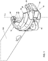
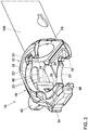
- Figs. 1-7 show an example of a scaffolding coupler in which various embodiments as described in the subclaims are embodied. It is noted that the embodiments can also be utilized independently of each other and that the invention is not limited to the example shown in the figures.
- various embodiments will be described, while, with the aid of reference numerals, reference is made to the figures. The reference numerals are herein used for clarification but have no limitative effect. An embodiment can also be configured in another manner than represented in the example shown in the figures.
- the invention provides a scaffolding coupler 10 intended for fixed connection to the ends of a ledger 100 of a scaffolding system, for instance by means of a welded joint.
- the scaffolding system comprises in any case ledgers 100 and standards 110.
- An example of an embodiment of a standard 110 is shown in Fig. 8 .
- Each standard 110 comprises an elongate pipe wall 112 with a longitudinal central axis Ls.
- the cross section of the pipe wall 112 of the standards 110 is usually circular. This also holds true for the cross section of the ledgers 100.
- Each standard 110 further comprises a number of supporting projections 114 which extend in tangential direction of the pipe wall 112 and which are formed through plastic deformation of the pipe wall 112.
- Each supporting projection 114 comprises, viewed tangentially to the pipe wall 112, with the standard 110 in vertical orientation, a number of alternately arranged raised parts 114a and lowered parts 114b.
- the scaffolding coupler 10 which is intended for such a scaffolding system comprises a foot 12 having a first side 14 that is configured for fixed connection to a ledger pipe end 102 of a first ledger 100.
- a hook 18 is integrally connected with the foot 12.
- the hook 18 has a radial inside contour 20 which is substantially circular segmental.
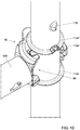
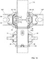
- the scaffolding coupler 10 further has at least one supporting surface 22, 22' which is formed by the foot 12 and the hook 18 and which, with the scaffolding coupler 10 connected to a standard 110, rests on a supporting surface 114 of the respective standard 110 (see Fig. 16 ).
- the supporting surface 22, 22' is provided with at least one recess 24, 24' which is configured for receiving a raised part 114a of this supporting projection 114 for tangential orientation of the scaffolding coupler 10 relative to the standard 110.
- the scaffolding coupler comprises two such supporting surfaces 22, 22', a first supporting surface 22 and an opposite, second supporting surface 22'.
- the second supporting surface 22' faces up.
- the first supporting surface 22 faces up.
- the provision of two such supporting surfaces 22 therefore enables the ledger 100 to be connected to a standard 110 in two manners.
- the scaffolding coupler 10 further comprises a pin 26 which is slideably connected to the hook 18.
- the pin 26 is a bent pin, comprising a substantially circular segmental inside contour 28 which is located on a radial inside of the bent pin 26, and which, in use, abuts directly against a pipe wall 112 of a standard 110 or a ledger to be coupled to the first ledger 100.
- the bent pin 26 has a substantially circular segmental outside contour 30 which is on a radial outside of the bent pin 26 and which abuts against the substantially circular segmental inside contour 20 of the hook 18.
- the inside contour 28 of the bent pin 26 together with the foot supporting surface 16 define a pipe receiving space 32 having a longitudinal central axis Lc which, in coupled condition with a standard 110 or ledger 100, substantially coincides with a longitudinal central axis Ls of this standard or ledger.
- the inside contour 28 and the outside contour 30 of the pin 26 are oriented relative to each other such that, viewed from a first free end 34 to a second free end 36 of the pin 26, a radial thickness of the bent pin 26 gradually increases.
- the bent pin 26 is received in the hook 18 so as to be tangentially slideable.
- the gradual increase of the radial thickness is preferably so gradual that the bent pin is self-locking.
- the bent pin 26 can be fork-shaped at a first free end 34 and can comprise two fork teeth 38, 40 between which extends a fork recess 42 with a particular height H1.
- the inside contour 20 of the hook 18 can comprise a back 44 extending in tangential direction and having a height H2 which is such that the back 44 is received substantially fittingly in the fork recess 42 so that, viewed in the direction of the longitudinal central axis Lc of the pipe receiving space 32, the bent pin 26 is fixed relative to the hook 18.
- a maximum total height of the pin 26 can be provided.
- the total height of the hook 18 must be as limited as possible, to allow the height of the ledger connecting zone to be as limited as possible.
- the thickness of a scaffolding floor assembly formed by longitudinal ledgers, transverse ledgers and floor parts, can be as minimal as possible, so that in the scaffolding, an optimal passage between the successive floors of the scaffolding is obtained. If the pin is not of forked design, it needs to be enclosed both at the top and at the bottom by a wall part of the hook in order to provide vertical fixation of the pin relative to the hook.
- the bent pin 26 can comprise, at the second end 36 thereof on the radial outside, an integrally connected engaging projection 46 which extends radially outwards from the radial outside contour 30, while the hook 18 is provided with a recess 48 extending in tangential direction, through which recess reaches the engaging projection 46 of the bent pin 26.
- the engaging projection 46 has the advantage that both for securing and for loosening the bent pin 26 with a hammer, the same engaging projection 46 can be struck with a hammer.
- the scaffolder will therefore be sure that he can release the pin 26 of the scaffolding coupler because, as the engaging projection 46 thereof was accessible to a hammer when the scaffolding coupler 10 was being mounted, this engaging projection 46 will also be accessible to a hammer upon demounting of the scaffolding coupler 10.
- the standards 110 can also comprise retaining projections 116 provided in the pipe wall 112 through plastic deformation.
- the retaining projection 116 can be associated, while the retaining projection 116 is arranged, with the standard 110 in vertical orientation, above the supporting projection 114 associated therewith.
- an embodiment of the scaffolding coupler 10 can comprise a bent pin 26 having a top surface 50 and a bottom surface 52.
- the top surface 50 engages an underside of the retaining projection 116 associated with the supporting projection 114 on which rests the scaffolding coupler 10 (see Fig. 9 ), so that the scaffolding coupler is confined between the supporting projection 114 and the associated retaining projection 116. What is prevented in this manner is that the ledger 10 with the scaffolding coupler 10 connected thereto tilts away from the standard, even when the bent pin 26 is not yet secured.
- a scaffolder can first place a ledger 10, then let go of it, for instance to grab a hammer, and only then strike in place the bent pin of the two scaffolding couplers 10 of the respective ledger 100.
- the ledger 100 remains in place.
- the top surface 50 and the bottom surface 52 of the bent pin 26 can each, at an equal angle to a plane perpendicular to the central axis Lc, extend away from each other in wedge-shape configuration for forming an ascending surface.
- the scaffolding coupler 10 is clamped in vertical direction between the supporting projection 114 and the retaining projection 116.
- the bottom surface 52 of the pin is also designed as ascending surface, so that the same effect is also obtained when the scaffolding coupler is placed the other way around on a standard 110. This provides for an even more rigid connection between the respective scaffolding coupler 10 and the standard 110 as well as for a more accurate positioning of the scaffolding coupler 10 on the standard 110.
- the hook 18 can comprise a stop projection 54 which is integrally connected with the hook 18.
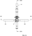
- the stop projection 54 is positioned on the hook 18 such that, when connecting to a standard 110 a first and a second ledger 100, 100' that are each in line with each other and each rest on the same supporting projection 114 of the standard 110, the foot 12 of the scaffolding coupler 10 of the first ledger 100 engages the stop projection 54' of the scaffolding coupler 10' of the second ledger 100' and vice versa (see Fig. 15 ).
- the orientation of the first and the second ledger 100, 100' relative to each other is not exclusively defined by tangential orientation of the first ledger 100 and the second ledger 100' relative to the standard 110 through cooperation of the profiled supporting projection 114 with recesses 24 in the supporting surfaces 22 of the two scaffolding couplers 10, 10', but this mutual orientation is also defined by the mutual engagement of the scaffolding couplers 10, 10' of each other via the stop projections 54, 54'.
- the aligned ledgers 100, 100' and 100", 100'" will have hardly any clearance relative to each other, so that a scaffolding as a whole forms a more rigid and stable construction.
- two aligned ledgers 100, 100' in effect form one rigid whole, acting as a single, continuous pipe. This leads to a more rigid construction of the scaffolding as a whole.
- a distance between the top surface 50 and the bottom surface 52 of the pin 26, i.e., the height H3 (see Fig. 16 ) of the pin 26, can be at least 14 mm.
- a distance between the mutually facing surfaces of the fork teeth 38, 40, i.e., the height of the fork recess H1 can be at least 4 mm and at most 8 mm.
- the fork teeth 38, 40 viewed in the direction of the central axis Lc of the pipe receiving space, can have a height H4 which is at least 5 mm.
- the scaffolding coupler 10 may be provided with a recess 56 which is configured for receiving a free end of the hook 18' and the first end 34' of the pin 26' of a second scaffolding coupler 10' of the same type when this second scaffolding coupler 10' rests on the same supporting projection 114 of a standard 110 as the respective scaffolding coupler 10.
- ledgers 100, 100' can be connected to a standard 110 in line with each other at the same height.
- the invention also relates to a scaffolding system.
- a scaffolding system comprises standards 110 and ledgers 100.
- At least one of the standards 110 of the scaffolding system comprises an elongate pipe wall 112 having a central longitudinal axis Ls and a number of supporting projections 114 extending substantially in tangential direction of the pipe wall 112, which have been formed by plastic deformation of the pipe wall 112.
- Each supporting projection 114 comprises, viewed in a tangential direction of the pipe wall 112, when the standard 110 is vertically oriented, a number of alternately arranged raised parts 114a and lowered parts 114b.
- At least one of the ledgers 100 of the scaffolding system comprises at least at one of the ends 102 a scaffolding coupler 10 according to the invention.
- each standard 110 in addition to the above-mentioned supporting projections 114, can further comprise retaining projections 116 provided in the standard pipe wall 112 through plastic deformation.
- each supporting projection 114 at least one retaining projection 116 is associated.
- the retaining projection 116 is provided above the supporting projection 114 associated therewith.
- a ledger 100 can be placed on a standard 110 and continues to sit in this position without the pins 26 of the two scaffolding couplers 10 of the ledger 100 being secured.
- the ledger's falling out is prevented by the hooks 18 hooking under the retaining projections 116 of the two standards 110. This provides a great advantage in erecting scaffolding.
- the scaffolding couplers of the ledgers can each comprise a stop projection 54 which is integrally connected with the hook 18 on a radially outwardly facing part thereof, while the stop projection 54 is positioned on the hook 18 such that, when connecting a first and a second ledger 100, 100' to a standard 110, with the first and the second ledger being in line with each other and each resting on the same supporting projection 114 of the standard 110, the foot 12 of the scaffolding coupler 10 of the first ledger 100 engages the stop projection 54' of the scaffolding coupler 10' of the second ledger 100' and vice versa.
- That engagement is such that the orientation of the first and the second ledger 100, 100' relative to each other is not exclusively defined by tangential orientation of the first ledger 100 and the second ledger 100' relative to the standard 110 through cooperation of the profiled supporting projection 114 with recesses 24 in the supporting surfaces 22 of the two scaffolding couplers 10, 10', but also by the mutual engagement of the scaffolding couplers 10, 10' via the stop projections 54, 54'. Moreover, the positioning of the stop projections 54, 54' is such that the first ledger 100 and the second ledger 100' substantially behave as a single continuous pipe.
- each standard 110 can comprise, at regular distances, a ledger connecting zone 118, while in each ledger connecting zone 118 a first supporting projection 114 of the type mentioned is provided for connecting to the standard 110 of ledgers 100, 100' which extend in a first direction and in each ledger connecting zone 118, at a small distance above this first supporting projection 114, the standard comprises a second supporting projection 114' of the type mentioned for connecting to the standard of ledgers 100", 100'" which extend in a second direction.
- the slight distance between the two supporting projections 114, 114' in a ledger connecting zone 118 of the standard 110 is as small as possible, but sufficient to place on the lower supporting projection 114 at least one scaffolding coupler 10 without this interfering, upon placement, with the upper supporting projection 114'.
- a scaffolding floor assembly which comprises longitudinal ledgers, transverse ledgers and floor parts, is as small as possible.
- the passage between two floors of a scaffolding is obstructed as little as possible.
- the regular distance Dp between successive ledger connecting zones 118 may be at least 25 cm and at most 70 cm. Owing to this relatively small distance, in erecting the scaffolding, a large flexibility is obtained with respect to the positioning of the ledgers 100 on the standards 110. This allows scaffoldings to be erected for many applications.
Landscapes
- Engineering & Computer Science (AREA)
- Architecture (AREA)
- Mechanical Engineering (AREA)
- Civil Engineering (AREA)
- Structural Engineering (AREA)
- Chemical & Material Sciences (AREA)
- Composite Materials (AREA)
- Mutual Connection Of Rods And Tubes (AREA)
- Bridges Or Land Bridges (AREA)
Claims (13)
- Coupleur d'échafaudage (10) destiné à un attachement fixe sur les extrémités d'un longeron (100) d'un système d'échafaudage, dans lequel le système d'échafaudage comprend des échasses (110) et des longerons (100), dans lequel chaque échasse (110) comprend :une paroi de tube (112) allongée avec un axe longitudinal central (Ls) ; etun certain nombre de saillies de support (114) s'étendant sensiblement dans une direction tangentielle de la paroi de tube (112) qui sont formées par déformation plastique de la paroi de tube (112), chaque saillie de support (114), vue dans une direction tangentielle de la paroi de tube (112), quand l'échasse (110) est orientée verticalement, comprenant un certain nombre de parties surélevées (114a) et de parties abaissées (114b) agencées alternativement ;dans lequel le coupleur d'échafaudage (10) comprend :un pied (12) qui comporte un premier côté (14) qui est configuré pour la connexion fixe avec une extrémité de tube de longeron (102) d'un premier longeron (100), un second côté du pied (12), qui repose à l'opposé du premier côté, formant une surface de support de tube (16) pour venir en butée contre la paroi de tube (112) d'une échasse (110) ou d'un longeron ;un crochet (18) qui est connecté d'un seul bloc avec le pied (12), le crochet (18) ayant un contour intérieur radial (20) qui est un segment sensiblement circulaire ;au moins une surface de support (22) qui est formée par le pied (12) et le crochet (18) et qui dans l'état connecté du coupleur d'échafaudage (10) avec une échasse (110) repose sur ladite saillie de support (114) de ladite échasse (110) respective, la surface de support (22) étant pourvue d'au moins un évidement (24) qui est configuré pour recevoir une partie surélevée (114a) de cette saillie de support (114) pour une orientation tangentielle du coupleur d'échafaudage (10) relativement à l'échasse (110) ;un axe (26) qui est connecté de manière coulissante avec le crochet (18) ;caractérisé en ce que l'axe (26) est un axe courbé, qui est pourvu d'un contour intérieur (28) en segment sensiblement circulaire situé sur un intérieur radial de l'axe courbé (26), et qui, en utilisation, vient en butée directement contre une paroi de tube (112) d'une échasse (110) pour être couplé au premier longeron (100) ou à un longeron, dans lequel l'axe courbé (26) a un contour extérieur (30) en segment sensiblement circulaire qui est situé sur un extérieur radial de l'axe courbé (26) et qui vient en butée contre le contour intérieur (20) en segment sensiblement circulaire du crochet (18), alors que le contour intérieur (28) de l'axe courbé (26) conjointement avec la surface de support de tube (16) définit un espace de réception de tube (32) ayant un axe longitudinal central (Lc) qui dans un état couplé avec une échasse (110) ou un longeron (100) coïncide sensiblement avec un axe longitudinal central (Ls) d'une telle échasse ou d'un tel longeron, le contour intérieur (28) et le contour extérieur (30) de l'axe (26) étant orientés relativement l'un à l'autre de telle manière qu'une épaisseur radiale de l'axe courbé (26) vue depuis une première extrémité libre (34) vers une seconde extrémité libre (36) de l'axe (26) augmente progressivement, l'axe courbé (26) étant reçu dans le crochet (18) d'une manière coulissante dans une direction tangentielle.
- Coupleur d'échafaudage selon la revendication 1, dans lequel l'axe courbé (26) près de la première extrémité libre (34) de celui-ci a une configuration en forme de fourche et comprend deux dents de fourche (38, 40) entre lesquelles s'étend un évidement de fourche (42) ayant une hauteur particulière (H1), dans lequel le contour intérieur (20) du crochet (18) comprend un arrière (44) s'étendant dans une direction tangentielle, ayant une hauteur (H2) qui est telle que l'arrière (44) est reçu sensiblement de manière ajustée dans l'évidement de fourche (42), de telle manière que l'axe courbé (26), vu dans la direction de l'axe longitudinal central (Lc) de l'espace de réception de tube (32), est fixe relativement au crochet (18).
- Coupleur d'échafaudage selon la revendication 1 ou 2, dans lequel l'axe courbé (26) près de la seconde extrémité (36) de celui-ci comprend sur l'extérieur radial une saillie de prise (46) connectée d'un seul bloc qui s'étend depuis le contour extérieur (30) radial radialement vers l'extérieur, le crochet (18) étant pourvu d'un évidement (48) s'étendant dans une direction tangentielle, par lequel il atteint la saillie de prise (46) de l'axe courbé (26).
- Coupleur d'échafaudage selon l'une quelconque des revendications 1-3, destiné à un système d'échafaudage dont les échasses (110) en plus desdites saillies de support (114) comprennent en outre des saillies de retenue (116) agencées dans la paroi de tube (112) par déformation plastique, chaque saillie de support (114) ayant associée avec elle au moins une saillie de retenue (116), la saillie de retenue (116) étant agencée, quand l'échasse (110) est orientée verticalement, au-dessus de la saillie de support (114) associée, l'axe courbé (26) ayant une surface supérieure (50) et une surface inférieure (52), la surface supérieure (50) dans un état monté du coupleur d'échafaudage (10) sur une échasse (110) venant en prise avec un côté inférieur de la saillie de retenue (116) qui est associée avec la saillie de support (114) sur laquelle repose le coupleur d'échafaudage (10), de telle manière que le coupleur d'échafaudage est confiné entre la saillie de support (114) et la saillie de retenue (116) associée.
- Coupleur d'échafaudage selon la revendication 4, dans lequel la surface supérieure (50) et la surface inférieure (52) de l'axe courbé (26), avec l'axe longitudinal central (Lc) de l'espace de réception de tube (32) dans une orientation verticale, vues depuis la première extrémité (34) de l'axe (26) vers la seconde extrémité (36) de l'axe (26), chacune à un angle égal à un plan perpendiculaire à l'axe central (Lc), s'étendent à distance l'une de l'autre dans une configuration en forme de coin pour former une surface montante, dans lequel quand on frappe l'axe courbé (26) en place, en résultat de la surface supérieure (50) orientée obliquement de l'axe (26) conçue comme une surface montante, le coupleur d'échafaudage (10) est serré dans la direction verticale entre la saillie de support (114) et la saillie de retenue (116).
- Coupleur d'échafaudage selon la revendication 2, dans lequel l'axe courbé (26), avec l'axe central (Lc) de l'espace de réception de tube (32) dans une orientation verticale, a une surface supérieure (50) et une surface inférieure (52), dans lequel une distance entre la surface supérieure (50) et la surface inférieure (52), c'est à dire, la hauteur (H3) de l'axe (26), est au moins de 14 mm et dans lequel une distance entre des surfaces mutuellement opposées des dents de fourche (38, 40), c'est à dire, la hauteur de l'évidement de fourche (H1), est au moins de 4 mm et au plus de 8 mm, alors que les dents de fourche (38, 40), vues dans la direction de l'axe central (Lc) de l'espace de réception de tube, ont une hauteur (H4) qui est au moins de 5 mm.
- Coupleur d'échafaudage selon l'une quelconque des revendications précédentes, dans lequel le coupleur d'échafaudage (10) respectif près du pied (12) est pourvu d'un évidement (56) qui est configuré pour recevoir une extrémité libre du crochet (18') et la première extrémité (34') de l'axe (26') d'un second coupleur d'échafaudage (10') du même type quand ce second coupleur d'échafaudage (10') repose sur la même saillie de support (114) d'une échasse (110) que le coupleur d'échafaudage (10) respectif.
- Système d'échafaudage comprenant des échasses (110) et des longerons (100), dans lequel chaque échasse (110) comprend :une paroi de tube (112) allongée avec un axe longitudinal central (Ls) ; etun certain nombre de saillies de support (114) s'étendant sensiblement dans une direction tangentielle de la paroi de tube (112) qui sont formées par déformation plastique de la paroi de tube (112), chaque saillie de support (114), vue dans une direction tangentielle de la paroi de tube (112), quand l'échasse (110) est orientée verticalement, comprenant un certain nombre de parties surélevées (114a) et de parties abaissées (114b) agencées alternativement ;dans lequel au moins un des longerons (100) en au moins une des extrémités (102) comprend :
un coupleur d'échafaudage (10) selon l'une quelconque des revendications 1-7. - Système d'échafaudage selon la revendication 8, dans lequel chaque échasse (110) en plus desdites saillies de support (114) comprend aussi des saillies de retenue (116) agencées dans la paroi de tube d'échasse par déformation plastique, chaque saillie de support (114) ayant associée à elle au moins une saillie de retenue (116), la saillie de retenue (116) étant agencée, quand l'échasse (110) est orientée verticalement, au-dessus de la saillie de support (114) associée.
- Système d'échafaudage selon la revendication 8 ou 9, dans lequel chaque échasse (110) à distances régulières comprend des zones de connexion de longeron (118), alors que dans chaque zone de connexion de longeron (118) une première saillie de support (114) dudit type est fournie pour connexion de longerons (100, 100') avec l'échasse (110) qui s'étend dans une première direction, et dans chaque zone de connexion de longeron (118) à une petite distance au-dessus d'une telle première saillie de support (114) l'échasse comprend une seconde saillie de support (114') dudit type pour connexion de longerons (100", 100"') avec une échasse qui s'étend dans une seconde direction.
- Système d'échafaudage selon la revendication 10, dans lequel la légère distance entre les deux saillies de support (114, 114') dans une zone de connexion de longeron (118) de l'échasse (110) est aussi petite que possible, mais est suffisante pour placer sur la saillie de support (114) inférieure au moins un coupleur d'échafaudage (10) sans que cela interfère, lors du placement, avec la saillie de support (114') supérieure.
- Système d'échafaudage selon l'une quelconque des revendications 9-11, dans lequel la distance régulière (Dp) entre des zones de connexion de longeron (118) successives est d'au moins 25 cm et d'au plus 70 cm.
- Système d'échafaudage selon l'une quelconque des revendications 9-12, dans lequel les coupleurs d'échafaudage des longerons sont chacun pourvus d'une saillie d'arrêt (54) qui est connectée d'un seul bloc avec le crochet (18) sur une partie faisant face radialement vers l'extérieur de celui-ci, dans lequel la saillie d'arrêt (54) est positionnée sur le crochet (18) de telle manière que lors de la connexion d'un premier et d'un second longerons (100, 100') avec une échasse (110), où le premier et le second longerons sont alignés ensemble et reposent chacun sur la même saillie de support (114) de l'échasse (110), le pied (12) du coupleur d'échafaudage (10) du premier longeron (100) vient en prise avec la saillie d'arrêt (54') du coupleur d'échafaudage (10') du second longeron (100') et vice versa, de telle manière que l'orientation du premier et du second longerons (100, 100') relativement l'un à l'autre n'est pas définie exclusivement par l'orientation tangentielle du premier longeron (100) et du second longeron (100') relativement à l'échasse (110) par coopération de la saillie de support (114) profilée avec des évidements (24) dans les surfaces de support (22) des deux coupleurs d'échafaudage (10, 10'), mais aussi par la prise mutuelle des coupleurs d'échafaudage (10, 10') via lesdites saillies d'arrêt (54, 54') et de telle manière que le premier longeron (100) et le second longeron (100') se comportent sensiblement comme un seul tube continu.
Applications Claiming Priority (2)
| Application Number | Priority Date | Filing Date | Title |
|---|---|---|---|
| NL2012924A NL2012924B1 (nl) | 2014-06-02 | 2014-06-02 | Steigerkoppeling alsmede steigersysteem. |
| PCT/NL2015/050392 WO2015187010A1 (fr) | 2014-06-02 | 2015-06-02 | Élément d'assemblage d'échafaudage, montant et système d'échafaudage |
Publications (2)
| Publication Number | Publication Date |
|---|---|
| EP3149259A1 EP3149259A1 (fr) | 2017-04-05 |
| EP3149259B1 true EP3149259B1 (fr) | 2018-12-12 |
Family
ID=51846893
Family Applications (1)
| Application Number | Title | Priority Date | Filing Date |
|---|---|---|---|
| EP15732968.1A Active EP3149259B1 (fr) | 2014-06-02 | 2015-06-02 | Élément d'assemblage d'échafaudage et système d'échafaudage |
Country Status (6)
| Country | Link |
|---|---|
| US (1) | US10119279B2 (fr) |
| EP (1) | EP3149259B1 (fr) |
| CN (1) | CN106715810B (fr) |
| ES (1) | ES2715020T3 (fr) |
| NL (1) | NL2012924B1 (fr) |
| WO (1) | WO2015187010A1 (fr) |
Families Citing this family (8)
| Publication number | Priority date | Publication date | Assignee | Title |
|---|---|---|---|---|
| ES2587453B1 (es) * | 2015-03-17 | 2017-08-01 | Ayudame A Ayudarte S.L | Andamio modular desmontable articulado |
| US10570633B2 (en) * | 2017-11-16 | 2020-02-25 | Titan Formwork Systems Llc | System for lateral support of shoring posts |
| CA3006922A1 (fr) * | 2018-06-01 | 2019-12-01 | At-Pac China Business Trust | Longeron d'echafaudage |
| KR101942939B1 (ko) | 2018-07-27 | 2019-01-28 | 목포대학교산학협력단 | 비계의 커플러 파단 시험 장치 및 이를 이용한 비계의 커플러 파단 시험 방법 |
| CN108978480A (zh) * | 2018-08-18 | 2018-12-11 | 吴江市明港道桥工程有限公司 | 一种公路桥梁用脚手架 |
| NL2033195B1 (nl) * | 2022-09-30 | 2024-04-08 | Scafom Holding B V | Opwaaibeveiligingssysteem, vloerdeel, steiger, en gebruik |
| EP4379169B1 (fr) * | 2022-12-03 | 2025-07-23 | Marius Perseke | Système de cadre vertical pour échafaudage de système |
| US20240254784A1 (en) * | 2023-01-26 | 2024-08-01 | Adelie, Llc | Clamp assembly for scaffolding |
Family Cites Families (9)
| Publication number | Priority date | Publication date | Assignee | Title |
|---|---|---|---|---|
| JP3860864B2 (ja) * | 1996-09-13 | 2006-12-20 | 株式会社有弘メンテナンス | 足場板等のフック装置 |
| JPH11131793A (ja) * | 1997-10-29 | 1999-05-18 | Daisan:Kk | 仮設足場用火打ち部材 |
| AU2002319895A1 (en) * | 2002-06-04 | 2003-12-19 | Rajkrishan Fakirchand Sharma | Improved in scaffold connections |
| JP2004278262A (ja) * | 2003-03-13 | 2004-10-07 | Minoru Sato | 仮設足場用足場板掛金のストッパー金具及びストッパーピン |
| NL2003206C2 (nl) * | 2009-07-15 | 2011-01-18 | Scafom Internat B V | Steigersysteem, alsmede koppeling, liggerbuis en staanderbuis bestemd voor een dergelijk steigersysteem. |
| NL2006450C2 (en) * | 2011-03-22 | 2012-09-25 | Scafom Internat B V | Standard and ledger of a scaffolding system, and method for erecting the same. |
| FR2984430A1 (fr) * | 2011-12-19 | 2013-06-21 | Lp Tent | Piece de connexion pour des elements allonges, et ensemble d'elements allonges dont au moins deux sont chacun equipes d'une telle piece |
| CN202706522U (zh) * | 2012-07-31 | 2013-01-30 | 开平创誉棚架设备有限公司 | 一种连接扣件 |
| CN202882397U (zh) * | 2012-10-16 | 2013-04-17 | 郑其雄 | 一种脚手架节点连接结构 |
-
2014
- 2014-06-02 NL NL2012924A patent/NL2012924B1/nl not_active IP Right Cessation
-
2015
- 2015-06-02 ES ES15732968T patent/ES2715020T3/es active Active
- 2015-06-02 EP EP15732968.1A patent/EP3149259B1/fr active Active
- 2015-06-02 WO PCT/NL2015/050392 patent/WO2015187010A1/fr not_active Ceased
- 2015-06-02 US US15/315,751 patent/US10119279B2/en active Active
- 2015-06-02 CN CN201580029638.0A patent/CN106715810B/zh active Active
Non-Patent Citations (1)
| Title |
|---|
| None * |
Also Published As
| Publication number | Publication date |
|---|---|
| US20170121986A1 (en) | 2017-05-04 |
| EP3149259A1 (fr) | 2017-04-05 |
| CN106715810B (zh) | 2019-07-12 |
| WO2015187010A1 (fr) | 2015-12-10 |
| ES2715020T3 (es) | 2019-05-31 |
| NL2012924B1 (nl) | 2016-06-09 |
| CN106715810A (zh) | 2017-05-24 |
| US10119279B2 (en) | 2018-11-06 |
Similar Documents
| Publication | Publication Date | Title |
|---|---|---|
| EP3149259B1 (fr) | Élément d'assemblage d'échafaudage et système d'échafaudage | |
| US9133634B2 (en) | Scaffolding system, as well as a coupling, a ledger and a standard | |
| US8978823B2 (en) | Arrangement of a scaffolding component and of a vertical scaffolding element | |
| KR101213439B1 (ko) | 유로폼 고정용 클램프 및 이를 이용한 보 거푸집의 일체적 지지구조 | |
| KR101581540B1 (ko) | 강관 비계용 연결구 | |
| AU2021424267B2 (en) | Arrangement of scaffolding components | |
| US9683380B2 (en) | Standard and ledger of a scaffolding system, and method for erecting the same | |
| KR100997243B1 (ko) | 건축용 조립식 동바리 | |
| EP3714115B1 (fr) | Dispositif de renforcement et de gréement de fermes et procédé dans lequel un tel dispositif est appliqué | |
| JP4637431B2 (ja) | 足場要素を結合させるためのデバイス | |
| EP2766541B1 (fr) | Elément d'accouplement pour échafaudages | |
| AU2015263826A1 (en) | A joiner | |
| KR101994312B1 (ko) | 건축용 비계 | |
| US20220010569A1 (en) | Scaffolding post connection rosette with hollow embossments of reduced nominal thickness, and scaffolding subassembly | |
| KR101004204B1 (ko) | 강관 비계용 수평재 연결구 | |
| RU2799968C2 (ru) | Соединительная муфта в виде розетки уменьшенной номинальной толщины, предназначенная для стоек подмостей и снабженная полыми выштампованными бобышками, и узел подмостей | |
| EP3772559B1 (fr) | Système d'ancrage avec contreventement diagonal et étai de coffrage | |
| CA2742051A1 (fr) | Manchon pour montant d'echaffaudage | |
| JP4674724B2 (ja) | マンホールの連結金具及びこのマンホールの連結金具を使用したマンホール | |
| AU2024276407A1 (en) | Railing bar for a scaffold and method for erecting a scaffold | |
| KR102060885B1 (ko) | 조립식 핸드레일 | |
| KR20250001349U (ko) | 시스템 비계용 수평재 | |
| ZA201006642B (en) | Cross bracing attachment member |
Legal Events
| Date | Code | Title | Description |
|---|---|---|---|
| STAA | Information on the status of an ep patent application or granted ep patent |
Free format text: STATUS: THE INTERNATIONAL PUBLICATION HAS BEEN MADE |
|
| PUAI | Public reference made under article 153(3) epc to a published international application that has entered the european phase |
Free format text: ORIGINAL CODE: 0009012 |
|
| STAA | Information on the status of an ep patent application or granted ep patent |
Free format text: STATUS: REQUEST FOR EXAMINATION WAS MADE |
|
| 17P | Request for examination filed |
Effective date: 20161230 |
|
| AK | Designated contracting states |
Kind code of ref document: A1 Designated state(s): AL AT BE BG CH CY CZ DE DK EE ES FI FR GB GR HR HU IE IS IT LI LT LU LV MC MK MT NL NO PL PT RO RS SE SI SK SM TR |
|
| AX | Request for extension of the european patent |
Extension state: BA ME |
|
| DAV | Request for validation of the european patent (deleted) | ||
| DAX | Request for extension of the european patent (deleted) | ||
| STAA | Information on the status of an ep patent application or granted ep patent |
Free format text: STATUS: EXAMINATION IS IN PROGRESS |
|
| 17Q | First examination report despatched |
Effective date: 20171122 |
|
| GRAP | Despatch of communication of intention to grant a patent |
Free format text: ORIGINAL CODE: EPIDOSNIGR1 |
|
| STAA | Information on the status of an ep patent application or granted ep patent |
Free format text: STATUS: GRANT OF PATENT IS INTENDED |
|
| INTG | Intention to grant announced |
Effective date: 20180702 |
|
| GRAS | Grant fee paid |
Free format text: ORIGINAL CODE: EPIDOSNIGR3 |
|
| GRAA | (expected) grant |
Free format text: ORIGINAL CODE: 0009210 |
|
| STAA | Information on the status of an ep patent application or granted ep patent |
Free format text: STATUS: THE PATENT HAS BEEN GRANTED |
|
| AK | Designated contracting states |
Kind code of ref document: B1 Designated state(s): AL AT BE BG CH CY CZ DE DK EE ES FI FR GB GR HR HU IE IS IT LI LT LU LV MC MK MT NL NO PL PT RO RS SE SI SK SM TR |
|
| REG | Reference to a national code |
Ref country code: GB Ref legal event code: FG4D |
|
| REG | Reference to a national code |
Ref country code: CH Ref legal event code: EP |
|
| REG | Reference to a national code |
Ref country code: AT Ref legal event code: REF Ref document number: 1076169 Country of ref document: AT Kind code of ref document: T Effective date: 20181215 |
|
| REG | Reference to a national code |
Ref country code: DE Ref legal event code: R096 Ref document number: 602015021309 Country of ref document: DE |
|
| REG | Reference to a national code |
Ref country code: IE Ref legal event code: FG4D |
|
| REG | Reference to a national code |
Ref country code: SE Ref legal event code: TRGR |
|
| REG | Reference to a national code |
Ref country code: NL Ref legal event code: FP |
|
| REG | Reference to a national code |
Ref country code: LT Ref legal event code: MG4D |
|
| PG25 | Lapsed in a contracting state [announced via postgrant information from national office to epo] |
Ref country code: BG Free format text: LAPSE BECAUSE OF FAILURE TO SUBMIT A TRANSLATION OF THE DESCRIPTION OR TO PAY THE FEE WITHIN THE PRESCRIBED TIME-LIMIT Effective date: 20190312 Ref country code: HR Free format text: LAPSE BECAUSE OF FAILURE TO SUBMIT A TRANSLATION OF THE DESCRIPTION OR TO PAY THE FEE WITHIN THE PRESCRIBED TIME-LIMIT Effective date: 20181212 Ref country code: LT Free format text: LAPSE BECAUSE OF FAILURE TO SUBMIT A TRANSLATION OF THE DESCRIPTION OR TO PAY THE FEE WITHIN THE PRESCRIBED TIME-LIMIT Effective date: 20181212 Ref country code: NO Free format text: LAPSE BECAUSE OF FAILURE TO SUBMIT A TRANSLATION OF THE DESCRIPTION OR TO PAY THE FEE WITHIN THE PRESCRIBED TIME-LIMIT Effective date: 20190312 Ref country code: FI Free format text: LAPSE BECAUSE OF FAILURE TO SUBMIT A TRANSLATION OF THE DESCRIPTION OR TO PAY THE FEE WITHIN THE PRESCRIBED TIME-LIMIT Effective date: 20181212 Ref country code: LV Free format text: LAPSE BECAUSE OF FAILURE TO SUBMIT A TRANSLATION OF THE DESCRIPTION OR TO PAY THE FEE WITHIN THE PRESCRIBED TIME-LIMIT Effective date: 20181212 |
|
| REG | Reference to a national code |
Ref country code: AT Ref legal event code: MK05 Ref document number: 1076169 Country of ref document: AT Kind code of ref document: T Effective date: 20181212 |
|
| PG25 | Lapsed in a contracting state [announced via postgrant information from national office to epo] |
Ref country code: AL Free format text: LAPSE BECAUSE OF FAILURE TO SUBMIT A TRANSLATION OF THE DESCRIPTION OR TO PAY THE FEE WITHIN THE PRESCRIBED TIME-LIMIT Effective date: 20181212 Ref country code: GR Free format text: LAPSE BECAUSE OF FAILURE TO SUBMIT A TRANSLATION OF THE DESCRIPTION OR TO PAY THE FEE WITHIN THE PRESCRIBED TIME-LIMIT Effective date: 20190313 Ref country code: RS Free format text: LAPSE BECAUSE OF FAILURE TO SUBMIT A TRANSLATION OF THE DESCRIPTION OR TO PAY THE FEE WITHIN THE PRESCRIBED TIME-LIMIT Effective date: 20181212 |
|
| PG25 | Lapsed in a contracting state [announced via postgrant information from national office to epo] |
Ref country code: PL Free format text: LAPSE BECAUSE OF FAILURE TO SUBMIT A TRANSLATION OF THE DESCRIPTION OR TO PAY THE FEE WITHIN THE PRESCRIBED TIME-LIMIT Effective date: 20181212 Ref country code: PT Free format text: LAPSE BECAUSE OF FAILURE TO SUBMIT A TRANSLATION OF THE DESCRIPTION OR TO PAY THE FEE WITHIN THE PRESCRIBED TIME-LIMIT Effective date: 20190412 Ref country code: CZ Free format text: LAPSE BECAUSE OF FAILURE TO SUBMIT A TRANSLATION OF THE DESCRIPTION OR TO PAY THE FEE WITHIN THE PRESCRIBED TIME-LIMIT Effective date: 20181212 Ref country code: IT Free format text: LAPSE BECAUSE OF FAILURE TO SUBMIT A TRANSLATION OF THE DESCRIPTION OR TO PAY THE FEE WITHIN THE PRESCRIBED TIME-LIMIT Effective date: 20181212 |
|
| PG25 | Lapsed in a contracting state [announced via postgrant information from national office to epo] |
Ref country code: IS Free format text: LAPSE BECAUSE OF FAILURE TO SUBMIT A TRANSLATION OF THE DESCRIPTION OR TO PAY THE FEE WITHIN THE PRESCRIBED TIME-LIMIT Effective date: 20190412 Ref country code: RO Free format text: LAPSE BECAUSE OF FAILURE TO SUBMIT A TRANSLATION OF THE DESCRIPTION OR TO PAY THE FEE WITHIN THE PRESCRIBED TIME-LIMIT Effective date: 20181212 Ref country code: SK Free format text: LAPSE BECAUSE OF FAILURE TO SUBMIT A TRANSLATION OF THE DESCRIPTION OR TO PAY THE FEE WITHIN THE PRESCRIBED TIME-LIMIT Effective date: 20181212 Ref country code: SM Free format text: LAPSE BECAUSE OF FAILURE TO SUBMIT A TRANSLATION OF THE DESCRIPTION OR TO PAY THE FEE WITHIN THE PRESCRIBED TIME-LIMIT Effective date: 20181212 Ref country code: EE Free format text: LAPSE BECAUSE OF FAILURE TO SUBMIT A TRANSLATION OF THE DESCRIPTION OR TO PAY THE FEE WITHIN THE PRESCRIBED TIME-LIMIT Effective date: 20181212 |
|
| REG | Reference to a national code |
Ref country code: DE Ref legal event code: R097 Ref document number: 602015021309 Country of ref document: DE |
|
| PLBE | No opposition filed within time limit |
Free format text: ORIGINAL CODE: 0009261 |
|
| STAA | Information on the status of an ep patent application or granted ep patent |
Free format text: STATUS: NO OPPOSITION FILED WITHIN TIME LIMIT |
|
| PG25 | Lapsed in a contracting state [announced via postgrant information from national office to epo] |
Ref country code: AT Free format text: LAPSE BECAUSE OF FAILURE TO SUBMIT A TRANSLATION OF THE DESCRIPTION OR TO PAY THE FEE WITHIN THE PRESCRIBED TIME-LIMIT Effective date: 20181212 Ref country code: DK Free format text: LAPSE BECAUSE OF FAILURE TO SUBMIT A TRANSLATION OF THE DESCRIPTION OR TO PAY THE FEE WITHIN THE PRESCRIBED TIME-LIMIT Effective date: 20181212 Ref country code: SI Free format text: LAPSE BECAUSE OF FAILURE TO SUBMIT A TRANSLATION OF THE DESCRIPTION OR TO PAY THE FEE WITHIN THE PRESCRIBED TIME-LIMIT Effective date: 20181212 |
|
| 26N | No opposition filed |
Effective date: 20190913 |
|
| PG25 | Lapsed in a contracting state [announced via postgrant information from national office to epo] |
Ref country code: MC Free format text: LAPSE BECAUSE OF FAILURE TO SUBMIT A TRANSLATION OF THE DESCRIPTION OR TO PAY THE FEE WITHIN THE PRESCRIBED TIME-LIMIT Effective date: 20181212 |
|
| REG | Reference to a national code |
Ref country code: CH Ref legal event code: PL |
|
| REG | Reference to a national code |
Ref country code: BE Ref legal event code: MM Effective date: 20190630 |
|
| PG25 | Lapsed in a contracting state [announced via postgrant information from national office to epo] |
Ref country code: TR Free format text: LAPSE BECAUSE OF FAILURE TO SUBMIT A TRANSLATION OF THE DESCRIPTION OR TO PAY THE FEE WITHIN THE PRESCRIBED TIME-LIMIT Effective date: 20181212 |
|
| PG25 | Lapsed in a contracting state [announced via postgrant information from national office to epo] |
Ref country code: IE Free format text: LAPSE BECAUSE OF NON-PAYMENT OF DUE FEES Effective date: 20190602 |
|
| PG25 | Lapsed in a contracting state [announced via postgrant information from national office to epo] |
Ref country code: LI Free format text: LAPSE BECAUSE OF NON-PAYMENT OF DUE FEES Effective date: 20190630 Ref country code: LU Free format text: LAPSE BECAUSE OF NON-PAYMENT OF DUE FEES Effective date: 20190602 Ref country code: BE Free format text: LAPSE BECAUSE OF NON-PAYMENT OF DUE FEES Effective date: 20190630 Ref country code: CH Free format text: LAPSE BECAUSE OF NON-PAYMENT OF DUE FEES Effective date: 20190630 |
|
| PG25 | Lapsed in a contracting state [announced via postgrant information from national office to epo] |
Ref country code: CY Free format text: LAPSE BECAUSE OF FAILURE TO SUBMIT A TRANSLATION OF THE DESCRIPTION OR TO PAY THE FEE WITHIN THE PRESCRIBED TIME-LIMIT Effective date: 20181212 |
|
| PG25 | Lapsed in a contracting state [announced via postgrant information from national office to epo] |
Ref country code: MT Free format text: LAPSE BECAUSE OF FAILURE TO SUBMIT A TRANSLATION OF THE DESCRIPTION OR TO PAY THE FEE WITHIN THE PRESCRIBED TIME-LIMIT Effective date: 20181212 Ref country code: HU Free format text: LAPSE BECAUSE OF FAILURE TO SUBMIT A TRANSLATION OF THE DESCRIPTION OR TO PAY THE FEE WITHIN THE PRESCRIBED TIME-LIMIT; INVALID AB INITIO Effective date: 20150602 |
|
| PG25 | Lapsed in a contracting state [announced via postgrant information from national office to epo] |
Ref country code: MK Free format text: LAPSE BECAUSE OF FAILURE TO SUBMIT A TRANSLATION OF THE DESCRIPTION OR TO PAY THE FEE WITHIN THE PRESCRIBED TIME-LIMIT Effective date: 20181212 |
|
| PGFP | Annual fee paid to national office [announced via postgrant information from national office to epo] |
Ref country code: DE Payment date: 20250618 Year of fee payment: 11 |
|
| PGFP | Annual fee paid to national office [announced via postgrant information from national office to epo] |
Ref country code: GB Payment date: 20250618 Year of fee payment: 11 |
|
| PGFP | Annual fee paid to national office [announced via postgrant information from national office to epo] |
Ref country code: NL Payment date: 20250618 Year of fee payment: 11 |
|
| PGFP | Annual fee paid to national office [announced via postgrant information from national office to epo] |
Ref country code: FR Payment date: 20250625 Year of fee payment: 11 |
|
| PGFP | Annual fee paid to national office [announced via postgrant information from national office to epo] |
Ref country code: SE Payment date: 20250618 Year of fee payment: 11 |
|
| PGFP | Annual fee paid to national office [announced via postgrant information from national office to epo] |
Ref country code: ES Payment date: 20250728 Year of fee payment: 11 |