EP3149268B1 - Milderung der fehlausrichtung in einem rotierenden kontrolgerät - Google Patents
Milderung der fehlausrichtung in einem rotierenden kontrolgerät Download PDFInfo
- Publication number
- EP3149268B1 EP3149268B1 EP15727285.7A EP15727285A EP3149268B1 EP 3149268 B1 EP3149268 B1 EP 3149268B1 EP 15727285 A EP15727285 A EP 15727285A EP 3149268 B1 EP3149268 B1 EP 3149268B1
- Authority
- EP
- European Patent Office
- Prior art keywords
- control device
- rotating control
- piece
- misalignment
- oilfield equipment
- Prior art date
- Legal status (The legal status is an assumption and is not a legal conclusion. Google has not performed a legal analysis and makes no representation as to the accuracy of the status listed.)
- Active
Links
Images







Classifications
-
- E—FIXED CONSTRUCTIONS
- E21—EARTH OR ROCK DRILLING; MINING
- E21B—EARTH OR ROCK DRILLING; OBTAINING OIL, GAS, WATER, SOLUBLE OR MELTABLE MATERIALS OR A SLURRY OF MINERALS FROM WELLS
- E21B19/00—Handling rods, casings, tubes or the like outside the borehole, e.g. in the derrick; Apparatus for feeding the rods or cables
- E21B19/24—Guiding or centralising devices for drilling rods or pipes
-
- E—FIXED CONSTRUCTIONS
- E21—EARTH OR ROCK DRILLING; MINING
- E21B—EARTH OR ROCK DRILLING; OBTAINING OIL, GAS, WATER, SOLUBLE OR MELTABLE MATERIALS OR A SLURRY OF MINERALS FROM WELLS
- E21B33/00—Sealing or packing boreholes or wells
- E21B33/02—Surface sealing or packing
- E21B33/08—Wipers; Oil savers
- E21B33/085—Rotatable packing means, e.g. rotating blow-out preventers
-
- E—FIXED CONSTRUCTIONS
- E21—EARTH OR ROCK DRILLING; MINING
- E21B—EARTH OR ROCK DRILLING; OBTAINING OIL, GAS, WATER, SOLUBLE OR MELTABLE MATERIALS OR A SLURRY OF MINERALS FROM WELLS
- E21B21/00—Methods or apparatus for flushing boreholes, e.g. by use of exhaust air from motor
- E21B21/08—Controlling or monitoring pressure or flow of drilling fluid, e.g. automatic filling of boreholes, automatic control of bottom pressure
Definitions
- the exemplary embodiments relate to techniques and apparatus for misalignment mitigation of downhole tools in a wellbore.
- Oilfield operations may be performed in order to extract fluids from the earth.
- pressure control equipment may be placed near the surface of the earth including in a subsea environment.
- the pressure control equipment may control the pressure in the wellbore while drilling, completing and producing the wellbore.
- the pressure control equipment may include blowout preventers (BOP), rotating control devices, and the like.
- the rotating control device or RCD is a drill-through device with a rotating seal that contacts and seals against the drill string (drill pipe, casing, drill collars, kelly, etc.) for the purposes of controlling the pressure or fluid flow to the surface.
- the RCD may have multiple seal assemblies and, as part of a seal assembly, may have two or more seal elements in the form of stripper rubbers for engaging the drill string and controlling pressure up and/or downstream from the stripper rubbers.
- For reference to existing descriptions of rotating control devices and/or for controlling pressure please see US patent numbers 5,662,181 ; 6,138,774 ; 6,263,982 ; 7,159,669 ; and 7,926,593 .
- US2011/036638 proposes a system and method for a low profile rotating control device (LP-RCD) and its housing mounted on or integral with an annular blowout preventer seal, casing, or other housing.
- the LP-RCD and LP-RCD housing can fit within a limited space available on drilling rigs.
- An embodiment allows a LP-RCD to be removably disposed with a LP-RCD housing by rotating a bearing assembly rotating plate.
- a sealing element may be removably disposed with the LP-RCD bearing assembly by rotating a seal retainer ring.
- a sealing element may be removably disposed with the LP-RCD bearing assembly with a seal support member threadedly attached with the LP-RCD bearing assembly.
- the seal support member may be locked in position with a seal locking ring removably attached with threads with the LP-RCD bearing assembly over the seal support member.
- Spaced apart accumulators may be disposed radially outward of the bearings in the bearing assembly to provide self-lubrication to the bearings.
- US5647444 proposes a rotating blowout preventor having at least two rotating stripper rubber seals which provide a continuous seal about a drilling string having drilling string components of varying diameter.
- a stationary bowl is designed to support a blowout preventor bearing assembly and receives a swivel ball that cooperates with the bowl to self-align the blowout preventor bearing assembly and the swivel ball with respect to the fixed bowl. Chilled water is circulated through the seal boxes of the blowout preventor bearing assembly and liquid such as water is pumped into the bearing assembly annulus between the stripper rubbers to offset well pressure on the stripper rubbers.
- the disclosure relates to misalignment correction devices and methods for mitigating misalignment of a piece of oilfield equipment in an RCD.
- a rounded shoulder appears on a first surface within the RCD
- a socket profile appears on a second surface within the RCD.
- the second surface is configured to abut the rounded shoulder.
- the rounded shoulder is configured to rotate within the socket profile.
- a floating joint is implemented into the RCD and combined with the foregoing rotation mitigation features.
- radial As used herein the terms “radial”, “radially”, “horizontal” and “horizontally” include directions inward toward the center axial direction of the drill string but not limited to directions perpendicular to such axial direction or running directly through the center. Rather such directions, although including perpendicular and toward the center, also include those transverse and/or off center yet moving inward, across or against the surface of an outer sleeve.
- rounded and spherical shall include arcuate, ovoid and elliptical.
- anti-rotational device shall include a J-Iatch, an annular bladder, an inflatable (or other type) clutch and/or a key or pin in combination with a mating slot.
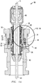
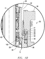
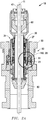
- Figure 1A and 1B depict a cross-section of an RCD 10 and an aligned piece of oilfield equipment 40 with a misalignment mitigation or correction device 50, not according to the present invention
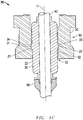
- Figure 1C depicts a cross-section of an RCD 10 and a misaligned piece of oilfield equipment 40 with a misalignment correction device 50, not according to the present invention.
- the RCD 10 has one or more sealing elements 80 for sealing an item of oilfield equipment 40 at a wellsite proximate a wellbore (or in a marine environment above and/or below the water; or for directional drilling under an obstacle) formed in the earth and lined with a casing.
- the one or more RCDs 10 may control pressure in the wellbore.
- an internal portion of the RCD 10 is designed to seal around a piece of oilfield equipment 40 and rotate with the oilfield equipment 40 by use of an internal sealing element 80, a latch assembly 30 and a rotating bearing assembly 20.
- the sealing elements 80 are shown and described herein as being located in an RCD 10 (rotational control device).
- the one or more sealing elements 80 may be one or more annular stripper rubbers, or sealing elements 80, located within the RCD 10.
- the sealing elements 80 may be configured to radially engage and seal the oilfield equipment 40 during oilfield operations.
- the internal portion of the RCD 10 and bearing assembly 20 permits the oilfield equipment 40 to move axially and slidably through the RCD 10.
- the oilfield equipment 40 may be any suitable equipment to be sealed by the sealing element 80 including, but not limited to, a drill string, a bushing, a bearing, a bearing assembly, a test plug, a snubbing adaptor, a docking sleeve, a sleeve, sealing elements, a tubular, a drill pipe, a tool joint, or even non-oilfield pieces of equipment such as for directional drilling under obstacles and the like.
- the misalignment correction device 50 in Figures 1A-C includes a spherical (rounded or arcuate) shoulder 21 machined onto the exterior surface 22 of bearing assembly 20 and a matching spherical (socket or arcuate) seat profile 31 machined onto the interior surface 32 of an annular piece 38, which is part of the latch assembly 30.
- Latch assembly 30 may further include a locking dog 33 which latches onto a matching profile 23 on bearing assembly 20 when in a locked position (as illustrated in Figures 1A and 1B ). The locking dog 33 retracts into the latch assembly 30 when in the unlocked position.
- locking dog profile 34 similarly to profile 31 of the annular piece 38, forms a mating complement to profile 23 of the spherical shoulder 21.
- the annular piece 38 may have a groove including a seal 35 to sealingly engage the spherical shoulder 21.
- the misalignment correction device 50 may also optionally include anti-rotational device(s) 190 to prevent unintentional rotation or spinning within the RCD 10.
- anti-rotational device 190 may be one or more keys 36 on the latch assembly 30 which extend into and engage one or more slots 29 on the bearing assembly 20.
- the keys 36 engaging the slots 29 may increase the robustness of the connection, inhibit rotation/spinning, and decrease friction and wear between the bearing assembly 20 and the latch assembly 30.
- the slots 29 may be uncovered/exposed or covered/enclosed. If enclosed, the slots 29 may completely cover the keys 36 in the assembled position thereby reducing the risk of damage to the keys 36 as the RCD 10 performs oilfield operations.
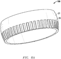
- FIG. 8A An exemplary embodiment of slots 29 of anti-rotational device 190, as defined on spherical shoulder 21, is depicted in Figure 8A . Accordingly, the slots 29 may be formed in the outer perimeter of the spherical shoulder 21 (optionally integral with the bearing assembly 20).
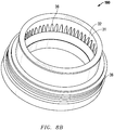
- Figure 8B depicts an exemplary embodiment of keys 36 formed on the interior surface 32 of the annular piece 38 of anti-rotational device 190. The keys 36 of Figure 8B may engage the slots 29 of Figure 8A .
- the keys 36 may be located proximate or even on the surface of the locking dog 33 and the slots 29 may be defined on the spherical shoulder 21. Alternatively or additionally, the keys 36 may be located elsewhere on the interior surface 32 of the annular piece 38 (e.g.
- the slots 29 may be defined in elsewhere on the exterior surface 22 of the bearing assembly 20.
- the slots may also appear on the annular piece 38 with the corresponding keys appearing on the spherical shoulder 21.
- the spherical shoulder 21 and matching profiles 31, 34 of misalignment correction device 50 allow for some rotation to compensate for some rotational or angular misalignment between the RCD 10, bearing assembly 20, latch assembly 30 and piece of oilfield equipment 40.
- the amount of rotational or angular misalignment that the misalignment correction device 50 is able to compensate for is limited by the clearance or distance defined by annular space 12 between the interior surface 32 of the annular piece 38 and the exterior surface 22 of the bearing assembly 20. Annular space 12 may be increased or decreased as desired for the particular oilfield operation at hand.
- the compensated misalignment increases the lifespan of seals 80 (see Fig. 1A ) and helps to avoid damage to bearing assemblies 20 and RCDs 10.
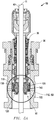
- Figures 2A and 2B depict a cross-section of an RCD 10 with an exemplary embodiment of a misalignment correction device 50 with a sleeve assembly 24.
- the bearing assembly 20 is coupled to a sleeve assembly 24 having a tube or sleeve 27 and a spherical shoulder 21.
- the sleeve assembly 24 may be coupled to the bearing assembly 20 through bolts, screws, pins, or any other suitable means.
- the sleeve assembly 24 may have an annular cavity 25 between the spherical shoulder 21 and the bearing assembly 20. Further, the exemplary embodiment may include one or more thrust bearings 26 at an interface where the tube or sleeve 27 is connected to the spherical shoulder 21.
- the latch assembly 30 in Figures 2A-B has a matching seat profile 31 machined onto the interior surface 32 of the annular piece 38.
- the latch assembly 30 also includes a locking dog 33 which latches onto a matching profile 23 on the bearing assembly 20 when in a locked position (as illustrated in Figures 2A-B ).
- locking dog profile 34 similar to profile 31 of annular piece 38, forms a mating complement to profile 23 of the spherical shoulder 21.
- the misalignment correction device 50 exemplary embodiment may also have one or more anti-rotational devices 190 to inhibit unintended rotation or spinning, such as the exemplary embodiment of an anti-rotational device 190 as depicted in Figure 8A and 8B and described above.
- the latch assembly 30 may include a seal 35 to sealingly engage the spherical shoulder 21.
- the spherical shoulder 21 and matching profiles 31, 34 of misalignment correction device 50 allow for some rotation to compensate for rotational or angular misalignment between the RCD 10, bearing assembly 20, latch assembly 30 and piece of oilfield equipment 40.
- the exemplary embodiment depicted in Figures 2A-B further compensates for horizontal misalignment between the RCD 10, bearing assembly 20, latch assembly 30 and piece of oilfield equipment 40.
- Movable plates (not illustrated in Figures 2A-B but see Fig. 4C and accompanying discussion) on the thrust bearings 26 installed between the spherical shoulder 21 and tube or sleeve 27 enable the misalignment correction device 50 to shift laterally or radially away from axis 11 to compensate for horizontal misalignment.
- annular space 25 limits the amount of rotational or angular misalignment that the misalignment device 50 is able to compensate for. Further, the sizes of annular space 12 and annular cavity 25 may be adjusted as desired to meet the needs of the oilfield operation at hand.
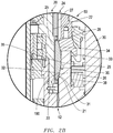
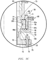
- Figures 3A-C depict a cross-section of an RCD 10 with an alternate exemplary embodiment of a misalignment correction device 50 with a carrier 60 and floating joint 70.
- Carrier 60 is in the form of a housing 62 which support one or more plates 61 and floating joint 70. Further, the housing 62 has an interior wall 66.
- the carrier 60 may be located below the bearing assembly 20 in the exemplary embodiment illustrated in Figures 3A-C , but in other exemplary embodiments the carrier 60 may be located above or within the bearing assembly 20.
- the plates 61 are constructed of a nonflexible material such as steel, and have an inner surface 64 and an outer surface 65. While plates 61 are illustrated as an upper plate 61a and a lower plate 61b, any number of plates 61 may be contained in the housing 62.
- the inner surface 64 of the plates 61 has a socket shape profile 200, and surrounds and engages with the floating joint 70.
- the outer surface 65 of plates 61 may also define one or more slots 69, to which one or more keys 37, as defined on latch assembly 30, engage.
- the plates 61 further, may include seals 63 to form fluid tight seals between the top and bottom surfaces of plates 61 that are adjacent to the housing 62 and the inner surface 64 adjacent to the spherical shoulder 71.
- the outer surface 65 of the plate(s) 61 does not fully sit flush against the interior wall 66 of housing 62. Instead, the outer surface 65 of the plates 61 forms a chamber 67 with interior wall 66 of housing 62 inside carrier 60.
- the floating joint 70 may be constructed of multiple parts, such as an upper piece 74 and a lower piece 75 which are connected or joined together, as illustrated in Figures 3A-C . However, it should be appreciated that the floating joint 70 may also be a singular, unitary piece, or any number of pieces, so long as the features described for both the upper piece 74 and lower piece 75 are present.
- the floating joint 70 has an exterior surface 72 defining a rounded, spherical shoulder 71, here depicted on the upper piece 74.
- the upper piece 74 and lower piece 75 together define an inner surface 76 of the floating joint 70.
- the inner surface 76 establishes a cylindrical space through which the piece of oilfield equipment 40 may travel therethrough.
- This exemplary embodiment may include anti-rotational device(s) 190.
- the exterior surface 72 of the floating joint 70 may also have one or more slots 79 (e.g. defined in the face of spherical shoulder 71) which are engaged by one or more keys 68 on the plates 61 (and/or, the keys 68 may be respectively located above and below the plates 61a and 61b and engage slots respectively in the top of plate 61a and in the bottom of plate 61b). Keys 68 may be jutted or have two levels for a more secure fit in a mating cavity/slot 79.
- One exemplary embodiment of the anti-rotational device 190 may be similar to that as reflected in Figures 8A and 8B as described above.
- the lower piece 75 may be connected to the upper piece 74 through means including, but not limited to: bolts, pins, screws or any other suitable means. Further, the lower piece 75 may have a flange 77 to which sealing element 80 is mounted, bonded or bolted to below the floating joint 70. It is to be appreciated that, while the floating joint 70 and carrier 60 is illustrated in Figures 3A-C as being below the bearing assembly 20, and above the sealing element 80, the floating joint 70, carrier 60 and sealing element 80 may be located above or within the bearing assembly 20 as well. Any floating joint described herein may also incorporate an expandable bladder-type clutch as an anti-rotational device(s) 190 such as described in US Patent No. 6,725,938 .
- the spherical shoulder 71 engages with and is supported by the inner surface 64 of the plates 61.
- the interior wall 66a of housing 62 does not contact the floating joint 70 while there is no misalignment.
- the interior wall 66a is arranged such that there is an annular space 73 between the interior wall 66a of the housing 62 and the exterior surface 72 of the floating joint 70. This annular space 73 may be increased or decreased as desired for the needs of the particular oilfield operation and exists both above and below the spherical shoulder 71.
- the spherical shoulder 71 and inner surface 64 of plates 61 allow for some rotation to compensate for some rotational or angular misalignment between the RCD 10, bearing assembly 20, latch assembly 30 and piece of oilfield equipment 40.
- the exemplary embodiment depicted in Figures 3A-C also compensates for horizontal misalignment between the RCD 10, bearing assembly 20, latch assembly 30 and piece of oilfield equipment 40 through the chamber 67 and annular space 73.
- the chamber 67 allows the plates 61 to move horizontally across axis 11 to compensate for horizontal misalignment; and annular space 73 also functions similarly to allow floating joint 70 to move, shift or float horizontally across axis 11 to compensate for horizontal misalignment as well.
- the keys 37, 68 engaging the slots 69, 79 may increase the robustness of the connection, inhibit rotation/spinning, and decrease friction and wear between the latch assembly 30, the floating joint 70, and the plates 61.
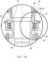
- the exemplary embodiment of the misalignment correction device 50 shown in Figures 3A-C may optionally further include one or more thrust bearings 90 (depicted in Figures 4A-C ).
- thrust bearings 90 depictted in Figures 4A-C .
- FIG. 4A-C there are two thrust bearings 90 in the exemplary embodiment of Figures 4A-C : one thrust bearing 90a installed between the upper plate 61a and the housing interior wall 66, and one thrust bearing 90b installed between the lower plate 61b and the housing interior wall 66; however, it should be appreciated that any number of thrust bearings 90 may be installed between the plates 61 and the housing 62. In alternate exemplary embodiments, the thrust bearings 90 may be installed elsewhere on or within the RCD 10.
- Each of the thrust bearings 90 incorporates a fixed ring 91, a sliding or movable ring 93 and bearings 92 between the rings 91 and 93.
- the fixed ring 91 is attached or mounted to the housing 62.
- the sliding or movable ring 93 is attached to the plates 61, and may slide radially or horizontally into and out of chamber 67 in response to plates 61 shifting towards or away from the axis 11.
- the bearings 92 sit in between the rings 91, 93 and may be any suitable type of rolling type bearings including but not limited to: balls, cylindrical rollers, spherical rollers, tapered rollers, and needle rollers.
- the thrust bearings 90 enable the plates 61 to more easily slide or shift in compensating for any horizontal misalignment and also help to minimize damage to the RCD 10, bearing assembly 20, latch assembly 30 and piece of oilfield equipment 40.
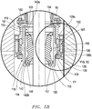
- Figures 5A-C depict a cross-section of an RCD 10 with an alternate exemplary embodiment of a misalignment correction device 50 with a carrier 100, floating joint 110, and pressure reduction system 120.
- the exemplary embodiment of the misalignment correction device 50 in Figures 5A-C may be located above, below or within the bearing assembly 20 of RCD 10.
- the carrier 100 has a cylindrical wall 101 surrounding a chamber 103 within to allow for the retention and support of the floating joint 110, sealing element 140 and a piece of oilfield equipment 40. Further, the carrier 100 may have an end cap or collar 102 through which the carrier 100 may be attached or mounted to the bearing assembly 20.
- the cylindrical wall 101 of carrier 100 is constructed to retain the plates 105, the pressure reduction system 120 and an optional nitrogen accumulator 130.
- the plates 105 may include any number of plates, but in Figures 5A-C are shown as an upper plate 105a and a lower plate 105b. Plates 105 may have an inner surface 107 and an outer surface 108. The inner surface 107 of plates 105 are machined into a socket shape profile 200 to engage the spherical shoulder 111 of the floating joint 110. The outer surface 108 may also define one or more slots 163 into which keys 162, as defined on the carrier wall 104, may engage. Optionally, as anti-rotational device(s) 190, the inner surface 107 may also define one or more keys 160, which extend into and engage with slots 161 as defined on the spherical shoulder 111.
- a port 106 is defined between the upper plate 105a and lower plate 105b, and is configured to allow the flow of a fluid to pass therethrough to the pressure reduction system 120.
- the plates 105 further, may include seals 109 to sealingly engage the top and bottom surfaces of plates 105 that are adjacent to the carrier 100 and the inner surface 107 adjacent to the spherical shoulder 111 of floating joint 110.
- the floating joint 110 may be constructed of multiple parts, such as an upper piece 112 and a lower piece 113. However, it should be appreciated that the floating joint 110 may also be a singular, unitary piece, or any number of pieces, so long as the features described for both the upper piece 112 and lower piece 113 are present.
- the floating joint 110 has an exterior surface 114 defining a rounded, spherical shoulder 111.
- the upper piece 112 and lower piece 113 together define an inner surface 115 of the floating joint 110 as well as a port 116 between the two pieces 112, 113.
- the port 116 is configured to allow the flow of a fluid to pass therethrough to the pressure reduction system 120.
- the inner surface 115 of floating joint 110 establishes a cylindrical space, and part of chamber 103, through which the piece of oilfield equipment 40 may travel therethrough.
- the inner surface 115 and the outer diameter 146 of sealing element 140 may define a sealed chamber 145, in which a volume of fluid 147, such as an oil, may be contained.
- the one or more plurality of ports 116, 106, and 128 enable the wellbore pressure to influence the outer diameter 146 of sealing element 140.
- the floating joint 110 may also have an end cap or collar 117 to which sealing element 140 may be mounted, bonded or bolted to.
- the spherical shoulder 111 engages with and is supported by the inner surface 107 of the plates 105.
- the interior wall 104 of the carrier 100 does not make physical contact with the floating joint 110 while there is no misalignment.
- the interior wall 104 is arranged such that there is an annular space 118 between the interior wall 104 of the carrier 100 and the exterior surface 114 of the floating joint 110.
- the annular space 118 exists both above and below the spherical shoulder 111. This annular space 118 may be increased or decreased as desired for the needs of the particular oilfield operation.
- the sealing element 140 is mounted, attached or bonded to a top ring 142a and a bottom ring 142b. While the sealing element 140 may be formed from a solid flexible material, such as an elastomer or rubber, the rings 142 may be formed from rigid or stiffer materials than the flexible material used for sealing element 140, such as a metal. Top ring 142a and bottom ring 142b may have fluid-tight seals 143 adjacent to the floating joint 110. Further, sealing element 140 may have an inner diameter 144, which seals against the piece of oilfield equipment 40, and an outer diameter 146. Sealing element 140, carrier 100 and floating joint 110 together delineate the chamber 103 through which a piece of oilfield equipment 40 may travel therethrough.
- the bottom ring 142b of sealing element 140 is in a fixed position relative to the floating joint 110.
- the bottom ring 142b is fixed to floating joint 110 through attaching or mounting to the floating joint 110 using conventional means such as screws, pins or bolts 148 or bonding.
- the top ring 142a may float or shift uphole and downhole in response to the piece of oilfield equipment 40 being stripped in or out of the RCD 10.
- the top ring 142a may be in a fixed position relative to floating joint 110 and the bottom ring 142b may float; both rings 142a, 142b may float; or both rings 142a, 142b may be fixed.
- Pressure reduction system 120 Adjacent to the plates 105, and also housed within the cylindrical wall 101, is the pressure reduction system 120, and optionally, a nitrogen accumulator 130.
- Pressure reduction system 120 is in communication with the wellbore and supplies fluid to the RCD 10.
- the pressure reduction system 120 typically includes a piston assembly 129, an upper chamber 126 and a lower chamber 127.
- the piston assembly 129 includes a smaller piston 121 and a larger piston 123.
- the smaller piston 121 has a relatively smaller surface area 122 as compared to the larger piston 123 which has a relatively larger surface area 124.
- the pressure in upper chamber 126 and chamber 145 is labeled as P1.
- the pressure in the lower chamber 127, as well as the pressure of the wellbore (or other system pressure) is labeled as P2.
- the pistons 121 and 123 are constructed and arranged to maintain a pressure differential between the P1 and P2.
- the pistons 121 and 123 are designed with a specific surface area ratio between surface areas 122 and 124 to maintain about a pressure differential, for example, of 1000 psi (or 6894.75 kPa), between the chambers 145, 126 and the wellbore pressure (in other words, between P1 and P2) thereby allowing the P1 to be 1000 psi lower than P2.
- a plurality of seal members 125 may be disposed around the pistons 121 and 123 to form a fluid tight seal between the chambers 126 and 127.
- the pressure reduction system 120 is also in fluid communication with a compensator such as a nitrogen accumulator 130.
- the nitrogen accumulator 130 may include a nitrogen chamber 132 and a nitrogen piston 134. Additionally, one or more seal members 125 may be disposed around the nitrogen piston 134 to form a fluid tight seal between the chambers 126 and 132. If P1 in chambers 145, 126 fluctuates, as when filling the chamber 126 with oil and/or when the sealing element 140 deforms, the nitrogen piston 134 may adjust into or out of nitrogen chamber 132 to allow for a margin of error to maintain a seal around the piece of oilfield equipment 40.
- Nitrogen chamber 132 may be filled with a pressure controlled volume of gas 138, such as a nitrogen gas, as would be known to one having ordinary skill in the art.
- a pressure transducer (not shown) measures the wellbore pressure P2 and subsequently injects nitrogen into the chamber 132 at the same pressure as pressure P2.
- the pressure in the nitrogen chamber 132 may be adjusted as the wellbore pressure P2 changes, thereby maintaining the desired pressure differential, for example, of 6895 kPa (1000 psi), between pressure P1 and well bore pressure P2.
- the pressure reduction system 120 provides reduced pressure from the wellbore to activate the sealing element 140 to seal around the piece of oilfield equipment 40.
- a volume of fluid 147 such as oil
- the wellbore fluid from the wellbore is in fluid communication with lower chamber 127 through port 128 in the carrier 100. Therefore, as the wellbore pressure increases, pressure P2 in the lower chamber 127 increases.
- the pressure in the lower chamber 127 causes the pistons 121 and 123 to move axially upward forcing fluid in the upper chamber 126 to enter ports 136, 106, 116 and pressurize the chamber 145.
- the pressure P1 in the chamber 145 and upper chamber 126 increases causing the sealing element 140 to move radially inward to seal around the piece of oilfield equipment 40.
- the sealing element 140 is indirectly activated by the well bore pressure, allowing the RCD 10 to seal around a piece of oilfield equipment 40.
- the pressure reduction system 120 acts to reduce pressure P2 to a reduced pressure P1 in the chambers 145 and 126, the sealing element 140 experiences a reduced pressure load for closing against oilfield equipment 40.
- a sealing element 140 may be rated for 2500 psi wellbore pressure P2, the sealing element may only need to carry 1500psi closing pressure P1.
- the reduced pressure on the sealing element 140 extends the usable lifetime of the sealing element 140.
- the spherical shoulder 111 and matching inner surface 107 of the plates 105 allow for some rotation to compensate for rotational or angular misalignment between the RCD 10, bearing assembly 20, latch assembly 30 and piece of oilfield equipment 40.
- the amount of rotational or angular misalignment that the misalignment correction device 50 is able to compensate for is limited by the clearance or distance defined by annular space 118 between the interior wall 104 of the carrier 100 and the exterior surface 114 of the floating joint 110.
- Annular space 118 may be increased or decreased as desired for the certain oilfield operation at hand.
- the compensated misalignment increases the lifespan of sealing element 140 and helps to avoid damage to bearing assemblies 20 and RCDs 10.
- the keys 160, 162 engaging the slots 161, 163 may increase the robustness of the connection, inhibit rotation/spinning, and decrease friction and wear between the piece of the floating joint 110, carrier 100, and the plates 105.
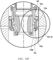
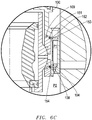
- the exemplary embodiment of the misalignment correction device 50 shown in Figures 5A-C may optionally further include one or more thrust bearings 150 (depicted in Figures 6A-C ).
- thrust bearings 150 depictted in Figures 6A-C .
- components in Figures 6A-C that are similar to components in prior figures will be labeled with the same number indicator.
- the outer surface 108 of the plates 105 does not fully sit flush against the interior wall 104 of the carrier 100. Instead, the outer surface 108 of the plates 105 forms a chamber 154 with interior wall 104 of the carrier 100.
- Each of the thrust bearings 150 incorporates a fixed ring 151, a sliding or movable ring 153 and bearings 152 between the rings 151 and 153.
- the fixed ring 151 is attached or mounted to the carrier 100.
- the sliding or movable ring 153 is attached to the plates 105, and may slide radially or horizontally into and out of chamber 154 in response to plates 105 shifting towards or away from the axis 11.
- the bearings 152 sit in between the rings 151, 153 and may be any suitable type of rolling type bearings including but not limited to: balls, cylindrical rollers, spherical rollers, tapered rollers, and needle rollers.
- the thrust bearings 150 enable the plates 105 to more easily slide or shift in compensating for any horizontal misalignment and also help to minimize damage to the RCD 10, bearing assembly 20, latch assembly 30 and piece of oilfield equipment 40.
- Figure 7 depicts a cross-section of an RCD 10 with an alternate exemplary embodiment of a misalignment correction device 50 with a floating joint 180 and spool 170.
- the spool 170 is mounted below the RCD 10, but in another exemplary embodiment, may be elsewhere (such as above) the RCD 10, and alternatively, may be mounted proximate but not necessarily abutting the RCD 10.
- the spool 170 has an interior wall 171 defining a chamber 172 within which one or more plates 173 are housed.
- the exemplary embodiment may optionally include one or more thrust bearings 174 at the interface where the plates 173 lie adjacent to the interior wall 171.
- the outer surface 176 of the plates 173 do not sit fully flush against the interior wall 171a.
- the inner surface 175 of the plates 173 are machined into a socket shape profile 200 to engage the spherical shoulder 181 of floating joint 180.
- the plates 173, further, may include seals 178 to sealingly engage the top and bottom surfaces of plates 173 that are adjacent to the spool 170 and the inner surface 115 adjacent to the spherical shoulder 181 of floating joint 180.
- the floating joint 180 has an exterior surface 182 defining a rounded, spherical shoulder 181.
- the inner surface 183 of floating joint 180 establishes a cylindrical space through which the piece of oilfield equipment 40 may travel therethrough.
- the spherical shoulder 181 engages with and is supported by the inner surface 175 of the plates 173.
- the interior wall 171 of the spool 170 does not contact the floating joint 180 while there is no misalignment.
- the interior wall 171 is arranged such that there is an annular space 186 between the interior wall 171 of the spool 170 and the exterior surface 182 of the floating joint 180. This annular space 186 may be increased or decreased as desired for the needs of the particular oilfield operation, and may exist above and below the spherical shoulder 181.
- anti-rotational devices 190 such as or similar to the exemplary embodiment of anti-rotational device 190 depicted in Figures 8A-8B as described above, may be included between the floating joint 180 and the plates 173, and/or between the plates 173 and the spool 170.
- the exemplary embodiment depicted in Figure 7 allows some rotation and radial movement to compensate for some rotational and horizontal misalignment between the RCD 10, latch assembly 30, bearing assembly 20 (not shown in Figure 7 ), spool 170, and piece of oilfield equipment 40.
- Thrust bearings 174 may also be installed to help alleviate horizontal misalignment present in RCD 10 beyond the limits of the annular space 186 and chamber 172.
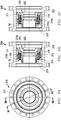
- Figure 9A depicts an end view of an RCD receiver/fitting 210 with an exemplary embodiment of a misalignment mitigation or correction device 50 for locating and/or placing internal oilfield equipment such as a bearing assembly (not shown).
- Figure 9B is a cross-section of Figure 9A , taken along line 9B-9B and
- Figure 9C is a cross-section of Figure 9A , taken along line 9C-9C.
- the RCD receiver 210 includes a floating joint 215 having a spherical shoulder 211.
- a corresponding surface in the shape of a socket shape profile 200 is defined by an annular piece 216.
- the annular piece 216 may be comprised of two ring-like pieces, a primary annular piece 216a and a secondary annular piece 216b, of which the secondary annular piece 216b may be relatively smaller in size as compared to the primary annular piece 216a.
- the inner surface of the two pieces 216a and 216b together may form the socket shape profile 200.
- the exemplary embodiment of the RCD receiver 210 may include an anti-rotational device 190.
- the exemplary embodiment of the RCD receiver 210 may include a locking dog 212 and a profile 214. In addition to a locking functionality, the locking dog 212 and profile 214 together may also have the functionality of an anti-rotational device 190.
- An inner annular member 220 may include an inward latching mechanism 222 (or profile).
- the exemplary embodiment as depicted in Figures 9A-C may be utilized to minimize misalignment when the operator requires the location and/or retrieval of internal oilfield equipment. Further, the anti-rotational devices 190 may reduce and/or inhibit unintentional rotation or spinning within the RCD receiver 210 or relative internals as the internal oilfield equipment is located.
Landscapes
- Engineering & Computer Science (AREA)
- Geology (AREA)
- Life Sciences & Earth Sciences (AREA)
- Mining & Mineral Resources (AREA)
- Physics & Mathematics (AREA)
- Environmental & Geological Engineering (AREA)
- Fluid Mechanics (AREA)
- General Life Sciences & Earth Sciences (AREA)
- Geochemistry & Mineralogy (AREA)
- Mechanical Engineering (AREA)
- Earth Drilling (AREA)
- Orthopedics, Nursing, And Contraception (AREA)
- Percussion Or Vibration Massage (AREA)
Claims (12)
- System zur Verwendung in einem Bohrloch, wobei das System eine drehende Kontrollvorrichtung und eine Fehlausrichtungskorrekturvorrichtung (50) zum Abschwächen einer Winkel-Fehlausrichtung zwischen der drehenden Kontrollvorrichtung und einem Teil einer Ölfeld-Ausrüstung (40) in der drehenden Kontrollvorrichtung (10) umfasst, wobei die Fehlausrichtungskorrekturvorrichtung Folgendes umfasst:einen abgerundeten Absatz (71) an einer ersten Fläche (72) innerhalb der drehenden Kontrollvorrichtung (10) undein Fassungsprofil (200) an einer zweiten Fläche (64) innerhalb der drehenden Kontrollvorrichtung (10), wobei die zweite Fläche (32) konfiguriert ist, um an den abgerundeten Absatz (71) anzustoßen, und ferner wobei der abgerundete Absatz (71) konfiguriert ist, um sich innerhalb des Fassungsprofils (200) um eine Achse, senkrecht zu einer Längsachse (11) der drehenden Kontrollvorrichtung (10), zu drehen, um eine Fehlausrichtung zwischen der drehenden Kontrollvorrichtung (10) und dem Teil einer Ölfeld-Ausrüstung (40) auszugleichen,wobei das System dadurch gekennzeichnet ist, dassdie Fehlausrichtungskorrekturvorrichtung ferner ein schwimmendes Gelenk (70) umfasst, das eine Außenfläche (72) innerhalb der drehenden Kontrollvorrichtung (10) aufweist, wobei das schwimmende Gelenk (70) konfiguriert ist, um sich in Radialrichtung zu verschieben, um eine horizontale Fehlausrichtung zwischen der drehenden Kontrollvorrichtung (10) und dem Teil einer Ölfeld-Ausrüstung (40) auszugleichen.
- System nach Anspruch 1, wobei die drehende Kontrollvorrichtung (10) ferner eine Lagerbaugruppe (20), einen Abdichtungselementträger oder eine Aufnahme mit einer Außenfläche innerhalb der drehenden Kontrollvorrichtung (10) umfasst, wobei die erste Fläche (72) auf der Außenfläche der/des jeweiligen Lagerbaugruppe (20), Abdichtungselementträgers oder Aufnahme definiert ist.
- System nach Anspruch 2, wobei die drehende Kontrollvorrichtung (10) ferner eine Klinkenbaugruppe (30) umfasst, die ein ringförmiges Teil (38) aufweist, das eine Innenfläche definiert, welche die Lagerbaugruppe (20) umgibt, wobei das Fassungsprofil (200) auf der Innenfläche des ringförmigen Teils (38) definiert ist.
- System nach Anspruch 1, wobei die Fehlausrichtungskorrekturvorrichtung einen oberen Ring (142a) umfasst, der konfiguriert ist, um sich lochaufwärts und lochabwärts innerhalb der drehenden Kontrollvorrichtung (10) zu verschieben.
- System nach Anspruch 1, wobei die Fehlausrichtungskorrekturvorrichtung ferner eine oder mehrere Platten (61) umfasst, die eine Innenfläche innerhalb der drehenden Kontrollvorrichtung (10) aufweisen, wobei das Fassungsprofil (200) auf der Innenfläche der einen oder mehreren Platten (61) definiert ist.
- System nach Anspruch 1, das ferner Folgendes umfasst:eine Lagerbaugruppe (20) innerhalb der drehenden Kontrollvorrichtung (10) undeine Hülse (27), die eine Innenfläche und eine Außenfläche aufweist, wobei die Innenfläche mit der Lagerbaugruppe (20) verbunden ist und ferner wobei die erste Fläche (72) auf der Außenfläche der Hülse (27) definiert ist.
- System nach Anspruch 1, das ferner ein oder mehrere Drucklager (26) innerhalb der drehenden Kontrollvorrichtung (10) umfasst.
- System nach Anspruch 1, das ferner Folgendes umfasst:einen oder mehrere Schlitze (69), die auf der ersten Fläche (22) definiert sind, undeinen oder mehrere Passfedern (37), die auf der zweiten Fläche (32) definiert sind, wobei die Passfedern (37) konfiguriert sind, um die Schlitze (69) in Eingriff zu nehmen, und ferner konfiguriert sind, um eine relative Drehung zwischen der ersten Fläche (22) und der zweiten Fläche (32) um die Längsachse (11) zu verhindern.
- Verfahren zum Abschwächen einer Fehlausrichtung zwischen einer drehenden Kontrollvorrichtung und einem Teil einer Ölfeld-Ausrüstung (40) innerhalb der drehenden Kontrollvorrichtung (10), wobei das Verfahren die folgenden Schritte umfasst:
Unterbringen des Teils einer Ölfeld-Ausrüstung (40) innerhalb einer Fehlausrichtungskorrekturvorrichtung (50) innerhalb der drehenden Kontrollvorrichtung und nahe einer Lagerbaugruppe (20) der drehenden Kontrollvorrichtung, wobei die Fehlausrichtungskorrekturvorrichtung Folgendes umfasst:einen abgerundeten Absatz (71) an einer ersten Fläche (72) der drehenden Kontrollvorrichtung innerhalb der drehenden Kontrollvorrichtung (10),ein Fassungsprofil (200) an einer zweiten Fläche (64) der drehenden Kontrollvorrichtung innerhalb der drehenden Kontrollvorrichtung (10), wobei die zweite Fläche (64) konfiguriert ist, um an den abgerundeten Absatz (71) anzustoßen, und ferner wobei der abgerundete Absatz (71) konfiguriert ist, um sich innerhalb des Fassungsprofils (200) um eine Achse, senkrecht zu einer Längsachse (11) der drehenden Kontrollvorrichtung (10), zu drehen, um eine Winkel-Fehlausrichtung zwischen der drehenden Kontrollvorrichtung (10) und dem Teil einer Ölfeld-Ausrüstung (40) auszugleichen, undein schwimmendes Gelenk (70), das eine Außenfläche (72) innerhalb der drehenden Kontrollvorrichtung (10) aufweist, wobei das schwimmende Gelenk (70) konfiguriert ist, um sich in Radialrichtung zu verschieben, um eine horizontale Fehlausrichtung zwischen der drehenden Kontrollvorrichtung (10) und dem Teil einer Ölfeld-Ausrüstung (40) auszugleichen, undKorrigieren einer Fehlausrichtung durch:(a) Drehen des abgerundeten Absatzes (21) um die Achse, senkrecht zu der Längsachse (11) der drehenden Kontrollvorrichtung (10), in Reaktion auf die Winkel-Fehlausrichtung zwischen der drehenden Kontrollvorrichtung (10) und dem Teil einer Ölfeld-Ausrüstung (40) undBegrenzen der Drehung des abgerundeten Absatzes (71) oder
(b) Verschieben des schwimmenden Gelenks (70) in Radialrichtung in Reaktion auf die horizontale Fehlausrichtung zwischen der drehenden Kontrollvorrichtung (10) und dem Teil einer Ölfeld-Ausrüstung (40) undBegrenzen der radialen Verschiebung des schwimmenden Gelenks (70). - Verfahren nach Anspruch 9, das ferner den folgenden Schritt umfasst:
Verschieben eines oberen Rings (142a) lochaufwärts und lochabwärts in Reaktion auf eine Bewegung des Teils einer Ölfeld-Ausrüstung (40). - Verfahren nach Anspruch 9, wobei der Schritt des Verschiebens des schwimmenden Gelenks (70) ferner den folgenden Schritt umfasst:
seitliches Verschieben einer Platte (61) in eine Kammer (67). - Verfahren nach Anspruch 9, das ferner den folgenden Schritt umfasst:
Verhindern, dass sich der abgerundete Absatz (71) um die Längsachse (11) des Teils einer Ölfeld-Ausrüstung (40) dreht.
Priority Applications (2)
| Application Number | Priority Date | Filing Date | Title |
|---|---|---|---|
| EP17196403.4A EP3290633B1 (de) | 2014-05-29 | 2015-05-29 | Fehlausrichtungsverringerung in einer rotierenden steuerungsvorrichtung |
| EP20210805.6A EP3805519B1 (de) | 2014-05-29 | 2015-05-29 | Fehlausrichtungsverringerung in einer rotierenden steuerungsvorrichtung |
Applications Claiming Priority (2)
| Application Number | Priority Date | Filing Date | Title |
|---|---|---|---|
| US201462004624P | 2014-05-29 | 2014-05-29 | |
| PCT/US2015/033209 WO2015184275A1 (en) | 2014-05-29 | 2015-05-29 | Misalignment mitigation in a rotating control device |
Related Child Applications (3)
| Application Number | Title | Priority Date | Filing Date |
|---|---|---|---|
| EP17196403.4A Division-Into EP3290633B1 (de) | 2014-05-29 | 2015-05-29 | Fehlausrichtungsverringerung in einer rotierenden steuerungsvorrichtung |
| EP17196403.4A Division EP3290633B1 (de) | 2014-05-29 | 2015-05-29 | Fehlausrichtungsverringerung in einer rotierenden steuerungsvorrichtung |
| EP20210805.6A Division EP3805519B1 (de) | 2014-05-29 | 2015-05-29 | Fehlausrichtungsverringerung in einer rotierenden steuerungsvorrichtung |
Publications (2)
| Publication Number | Publication Date |
|---|---|
| EP3149268A1 EP3149268A1 (de) | 2017-04-05 |
| EP3149268B1 true EP3149268B1 (de) | 2020-12-02 |
Family
ID=53284686
Family Applications (3)
| Application Number | Title | Priority Date | Filing Date |
|---|---|---|---|
| EP17196403.4A Not-in-force EP3290633B1 (de) | 2014-05-29 | 2015-05-29 | Fehlausrichtungsverringerung in einer rotierenden steuerungsvorrichtung |
| EP15727285.7A Active EP3149268B1 (de) | 2014-05-29 | 2015-05-29 | Milderung der fehlausrichtung in einem rotierenden kontrolgerät |
| EP20210805.6A Active EP3805519B1 (de) | 2014-05-29 | 2015-05-29 | Fehlausrichtungsverringerung in einer rotierenden steuerungsvorrichtung |
Family Applications Before (1)
| Application Number | Title | Priority Date | Filing Date |
|---|---|---|---|
| EP17196403.4A Not-in-force EP3290633B1 (de) | 2014-05-29 | 2015-05-29 | Fehlausrichtungsverringerung in einer rotierenden steuerungsvorrichtung |
Family Applications After (1)
| Application Number | Title | Priority Date | Filing Date |
|---|---|---|---|
| EP20210805.6A Active EP3805519B1 (de) | 2014-05-29 | 2015-05-29 | Fehlausrichtungsverringerung in einer rotierenden steuerungsvorrichtung |
Country Status (9)
| Country | Link |
|---|---|
| US (1) | US9932786B2 (de) |
| EP (3) | EP3290633B1 (de) |
| AU (1) | AU2015266783C1 (de) |
| BR (1) | BR112016025078A2 (de) |
| CA (1) | CA2946005C (de) |
| EA (1) | EA201692141A1 (de) |
| MX (2) | MX2016014194A (de) |
| SG (1) | SG11201609034RA (de) |
| WO (1) | WO2015184275A1 (de) |
Families Citing this family (6)
| Publication number | Priority date | Publication date | Assignee | Title |
|---|---|---|---|---|
| WO2015184275A1 (en) * | 2014-05-29 | 2015-12-03 | Weatherford Technology Holdings, Llc | Misalignment mitigation in a rotating control device |
| US11473377B2 (en) | 2019-04-12 | 2022-10-18 | NTDrill Holdings, LLC | Rotating control device with flexible sleeve |
| EP4248056A4 (de) * | 2020-11-19 | 2024-10-23 | Opla Energy Ltd. | Drehsteuerungsvorrichtung |
| US12110757B2 (en) | 2020-11-21 | 2024-10-08 | Electrical Subsea & Drilling As | Packer arrangement for sealingly guiding a drillstring therethrough |
| NO347017B1 (no) * | 2020-11-21 | 2023-04-11 | Electrical Subsea & Drilling As | Pakningsarrangement for tettende gjennomføring av en borestreng |
| WO2025097233A1 (en) * | 2023-11-10 | 2025-05-15 | Beyond Energy Services And Technology Corp. | Rotating control device retaining mechanism |
Family Cites Families (15)
| Publication number | Priority date | Publication date | Assignee | Title |
|---|---|---|---|---|
| US5647444A (en) * | 1992-09-18 | 1997-07-15 | Williams; John R. | Rotating blowout preventor |
| US5662181A (en) | 1992-09-30 | 1997-09-02 | Williams; John R. | Rotating blowout preventer |
| US6138774A (en) | 1998-03-02 | 2000-10-31 | Weatherford Holding U.S., Inc. | Method and apparatus for drilling a borehole into a subsea abnormal pore pressure environment |
| US6263982B1 (en) | 1998-03-02 | 2001-07-24 | Weatherford Holding U.S., Inc. | Method and system for return of drilling fluid from a sealed marine riser to a floating drilling rig while drilling |
| GB2345074A (en) | 1998-12-24 | 2000-06-28 | Weatherford Lamb | Floating joint to facilitate the connection of tubulars using a top drive |
| US7159669B2 (en) | 1999-03-02 | 2007-01-09 | Weatherford/Lamb, Inc. | Internal riser rotating control head |
| US7926593B2 (en) | 2004-11-23 | 2011-04-19 | Weatherford/Lamb, Inc. | Rotating control device docking station |
| US8286734B2 (en) * | 2007-10-23 | 2012-10-16 | Weatherford/Lamb, Inc. | Low profile rotating control device |
| US8844652B2 (en) * | 2007-10-23 | 2014-09-30 | Weatherford/Lamb, Inc. | Interlocking low profile rotating control device |
| US8347983B2 (en) * | 2009-07-31 | 2013-01-08 | Weatherford/Lamb, Inc. | Drilling with a high pressure rotating control device |
| US9010433B2 (en) * | 2010-07-16 | 2015-04-21 | Weatherford Technology Holdings, Llc | Positive retraction latch locking dog for a rotating control device |
| GB2501489A (en) * | 2012-04-24 | 2013-10-30 | First Subsea Ltd | Rotatable joint for receiving a tubular |
| EP2864580A2 (de) * | 2012-06-25 | 2015-04-29 | Weatherford Technology Holdings, LLC | Führung für ein dichtungselement |
| GB2524790B (en) * | 2014-04-02 | 2018-02-07 | Schlumberger Holdings | Aligning borehole drilling equipment |
| WO2015184275A1 (en) * | 2014-05-29 | 2015-12-03 | Weatherford Technology Holdings, Llc | Misalignment mitigation in a rotating control device |
-
2015
- 2015-05-29 WO PCT/US2015/033209 patent/WO2015184275A1/en not_active Ceased
- 2015-05-29 EP EP17196403.4A patent/EP3290633B1/de not_active Not-in-force
- 2015-05-29 EA EA201692141A patent/EA201692141A1/ru unknown
- 2015-05-29 MX MX2016014194A patent/MX2016014194A/es unknown
- 2015-05-29 SG SG11201609034RA patent/SG11201609034RA/en unknown
- 2015-05-29 BR BR112016025078-8A patent/BR112016025078A2/pt active Search and Examination
- 2015-05-29 EP EP15727285.7A patent/EP3149268B1/de active Active
- 2015-05-29 CA CA2946005A patent/CA2946005C/en not_active Expired - Fee Related
- 2015-05-29 US US14/725,291 patent/US9932786B2/en active Active
- 2015-05-29 EP EP20210805.6A patent/EP3805519B1/de active Active
- 2015-05-29 AU AU2015266783A patent/AU2015266783C1/en not_active Ceased
-
2016
- 2016-10-28 MX MX2022006598A patent/MX2022006598A/es unknown
Non-Patent Citations (1)
| Title |
|---|
| None * |
Also Published As
| Publication number | Publication date |
|---|---|
| AU2015266783A1 (en) | 2016-10-27 |
| EP3290633A1 (de) | 2018-03-07 |
| EP3149268A1 (de) | 2017-04-05 |
| MX2016014194A (es) | 2017-02-13 |
| EP3805519A1 (de) | 2021-04-14 |
| EP3805519B1 (de) | 2024-01-24 |
| AU2015266783C1 (en) | 2018-04-19 |
| EA201692141A1 (ru) | 2017-04-28 |
| MX2022006598A (es) | 2022-07-11 |
| CA2946005C (en) | 2018-12-04 |
| EP3290633B1 (de) | 2020-07-29 |
| US20150345236A1 (en) | 2015-12-03 |
| US9932786B2 (en) | 2018-04-03 |
| SG11201609034RA (en) | 2016-11-29 |
| CA2946005A1 (en) | 2015-12-03 |
| WO2015184275A1 (en) | 2015-12-03 |
| BR112016025078A2 (pt) | 2018-05-15 |
| AU2015266783B2 (en) | 2017-04-20 |
Similar Documents
| Publication | Publication Date | Title |
|---|---|---|
| EP3149268B1 (de) | Milderung der fehlausrichtung in einem rotierenden kontrolgerät | |
| EP2834448B1 (de) | Bohrlochverbinder mit gleitdichtungselement und verfahren zur verwendung davon | |
| CN103459764B (zh) | 防喷器 | |
| EP2622173B1 (de) | Sich drehende steuerungsvorrichtung | |
| US8499838B2 (en) | Subsea locking connector | |
| US20170089164A1 (en) | Annular Drilling Device | |
| US20190093445A1 (en) | Systems and methods for controlling flow from a wellbore annulus | |
| US20090294129A1 (en) | Subsea stack alignment method | |
| CA2942840C (en) | Sealing element mounting | |
| EP3149269B1 (de) | Radialer dichtungsschutz für eine rotationssteuerungsvorrichtung | |
| CA2533679A1 (en) | Displacement annular swivel | |
| CA2853642C (en) | Riser with internal rotating flow control device |
Legal Events
| Date | Code | Title | Description |
|---|---|---|---|
| STAA | Information on the status of an ep patent application or granted ep patent |
Free format text: STATUS: THE INTERNATIONAL PUBLICATION HAS BEEN MADE |
|
| PUAI | Public reference made under article 153(3) epc to a published international application that has entered the european phase |
Free format text: ORIGINAL CODE: 0009012 |
|
| STAA | Information on the status of an ep patent application or granted ep patent |
Free format text: STATUS: REQUEST FOR EXAMINATION WAS MADE |
|
| 17P | Request for examination filed |
Effective date: 20161125 |
|
| AK | Designated contracting states |
Kind code of ref document: A1 Designated state(s): AL AT BE BG CH CY CZ DE DK EE ES FI FR GB GR HR HU IE IS IT LI LT LU LV MC MK MT NL NO PL PT RO RS SE SI SK SM TR |
|
| AX | Request for extension of the european patent |
Extension state: BA ME |
|
| DAV | Request for validation of the european patent (deleted) | ||
| DAX | Request for extension of the european patent (deleted) | ||
| STAA | Information on the status of an ep patent application or granted ep patent |
Free format text: STATUS: EXAMINATION IS IN PROGRESS |
|
| 17Q | First examination report despatched |
Effective date: 20180222 |
|
| RIC1 | Information provided on ipc code assigned before grant |
Ipc: E21B 33/08 20060101AFI20200415BHEP Ipc: E21B 19/24 20060101ALI20200415BHEP Ipc: E21B 21/08 20060101ALI20200415BHEP |
|
| GRAP | Despatch of communication of intention to grant a patent |
Free format text: ORIGINAL CODE: EPIDOSNIGR1 |
|
| STAA | Information on the status of an ep patent application or granted ep patent |
Free format text: STATUS: GRANT OF PATENT IS INTENDED |
|
| INTG | Intention to grant announced |
Effective date: 20200602 |
|
| 111Z | Information provided on other rights and legal means of execution |
Free format text: AL AT BE BG CH CY CZ DE DK EE ES FI FR GB GR HR HU IE IS IT LT LU LV MC MK MT NL NO PL PT RO RS SE SI SK SM TR AL AT BE BG CH CY CZ DE DK EE ES FI FR GB GR HR HU IE IS IT LT LU LV MC MK MT NL NO PL PT RO RS SE SI SK SM TR Effective date: 20200511 |
|
| GRAJ | Information related to disapproval of communication of intention to grant by the applicant or resumption of examination proceedings by the epo deleted |
Free format text: ORIGINAL CODE: EPIDOSDIGR1 |
|
| STAA | Information on the status of an ep patent application or granted ep patent |
Free format text: STATUS: EXAMINATION IS IN PROGRESS |
|
| GRAR | Information related to intention to grant a patent recorded |
Free format text: ORIGINAL CODE: EPIDOSNIGR71 |
|
| GRAS | Grant fee paid |
Free format text: ORIGINAL CODE: EPIDOSNIGR3 |
|
| STAA | Information on the status of an ep patent application or granted ep patent |
Free format text: STATUS: GRANT OF PATENT IS INTENDED |
|
| GRAA | (expected) grant |
Free format text: ORIGINAL CODE: 0009210 |
|
| STAA | Information on the status of an ep patent application or granted ep patent |
Free format text: STATUS: THE PATENT HAS BEEN GRANTED |
|
| INTC | Intention to grant announced (deleted) | ||
| AK | Designated contracting states |
Kind code of ref document: B1 Designated state(s): AL AT BE BG CH CY CZ DE DK EE ES FI FR GB GR HR HU IE IS IT LI LT LU LV MC MK MT NL NO PL PT RO RS SE SI SK SM TR |
|
| INTG | Intention to grant announced |
Effective date: 20201026 |
|
| R11X | Information provided on other rights and legal means of execution (corrected) |
Free format text: AL AT BE BG CH CY CZ DE DK EE ES FI FR GB GR HR HU IE IS IT LT LU LV MC MK MT NL NO PL PT RO RS SE SI SK SM TR Effective date: 20200511 |
|
| REG | Reference to a national code |
Ref country code: GB Ref legal event code: FG4D |
|
| REG | Reference to a national code |
Ref country code: AT Ref legal event code: REF Ref document number: 1341139 Country of ref document: AT Kind code of ref document: T Effective date: 20201215 Ref country code: CH Ref legal event code: EP |
|
| REG | Reference to a national code |
Ref country code: IE Ref legal event code: FG4D |
|
| REG | Reference to a national code |
Ref country code: DE Ref legal event code: R096 Ref document number: 602015062861 Country of ref document: DE |
|
| 111Z | Information provided on other rights and legal means of execution |
Free format text: AL AT BE BG CH CY CZ DE DK EE ES FI FR GB GR HR HU IE IS IT LT LU LV MC MK MT NL NO PL PT RO RS SE SI SK SM TR AL AT BE BG CH CY CZ DE DK EE ES FI FR GB GR HR HU IE IS IT LT LU LV MC MK MT NL NO PL PT RO RS SE SI SK SM TR Effective date: 20200511 |
|
| REG | Reference to a national code |
Ref country code: GB Ref legal event code: 732E Free format text: REGISTERED BETWEEN 20210225 AND 20210303 |
|
| PG25 | Lapsed in a contracting state [announced via postgrant information from national office to epo] |
Ref country code: GR Free format text: LAPSE BECAUSE OF FAILURE TO SUBMIT A TRANSLATION OF THE DESCRIPTION OR TO PAY THE FEE WITHIN THE PRESCRIBED TIME-LIMIT Effective date: 20210303 Ref country code: RS Free format text: LAPSE BECAUSE OF FAILURE TO SUBMIT A TRANSLATION OF THE DESCRIPTION OR TO PAY THE FEE WITHIN THE PRESCRIBED TIME-LIMIT Effective date: 20201202 Ref country code: FI Free format text: LAPSE BECAUSE OF FAILURE TO SUBMIT A TRANSLATION OF THE DESCRIPTION OR TO PAY THE FEE WITHIN THE PRESCRIBED TIME-LIMIT Effective date: 20201202 |
|
| REG | Reference to a national code |
Ref country code: NO Ref legal event code: T2 Effective date: 20201202 |
|
| REG | Reference to a national code |
Ref country code: NL Ref legal event code: MP Effective date: 20201202 |
|
| REG | Reference to a national code |
Ref country code: AT Ref legal event code: MK05 Ref document number: 1341139 Country of ref document: AT Kind code of ref document: T Effective date: 20201202 |
|
| PG25 | Lapsed in a contracting state [announced via postgrant information from national office to epo] |
Ref country code: SE Free format text: LAPSE BECAUSE OF FAILURE TO SUBMIT A TRANSLATION OF THE DESCRIPTION OR TO PAY THE FEE WITHIN THE PRESCRIBED TIME-LIMIT Effective date: 20201202 Ref country code: PL Free format text: LAPSE BECAUSE OF FAILURE TO SUBMIT A TRANSLATION OF THE DESCRIPTION OR TO PAY THE FEE WITHIN THE PRESCRIBED TIME-LIMIT Effective date: 20201202 Ref country code: LV Free format text: LAPSE BECAUSE OF FAILURE TO SUBMIT A TRANSLATION OF THE DESCRIPTION OR TO PAY THE FEE WITHIN THE PRESCRIBED TIME-LIMIT Effective date: 20201202 Ref country code: BG Free format text: LAPSE BECAUSE OF FAILURE TO SUBMIT A TRANSLATION OF THE DESCRIPTION OR TO PAY THE FEE WITHIN THE PRESCRIBED TIME-LIMIT Effective date: 20210302 |
|
| PG25 | Lapsed in a contracting state [announced via postgrant information from national office to epo] |
Ref country code: NL Free format text: LAPSE BECAUSE OF FAILURE TO SUBMIT A TRANSLATION OF THE DESCRIPTION OR TO PAY THE FEE WITHIN THE PRESCRIBED TIME-LIMIT Effective date: 20201202 Ref country code: HR Free format text: LAPSE BECAUSE OF FAILURE TO SUBMIT A TRANSLATION OF THE DESCRIPTION OR TO PAY THE FEE WITHIN THE PRESCRIBED TIME-LIMIT Effective date: 20201202 |
|
| REG | Reference to a national code |
Ref country code: LT Ref legal event code: MG9D |
|
| PG25 | Lapsed in a contracting state [announced via postgrant information from national office to epo] |
Ref country code: LT Free format text: LAPSE BECAUSE OF FAILURE TO SUBMIT A TRANSLATION OF THE DESCRIPTION OR TO PAY THE FEE WITHIN THE PRESCRIBED TIME-LIMIT Effective date: 20201202 Ref country code: RO Free format text: LAPSE BECAUSE OF FAILURE TO SUBMIT A TRANSLATION OF THE DESCRIPTION OR TO PAY THE FEE WITHIN THE PRESCRIBED TIME-LIMIT Effective date: 20201202 Ref country code: SK Free format text: LAPSE BECAUSE OF FAILURE TO SUBMIT A TRANSLATION OF THE DESCRIPTION OR TO PAY THE FEE WITHIN THE PRESCRIBED TIME-LIMIT Effective date: 20201202 Ref country code: PT Free format text: LAPSE BECAUSE OF FAILURE TO SUBMIT A TRANSLATION OF THE DESCRIPTION OR TO PAY THE FEE WITHIN THE PRESCRIBED TIME-LIMIT Effective date: 20210405 Ref country code: CZ Free format text: LAPSE BECAUSE OF FAILURE TO SUBMIT A TRANSLATION OF THE DESCRIPTION OR TO PAY THE FEE WITHIN THE PRESCRIBED TIME-LIMIT Effective date: 20201202 Ref country code: EE Free format text: LAPSE BECAUSE OF FAILURE TO SUBMIT A TRANSLATION OF THE DESCRIPTION OR TO PAY THE FEE WITHIN THE PRESCRIBED TIME-LIMIT Effective date: 20201202 Ref country code: SM Free format text: LAPSE BECAUSE OF FAILURE TO SUBMIT A TRANSLATION OF THE DESCRIPTION OR TO PAY THE FEE WITHIN THE PRESCRIBED TIME-LIMIT Effective date: 20201202 |
|
| PG25 | Lapsed in a contracting state [announced via postgrant information from national office to epo] |
Ref country code: AT Free format text: LAPSE BECAUSE OF FAILURE TO SUBMIT A TRANSLATION OF THE DESCRIPTION OR TO PAY THE FEE WITHIN THE PRESCRIBED TIME-LIMIT Effective date: 20201202 |
|
| REG | Reference to a national code |
Ref country code: DE Ref legal event code: R097 Ref document number: 602015062861 Country of ref document: DE |
|
| PG25 | Lapsed in a contracting state [announced via postgrant information from national office to epo] |
Ref country code: IS Free format text: LAPSE BECAUSE OF FAILURE TO SUBMIT A TRANSLATION OF THE DESCRIPTION OR TO PAY THE FEE WITHIN THE PRESCRIBED TIME-LIMIT Effective date: 20210402 |
|
| PLBE | No opposition filed within time limit |
Free format text: ORIGINAL CODE: 0009261 |
|
| STAA | Information on the status of an ep patent application or granted ep patent |
Free format text: STATUS: NO OPPOSITION FILED WITHIN TIME LIMIT |
|
| PG25 | Lapsed in a contracting state [announced via postgrant information from national office to epo] |
Ref country code: AL Free format text: LAPSE BECAUSE OF FAILURE TO SUBMIT A TRANSLATION OF THE DESCRIPTION OR TO PAY THE FEE WITHIN THE PRESCRIBED TIME-LIMIT Effective date: 20201202 Ref country code: IT Free format text: LAPSE BECAUSE OF FAILURE TO SUBMIT A TRANSLATION OF THE DESCRIPTION OR TO PAY THE FEE WITHIN THE PRESCRIBED TIME-LIMIT Effective date: 20201202 |
|
| 26N | No opposition filed |
Effective date: 20210903 |
|
| PG25 | Lapsed in a contracting state [announced via postgrant information from national office to epo] |
Ref country code: SI Free format text: LAPSE BECAUSE OF FAILURE TO SUBMIT A TRANSLATION OF THE DESCRIPTION OR TO PAY THE FEE WITHIN THE PRESCRIBED TIME-LIMIT Effective date: 20201202 Ref country code: DK Free format text: LAPSE BECAUSE OF FAILURE TO SUBMIT A TRANSLATION OF THE DESCRIPTION OR TO PAY THE FEE WITHIN THE PRESCRIBED TIME-LIMIT Effective date: 20201202 Ref country code: ES Free format text: LAPSE BECAUSE OF FAILURE TO SUBMIT A TRANSLATION OF THE DESCRIPTION OR TO PAY THE FEE WITHIN THE PRESCRIBED TIME-LIMIT Effective date: 20201202 |
|
| REG | Reference to a national code |
Ref country code: CH Ref legal event code: PL |
|
| PG25 | Lapsed in a contracting state [announced via postgrant information from national office to epo] |
Ref country code: CH Free format text: LAPSE BECAUSE OF NON-PAYMENT OF DUE FEES Effective date: 20210531 Ref country code: MC Free format text: LAPSE BECAUSE OF FAILURE TO SUBMIT A TRANSLATION OF THE DESCRIPTION OR TO PAY THE FEE WITHIN THE PRESCRIBED TIME-LIMIT Effective date: 20201202 Ref country code: LU Free format text: LAPSE BECAUSE OF NON-PAYMENT OF DUE FEES Effective date: 20210529 Ref country code: LI Free format text: LAPSE BECAUSE OF NON-PAYMENT OF DUE FEES Effective date: 20210531 |
|
| REG | Reference to a national code |
Ref country code: BE Ref legal event code: MM Effective date: 20210531 |
|
| PG25 | Lapsed in a contracting state [announced via postgrant information from national office to epo] |
Ref country code: IE Free format text: LAPSE BECAUSE OF NON-PAYMENT OF DUE FEES Effective date: 20210529 |
|
| PG25 | Lapsed in a contracting state [announced via postgrant information from national office to epo] |
Ref country code: IS Free format text: LAPSE BECAUSE OF FAILURE TO SUBMIT A TRANSLATION OF THE DESCRIPTION OR TO PAY THE FEE WITHIN THE PRESCRIBED TIME-LIMIT Effective date: 20210402 Ref country code: FR Free format text: LAPSE BECAUSE OF NON-PAYMENT OF DUE FEES Effective date: 20210531 |
|
| PG25 | Lapsed in a contracting state [announced via postgrant information from national office to epo] |
Ref country code: BE Free format text: LAPSE BECAUSE OF NON-PAYMENT OF DUE FEES Effective date: 20210531 |
|
| PG25 | Lapsed in a contracting state [announced via postgrant information from national office to epo] |
Ref country code: HU Free format text: LAPSE BECAUSE OF FAILURE TO SUBMIT A TRANSLATION OF THE DESCRIPTION OR TO PAY THE FEE WITHIN THE PRESCRIBED TIME-LIMIT; INVALID AB INITIO Effective date: 20150529 |
|
| PG25 | Lapsed in a contracting state [announced via postgrant information from national office to epo] |
Ref country code: CY Free format text: LAPSE BECAUSE OF FAILURE TO SUBMIT A TRANSLATION OF THE DESCRIPTION OR TO PAY THE FEE WITHIN THE PRESCRIBED TIME-LIMIT Effective date: 20201202 |
|
| PGFP | Annual fee paid to national office [announced via postgrant information from national office to epo] |
Ref country code: DE Payment date: 20230404 Year of fee payment: 9 |
|
| P01 | Opt-out of the competence of the unified patent court (upc) registered |
Effective date: 20230922 |
|
| PG25 | Lapsed in a contracting state [announced via postgrant information from national office to epo] |
Ref country code: MK Free format text: LAPSE BECAUSE OF FAILURE TO SUBMIT A TRANSLATION OF THE DESCRIPTION OR TO PAY THE FEE WITHIN THE PRESCRIBED TIME-LIMIT Effective date: 20201202 |
|
| PG25 | Lapsed in a contracting state [announced via postgrant information from national office to epo] |
Ref country code: MT Free format text: LAPSE BECAUSE OF FAILURE TO SUBMIT A TRANSLATION OF THE DESCRIPTION OR TO PAY THE FEE WITHIN THE PRESCRIBED TIME-LIMIT Effective date: 20201202 |
|
| REG | Reference to a national code |
Ref country code: DE Ref legal event code: R119 Ref document number: 602015062861 Country of ref document: DE |
|
| PG25 | Lapsed in a contracting state [announced via postgrant information from national office to epo] |
Ref country code: DE Free format text: LAPSE BECAUSE OF NON-PAYMENT OF DUE FEES Effective date: 20241203 |
|
| PGFP | Annual fee paid to national office [announced via postgrant information from national office to epo] |
Ref country code: NO Payment date: 20250509 Year of fee payment: 11 |
|
| PG25 | Lapsed in a contracting state [announced via postgrant information from national office to epo] |
Ref country code: TR Free format text: LAPSE BECAUSE OF FAILURE TO SUBMIT A TRANSLATION OF THE DESCRIPTION OR TO PAY THE FEE WITHIN THE PRESCRIBED TIME-LIMIT Effective date: 20201202 |
|
| PGFP | Annual fee paid to national office [announced via postgrant information from national office to epo] |
Ref country code: GB Payment date: 20260310 Year of fee payment: 12 |