EP3290633B1 - Fehlausrichtungsverringerung in einer rotierenden steuerungsvorrichtung - Google Patents
Fehlausrichtungsverringerung in einer rotierenden steuerungsvorrichtung Download PDFInfo
- Publication number
- EP3290633B1 EP3290633B1 EP17196403.4A EP17196403A EP3290633B1 EP 3290633 B1 EP3290633 B1 EP 3290633B1 EP 17196403 A EP17196403 A EP 17196403A EP 3290633 B1 EP3290633 B1 EP 3290633B1
- Authority
- EP
- European Patent Office
- Prior art keywords
- rcd
- bearing assembly
- assembly
- piece
- control device
- Prior art date
- Legal status (The legal status is an assumption and is not a legal conclusion. Google has not performed a legal analysis and makes no representation as to the accuracy of the status listed.)
- Not-in-force
Links
Images











Classifications
-
- E—FIXED CONSTRUCTIONS
- E21—EARTH OR ROCK DRILLING; MINING
- E21B—EARTH OR ROCK DRILLING; OBTAINING OIL, GAS, WATER, SOLUBLE OR MELTABLE MATERIALS OR A SLURRY OF MINERALS FROM WELLS
- E21B19/00—Handling rods, casings, tubes or the like outside the borehole, e.g. in the derrick; Apparatus for feeding the rods or cables
- E21B19/24—Guiding or centralising devices for drilling rods or pipes
-
- E—FIXED CONSTRUCTIONS
- E21—EARTH OR ROCK DRILLING; MINING
- E21B—EARTH OR ROCK DRILLING; OBTAINING OIL, GAS, WATER, SOLUBLE OR MELTABLE MATERIALS OR A SLURRY OF MINERALS FROM WELLS
- E21B33/00—Sealing or packing boreholes or wells
- E21B33/02—Surface sealing or packing
- E21B33/08—Wipers; Oil savers
- E21B33/085—Rotatable packing means, e.g. rotating blow-out preventers
-
- E—FIXED CONSTRUCTIONS
- E21—EARTH OR ROCK DRILLING; MINING
- E21B—EARTH OR ROCK DRILLING; OBTAINING OIL, GAS, WATER, SOLUBLE OR MELTABLE MATERIALS OR A SLURRY OF MINERALS FROM WELLS
- E21B21/00—Methods or apparatus for flushing boreholes, e.g. by use of exhaust air from motor
- E21B21/08—Controlling or monitoring pressure or flow of drilling fluid, e.g. automatic filling of boreholes, automatic control of bottom pressure
Definitions
- the exemplary embodiments relate to techniques and apparatus for misalignment mitigation of downhole tools in a wellbore.
- radial As used herein the terms “radial”, “radially”, “horizontal” and “horizontally” include directions inward toward the center axial direction of the drill string but not limited to directions perpendicular to such axial direction or running directly through the center. Rather such directions, although including perpendicular and toward the center, also include those transverse and/or off center yet moving inward, across or against the surface of an outer sleeve.
- the slots 29 may be defined in elsewhere on the exterior surface 22 of the bearing assembly 20.
- the slots may also appear on the annular piece 38 with the corresponding keys appearing on the spherical shoulder 21.
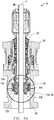
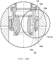
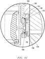
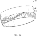
- the misalignment correction device 50 exemplary embodiment may also have one or more anti-rotational devices 190 to inhibit unintended rotation or spinning, such as the exemplary embodiment of an anti-rotational device 190 as depicted in Figure 8A and 8B and described above.
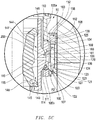
- the latch assembly 30 may include a seal 35 to sealingly engage the spherical shoulder 21.
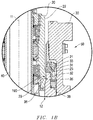
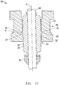
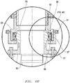
- the exemplary embodiment of the misalignment correction device 50 shown in Figures 3A-C may optionally further include one or more thrust bearings 90 (depicted in Figures 4A-C ).
- thrust bearings 90 depictted in Figures 4A-C .
- FIG. 4A-C there are two thrust bearings 90 in the exemplary embodiment of Figures 4A-C : one thrust bearing 90a installed between the upper plate 61a and the housing interior wall 66, and one thrust bearing 90b installed between the lower plate 61b and the housing interior wall 66; however, it should be appreciated that any number of thrust bearings 90 may be installed between the plates 61 and the housing 62. In alternate exemplary embodiments, the thrust bearings 90 may be installed elsewhere on or within the RCD 10.
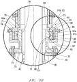
- Each of the thrust bearings 150 incorporates a fixed ring 151, a sliding or movable ring 153 and bearings 152 between the rings 151 and 153.
- the fixed ring 151 is attached or mounted to the carrier 100.
- the sliding or movable ring 153 is attached to the plates 105, and may slide radially or horizontally into and out of chamber 154 in response to plates 105 shifting towards or away from the axis 11.
- the bearings 152 sit in between the rings 151, 153 and may be any suitable type of rolling type bearings including but not limited to: balls, cylindrical rollers, spherical rollers, tapered rollers, and needle rollers.
- the thrust bearings 150 enable the plates 105 to more easily slide or shift in compensating for any horizontal misalignment and also help to minimize damage to the RCD 10, bearing assembly 20, latch assembly 30 and piece of oilfield equipment 40.
- the outer surface 176 of the plates 173 do not sit fully flush against the interior wall 171a.
- the inner surface 175 of the plates 173 are machined into a socket shape profile 200 to engage the spherical shoulder 181 of floating joint 180.
- the plates 173, further, may include seals 178 to sealingly engage the top and bottom surfaces of plates 173 that are adjacent to the spool 170 and the inner surface 115 adjacent to the spherical shoulder 181 of floating joint 180.
- the spherical shoulder 181 engages with and is supported by the inner surface 175 of the plates 173.
- the interior wall 171 of the spool 170 does not contact the floating joint 180 while there is no misalignment.
- the interior wall 171 is arranged such that there is an annular space 186 between the interior wall 171 of the spool 170 and the exterior surface 182 of the floating joint 180. This annular space 186 may be increased or decreased as desired for the needs of the particular oilfield operation, and may exist above and below the spherical shoulder 181.
Landscapes
- Engineering & Computer Science (AREA)
- Geology (AREA)
- Life Sciences & Earth Sciences (AREA)
- Mining & Mineral Resources (AREA)
- Physics & Mathematics (AREA)
- Environmental & Geological Engineering (AREA)
- Fluid Mechanics (AREA)
- General Life Sciences & Earth Sciences (AREA)
- Geochemistry & Mineralogy (AREA)
- Mechanical Engineering (AREA)
- Earth Drilling (AREA)
- Orthopedics, Nursing, And Contraception (AREA)
- Percussion Or Vibration Massage (AREA)
Claims (12)
- Drehende Kontrollvorrichtung (RCD) (10), die Folgendes umfasst:mindestens ein Abdichtungselement (80), das zum abdichtenden In-Eingriff-Nehmen eines Teils einer Ölfeld-Ausrüstung (40) konfiguriert ist,eine Lagerbaugruppe (20), die eine Drehung des Abdichtungselements (80) um eine Längsachse der RCD (10) ermöglicht,wobei die Lagerbaugruppe (20) einen äußeren bogenförmigen Absatz (21) aufweist undeine Klinkenbaugruppe (30), die mindestens eine Verriegelungsnase (33) einschließt, die ein inneres bogenförmiges Profil (34) aufweist, wobei die Verriegelungsnase (33) in Radialrichtung in Eingriff mit dem bogenförmigen Absatz (21) verschiebbar ist, um dadurch die Lagerbaugruppe (20) lösbar an der Klinkenbaugruppe (30) zu befestigen, und wobei, während das bogenförmige Profil (34) der Verriegelungsnase (33) mit dem bogenförmigen Absatz (21) in Eingriff gebracht ist, ermöglicht wird, dass sich die Lagerbaugruppe (20) um eine Achse, senkrecht zu der Längsachse (11), dreht.
- Drehende Kontrollvorrichtung nach Anspruch 1, die ferner eine Drehsicherungsvorrichtung (190) umfasst, die eine Drehung eines äußeren Elements der Lagerbaugruppe (20) um die Längsachse (11) verhindert.
- Drehende Kontrollvorrichtung nach einem der vorhergehenden Ansprüche, wobei die Klinkenbaugruppe (30) ferner eine Dichtung (35) einschließt, die den bogenförmigen Absatz (21) abdichtend in Eingriff nimmt.
- Drehende Kontrollvorrichtung nach einem der vorhergehenden Ansprüche, wobei ein ringförmiger Raum (12) zwischen der Lagerbaugruppe (20) und der Klinkenbaugruppe (30) eine Drehung der Lagerbaugruppe (20) um die Achse, senkrecht zu der Längsachse (11), begrenzt.
- Drehende Kontrollvorrichtung nach einem der vorhergehenden Ansprüche, wobei der bogenförmige Absatz (21) an einer Hülsenbaugruppe (24) geformt ist, die mit der Lagerbaugruppe (20) verbunden ist, wobei die Hülsenbaugruppe eine Hülse (27) einschließt.
- Drehende Kontrollvorrichtung nach Anspruch 5, wobei ein Drucklager (26) an einer Verbindung zwischen der Hülse (27) und dem bogenförmigen Absatz (21) angeordnet ist.
- Drehende Kontrollvorrichtung nach Anspruch 5 oder 6, wobei ein ringförmiger Hohlraum (25) zwischen dem bogenförmigen Absatz (21) und der Lagerbaugruppe (20) ermöglicht, dass sich die Lagerbaugruppe (20) in Radialrichtung im Verhältnis zu der Klinkenbaugruppe (30) verschiebt, wenn die Verriegelungsnase (33) mit dem bogenförmigen Absatz (21) in Eingriff gebracht ist.
- Verfahren zum Abschwächen einer Winkel-Fehlausrichtung zwischen einem Teil einer Ölfeld-Ausrüstung (40) und einer drehenden Kontrollvorrichtung (RCD) (10), wobei das Verfahren Folgendes umfasst:lösbares Befestigen einer Lagerbaugruppe (20) der RCD (10) an einer Klinkenbaugruppe (30), wobei das Befestigen das radiale Verschieben einer Verriegelungsnase (33) der Klinkenbaugruppe (30) in Eingriff mit einem Profil (23), das an der Lagerbaugruppe (20) geformt ist, umfasst, undabdichtendes In-Eingriff-Bringen des Teils einer Ölfeld-Ausrüstung (40) mit mindestens einem Abdichtungselement (80) der RCD (10),wobei:das Profil (23) einen äußeren bogenförmigen Absatz (21) umfasst und die Verriegelungsnase (33) ein inneres bogenförmiges Profil (34) aufweist, das den bogenförmigen Absatz (21) in Eingriff nimmt, wenn die Verriegelungsnase (33) in Radialrichtung in Eingriff mit dem Profil (23) verschoben wird, unddas Verfahren ferner das Drehen der Lagerbaugruppe (20) um eine Achse, senkrecht zu der Längsachse (11) der RCD (10), umfasst, wodurch eine Winkel-Fehlausrichtung zwischen dem Teil einer Ölfeld-Ausrüstung (40) und der RCD (10) abgeschwächt wird.
- Verfahren nach Anspruch 8, wobei ein ringförmiger Raum (12), der zwischen der RCD (10) und der Klinkenbaugruppe (30) geformt ist, eine Drehung der Lagerbaugruppe um die Achse, senkrecht zu der Längsachse (11), begrenzt.
- Verfahren nach Anspruch 9, wobei die Lagerbaugruppe (20) eine Drehung des Abdichtungselements (80) um die Längsachse (11) der RCD (10) ermöglicht.
- Verfahren nach Anspruch 10, das ferner das Verhindern einer Drehung eines äußeren Elements der RCD (10) um die Längsachse (11) mit einer Drehsicherungsvorrichtung (190) umfasst.
- Verfahren nach Anspruch 11, wobei die Drehsicherungsvorrichtung (190) mindestens einen Keil (36) an der Klinkenbaugruppe (30) umfasst, der mindestens einen Schlitz (29) an der Lagerbaugruppe (20) in Eingriff nimmt.
Applications Claiming Priority (3)
| Application Number | Priority Date | Filing Date | Title |
|---|---|---|---|
| US201462004624P | 2014-05-29 | 2014-05-29 | |
| EP15727285.7A EP3149268B1 (de) | 2014-05-29 | 2015-05-29 | Milderung der fehlausrichtung in einem rotierenden kontrolgerät |
| PCT/US2015/033209 WO2015184275A1 (en) | 2014-05-29 | 2015-05-29 | Misalignment mitigation in a rotating control device |
Related Parent Applications (2)
| Application Number | Title | Priority Date | Filing Date |
|---|---|---|---|
| EP15727285.7A Division-Into EP3149268B1 (de) | 2014-05-29 | 2015-05-29 | Milderung der fehlausrichtung in einem rotierenden kontrolgerät |
| EP15727285.7A Division EP3149268B1 (de) | 2014-05-29 | 2015-05-29 | Milderung der fehlausrichtung in einem rotierenden kontrolgerät |
Publications (2)
| Publication Number | Publication Date |
|---|---|
| EP3290633A1 EP3290633A1 (de) | 2018-03-07 |
| EP3290633B1 true EP3290633B1 (de) | 2020-07-29 |
Family
ID=53284686
Family Applications (3)
| Application Number | Title | Priority Date | Filing Date |
|---|---|---|---|
| EP17196403.4A Not-in-force EP3290633B1 (de) | 2014-05-29 | 2015-05-29 | Fehlausrichtungsverringerung in einer rotierenden steuerungsvorrichtung |
| EP15727285.7A Active EP3149268B1 (de) | 2014-05-29 | 2015-05-29 | Milderung der fehlausrichtung in einem rotierenden kontrolgerät |
| EP20210805.6A Active EP3805519B1 (de) | 2014-05-29 | 2015-05-29 | Fehlausrichtungsverringerung in einer rotierenden steuerungsvorrichtung |
Family Applications After (2)
| Application Number | Title | Priority Date | Filing Date |
|---|---|---|---|
| EP15727285.7A Active EP3149268B1 (de) | 2014-05-29 | 2015-05-29 | Milderung der fehlausrichtung in einem rotierenden kontrolgerät |
| EP20210805.6A Active EP3805519B1 (de) | 2014-05-29 | 2015-05-29 | Fehlausrichtungsverringerung in einer rotierenden steuerungsvorrichtung |
Country Status (9)
| Country | Link |
|---|---|
| US (1) | US9932786B2 (de) |
| EP (3) | EP3290633B1 (de) |
| AU (1) | AU2015266783C1 (de) |
| BR (1) | BR112016025078A2 (de) |
| CA (1) | CA2946005C (de) |
| EA (1) | EA201692141A1 (de) |
| MX (2) | MX2016014194A (de) |
| SG (1) | SG11201609034RA (de) |
| WO (1) | WO2015184275A1 (de) |
Families Citing this family (6)
| Publication number | Priority date | Publication date | Assignee | Title |
|---|---|---|---|---|
| WO2015184275A1 (en) * | 2014-05-29 | 2015-12-03 | Weatherford Technology Holdings, Llc | Misalignment mitigation in a rotating control device |
| US11473377B2 (en) | 2019-04-12 | 2022-10-18 | NTDrill Holdings, LLC | Rotating control device with flexible sleeve |
| EP4248056A4 (de) * | 2020-11-19 | 2024-10-23 | Opla Energy Ltd. | Drehsteuerungsvorrichtung |
| US12110757B2 (en) | 2020-11-21 | 2024-10-08 | Electrical Subsea & Drilling As | Packer arrangement for sealingly guiding a drillstring therethrough |
| NO347017B1 (no) * | 2020-11-21 | 2023-04-11 | Electrical Subsea & Drilling As | Pakningsarrangement for tettende gjennomføring av en borestreng |
| WO2025097233A1 (en) * | 2023-11-10 | 2025-05-15 | Beyond Energy Services And Technology Corp. | Rotating control device retaining mechanism |
Family Cites Families (15)
| Publication number | Priority date | Publication date | Assignee | Title |
|---|---|---|---|---|
| US5647444A (en) * | 1992-09-18 | 1997-07-15 | Williams; John R. | Rotating blowout preventor |
| US5662181A (en) | 1992-09-30 | 1997-09-02 | Williams; John R. | Rotating blowout preventer |
| US6138774A (en) | 1998-03-02 | 2000-10-31 | Weatherford Holding U.S., Inc. | Method and apparatus for drilling a borehole into a subsea abnormal pore pressure environment |
| US6263982B1 (en) | 1998-03-02 | 2001-07-24 | Weatherford Holding U.S., Inc. | Method and system for return of drilling fluid from a sealed marine riser to a floating drilling rig while drilling |
| GB2345074A (en) | 1998-12-24 | 2000-06-28 | Weatherford Lamb | Floating joint to facilitate the connection of tubulars using a top drive |
| US7159669B2 (en) | 1999-03-02 | 2007-01-09 | Weatherford/Lamb, Inc. | Internal riser rotating control head |
| US7926593B2 (en) | 2004-11-23 | 2011-04-19 | Weatherford/Lamb, Inc. | Rotating control device docking station |
| US8286734B2 (en) * | 2007-10-23 | 2012-10-16 | Weatherford/Lamb, Inc. | Low profile rotating control device |
| US8844652B2 (en) * | 2007-10-23 | 2014-09-30 | Weatherford/Lamb, Inc. | Interlocking low profile rotating control device |
| US8347983B2 (en) * | 2009-07-31 | 2013-01-08 | Weatherford/Lamb, Inc. | Drilling with a high pressure rotating control device |
| US9010433B2 (en) * | 2010-07-16 | 2015-04-21 | Weatherford Technology Holdings, Llc | Positive retraction latch locking dog for a rotating control device |
| GB2501489A (en) * | 2012-04-24 | 2013-10-30 | First Subsea Ltd | Rotatable joint for receiving a tubular |
| EP2864580A2 (de) * | 2012-06-25 | 2015-04-29 | Weatherford Technology Holdings, LLC | Führung für ein dichtungselement |
| GB2524790B (en) * | 2014-04-02 | 2018-02-07 | Schlumberger Holdings | Aligning borehole drilling equipment |
| WO2015184275A1 (en) * | 2014-05-29 | 2015-12-03 | Weatherford Technology Holdings, Llc | Misalignment mitigation in a rotating control device |
-
2015
- 2015-05-29 WO PCT/US2015/033209 patent/WO2015184275A1/en not_active Ceased
- 2015-05-29 EP EP17196403.4A patent/EP3290633B1/de not_active Not-in-force
- 2015-05-29 EA EA201692141A patent/EA201692141A1/ru unknown
- 2015-05-29 MX MX2016014194A patent/MX2016014194A/es unknown
- 2015-05-29 SG SG11201609034RA patent/SG11201609034RA/en unknown
- 2015-05-29 BR BR112016025078-8A patent/BR112016025078A2/pt active Search and Examination
- 2015-05-29 EP EP15727285.7A patent/EP3149268B1/de active Active
- 2015-05-29 CA CA2946005A patent/CA2946005C/en not_active Expired - Fee Related
- 2015-05-29 US US14/725,291 patent/US9932786B2/en active Active
- 2015-05-29 EP EP20210805.6A patent/EP3805519B1/de active Active
- 2015-05-29 AU AU2015266783A patent/AU2015266783C1/en not_active Ceased
-
2016
- 2016-10-28 MX MX2022006598A patent/MX2022006598A/es unknown
Non-Patent Citations (1)
| Title |
|---|
| None * |
Also Published As
| Publication number | Publication date |
|---|---|
| EP3149268B1 (de) | 2020-12-02 |
| AU2015266783A1 (en) | 2016-10-27 |
| EP3290633A1 (de) | 2018-03-07 |
| EP3149268A1 (de) | 2017-04-05 |
| MX2016014194A (es) | 2017-02-13 |
| EP3805519A1 (de) | 2021-04-14 |
| EP3805519B1 (de) | 2024-01-24 |
| AU2015266783C1 (en) | 2018-04-19 |
| EA201692141A1 (ru) | 2017-04-28 |
| MX2022006598A (es) | 2022-07-11 |
| CA2946005C (en) | 2018-12-04 |
| US20150345236A1 (en) | 2015-12-03 |
| US9932786B2 (en) | 2018-04-03 |
| SG11201609034RA (en) | 2016-11-29 |
| CA2946005A1 (en) | 2015-12-03 |
| WO2015184275A1 (en) | 2015-12-03 |
| BR112016025078A2 (pt) | 2018-05-15 |
| AU2015266783B2 (en) | 2017-04-20 |
Similar Documents
| Publication | Publication Date | Title |
|---|---|---|
| EP3290633B1 (de) | Fehlausrichtungsverringerung in einer rotierenden steuerungsvorrichtung | |
| EP2834448B1 (de) | Bohrlochverbinder mit gleitdichtungselement und verfahren zur verwendung davon | |
| US8499838B2 (en) | Subsea locking connector | |
| US20090294129A1 (en) | Subsea stack alignment method | |
| CA2942840C (en) | Sealing element mounting | |
| US20220127913A1 (en) | Rotatable mandrel hanger | |
| EP3230552B1 (de) | Ausrichtungssystem und -verfahren für eine hydraulische kupplung von hilfsleitungen | |
| US10677004B2 (en) | Riser with internal rotating flow control device | |
| CA2853642C (en) | Riser with internal rotating flow control device |
Legal Events
| Date | Code | Title | Description |
|---|---|---|---|
| PUAI | Public reference made under article 153(3) epc to a published international application that has entered the european phase |
Free format text: ORIGINAL CODE: 0009012 |
|
| STAA | Information on the status of an ep patent application or granted ep patent |
Free format text: STATUS: THE APPLICATION HAS BEEN PUBLISHED |
|
| AC | Divisional application: reference to earlier application |
Ref document number: 3149268 Country of ref document: EP Kind code of ref document: P |
|
| AK | Designated contracting states |
Kind code of ref document: A1 Designated state(s): AL AT BE BG CH CY CZ DE DK EE ES FI FR GB GR HR HU IE IS IT LI LT LU LV MC MK MT NL NO PL PT RO RS SE SI SK SM TR |
|
| STAA | Information on the status of an ep patent application or granted ep patent |
Free format text: STATUS: REQUEST FOR EXAMINATION WAS MADE |
|
| 17P | Request for examination filed |
Effective date: 20180903 |
|
| RBV | Designated contracting states (corrected) |
Designated state(s): AL AT BE BG CH CY CZ DE DK EE ES FI FR GB GR HR HU IE IS IT LI LT LU LV MC MK MT NL NO PL PT RO RS SE SI SK SM TR |
|
| STAA | Information on the status of an ep patent application or granted ep patent |
Free format text: STATUS: EXAMINATION IS IN PROGRESS |
|
| 17Q | First examination report despatched |
Effective date: 20190902 |
|
| GRAP | Despatch of communication of intention to grant a patent |
Free format text: ORIGINAL CODE: EPIDOSNIGR1 |
|
| STAA | Information on the status of an ep patent application or granted ep patent |
Free format text: STATUS: GRANT OF PATENT IS INTENDED |
|
| INTG | Intention to grant announced |
Effective date: 20200211 |
|
| GRAS | Grant fee paid |
Free format text: ORIGINAL CODE: EPIDOSNIGR3 |
|
| GRAA | (expected) grant |
Free format text: ORIGINAL CODE: 0009210 |
|
| STAA | Information on the status of an ep patent application or granted ep patent |
Free format text: STATUS: THE PATENT HAS BEEN GRANTED |
|
| AC | Divisional application: reference to earlier application |
Ref document number: 3149268 Country of ref document: EP Kind code of ref document: P |
|
| AK | Designated contracting states |
Kind code of ref document: B1 Designated state(s): AL AT BE BG CH CY CZ DE DK EE ES FI FR GB GR HR HU IE IS IT LI LT LU LV MC MK MT NL NO PL PT RO RS SE SI SK SM TR |
|
| REG | Reference to a national code |
Ref country code: CH Ref legal event code: EP |
|
| REG | Reference to a national code |
Ref country code: DE Ref legal event code: R096 Ref document number: 602015056747 Country of ref document: DE |
|
| REG | Reference to a national code |
Ref country code: AT Ref legal event code: REF Ref document number: 1296004 Country of ref document: AT Kind code of ref document: T Effective date: 20200815 |
|
| 111Z | Information provided on other rights and legal means of execution |
Free format text: AL AT BE BG CH CY CZ DE DK EE ES FI FR GB GR HR HU IE IS IT LT LU LV MC MK MT NL NO PL PT RO RS SE SI SK SM TR AL AT BE BG CH CY CZ DE DK EE ES FI FR GB GR HR HU IE IS IT LT LU LV MC MK MT NL NO PL PT RO RS SE SI SK SM TR Effective date: 20200511 |
|
| REG | Reference to a national code |
Ref country code: IE Ref legal event code: FG4D |
|
| REG | Reference to a national code |
Ref country code: LT Ref legal event code: MG4D |
|
| REG | Reference to a national code |
Ref country code: NO Ref legal event code: T2 Effective date: 20200729 |
|
| REG | Reference to a national code |
Ref country code: GB Ref legal event code: 732E Free format text: REGISTERED BETWEEN 20201126 AND 20201202 |
|
| REG | Reference to a national code |
Ref country code: NL Ref legal event code: MP Effective date: 20200729 |
|
| REG | Reference to a national code |
Ref country code: AT Ref legal event code: MK05 Ref document number: 1296004 Country of ref document: AT Kind code of ref document: T Effective date: 20200729 |
|
| PG25 | Lapsed in a contracting state [announced via postgrant information from national office to epo] |
Ref country code: HR Free format text: LAPSE BECAUSE OF FAILURE TO SUBMIT A TRANSLATION OF THE DESCRIPTION OR TO PAY THE FEE WITHIN THE PRESCRIBED TIME-LIMIT Effective date: 20200729 Ref country code: LT Free format text: LAPSE BECAUSE OF FAILURE TO SUBMIT A TRANSLATION OF THE DESCRIPTION OR TO PAY THE FEE WITHIN THE PRESCRIBED TIME-LIMIT Effective date: 20200729 Ref country code: AT Free format text: LAPSE BECAUSE OF FAILURE TO SUBMIT A TRANSLATION OF THE DESCRIPTION OR TO PAY THE FEE WITHIN THE PRESCRIBED TIME-LIMIT Effective date: 20200729 Ref country code: FI Free format text: LAPSE BECAUSE OF FAILURE TO SUBMIT A TRANSLATION OF THE DESCRIPTION OR TO PAY THE FEE WITHIN THE PRESCRIBED TIME-LIMIT Effective date: 20200729 Ref country code: SE Free format text: LAPSE BECAUSE OF FAILURE TO SUBMIT A TRANSLATION OF THE DESCRIPTION OR TO PAY THE FEE WITHIN THE PRESCRIBED TIME-LIMIT Effective date: 20200729 Ref country code: PT Free format text: LAPSE BECAUSE OF FAILURE TO SUBMIT A TRANSLATION OF THE DESCRIPTION OR TO PAY THE FEE WITHIN THE PRESCRIBED TIME-LIMIT Effective date: 20201130 Ref country code: GR Free format text: LAPSE BECAUSE OF FAILURE TO SUBMIT A TRANSLATION OF THE DESCRIPTION OR TO PAY THE FEE WITHIN THE PRESCRIBED TIME-LIMIT Effective date: 20201030 Ref country code: ES Free format text: LAPSE BECAUSE OF FAILURE TO SUBMIT A TRANSLATION OF THE DESCRIPTION OR TO PAY THE FEE WITHIN THE PRESCRIBED TIME-LIMIT Effective date: 20200729 Ref country code: BG Free format text: LAPSE BECAUSE OF FAILURE TO SUBMIT A TRANSLATION OF THE DESCRIPTION OR TO PAY THE FEE WITHIN THE PRESCRIBED TIME-LIMIT Effective date: 20201029 |
|
| PG25 | Lapsed in a contracting state [announced via postgrant information from national office to epo] |
Ref country code: LV Free format text: LAPSE BECAUSE OF FAILURE TO SUBMIT A TRANSLATION OF THE DESCRIPTION OR TO PAY THE FEE WITHIN THE PRESCRIBED TIME-LIMIT Effective date: 20200729 Ref country code: PL Free format text: LAPSE BECAUSE OF FAILURE TO SUBMIT A TRANSLATION OF THE DESCRIPTION OR TO PAY THE FEE WITHIN THE PRESCRIBED TIME-LIMIT Effective date: 20200729 Ref country code: RS Free format text: LAPSE BECAUSE OF FAILURE TO SUBMIT A TRANSLATION OF THE DESCRIPTION OR TO PAY THE FEE WITHIN THE PRESCRIBED TIME-LIMIT Effective date: 20200729 Ref country code: IS Free format text: LAPSE BECAUSE OF FAILURE TO SUBMIT A TRANSLATION OF THE DESCRIPTION OR TO PAY THE FEE WITHIN THE PRESCRIBED TIME-LIMIT Effective date: 20201129 |
|
| REG | Reference to a national code |
Ref country code: GB Ref legal event code: 732E Free format text: REGISTERED BETWEEN 20210225 AND 20210303 |
|
| PG25 | Lapsed in a contracting state [announced via postgrant information from national office to epo] |
Ref country code: NL Free format text: LAPSE BECAUSE OF FAILURE TO SUBMIT A TRANSLATION OF THE DESCRIPTION OR TO PAY THE FEE WITHIN THE PRESCRIBED TIME-LIMIT Effective date: 20200729 |
|
| PG25 | Lapsed in a contracting state [announced via postgrant information from national office to epo] |
Ref country code: SM Free format text: LAPSE BECAUSE OF FAILURE TO SUBMIT A TRANSLATION OF THE DESCRIPTION OR TO PAY THE FEE WITHIN THE PRESCRIBED TIME-LIMIT Effective date: 20200729 Ref country code: IT Free format text: LAPSE BECAUSE OF FAILURE TO SUBMIT A TRANSLATION OF THE DESCRIPTION OR TO PAY THE FEE WITHIN THE PRESCRIBED TIME-LIMIT Effective date: 20200729 Ref country code: EE Free format text: LAPSE BECAUSE OF FAILURE TO SUBMIT A TRANSLATION OF THE DESCRIPTION OR TO PAY THE FEE WITHIN THE PRESCRIBED TIME-LIMIT Effective date: 20200729 Ref country code: RO Free format text: LAPSE BECAUSE OF FAILURE TO SUBMIT A TRANSLATION OF THE DESCRIPTION OR TO PAY THE FEE WITHIN THE PRESCRIBED TIME-LIMIT Effective date: 20200729 Ref country code: CZ Free format text: LAPSE BECAUSE OF FAILURE TO SUBMIT A TRANSLATION OF THE DESCRIPTION OR TO PAY THE FEE WITHIN THE PRESCRIBED TIME-LIMIT Effective date: 20200729 Ref country code: DK Free format text: LAPSE BECAUSE OF FAILURE TO SUBMIT A TRANSLATION OF THE DESCRIPTION OR TO PAY THE FEE WITHIN THE PRESCRIBED TIME-LIMIT Effective date: 20200729 |
|
| REG | Reference to a national code |
Ref country code: DE Ref legal event code: R097 Ref document number: 602015056747 Country of ref document: DE |
|
| PG25 | Lapsed in a contracting state [announced via postgrant information from national office to epo] |
Ref country code: AL Free format text: LAPSE BECAUSE OF FAILURE TO SUBMIT A TRANSLATION OF THE DESCRIPTION OR TO PAY THE FEE WITHIN THE PRESCRIBED TIME-LIMIT Effective date: 20200729 |
|
| PLBE | No opposition filed within time limit |
Free format text: ORIGINAL CODE: 0009261 |
|
| STAA | Information on the status of an ep patent application or granted ep patent |
Free format text: STATUS: NO OPPOSITION FILED WITHIN TIME LIMIT |
|
| PG25 | Lapsed in a contracting state [announced via postgrant information from national office to epo] |
Ref country code: SK Free format text: LAPSE BECAUSE OF FAILURE TO SUBMIT A TRANSLATION OF THE DESCRIPTION OR TO PAY THE FEE WITHIN THE PRESCRIBED TIME-LIMIT Effective date: 20200729 |
|
| 26N | No opposition filed |
Effective date: 20210430 |
|
| PG25 | Lapsed in a contracting state [announced via postgrant information from national office to epo] |
Ref country code: SI Free format text: LAPSE BECAUSE OF FAILURE TO SUBMIT A TRANSLATION OF THE DESCRIPTION OR TO PAY THE FEE WITHIN THE PRESCRIBED TIME-LIMIT Effective date: 20200729 |
|
| REG | Reference to a national code |
Ref country code: GB Ref legal event code: 732E Free format text: REGISTERED BETWEEN 20210812 AND 20210818 |
|
| REG | Reference to a national code |
Ref country code: DE Ref legal event code: R119 Ref document number: 602015056747 Country of ref document: DE |
|
| REG | Reference to a national code |
Ref country code: NO Ref legal event code: MMEP |
|
| REG | Reference to a national code |
Ref country code: CH Ref legal event code: PL |
|
| GBPC | Gb: european patent ceased through non-payment of renewal fee |
Effective date: 20210529 |
|
| PG25 | Lapsed in a contracting state [announced via postgrant information from national office to epo] |
Ref country code: CH Free format text: LAPSE BECAUSE OF NON-PAYMENT OF DUE FEES Effective date: 20210531 Ref country code: MC Free format text: LAPSE BECAUSE OF FAILURE TO SUBMIT A TRANSLATION OF THE DESCRIPTION OR TO PAY THE FEE WITHIN THE PRESCRIBED TIME-LIMIT Effective date: 20200729 Ref country code: LI Free format text: LAPSE BECAUSE OF NON-PAYMENT OF DUE FEES Effective date: 20210531 Ref country code: LU Free format text: LAPSE BECAUSE OF NON-PAYMENT OF DUE FEES Effective date: 20210529 Ref country code: NO Free format text: LAPSE BECAUSE OF NON-PAYMENT OF DUE FEES Effective date: 20210531 |
|
| REG | Reference to a national code |
Ref country code: BE Ref legal event code: MM Effective date: 20210531 |
|
| PG25 | Lapsed in a contracting state [announced via postgrant information from national office to epo] |
Ref country code: IE Free format text: LAPSE BECAUSE OF NON-PAYMENT OF DUE FEES Effective date: 20210529 Ref country code: GB Free format text: LAPSE BECAUSE OF NON-PAYMENT OF DUE FEES Effective date: 20210529 Ref country code: DE Free format text: LAPSE BECAUSE OF NON-PAYMENT OF DUE FEES Effective date: 20211201 |
|
| PG25 | Lapsed in a contracting state [announced via postgrant information from national office to epo] |
Ref country code: FR Free format text: LAPSE BECAUSE OF NON-PAYMENT OF DUE FEES Effective date: 20210531 |
|
| PG25 | Lapsed in a contracting state [announced via postgrant information from national office to epo] |
Ref country code: BE Free format text: LAPSE BECAUSE OF NON-PAYMENT OF DUE FEES Effective date: 20210531 |
|
| PG25 | Lapsed in a contracting state [announced via postgrant information from national office to epo] |
Ref country code: HU Free format text: LAPSE BECAUSE OF FAILURE TO SUBMIT A TRANSLATION OF THE DESCRIPTION OR TO PAY THE FEE WITHIN THE PRESCRIBED TIME-LIMIT; INVALID AB INITIO Effective date: 20150529 |
|
| PG25 | Lapsed in a contracting state [announced via postgrant information from national office to epo] |
Ref country code: CY Free format text: LAPSE BECAUSE OF FAILURE TO SUBMIT A TRANSLATION OF THE DESCRIPTION OR TO PAY THE FEE WITHIN THE PRESCRIBED TIME-LIMIT Effective date: 20200729 |
|
| P01 | Opt-out of the competence of the unified patent court (upc) registered |
Effective date: 20230922 |
|
| PG25 | Lapsed in a contracting state [announced via postgrant information from national office to epo] |
Ref country code: MK Free format text: LAPSE BECAUSE OF FAILURE TO SUBMIT A TRANSLATION OF THE DESCRIPTION OR TO PAY THE FEE WITHIN THE PRESCRIBED TIME-LIMIT Effective date: 20200729 |
|
| PG25 | Lapsed in a contracting state [announced via postgrant information from national office to epo] |
Ref country code: MT Free format text: LAPSE BECAUSE OF FAILURE TO SUBMIT A TRANSLATION OF THE DESCRIPTION OR TO PAY THE FEE WITHIN THE PRESCRIBED TIME-LIMIT Effective date: 20200729 |
|
| PG25 | Lapsed in a contracting state [announced via postgrant information from national office to epo] |
Ref country code: TR Free format text: LAPSE BECAUSE OF FAILURE TO SUBMIT A TRANSLATION OF THE DESCRIPTION OR TO PAY THE FEE WITHIN THE PRESCRIBED TIME-LIMIT Effective date: 20200729 |